
图1 燃料电池-锂电池-超级电容混合供电系统架构
Fig.1 FC-BAT-SC HPSS Architecture
摘要 混合供电系统可充分利用不同供电源的特性,大幅提升电气化交通系统供电性能。然而,大负载投切极端情况极易引起供电系统失稳,采用小信号稳定分析法难以完整覆盖此类大扰动工况。为此,该文基于最大吸引域估计研究计及控制动态的混合供电系统大信号稳定性分析问题,深入剖析控制参数、负载功率变化等对系统大信号稳定性的影响,提出基于有源电容变换器吸收脉冲功率的混合供电系统大信号稳定性提升方案。研究表明,电阻下垂系数、电压电流环PI调节器比例增益和负载功率变化是混合供电系统的主导失稳特征,可通过优化控制参数增大系统的吸引域进而获得更大的稳定裕度。通过实验验证了所提大信号分析方法和稳定性提升策略的有效性。
关键词:大信号稳定性 吸引域 混合供电系统 脉冲负载 虚拟阻抗下垂控制
在交通电气化领域,基于氢燃料电池(Fuel Cell, FC)的供电系统以零碳排放、高能量密度等优良特性展现出广阔的应用前景[1-5]。然而,因FC存在动态响应慢、无法吸收回馈能量等问题,通常将其与具有快速动态响应特性的锂电池(Battery, BAT)和超级电容(Supercapacitor, SC)结合,构成混合供电系统(Hybrid Power Supply System, HPSS)[6]。此外,在负载侧,大量的新型电气化负荷不仅表现为恒功率负载(Constan Power Load, CPL)特性,还表现出强脉动以及低频强脉冲特性,复杂的源-荷交互会严重影响HPSS的稳定性。因此,对混合供电系统进行稳定性分析已成为保障其可靠运行的关键前提。
针对电力电子变换器主导的供电系统,现有的稳定性分析方法可分为小信号分析法和大信号分析法两种。小信号分析法相对成熟,其实施过程包含以下两个阶段:①在系统平衡点附近进行线性化以构建小信号模型;②运用特征值判据[7-8]、阻抗判据[9-11]、奈奎斯特稳定判据[12]等线性系统理论,实现对系统的稳定性评估。然而,当系统突然从空载切换至过载,或脉冲功率负载突然加载等大功率负载投切工况下,系统实际运行范围远超小信号所限定的平衡点附近。因此,仅根据小信号稳定性分析法对系统参数进行设计,难以有效地评估大信号扰动下系统的稳定性。
为了克服小信号分析的局限性,国内外学者提出了一系列基于吸引域(Region of Attraction, ROA)估计的大信号稳定性分析方法。ROA用于描述系统在某个平衡点(或稳定状态)周围的区域,是系统从任意初始状态出发后能渐近稳定于目标平衡点的所有初始状态的集合,可用来表征系统受到大扰动后的稳定边界。目前,常用的基于吸引域的大信号边界评估方法包括混合势函数理论(Mixed Potential Theory, MPT)[13]、平方和规划(Sum of Squares Programming, SOSP)[14]以及Takagi-Sugeno(T-S)模糊模型[15]等。文献[16]将多源直流微电网简化为含恒功率负载的源变换器系统,并基于MPT推导出系统的稳定参数范围。然而,因建模忽略了输出阻抗、线路阻抗以及控制系统动态影响,所得分析结果精度不高。文献[17]针对下垂阻抗控制下的直流微电网,考虑了输出阻抗和下垂阻抗的影响,并通过MPT获得保守性较低的吸引域。然而,该研究中同样忽略了控制系统动态,仅考虑了主电路参数的影响,导致其分析结果精度不足。此外,在考虑控制动态后,所构建的混合势函数将不再满足混合势函数理论的基本条件[18-19]。平方和规划方法直接由数学模型出发,将吸引域估计问题转化为SOSP,再转化为半正定规划求解系统Lyapunov函数[20],因此可在建模时考虑控制动态,提升分析结果的精度。文献[18]基于平方和规划法获得了级联电力电子系统的低保守性吸引域,但分析时仅考虑了电压外环控制而忽略电流内环响应动态。因电流环在负载切换工况中起关键作用,所得结果仍有待完善。文献[21-22]采用SOSP计算出了直流电源系统的吸引域,但分析的模型基础沿用了文献[16]所示降阶模型,不能充分揭示暂态失稳机理。此外,尽管平方和规划法在某些系统中可求解得出接近真实吸引域的估计吸引域[23],但高阶系统的平方和规划模型求解仍非常困难[24]。除上述方法外,基于T-S模糊模型的大信号分析方法也在分析过程中考虑控制动态影响。T-S模糊模型通过将吸引域估计问题转化为更易求解的线性矩阵不等式(Linear Matrix Inequality, LMI)问题,广泛应用于直流电源系统的稳定性分析中[25-28]。尽管如此,对于包含多类供电源与负载,通过电力电子变换器互联的高阶非线性混合供电系统,利用T-S模糊模型进行稳定性分析时仍存在因模型复杂、非线性变量多、分析工况多而导致分析难以进行的困难,急需展开研究。
针对上述问题,本文基于T-S模糊模型与李雅普诺夫稳定理论对燃料电池-锂电池-超级电容混合供电系统展开大信号稳定性分析研究,主要工作及创新点如下:
(1)建立了计及控制动态(含下垂控制、双闭环PI控制)的HPSS状态空间模型,解释了控制参数对大信号稳定性的影响机理。
(2)分析了系统在恒功率负载切换、脉冲负载加载工况下的大信号稳定性。此外,基于吸引域估计结果,阐明了脉冲功率解耦的重要性,并提出基于有源电容变换器(Active Capacitor Converter, ACC)的脉冲功率解耦方案,有效地提升了大信号稳定性。
本文所研究的FC-BAT-SC HPSS的拓扑结构如图1所示。该系统由FC及其端口单向Boost变换器、BAT和SC及其端口双向Buck-Boost变换器及各种负载组成。
图1 燃料电池-锂电池-超级电容混合供电系统架构
Fig.1 FC-BAT-SC HPSS Architecture
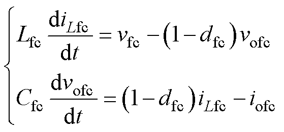
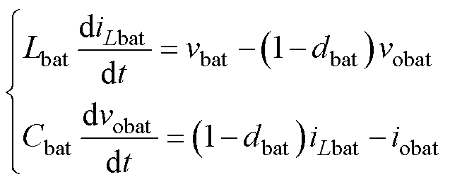
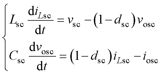
根据图1,HPSS主电路数学模型可表示为
 (1)
(1)
 (2)
(2)
 (3)
(3)
式中,Lfc、Lbat、Lsc、Cfc、Cbat、Csc、dfc、dbat、dsc、iLfc、iLbat、iLsc、iofc、iobat、iosc、vofc、vobat、vosc分别为FC、BAT、SC变换器的滤波电感、滤波电容、占空比、电感电流、输出电流和输出电压。
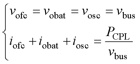
当忽略线路阻抗后,可得
 (4)
(4)
式中,vbus为母线电压;PCPL为CPL功率。
根据文献[29]可知,由于恒功率负载呈负阻尼特性,对电源系统的稳定性影响最大。因此,若负载全为恒功率系统能够保持稳定,则其余负载工况下系统均能保持稳定。
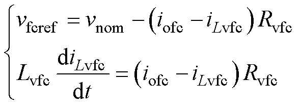
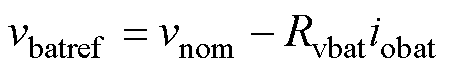
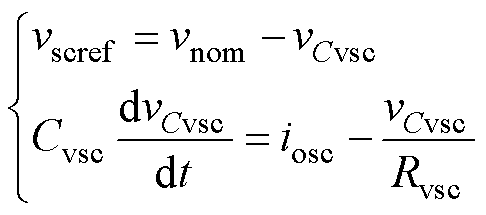
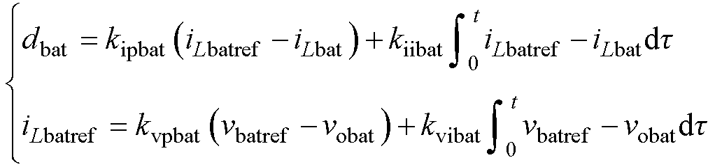
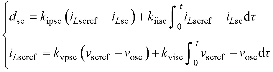
考虑到FC、BAT及SC的动态响应特性存在显著差异,本文采用虚拟阻抗下垂控制与双环PI控制相结合的控制策略实现负载功率在不同源间的动态分配以及电压电流调节[6],控制框图如图1所示。根据图1,采用虚拟阻抗下垂控制后,系统满足
 (5)
(5)
 (6)
(6)
 (7)
(7)
式中,vfcref、vbatref、vscref和vnom分别为FC、BAT和SC变换器虚拟阻抗下垂后的电压基准值和母线电压标称值;iLvfc为FC变换器虚拟电感电流;vCvsc为SC变换器虚拟电容电压;Rvfc、Rvbat、Rvsc、Lvfc和Cvsc分别为FC变换器阻性下垂系数、BAT变换器阻性下垂系数、SC变换器阻性下垂系数、FC变换器感性下垂系数和SC变换器容性下垂系数。
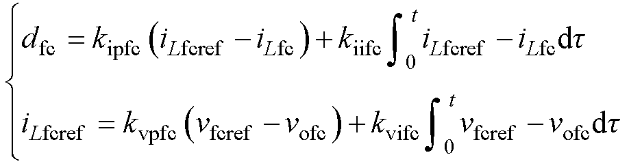
根据图1,各电源采用双闭环控制后的数学模型可表示为
 (8)
(8)
 (9)
(9)
 (10)
(10)
式中,kvpfc、kvifc、kipfc、kiifc、kvpbat、kvibat、kipbat、kiibat、kvpsc、kvisc、kipsc、kiisc分别为FC、BAT、SC变换器电压、电流环PI调节器的比例增益和积分增益。
对于典型的脉动负载,由FC、BAT和SC组成的HPSS能够有效地维持母线电压稳定。然而,当高峰均比脉冲功率加载时,上述HPSS母线电压将出现明显跌落甚至失稳的现象。为解决该问题,本文基于有源电容变换器[30]对脉冲负载进行了功率解耦。图1展示了有源电容变换器的控制原理框图,其电流环通过引入附加电流参考信号,使有源电容能快速地提供脉冲功率,实现功率解耦。由图1可知,有源电容变换器的电压控制环并非用于调节母线电压,而是实现储能电容电压的恢复。因此,当脉冲负载加载时,有源电容可等效为电流源以提供瞬时脉冲电流,在此期间有源电容与由FC、BAT和SC组成的电源系统不存在能量交互;而在非脉冲工况下,有源电容可视为常规负载。因此在进行稳定性分析时,有源电容变换器部分可视为常规负载。
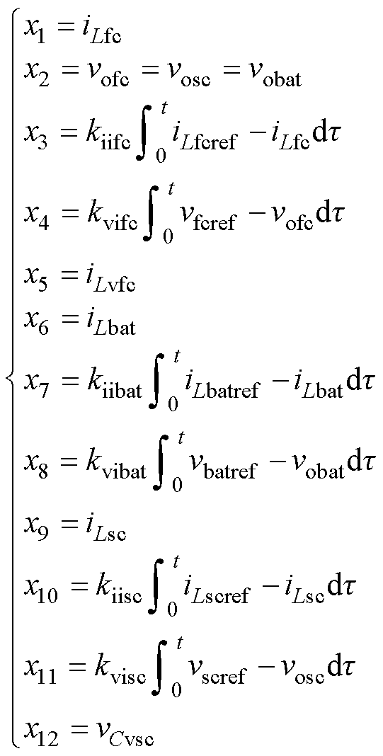
系统正常运行时,选取状态变量如下
 (11)
(11)
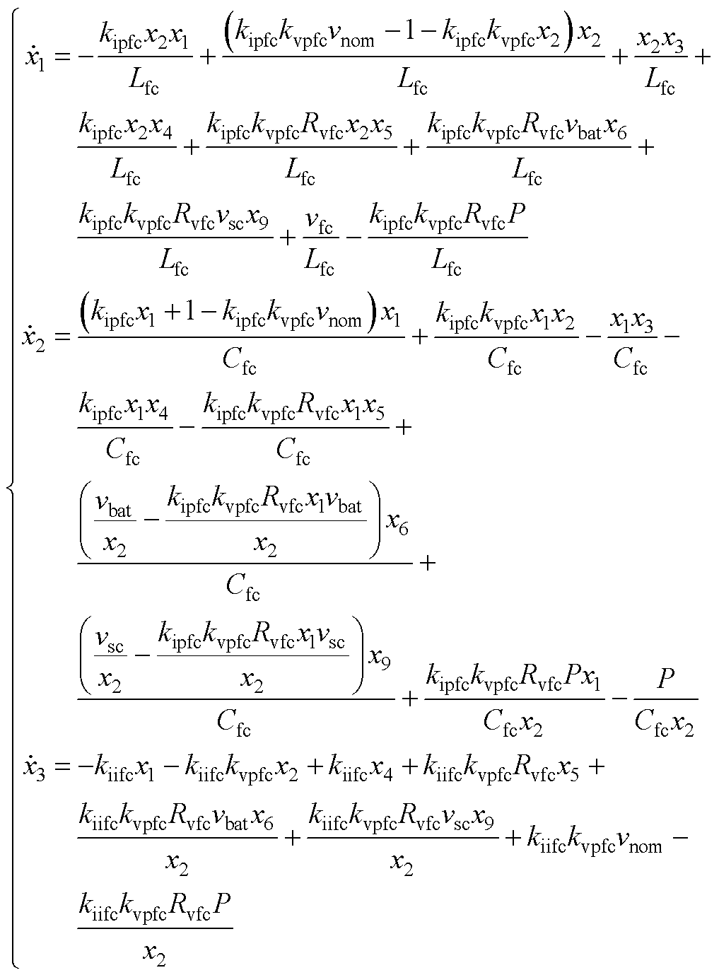
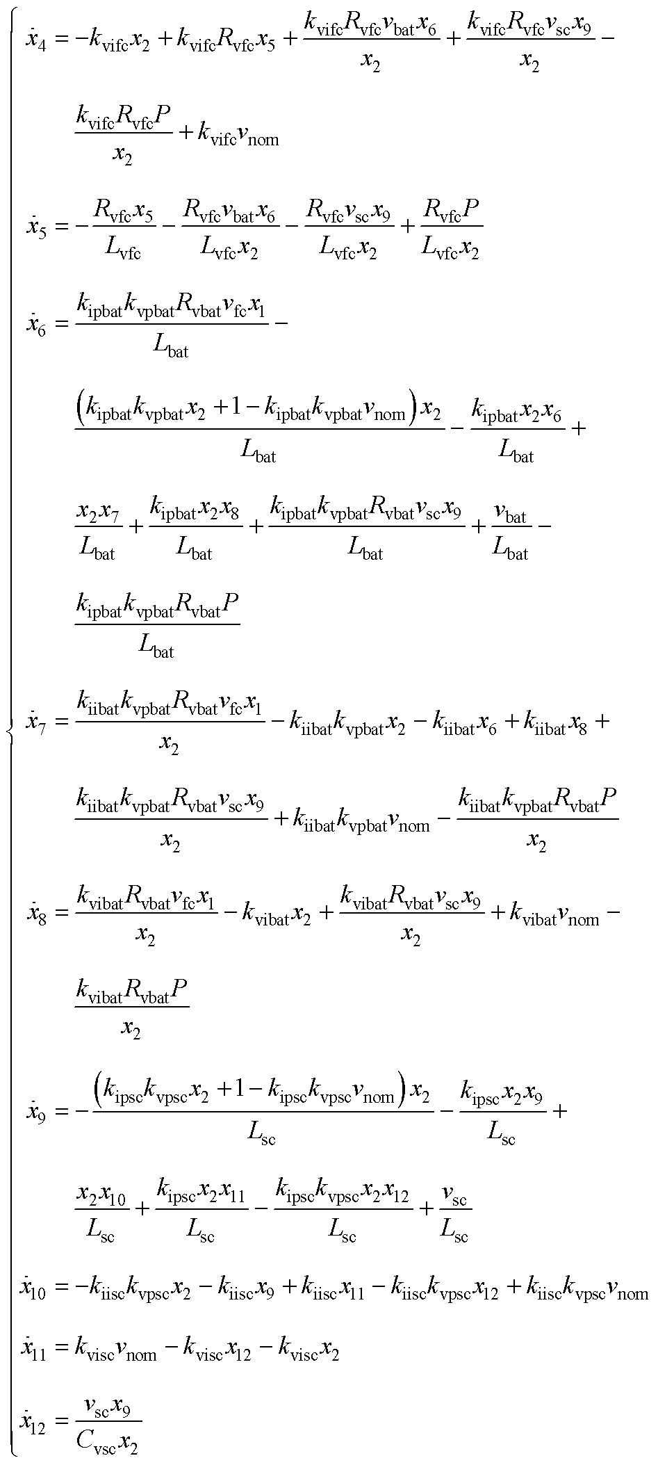
结合式(1)~式(11),可推导出整个系统正常运行时的状态空间模型为
 (12)
(12)
式中,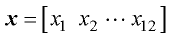 ;f1(x)的完整表达式详见附录式(A1)。
为了进一步分析系统的稳定性,通常需要将式(12)平衡点平移至原点,可表示为
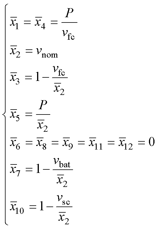 (13)
(13)
令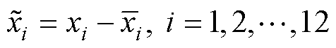 ,则式(13)可重新写为
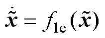 (14)
(14)
 的完整表达式详见附录式(A2)。
考虑非线性系统
 (15)
(15)
式中, 为局部Lipschitz连续函数;
 为包含原点的定义域。x=0为式(15)的渐近稳定平衡点;
 为式(15)在t=0时从初始状态x出发的解轨迹。此时,吸引域
 可定义为
可定义为
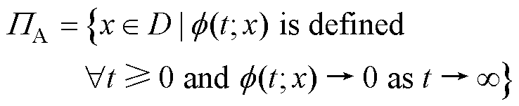 (16)
(16)
引理1:若x=0为式(15)的渐近稳定平衡点,则其吸引域是一个开放、连通的不变集,吸引域的边界由系统轨迹构成。
引理2:若存在一个连续可微函数 使得V(x)是正定的,
 有界,
有界,
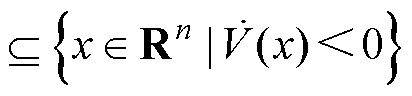 ,则
,则 是的一个子集(是的一个估计)。
图2为二维吸引域的示意图,其中估计吸引域严格包含于末状态实际吸引域的内部,该特性与引理2的结论一致。图2中初始状态1和初始状态2经过暂态过程后将收敛至末状态,而初始状态3因位于该吸引域外而无法实现收敛。对于HPSS,末状态通常是负载加载后的期望稳态平衡点。因此,准确获取末状态的吸引域边界可有效判定暂态过程的稳定性(也即大信号稳定性)。
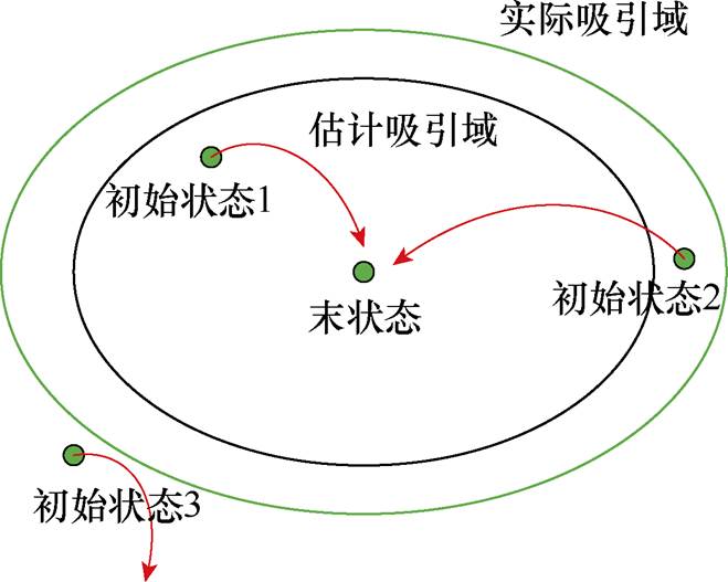
图2 二维吸引域示意图
Fig.2 Schematic diagram of a 2-dimensional ROA
根据第1节所述,本文核心在于估计系统式(14)在任意稳态下的吸引域。因此,基于文献[13]提出的T-S模糊建模方法,本文首先将原非线性系统转化为具有线性子系统结构的模糊模型进行逼近。因系统建模考虑了完备的控制系统动态,所得结果具有较好的精度。通过该转换,吸引域估计问题可转换为LMI框架下的Lyapunov函数求解问题。其中,详细的T-S模糊建模过程可参考文献[27-28],本文不再赘述。
根据式(14)可知,非线性主要由 和
和 引入,因此选取非线性项为
 (17)
(17)
式中, 为由和表示的基本函数,即式(14)中的非线性项。因此,设计模糊规则如下:
规则y1:如果 ,
, ,则非线性系统的局部线性模型为
 。
。
规则y2:如果, ,则非线性系统的局部线性模型为
 。
。
规则y3:如果 ,,则非线性系统的局部线性模型为
 。
。
规则y4:如果,,则非线性系统的局部线性模型为 。
。
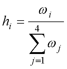
最终,式(14)的T-S模糊模型可表示为
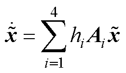 (18)
(18)
其中
根据Lyapunov稳定性理论,假设存在一个对称正定矩阵P,则系统式(14)的候选Lyapunov函数可表示为
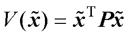 (19)
(19)
如果式(20)可行,则系统式(14)渐近稳定。
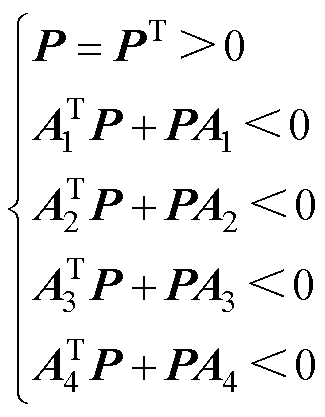 (20)
(20)
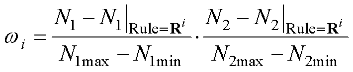
当 (i=1, 2)和
 从0开始分别逐渐增大和减小时,式(20)最终将无可行解,从而得到最大估计吸引域。其详细迭代过程可参考文献[25]。最终得到的估计吸引域可表示为
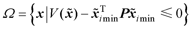 (21)
(21)
本节将基于表1所示HPSS参数,计算HPSS在不同控制参数和功率等级下的最大估计吸引域。图3展示了HPSS带6 kW恒功率负载时,下垂系数变化对HPSS最大估计吸引域的影响。从图3a可以看出,FC变换器电阻下垂系数对吸引域的变化有显著影响,表现为随着阻性下垂系数的增加,最大估计吸引域的大小显著减小。此外,从图3c和图3d可以看出,BAT和SC变换器电阻下垂系数的变化对最大估计吸引域无明显影响。从图3b和图3e可以看出,FC和SC变换器电感下垂系数和电容下垂系数的变化对最大估计吸引域无明显影响。
表1 系统参数
Tab.1 System parameters
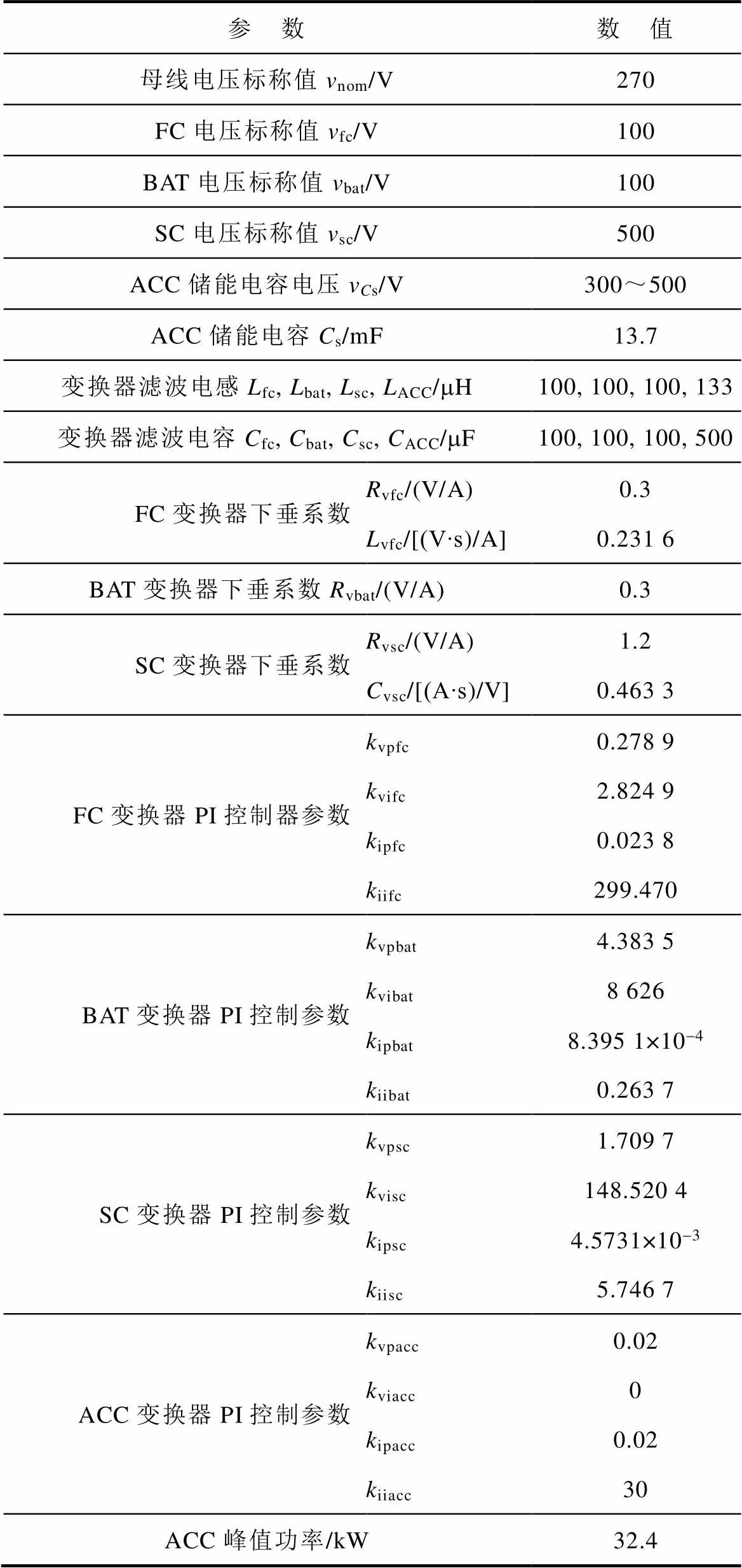
参 数数 值 母线电压标称值vnom/V270 FC电压标称值vfc/V100 BAT电压标称值vbat/V100 SC电压标称值vsc/V500 ACC储能电容电压vCs/V300~500 ACC储能电容Cs/mF13.7 变换器滤波电感Lfc, Lbat, Lsc, LACC/mH100, 100, 100, 133 变换器滤波电容Cfc, Cbat, Csc, CACC/mF100, 100, 100, 500 FC变换器下垂系数Rvfc/(V/A)0.3 Lvfc/[(V∙s)/A]0.231 6 BAT变换器下垂系数Rvbat/(V/A)0.3 SC变换器下垂系数Rvsc/(V/A)1.2 Cvsc/[(A∙s)/V]0.463 3 FC变换器PI控制器参数kvpfc0.278 9 kvifc2.824 9 kipfc0.023 8 kiifc299.470 BAT变换器PI控制参数kvpbat4.383 5 kvibat8 626 kipbat8.395 1×10⁻⁴ kiibat0.263 7 SC变换器PI控制参数kvpsc1.709 7 kvisc148.520 4 kipsc4.5731×10-3 kiisc5.746 7 ACC变换器PI控制参数kvpacc0.02 kviacc0 kipacc0.02 kiiacc30 ACC峰值功率/kW32.4
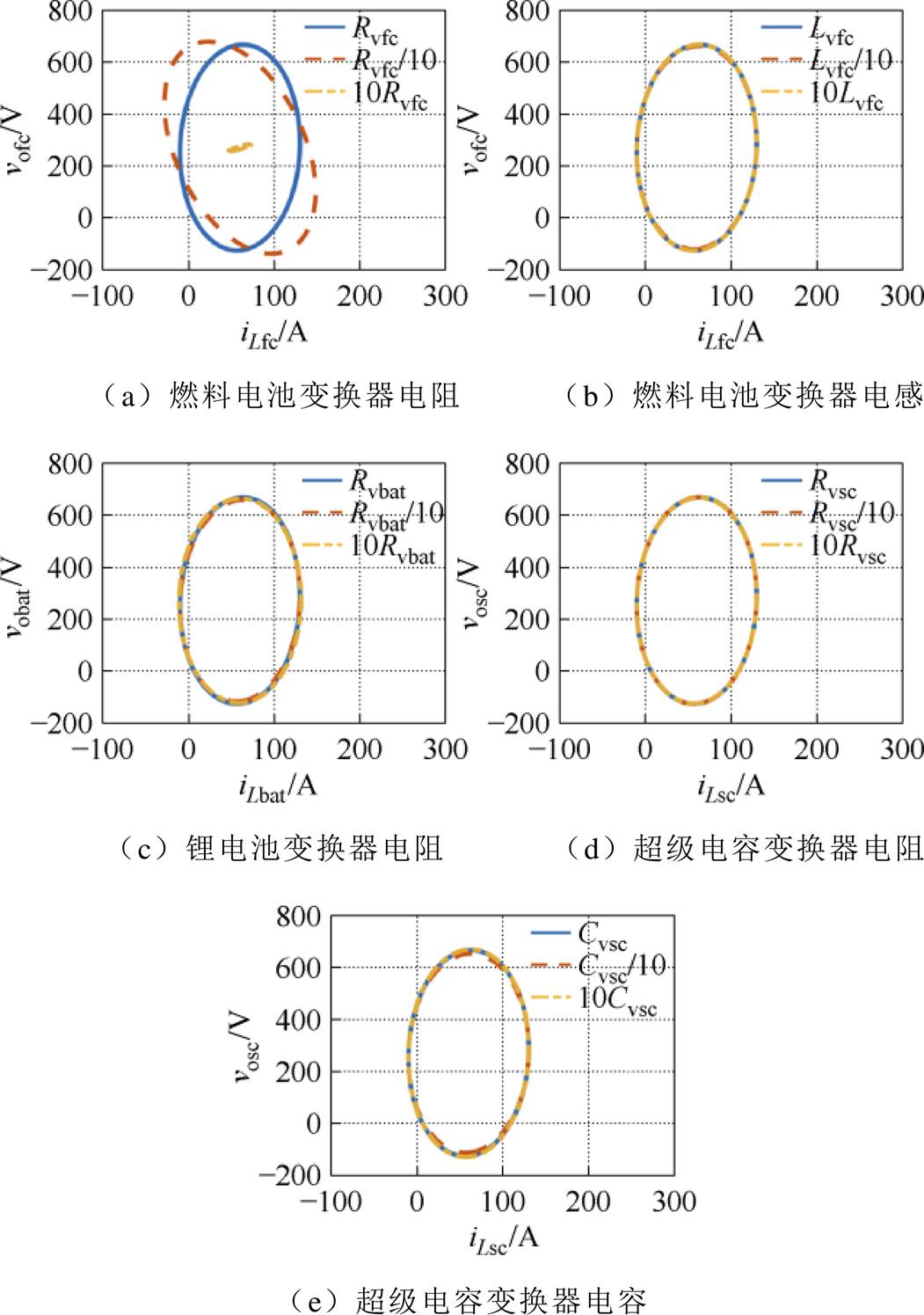
图3 下垂系数变化对最大估计吸引域的影响
Fig.3 The impact of droop coefficient variations on the largest estimated region of attraction
图4描述了HPSS带6 kW恒功率负载时,FC增益的变化对估计吸引域的影响,从图4a和图4c可以看出,比例增益对最大估计吸引域的大小有显著影响,表现为随着电压环比例增益的增大,最大估计吸引域的大小显著减小。从图4b和图4d可以看出,积分增益(电压环和电流环)的变化对最大估计吸引域无明显影响。

图4 燃料电池变换器PI调节器参数变化对最大估计吸引域的影响
Fig.4 The impact of PI regulator parameter variations in FC converters on the largest estimated region of attraction
图5给出了HPSS带6 kW恒功率负载时,BAT变换器PI调节器电压环和电流环比例增益和积分增益的变化对最大估计吸引域的影响。从图5a可以看出,随着电压环比例增益的增加,最大估计吸引域有轻微减小的趋势;从图5c可以看出,随着电流环比例增益的增大,最大估计吸引域呈现先增加后减小再旋转的趋势。从图5b和图5d可以看出,积分增益(电压环和电流环)的变化对最大估计吸引域无明显影响。
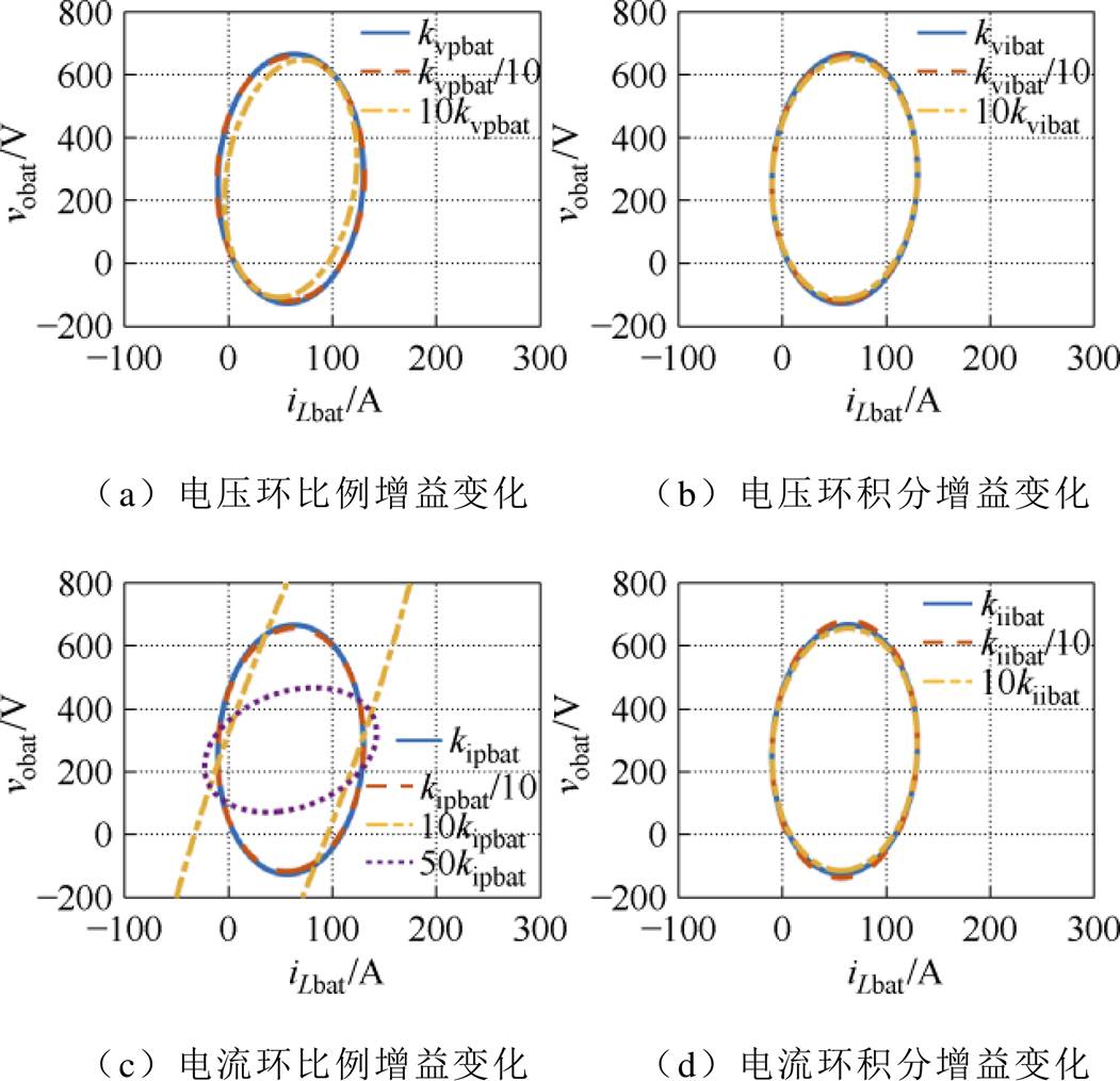
图5 锂电池变换器PI调节器参数变化对最大估计吸引域的影响
Fig.5 The impact of PI regulator parameter variations in BAT converters on the largest estimated region of attraction
图6所示为HPSS带6 kW恒功率负载时,SC变换器PI调节器电压环和电流环比例增益和积分增益的变化对估计吸引域的影响。从图6a、图6b和图6d可以看出,随着电压环比例增益、电压环积分增益和电流环积分增益的增加,最大估计吸引域呈显著减小的趋势。从图6c可以看出,随着电流环比例增益的增大,估计吸引域增加并向右旋转,增加至一定数值后,吸引域将不再明显变化。
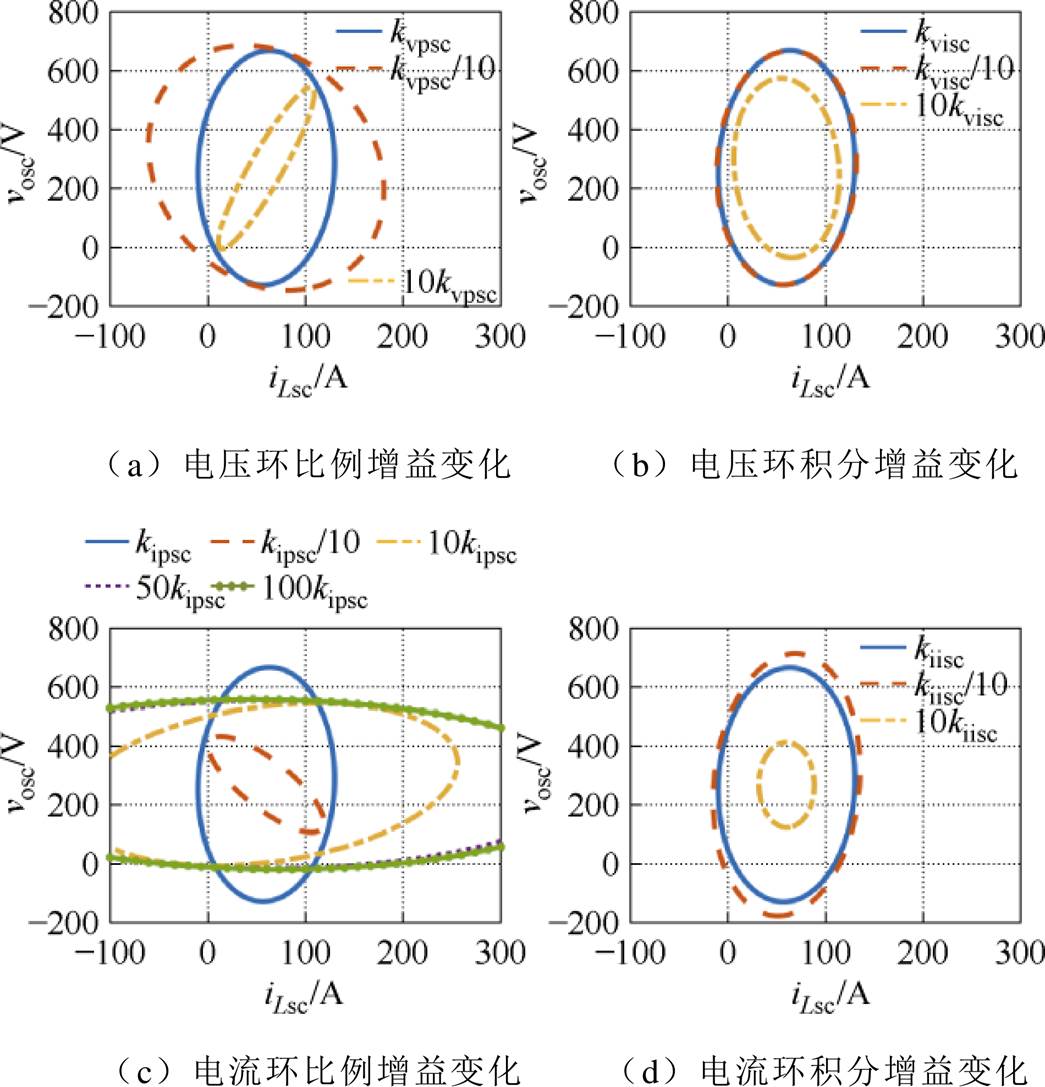
图6 超级电容变换器PI调节器参数变化对最大估计吸引域的影响
Fig.6 The impact of PI regulator parameter variations in SC converters on the largest estimated region of attraction
图7给出了系统带不同功率等级的恒功率负载时的最大估计吸引域,图中P1、P2和P3分别表示0 kW、3 kW和6 kW工作点。从图7中可以看出,随着功率等级的增大,吸引域在逐渐减小,并且吸引域的中心不断向右平移;此外,从7a中还可以看出,P1处在6 kW工作点的吸引域内,P3处在0 kW工作点的吸引域内,因此根据吸引域的定义,从0 kW工作点直接跳转到6 kW工作点和从6 kW工作点跳转到0 kW工作点都是稳定的。从图7b可以看出,当负载功率为30 kW时(脉冲负载加载),0 kW、3 kW和6 kW工作点均未被包含在30 kW的估计吸引域中,从0 kW、3 kW和6 kW跳转至30 kW都是不稳定的。因此,引入有源电容变换器吸收脉冲功率对维持供电系统稳定性尤为重要。在引入有源电容变换器后,脉冲功率全由有源电容部分吸收,此时整个混合电源系统的吸引域可仍由燃料电池、锂电池和超级电容组成的混合电源系统带0~6 kW恒功率负载的估计吸引域来表示。
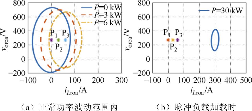
图7 系统带不同功率等级恒功率负载时对最大估计吸引域的影响
Fig.7 The Impact of the HPSS with CPL of different power levels on the largest estimated region of attraction
综上所述,HPSS正常运行时,在虚拟下垂控制参数中,FC变换器的阻性虚拟下垂参数Rvfc是主导的稳定参数;在PI调节器参数中,电压环和电流环的比例增益是主导的稳定参数;此外,功率等级变化也是主导的稳定参数。主导参数及其影响见表2。至此,可根据表2所示对主导参数进行优化设计,以提升HPSS的大信号稳定性。
表2 主导参数及其影响规律
Tab.2 Dominant parameters and their influence patterns
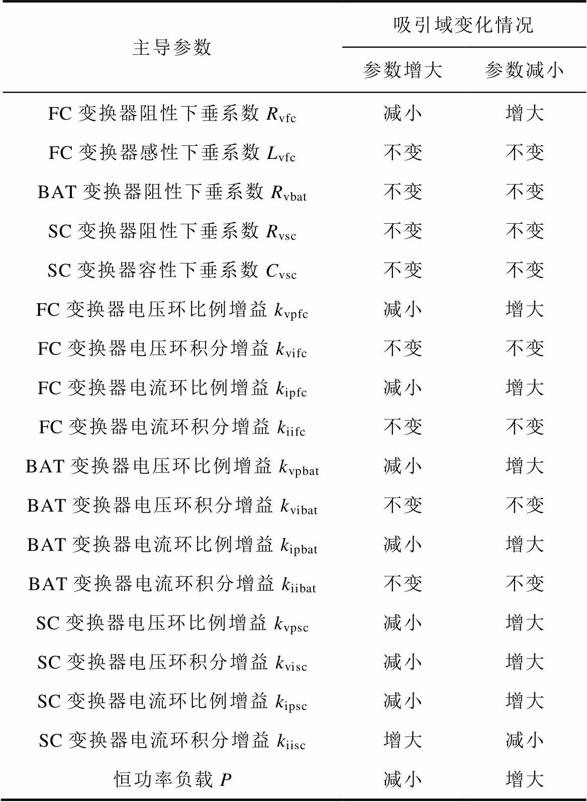
主导参数吸引域变化情况 参数增大参数减小 FC变换器阻性下垂系数Rvfc减小增大 FC变换器感性下垂系数Lvfc不变不变 BAT变换器阻性下垂系数Rvbat不变不变 SC变换器阻性下垂系数Rvsc不变不变 SC变换器容性下垂系数Cvsc不变不变 FC变换器电压环比例增益kvpfc减小增大 FC变换器电压环积分增益kvifc不变不变 FC变换器电流环比例增益kipfc减小增大 FC变换器电流环积分增益kiifc不变不变 BAT变换器电压环比例增益kvpbat减小增大 BAT变换器电压环积分增益kvibat不变不变 BAT变换器电流环比例增益kipbat减小增大 BAT变换器电流环积分增益kiibat不变不变 SC变换器电压环比例增益kvpsc减小增大 SC变换器电压环积分增益kvisc减小增大 SC变换器电流环比例增益kipsc减小增大 SC变换器电流环积分增益kiisc增大减小 恒功率负载P减小增大
为验证本文所提出的大信号稳定性分析方法的有效性及分析结果的正确性,基于图1所示HPSS架构在实验室搭建了6 kW FC-BAT-SC HPSS,并集成了最大功率为40 kW的有源电容变换器,实验平台如图8所示。
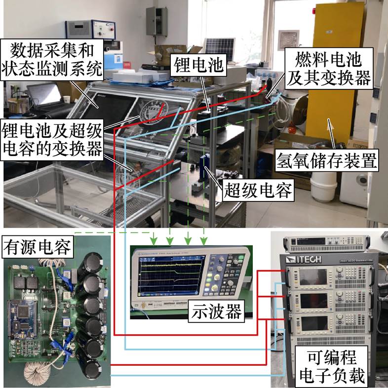
图8 燃料电池-锂电池-超级电容-有源电容混合供电系统实验平台
Fig.8 FC-BAT-SC-ACC HPSS experiment platform
图9和图10给出了不同虚拟阻抗下垂系数对系统稳定性的影响。从图9可以看出,随着FC变换器电阻下垂系数增大,母线电压开始振荡,并在空载到过载的阶跃变化过程中,动态过程振荡严重。而当虚拟电阻减小时,系统趋于稳定。从图10可以看出,SC变换器电容下垂系数变化对HPSS稳定性无明显影响。图9和图10的结果与图3所示的最大估计吸引域变化趋势一致。
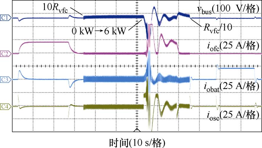
图9 燃料电池变换器电阻下垂系数变化对混合供电系统稳定性的影响实验结果
Fig.9 Experimental results on the impact of resistance droop coefficient variations in FC converters on HPSS stability
图11和图12描述了FC、BAT和SC变换器的电压电流环PI调节器积分增益变化对系统稳定性影响。从图中可以看出,积分增益变化时,系统稳定性无明显变化,这与图4~图6所示结果一致。
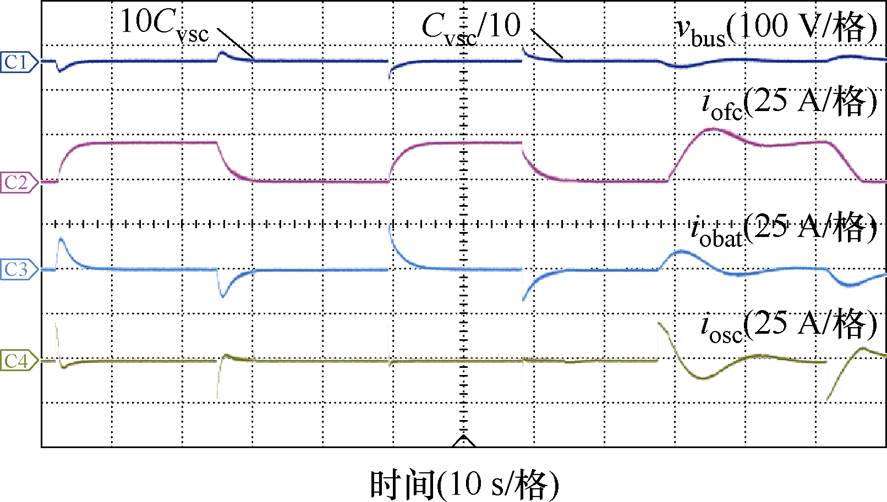
图10 超级电容变换器电容下垂参数变化对混合供电系统稳定性的影响实验结果
Fig.10 Experimental results on the impact of capacitance droop coefficient variations in SC converters on HPSS stability
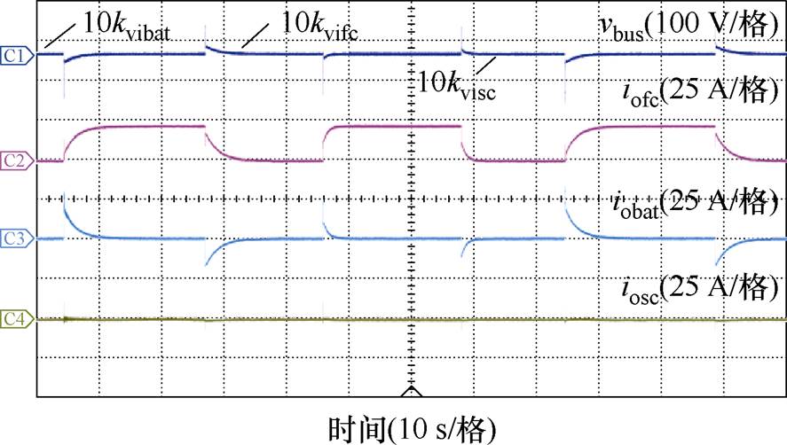
图11 燃料电池、锂电池和超级电容变换器电压环积分增益变化对混合供电系统稳定性的影响实验结果
Fig.11 Experimental results on the impact of voltage loop integral gain variations in FC converters, BAT converters, and SC converters on HPSS stability
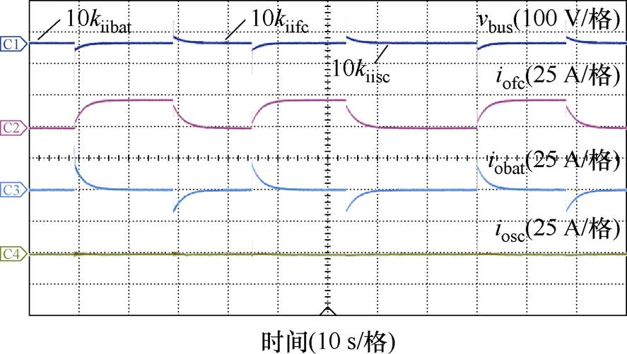
图12 燃料电池、锂电池和超级电容变换器电流环积分增益变化对混合供电系统稳定性的影响实验结果
Fig.12 Experimental results on the impact of current loop integral gain variations in FC converters, BAT converters, and SC converters on HPSS stability
图13~图15展示了PI调节器比例增益的变化对系统稳定性的影响。从图中可以看出,随着FC和BAT的PI调节器电压和电流环中比例增益的增加,系统的稳定性下降,而SC变换器的PI控制器比例增益的增加对系统的稳定性影响较小。这与图4~图6所示结果一致。因此,参数变化对最大估计吸引域的影响得到了充分验证。
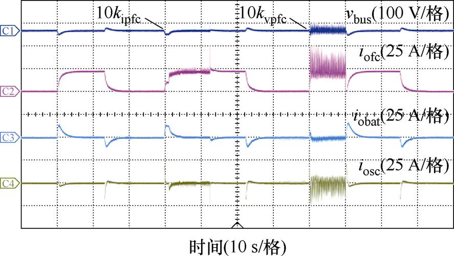
图13 燃料电池变换器电压环和电流环比例增益变化对混合供电系统稳定性的影响实验结果
Fig.13 Experimental results on the impact of voltage loop and current loop proportional gain variations in FC converters on the stability of the HPSS
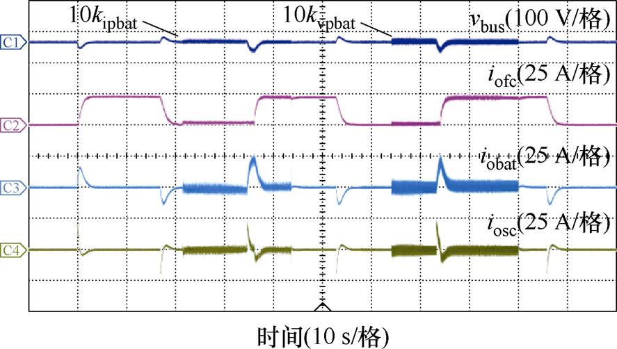
图14 锂电池变换器电压环和电流环比例增益变化对混合供电系统稳定性的影响实验结果
Fig.14 Experimental results on the impact of voltage loop and current loop proportional gain variations in BAT converters on the stability of the HPSS
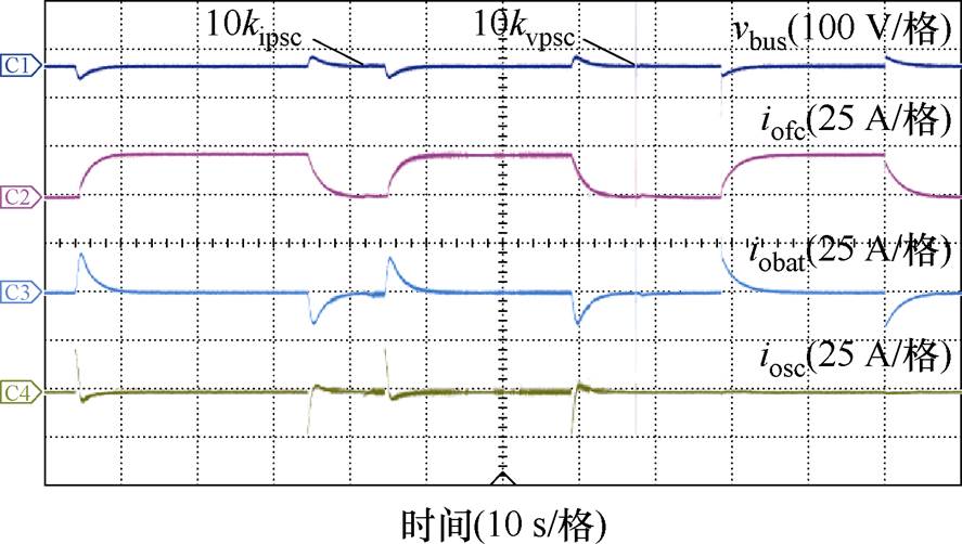
图15 超级电容变换器电压环和电流环比例增益变化对混合供电系统稳定性的影响实验结果
Fig.15 Experimental results on the impact of voltage loop and current loop proportional gain variations in SC converters on the stability of the HPSS
根据参数变化对估计吸引域的影响,最终选取了合适的控制参数见表1,并对负载切换过程进行了实验验证,负载从0 kW到6 kW和从6 kW到0 kW的实验结果如图16所示。从图16中可以看出,参数优化可使系统在空载和过载之间切换时具有较好的动静态性能。
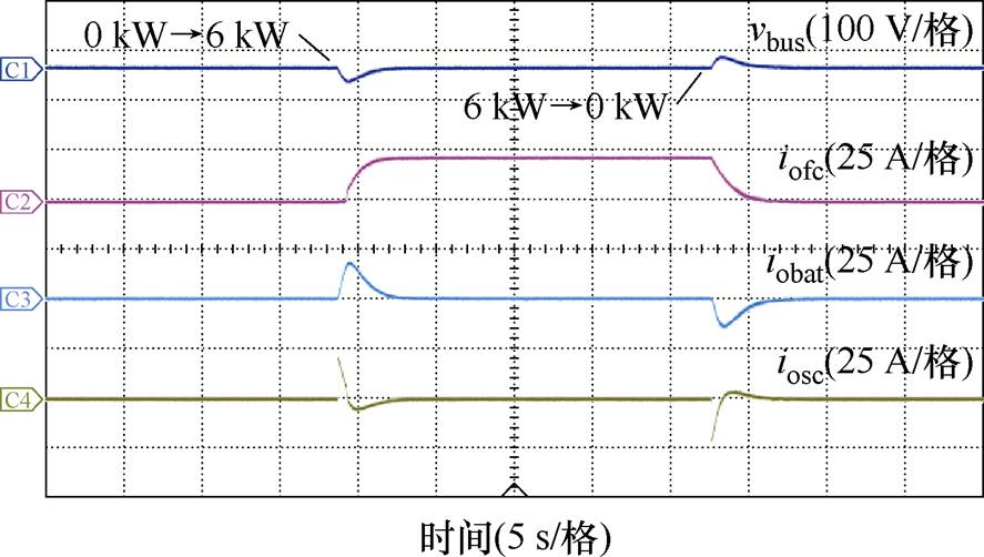
图16 负载从0 kW到6 kW和从6 kW到 0 kW的实验结果
Fig.16 Experimental results of load step changes between 0 kW and 6 kW
图17描述了脉冲负载加载后HPSS(未引入有源电容变换器)的动态性能。从图17中可以看出,HPSS在3 ms后失稳。图18给出了引入有源电容变换器后脉冲负载加载后HPSS的动态性能。从图18中可以看出,HPSS母线仅出现小幅波动,系统始终保持稳定,这与图7所示结果一致。验证了有源电容变换器对于提升脉冲负载作用下系统大信号稳定的优良效果。
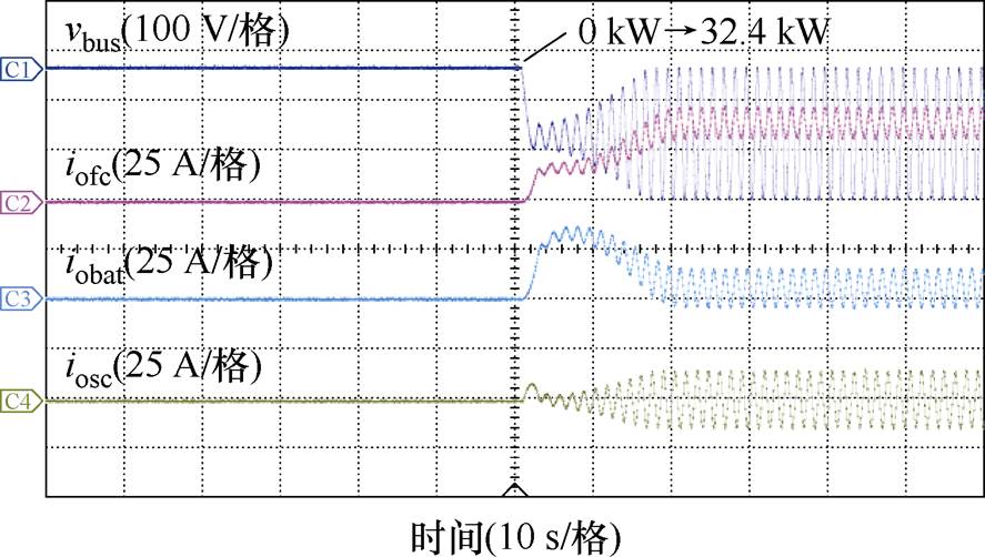
图17 未引入有源电容变换器情况下负载由 0 kW跳转至32.4 kW的实验结果
Fig.17 Experimental results of load step change from 0 kW to 32.4 kW without the ACC
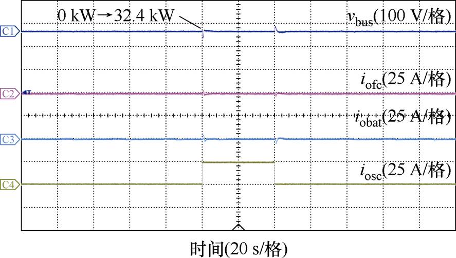
图18 引入有源电容变换器后负载由0 kW跳转至32.4 kW的实验结果
Fig.18 Experimental results of load step change from 0 kW to 32.4 kW with the ACC
本文对含脉冲负载的FC-BAT-SC HPSS的大信号稳定性分析问题进行了详尽的研究。考虑到基于混合势函数理论及平方和规划法无法实现考虑控制动态的高阶系统大信号稳定性分析,首先构建了计及控制动态的混合供电系统T-S模糊模型,在此基础上进行了基于吸引域估计的大信号稳定性分析。详细探讨了控制参数和负载功率等级变化对估计吸引域的影响。理论分析和实验结果表明,阻性下垂系数和PI调节器的比例增益是影响系统稳定性的主要参数,可通过优化这些参数来提高系统的稳定性。此外,高峰均比脉冲负载也会引起系统失稳,可引入有源电容对脉冲负载进行功率解耦,提升系统稳定性。最后通过实验验证,系统在无ACC进行大负载投切后3 ms后失稳,而在有ACC进行大负载投切时,系统经过小幅度波动后恢复稳定。所提大信号稳定性分析方法可推广应用于多源混合供电系统的性能分析,实现失稳预判,指导参数优化。
附 录
 (A1)
(A1)
 (A1续)
(A1续)
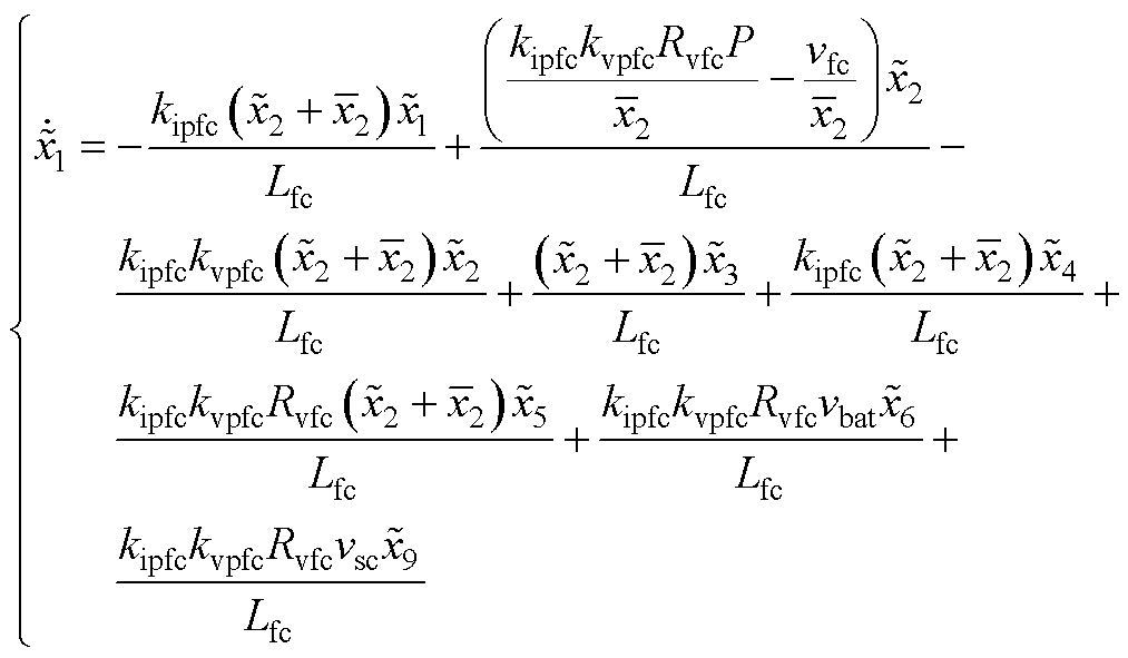 (A2)
(A2)
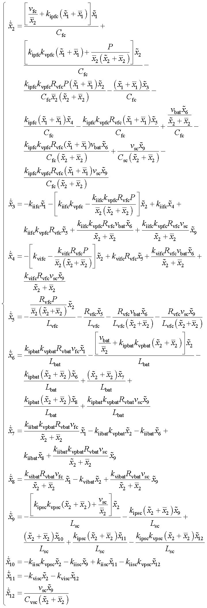 (A2续)
(A2续)
参考文献
[1] 刘偲艳, 葛庆. 氢燃料汽车混合动力系统能量管理优化策略[J]. 电气技术, 2024, 25(9): 22-26.
Liu Siyan, Ge Qing. Energy management optimization strategy for hydrogen fuel vehicle hybrid power system[J]. Electrical Engineering, 2024, 25(9): 22-26.
[2] 敖文杰, 陈家伟, 陈杰, 等. 燃料电池-锂电池混合供电系统的无源控制策略及参数设计方法[J]. 电工技术学报, 2024, 39(2): 580-594.
Ao Wenjie, Chen Jiawei, Chen Jie, et al. Passivity- based control strategy and parameter design method for fuel cell-lithium battery hybrid power supply system[J]. Transactions of China Electrotechnical Society, 2024, 39(2): 580-594.
[3] 高锋阳, 高翾宇, 张浩然, 等. 全局与瞬时特性兼优的燃料电池有轨电车能量管理策略[J]. 电工技术学报, 2023, 38(21): 5923-5938.
Gao Fengyang, Gao Xuanyu, Zhang Haoran, et al. Management strategy for fuel cell trams with both global and transient characteristics[J]. Transactions of China Electrotechnical Society, 2023, 38(21): 5923- 5938.
[4] 高锋阳, 苏红宇, 查鹏堂, 等. 基于工况预测和动力源寿命衰减协同的燃料电池有轨电车能量管理策略[J]. 电工技术学报, 2025, 40(13): 4316-4329.
Gao Fengyang, Su Hongyu, Zha Pengtang, et al. Energy management strategy for fuel cell hybrid tram system based on driving cycle prediction and power source lifespan decay synergy[J]. Transactions of China Electrotechnical Society, 2025, 40(13): 4316- 4329.
[5] 严锐浩, 许亮. 基于模糊控制优化小波分解的FCHEV能量管理策略[J/OL]. 电源学报, 1-12[2025- 09-01]. https://link.cnki.net/urlid/12.1420.tm.20240425. 1853.034.
Yan Ruihao, Xu Liang. Fuzzy control based opti- mized wavelet decomposition for FCHEV energy management strategy[J/OL]. Journal of Power Supply, 1-12[2025-09-01]. https://link.cnki.net/urlid/12.1420. tm.20240425.1853.034.
[6] 宋清超, 陈家伟, 蔡坤城, 等. 多电飞机用燃料电池-蓄电池-超级电容混合供电系统的高可靠动态功率分配技术[J]. 电工技术学报, 2022, 37(2): 445-458.
Song Qingchao, Chen Jiawei, Cai Kuncheng, et al. A highly reliable power allocation technology for the fuel cell-battery-supercapacitor hybrid power supply system of a more electric aircraft[J]. Transactions of China Electrotechnical Society, 2022, 37(2): 445-458.
[7] 郝艺, 周瑀涵, 刘晨曦, 等. 含跟网型储能的新能源多馈入系统小扰动电压支撑强度分析[J]. 电工技术学报, 2024, 39(11): 3569-3580.
Hao Yi, Zhou Yuhan, Liu Chenxi, et al. Small- disturbance voltage support strength analysis for renewable multi-infeed system with grid-following energy storage[J]. Transactions of China Electro- technical Society, 2024, 39(11): 3569-3580.
[8] Xu Qianwen, Wang Peng, Chen Jiawei, et al. A module-based approach for stability analysis of complex more-electric aircraft power system[J]. IEEE Transactions on Transportation Electrification, 2017, 3(4): 901-919.
[9] Yang Dongsheng, Sun Yin. SISO impedance-based stability analysis for system-level small-signal stability assessment of large-scale power electronics- dominated power systems[J]. IEEE Transactions on Sustainable Energy, 2022, 13(1): 537-550.
[10] 孙秋野, 李大双, 王睿, 等. “双高”电力系统: 一种新的稳定判据和稳定性分类探讨[J]. 中国电机工程学报, 2024, 44(8): 3016-3036.
Sun Qiuye, Li Dashuang, Wang Rui, et al. Power system with high shares of renewables and power electronics: a new stability criterion and classifica- tion[J]. Proceedings of the CSEE, 2024, 44(8): 3016-3036.
[11] Zhang Chen, Molinas M, Rygg A, et al. Impedance- based analysis of interconnected power electronics systems: impedance network modeling and com- parative studies of stability criteria[J]. IEEE Journal of Emerging and Selected Topics in Power Elec- tronics, 2020, 8(3): 2520-2533.
[12] He Bangbang, Chen Wu, Zhang Chun, et al. Impedance- based stability of grid-connected DC distribution power systems: AC- and DC-side stability criteria, equivalence, and difference[J]. IEEE Journal of Emerging and Selected Topics in Power Electronics, 2023, 11(6): 5842-5852.
[13] Brayton R K, Moser J K. A theory of nonlinear networks. I[J]. Quarterly of Applied Mathematics, 1964, 22(1): 1-33.
[14] Jarvis-Wloszek Z W. Lyapunov based analysis and controller synthesis for polynomial systems using sum-of-squares optimization[D]. Berkeley, CA, USA: University of California, Berkeley, 2003.
[15] Takagi T, Sugeno M. Fuzzy identification of systems and its applications to modeling and control[J]. Readings in Fuzzy Sets for Intelligent Systems, 1993: 387-403.
[16] Jiang Jianbo, Liu Fei, Pan Shangzhi, et al. A conservatism-free large signal stability analysis method for DC microgrid based on mixed potential theory[J]. IEEE Transactions on Power Electronics, 2019, 34(11): 11342-11351.
[17] Chang Fangyuan, Cui Xiaofan, Wang Mengqi, et al. Large-signal stability criteria in DC power grids with distributed-controlled converters and constant power loads[J]. IEEE Transactions on Smart Grid, 2020, 11(6): 5273-5287.
[18] Song Qingchao, Chen Jiawei, Loo K H, et al. Large-signal stability analysis of two-stage cascaded DC/DC converter systems using sum-of-squares programming[J]. IEEE Transactions on Power Elec- tronics, 2024, 39(2): 2076-2085.
[19] Liu Zhangjie, Ge Xin, Su Mei, et al. Complete large-signal stability analysis of DC distribution network via brayton-moser’s mixed potential theory[J]. IEEE Transactions on Smart Grid, 2023, 14(2): 866-877.
[20] Papachristodoulou A, Prajna S. A tutorial on sum of squares techniques for systems analysis[C]// Proceedings of the 2005, American Control Con- ference, 2005, Portland, OR, USA, 2005: 2686-2700.
[21] Severino B, Strunz K. Enhancing transient stability of DC microgrid by enlarging the region of attraction through nonlinear polynomial droop control[J]. IEEE Transactions on Circuits and Systems I: Regular Papers, 2019, 66(11): 4388-4401.
[22] Guthrie J. Large-signal stability analysis of pulsed constant power loads via sum-of-squares optimi- zation[C]//2019 IEEE Electric Ship Technologies Symposium (ESTS), Washington, DC, USA, 2019: 127-133.
[23] Topcu U, Packard A, Seiler P. Local stability analysis using simulations and sum-of-squares program- ming[J]. Automatica, 2008, 44(10): 2669-2675.
[24] Reznick B. Some concrete aspects of Hilbert's 17th problem[J]. Contemporary mathematics, 2000, 253:
251-272.
[25] Zheng Huajun, Yuan Xufeng, Cai Jie, et al. Large- signal stability analysis of DC side of VSC-HVDC system based on estimation of domain of attraction[J]. IEEE Transactions on Power Systems, 2022, 37(5): 3630-3641.
[26] 明佳, 王玉斌, 王璠, 等. 直流微网的大信号稳定性分析及有源阻尼补偿方法[J]. 电工技术学报, 2021, 36(增刊2): 517-529.
Ming Jia, Wang Yubing, Wang Fan, et al. Large- signal stability analysis and active damping com- pensation methods for DC microgrid[J]. Transactions of China Electrotechnical Society, 2021, 36(S2): 517-529.
[27] Duan Ziyue, Meng Yongqing, Duan Yunkang, et al. Large-signal stability analysis and enhancement of modular multilevel matrix converter under power fluctuation based on T-S fuzzy model theory[J]. IEEE Transactions on Power Electronics, 2023, 38(11): 14601-14613.
[28] Liu Sucheng, Li Xiang, Xia Mengyu, et al. Takagi- sugeno multimodeling-based large signal stability analysis of DC microgrid clusters[J]. IEEE Transa- ctions on Power Electronics, 2021, 36(11): 12670- 12684.
[29] Chen Jiawei, Chen Jie. Stability analysis and parameters optimization of islanded microgrid with both ideal and dynamic constant power loads[J]. IEEE Transactions on Industrial Electronics, 2018, 65(4): 3263-3274.
[30] Huang Xinze, Ruan Xinbo, Du Fangjun, et al. A pulsed power supply adopting active capacitor converter for low-voltage and low-frequency pulsed loads[J]. IEEE Transactions on Power Electronics, 2018, 33(11): 9219-9230.
Abstract Hybrid power supply systems (HPSS) can fully leverage the characteristics of different power sources to enhance the power supply performance of electrified transportation systems. However, extreme operating conditions of large-scale load switching can easily induce system instability. Traditional small-signal stability analysis methods struggle to address these large-disturbance scenarios comprehensively. This paper investigates the large-signal stability analysis of HPSS considering control dynamics based on the largest region of attraction (ROA). The impacts of control parameters and load power variations on HPSS large-signal stability are examined, and a stability enhancement scheme is proposed utilizing an active capacitor converter (ACC) to absorb pulsed power. The research reveals that resistance droop coefficients, proportional gains of PI regulators in the voltage and current loops, and load power constitute dominant instability characteristics in HPSS. Optimization of control parameters can expand the system's ROA, thereby achieving greater stability margins.
Firstly, the main circuit model of the HPSS is constructed using the state average method. A control strategy combining virtual droop control and dual-loop PI control is employed to achieve dynamic power sharing, leading to the derivation of the mathematical model considering control dynamics. An ACC is integrated into the HPSS to decouple the high peak-to-average pulse power load. Notably, the voltage control loop of ACC is not employed for bus voltage regulation, but rather for the restoration of the energy storage capacitor voltage. Therefore, during pulse load operation, ACC can be equivalent to a current source that supplies instantaneous pulse current. It ensures zero energy interaction between ACC and HPSS while operating as a conventional load under non-pulse durations. Consequently, ACC can be considered a traditional load when conducting large-signal stability analysis. Therefore, a comprehensive HPSS state-space model for large-signal stability analysis incorporating control dynamics can be formulated without ACC. After that, the T-S fuzzy modeling method is employed to transfer the HPSS state-space model into a T-S fuzzy model, and then the largest ROA can be obtained through Lyapunov stability theory and linear matrix inequality (LMI) optimization. The most significant ROA estimation results reveal three dominant stability parameters: (1) The resistance droop coefficient (Rvfc) of the FC converter. (2) Proportional gains in both voltage and current loops of PI regulators of DC-DC converters. (3) Load power level variations.
An experimental platform of HPSS incorporating FC, BAT, SC, and ACC was established in the lab. The experimental measurements demonstrate excellent agreement with the theoretical predictions derived from the largest ROA estimation-based stability analysis. Moreover, the HPSS exhibited instability within tens of milliseconds when the pulse power load is activated without ACC, while the HPSS remained stable with merely minor bus voltage fluctuations after integrating ACC.
The following conclusions can be made. (1) The resistive droop coefficient and the proportional gain of the PI regulator are the primary parameters affecting system stability. (2) ACC-enabled power decoupling for pulse power loads significantly enhances system stability.
keywords:Large-signal stability, region of attraction, hybrid power supply system, pulsed power load, virtual impedance droop control
DOI: 10.19595/j.cnki.1000-6753.tces.250546
中图分类号:TM46
收稿日期 2025-04-04
改稿日期 2025-05-09
陈志跃 男,2000年生,硕士研究生,研究方向为电力电子变换器稳定性分析及控制。E-mail: zhiyuechen@cqu.edu.cn
陈家伟 男,1986年生,教授,博士生导师,研究方向为电气化交通技术、新能源发电与微电网技术等。E-mail: echenjw@cqu.edu.cn(通信作者)
(编辑 陈 诚)