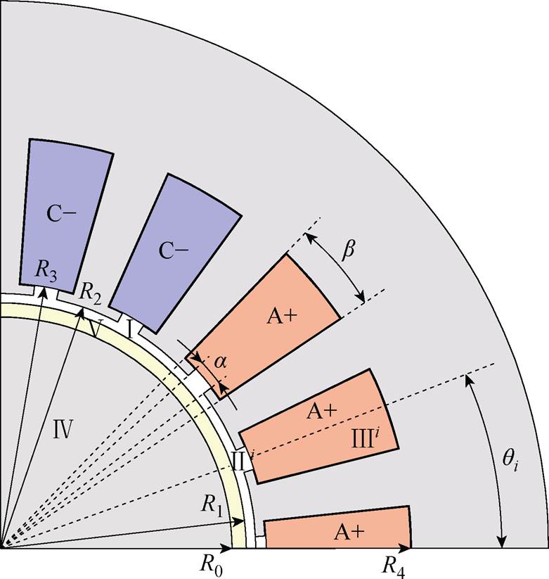
图1 覆铜实心转子感应电机子域模型
Fig.1 The subdomain model of copper-coated solid rotor induction motors
摘要 覆铜实心转子感应电机的转子磁场分布复杂,采用传统集总参数磁路分析法无法展示电机内的磁场分布,也难以考虑转差率对等效电路参数的影响。对此,该文以求解覆铜实心转子内电磁场为目标,使用柱坐标下的子域解析法,充分考虑定子开槽、槽口形状对电磁场的影响,对气隙、转子铜层和转子铁心电磁场进行解析计算,并通过二维涡流场有限元进行验证。相比有限元法,解析法选择适当的谐波次数能够大幅缩短计算时间。针对覆铜实心转子感应电机,对比分析了子域解析法与传统波阻抗法的等效电路模型及其输入阻抗参数与输出特性。结果表明,相较于传统波阻抗法,子域解析法在不同转差率条件下均与有限元计算结果具有更高的一致性。
关键词:覆铜实心转子感应电机 子域解析法 电磁场分布 波阻抗法 等效电路
实心转子相比叠片转子具有更高的转子强度,更适合高速应用[1],实心转子感应电机在大功率、超高速领域具有独特优势。覆铜实心转子感应电机是在实心转子感应电机基础上增加转子表面铜层结构,目的是提升实心转子电机电磁性能[2-3]。与传统笼型和绕线式转子不同,覆铜实心转子没有显性绕组结构,因此难以通过转子尺寸直接得到转子阻抗参数。并且受转子实心体内趋肤效应的影响,转子内电磁场分布及转子阻抗参数随转差率变化较 大[4-6]。传统磁路分析法主要针对转子阻抗随转差率变化不明显的集总参数电路,因此不适用覆铜实心转子感应电机。为了明确覆铜实心转子感应电机内电磁场分布情况及电机等效电路参数,需要对电机进行电磁场解析计算。
从实心转子结构被提出以来,国内外学者针对电机磁场解析计算模型和等效电路进行了大量研究。其中有两种解析计算模型被学界广泛认可和采纳,分别为直角坐标系下忽略定子开槽效应的子域解析法[4, 7-8]和将转子分为多层结构的传递矩阵法[9-12]。直角坐标系下忽略定子开槽效应的子域解析法在快速估算实心转子电机性能方面具有优势,但忽略了定子齿槽谐波的影响,无法计及磁场谐波对电机的影响[13],且在直角坐标系下难以考虑转子曲率对磁场分布的影响,特别在转子半径较小的情况下,误差增加。多层传递矩阵法的特点是能够考虑转子饱和对电机性能的影响,但其同样忽略了定子开槽效应,只考虑基波磁场的作用,且转子所分层数对计算精度有较大影响。这两种方法都是基于实心转子表面波阻抗理论[4]求解实心转子阻抗,不能考虑到谐波磁场的影响,对于谐波磁场影响较小的模型(如大气隙)能够取得较高精度,但当谐波磁场不能忽略时,计算精度降低。
为解决忽略磁场谐波与转子曲率造成的解析模型精度不高的问题,文献[14-18]提出了在二维坐标下的子域解析模型,这种方法首先被应用在解析计算表贴式永磁同步电机磁场,随后拓展至磁场调制永磁电机、多相永磁电机、磁齿轮等模型。随着实心转子感应电机在高速直驱系统中的应用,柱坐标系下考虑定子齿槽效应的子域解析法被应用在实心转子感应电机磁场解析计算中[19-22]。文献[19]将直角坐标系转化为圆柱坐标系,消除了转子曲率的影响,但仍然忽略了定子开槽。文献[20]考虑了定子开槽效应的影响,但未充分考虑定子槽口形状对磁场谐波的影响,且未对电机等效电路参数解析计算。文献[21]对定子开槽及槽口形状做了精确建模,但转子拓扑仅为光滑实心结构,且缺乏同步工况下的磁场解析推导。文献[22]提出的简化子域法在小转差率下计算误差较小,但大转差率下准确性下降。
本文首次提出了覆铜实心转子感应电机考虑定子开槽的子域解析模型,并充分考虑槽口形状的影响,在电机同步和异步运行时推导槽子域、槽口子域、气隙子域、转子铜层子域、转子铁心子域内的电磁场分布情况,将转子内磁力线分布采用解析法直观呈现出来,并研究了不同谐波次数对解析计算时间的影响。以磁场解析计算结果推导了等效电路参数计算公式并与传统波阻抗法计算等效电路参数进行了对比。相比波阻抗模型计算阻抗参数,本文所提方法充分考虑了谐波磁场的影响,对于谐波磁场较大的大转差率工况仍然能保持较高的准确性。
为便于将电机尺寸表示为柱坐标的形式,将电机定子齿部、槽部、绕组形状简化为同心圆的扇形结构,如图1覆铜实心转子感应电机子域模型所示。电机分为5个子域,分别为气隙子域Ⅰ、槽口子域Ⅱi、槽子域Ⅲi、转子铁心子域Ⅳ、转子铜层子域Ⅴ。其中,i表示第i个定子槽,第i个定子槽中心线与转子初始位置的夹角为qi。定子槽口夹角为a,定子槽载流部分夹角为b。定子槽内ABC三相绕组采用+、-表示电流流出和流入纸面方向。R0为转子铁心外径,R1为转子铜层外径,R2为定子内径,R3为定子槽载流部分内径,R4为定子槽载流部分外径。
图1 覆铜实心转子感应电机子域模型
Fig.1 The subdomain model of copper-coated solid rotor induction motors
二维子域法求解电机内磁场的假设条件:
(1)电机轴向长度无限长,即忽略电机的端部效应。
(2)定子铁心磁导率为无穷大,电导率为0。转子铁心、转子铜层磁导率、电导率为恒定值且各向同性。
(3)转子铁心和转子铜层内电流只有轴向分量。
(4)电机电磁场变化为正弦,忽略材料磁场饱和的影响。
引入柱坐标下的矢量磁位A(r, q),其中,r、q分别为半径和角度,则磁感应强度B(r,q)的径向分量和切向分量可分别表示为
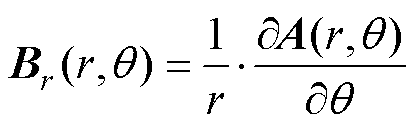 (1)
(1)
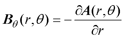 (2)
(2)
轴向电流密度可表示为
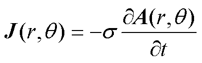 (3)
(3)
式中,s为求解域内的材料电导率;t为时间。
为避免求取谐波系数出现病态矩阵,参考法国学者T. Lubin等提出的系数放缩理论[23],引入Pn(x, y)和En(x, y)两个函数对谐波系数放缩,其中,x和y为函数自变量,n为气隙磁场谐波次数。
 (4)
(4)
 (5)
(5)
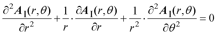
气隙子域Ⅰ的矢量磁位AⅠ适用于拉普拉斯方程,有
 (6)
(6)
 (7)
(7)
 (8)
(8)
采用分离变量法对上述拉普拉斯方程进行求解,可得到气隙子域矢量磁位的通解为
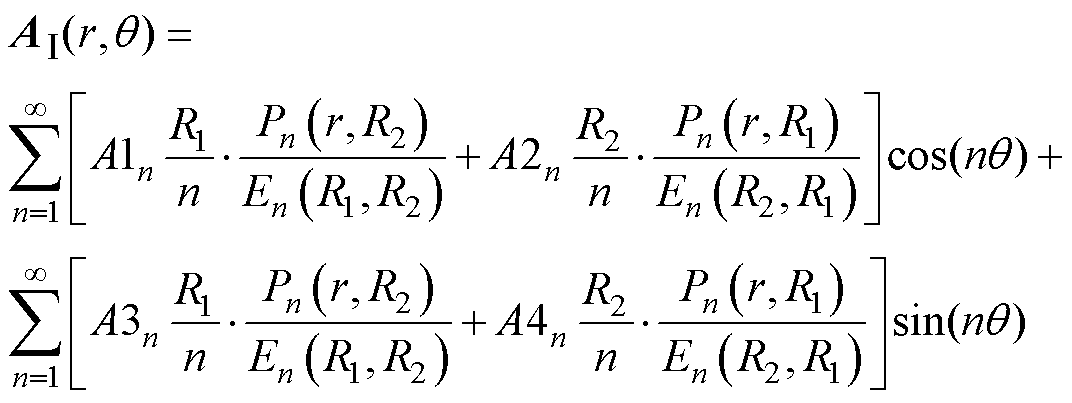 (9)
(9)
式中,A1n、A2n、A3n、A4n为气隙磁场谐波系数。
槽口子域Ⅱi的矢量磁位为 ,拉普拉斯方程为
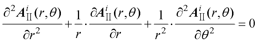 (10)
(10)
 (11)
(11)
 (12)
(12)
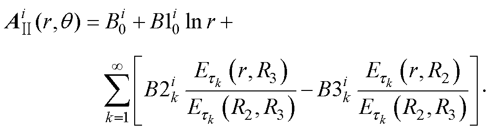
采用分离变量法对上述拉普拉斯方程进行求解,得到槽口子域矢量磁位的通解为
 (13)
(13)
 (14)
(14)
式中, 、
、 、
、 、
、 为槽口磁场谐波系数;k为槽口磁场谐波次数。
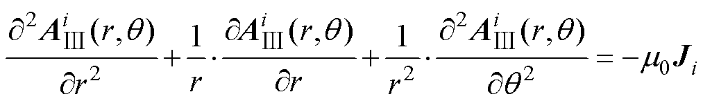
槽子域Ⅲi的矢量磁位 有泊松方程为
 (15)
(15)
 (16)
(16)
 (17)
(17)
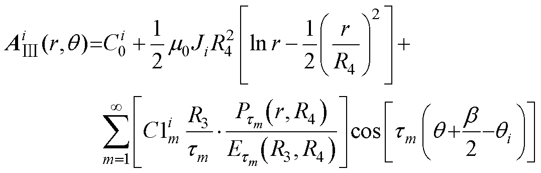
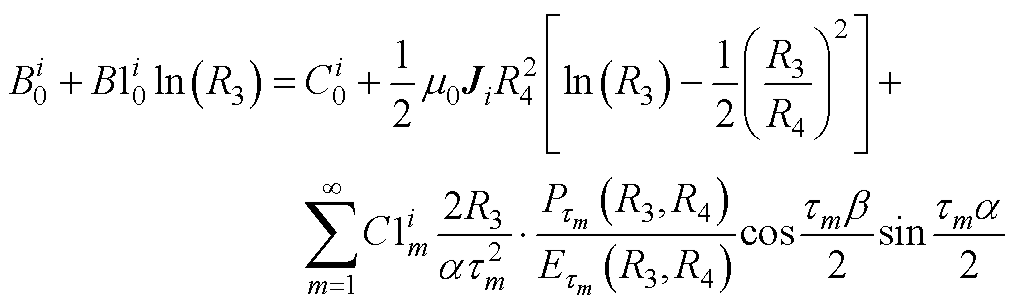
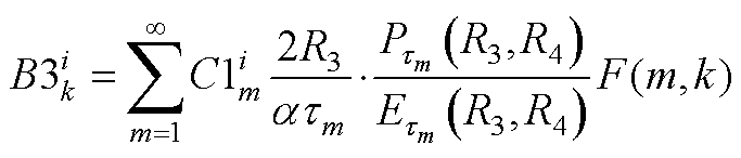
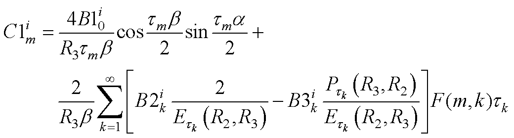
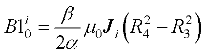
式中,m0为真空磁导率;Ji为第i槽内电流密度。采用分离变量法对上述泊松方程进行求解,得到槽子域矢量磁位的通解为
 (18)
(18)
 (19)
(19)
式中, 、
、 为槽内磁场谐波系数;m为槽子域磁场谐波次数。
异步运行时,转子铁心子域Ⅳ的磁矢量磁位AⅣ满足磁场扩散方程,有
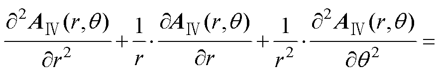
 (20)
(20)
 (21)
(21)
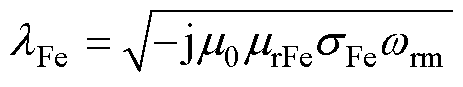
(22)
式中,mrFe、sFe分别为转子铁心相对磁导率和电导率;wrm为转子内涡流的电角速度,wrm=sw,其中s为转差率,w=2pf为定子电源角速度,f为电源频率。
求解式(20)可得转子铁心子域矢量磁位通解为
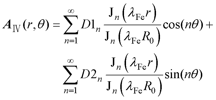 (23)
(23)
式中,D1n、D2n为转子铁心磁场谐波系数;Jn为n阶第一类贝塞尔函数;lFe为转子铁心透入深度相关的系数。
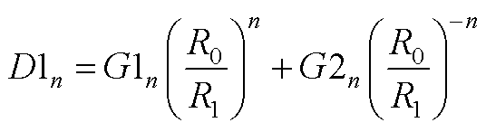
同步运行时,转子内不存在感应涡流,式(20)等式右侧为零,转子铁心矢量磁位通解为
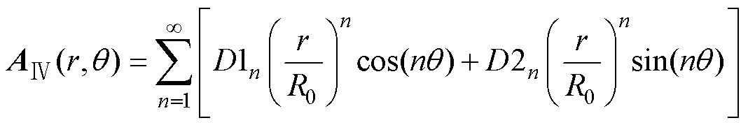 (24)
(24)
 (25)
(25)
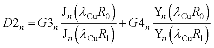
异步运行时,转子铜层子域Ⅴ的磁矢量磁位AⅤ由磁场扩散方程可得
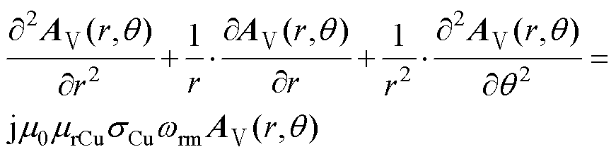 (26)
(26)
 (27)
(27)
(28)
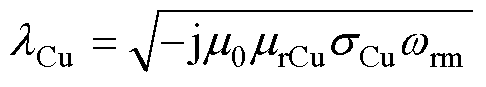
式中,mrCu、sCu分别为转子铜层相对磁导率和电导率。
转子铜层子域矢量磁位通解为
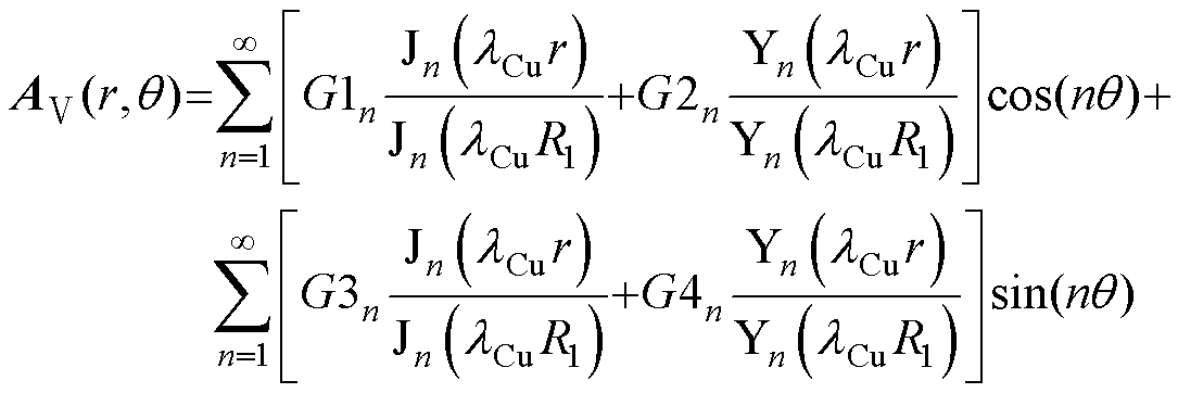 (29)
(29)
式中,G1n、G2n、G3n、G4n为转子铜层磁场谐波系数;Yn为n阶第二类贝塞尔函数;lCu为转子铜层透入深度相关的系数。
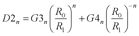
同步运行时,式(26)等式右侧为零,转子铜层子域矢量磁位通解为
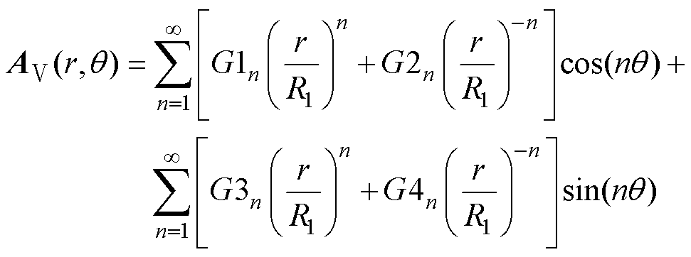 (30)
(30)
 (31)
(31)
 (32)
(32)
 (33)
(33)
 (34)
(34)
 (35)
(35)
 (36)
(36)
 (37)
(37)
 (38)
(38)
 (39)
(39)
将式(9)和式(13)代入式(32)和式(33),得
 (40)
(40)
 (41)
(41)
 (42)
(42)
 (43)
(43)
将式(9)和式(29)、式(30)代入式(34)和式(35)得
 (44)
(44)
 (45)
(45)
 (46)
(46)
 (47)
(47)
将式(13)和式(18)代入式(36)和式(37)得
 (48)
(48)
 (49)
(49)
 (50)
(50)
 (51)
(51)
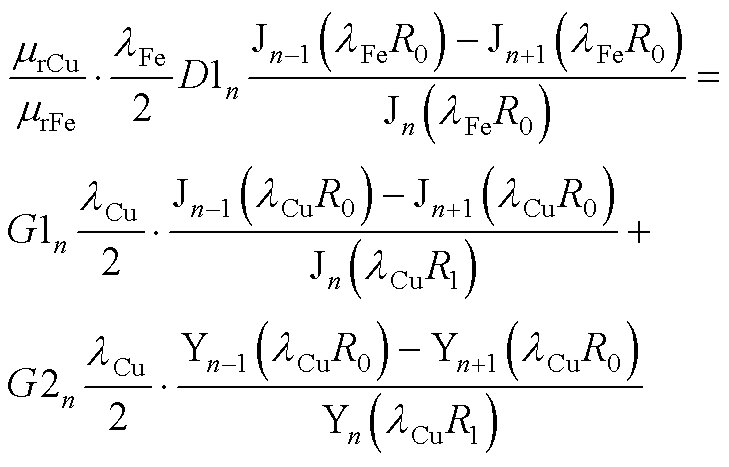
将式(23)、式(24)和式(29)、式(30)代入式(38)和式(39)得
 (52)
(52)
 (53)
(53)
 (54)
(54)
 (55)
(55)
 (56)
(56)
 (57)
(57)
式中,式(54)和式(56)为异步运行时的系数方程;式(55)和式(57)为同步运行时的系数方程; 和
和 分别为Jn和Yn的一阶导数。
A1n、A2n、A3n、A4n、、、 、、、
、、、 、D1n、D2n、G1n、G2n、G3n、G4n,共16个谐波系数的求解过程参考附录。
以一台2极18槽覆铜实心转子感应电机模型为例,对电机在空载和负载情况下的气隙磁通密度、转子磁力线分布、转子电流分布进行解析计算,并将解析结果与有限元计算对比。电机的主要尺寸参数见表1。
表1 覆铜实心转子感应电机的主要尺寸和参数
Tab.1 Main dimensions and parameters of copper-coated solid rotor induction motor
参 数数值 转子铁心外径R0/mm24.5 转子铜层外径R1/mm26 定子内径R2/mm27 定子槽载流部分内径R3/mm28 定子槽载流部分外径R4/mm43.5 轴向长度Lef/mm50 槽口夹角a/rad5p/180 槽载流部分夹角b/rad12p/180 转子铁心相对磁导率mrFe200 转子铁心电导率sFe/(S/m)5 000 000 转子铜层相对磁导率mrCu1 转子铜层电导率sCu/(S/m)47 600 000 极对数p1 定子槽数Q18 每槽导体数Nc45 并联支路数a1 定子相电阻Rs/W2.676 相电流幅值Imax/A8.5 相电压幅值Um/V311 电流频率f/Hz200
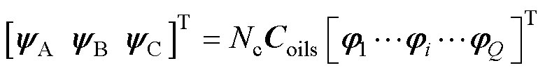
定子绕组为单层绕组,排布形式为A+A+A+C- C-C-B+B+B+,用向量表示为
 (58)
(58)
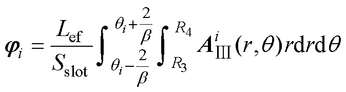
第i槽内电流密度可表示为
 (59)
(59)
其中
 (60)
(60)
式中,Sslot为每槽截面积; 为矩阵
为矩阵 的转置。
的转置。
将n, m, k分别取120, 5, 5。通过上述磁场解析式(40)~式(57)即可求得电机在不同运行状态下的气隙磁通密度、磁力线分布、转子涡流分布情况。
(1)当转差率s=0时,感应电机处于同步运行状态。电机在气隙中心处Rd=(R1+R2)/2的径向和切向复磁通密度为
 (61)
(61)
 (62)
(62)
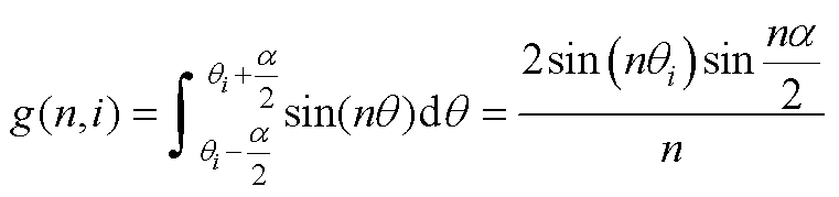
求解式(61)和式(62)的实部得气隙磁通密度的径向、切向值如图2、图3所示。转子内磁力线分布由转子铁心矢量磁位实部Re[AⅣ(r,q)]和转子铜层矢量磁位实部Re[AⅤ(r, q)]求等高线得到,如图4所示。
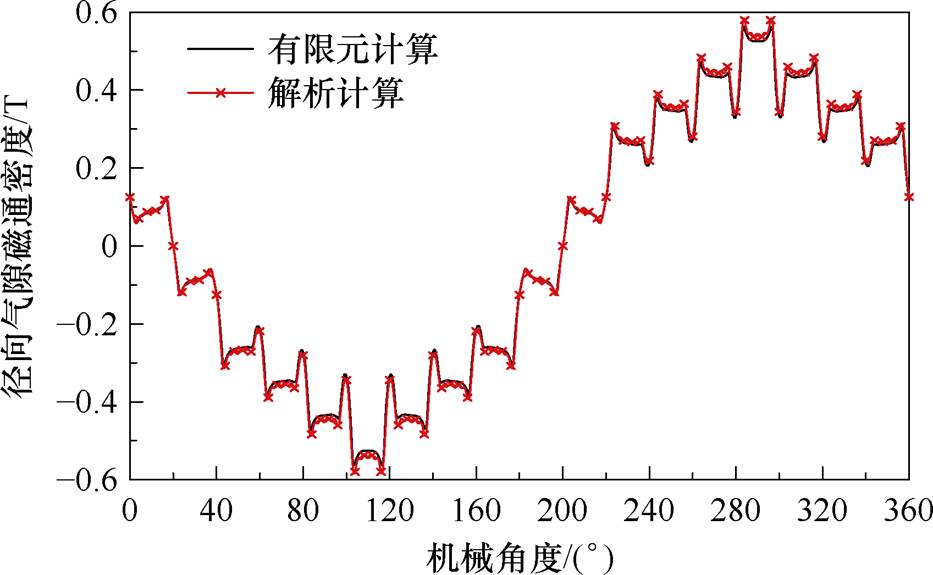
图2 径向气隙磁通密度(s=0, r=Rd)
Fig.2 Radial airgap flux density (s=0, r=Rd)
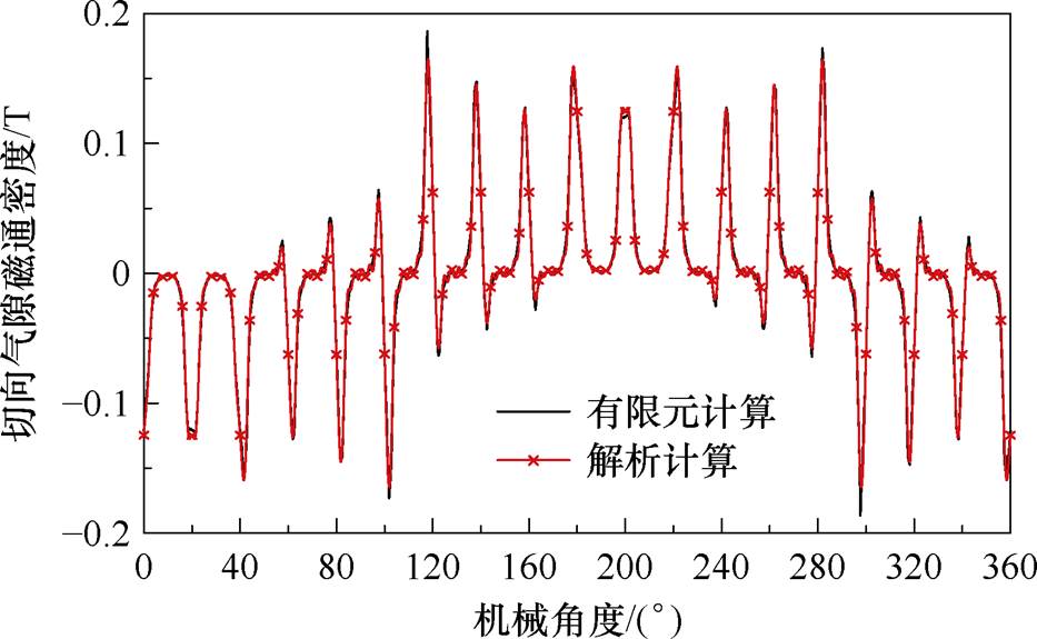
图3 切向气隙磁通密度(s=0, r=Rd)
Fig.3 Tangential airgap flux density (s=0, r=Rd)
从图2、图3可以看出,径向和切向气隙磁通密度波形解析计算与有限元计算结果高度重合。同步运行时电机没有产生机电能量转换,因此转子磁力线不会产生“扭转”现象,如图4所示,解析法得到转子磁力线与有限元仿真一致。图4b局部放大了磁力线从铜层到铁心发生的折射现象,这是由于铜层和转子铁心磁导率不同导致的。
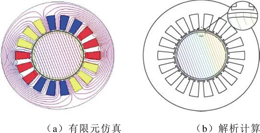
图4 电机磁力线分布(s=0)
Fig.4 Magnetic field lines distribution at s=0
(2)当转差率s=0.05时,径向和切向气隙磁通密度如图5、图6所示,解析计算结果与有限元计算高度一致。转子磁力线相比同步运行时发生了“扭转”,如图7所示。转子在q=p处涡流分布如图8所示,涡流主要集中在转子铜层内。
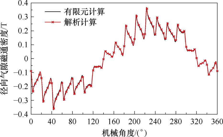
图5 径向气隙磁通密度(s=0.05, r=Rd)
Fig.5 Radial airgap flux density (s=0.05, r=Rd)
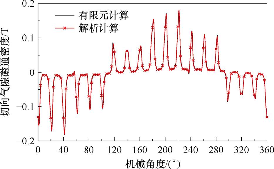
图6 切向气隙磁通密度(s=0.05, r=Rd)
Fig.6 Tangential airgap flux density (s=0.05, r=Rd)
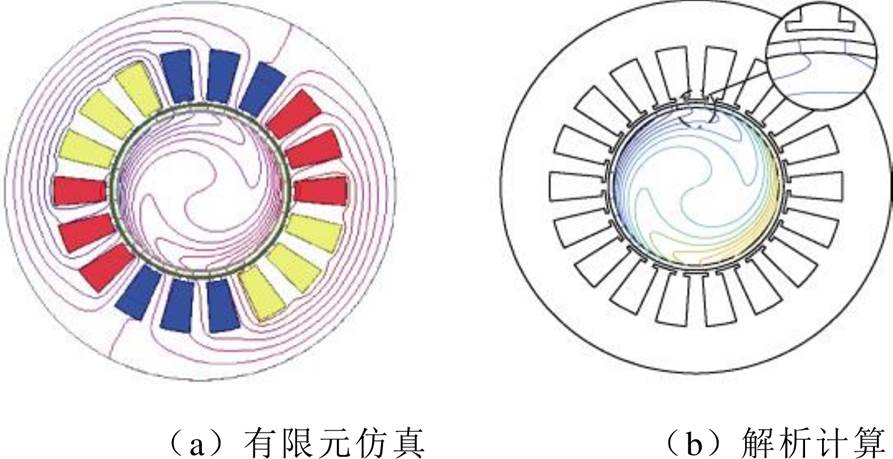
图7 电机磁力线分布对比(s=0.05)
Fig.7 Magnetic field lines distribution at s=0.05
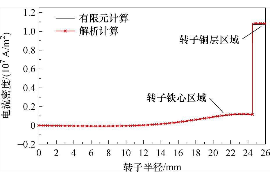
图8 转子内涡流密度(q=p, s=0.05)
Fig.8 Eddy current density in rotor (q=p, s=0.05)
(3)当转差率s=1时,堵转状态下电机气隙磁场储能减小,转子涡流损耗增大,因此气隙磁通密度显著减小,转子涡流增大。径向和切向气隙磁通密度如图9、图10所示,解析计算结果与有限元计算同样高度一致。转子趋肤效应明显,磁场透入深度显著减小,如图11所示。转子在q=π处涡流密度分布如图12所示,涡流的趋肤效应比s=0.05时更加明显。
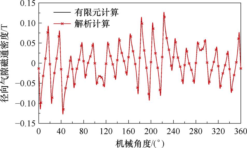
图9 径向气隙磁通密度(s=1, r=Rd)
Fig.9 Radial airgap flux density (s=1, r=Rd)
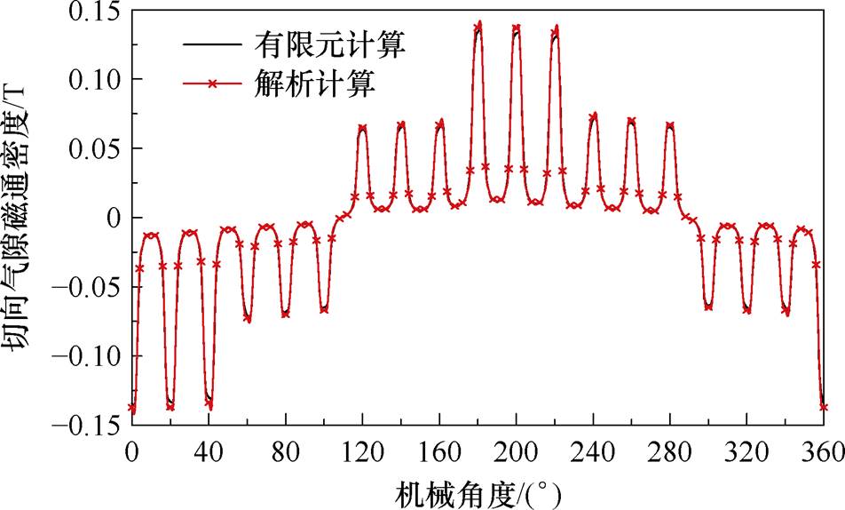
图10 切向气隙磁通密度(s=1, r=Rd)
Fig.10 Tangential airgap flux density (s=1, r=Rd)
求得气隙径向和切向磁通密度便可通过麦克斯韦应力张量法对电磁转矩Te进行计算,有
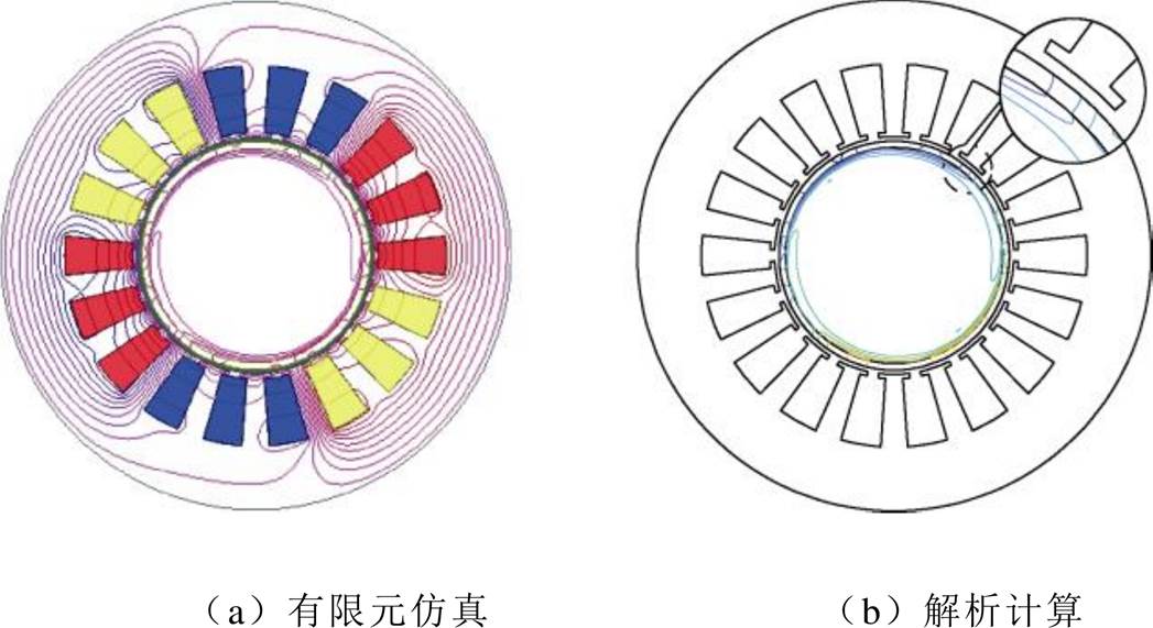
图11 电机磁力线分布对比(s=1)
Fig.11 Magnetic field lines distribution at s=1
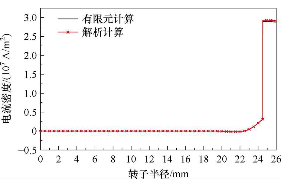
图12 转子内涡流密度(q=π, s=1)
Fig.12 Eddy current density in rotor (q=π, s=1)
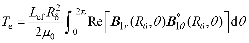 (63)
(63)
式中, 为
为 的共轭复数。将式(61)和式(62)代入式(63)可得
 (64)
(64)
其中
 (65)
(65)
在恒定相电流(幅值为Imax)输入下,电磁转矩随转差率变化曲线如图13所示。在电流源输入下采用麦克斯韦应力张量法能够对电磁转矩准确计算。
图13 麦克斯韦应力张量法计算电磁转矩随转差率变化(相电流幅值Imax)
Fig.13 Electromagnetic torque versus slip calculation via Maxwell stress tensor method (phase current amplitude Imax)
本文提出解析方法由于涉及傅里叶级数与高阶贝塞尔函数计算,过高的谐波阶次虽然能够提高计算精度,但会造成计算时间增加。谐波次数n、m、k的取值对计算时间的影响见表2。不同谐波次数对应的空载气隙磁通密度波形如图14所示。从表2和图14可以看出,当n、m、k从40、2、2提高到80、3、3时,气隙磁通密度已经与有限元计算结果比较接近了,相应的计算时间从6 s增加到30 s,继续提高谐波次数到120、5、5时,计算精度提高已不明显,计算时间增加到了83 s。采用有限元计算时间为199 s(网格数:284 478,处理器:Inter R Xeon R CPU E4-2640,内存:128 G)。因此,选择合适的谐波次数,在保证计算精度的同时,相比有限元计算能够加快计算速度。
表2 解析法与有限元计算时间
Tab.2 Analytical method and finite element computation time
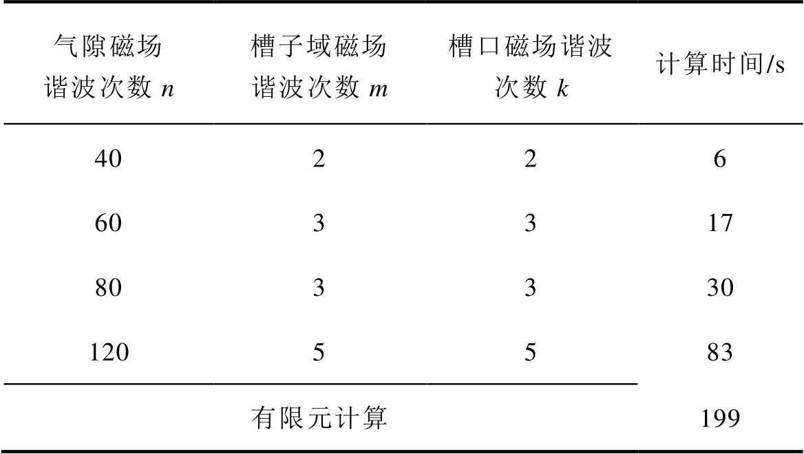
气隙磁场谐波次数n槽子域磁场谐波次数m槽口磁场谐波次数k计算时间/s 40226 603317 803330 1205583 有限元计算199
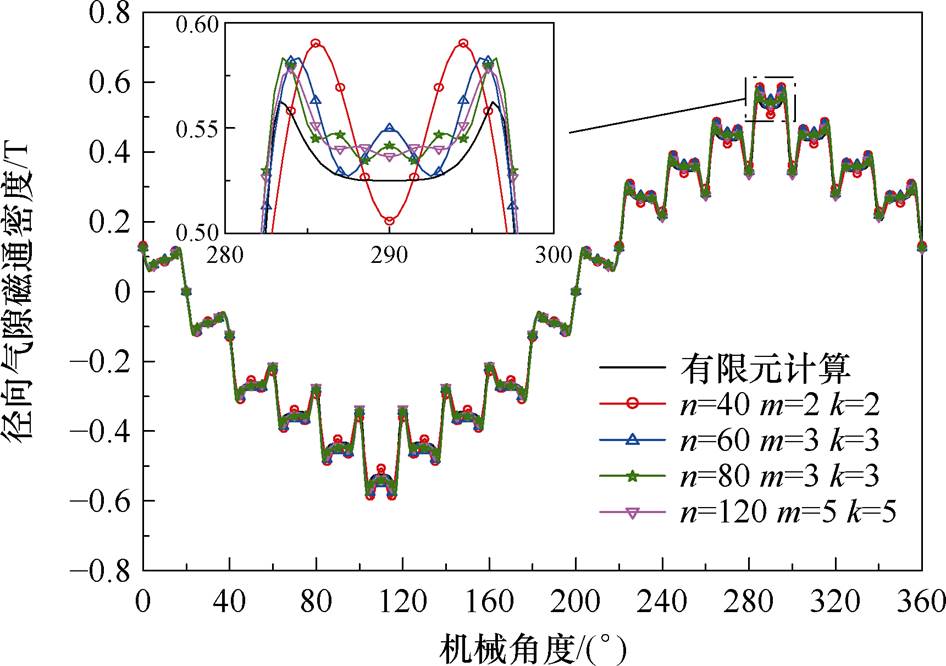
图14 不同谐波次数下的空载径向磁通密度
Fig.14 No-load radial magnetic flux density under different harmonic orders
等效电路是快速计算感应电机性能的重要工具。实心转子感应电机由于等效电路参数计算的方式不同,等效电路的形式也不相同。常用的阻抗计算方法为波阻抗法[4-5],忽略了谐波磁场的影响。本文子域解析法对考虑谐波的电磁场积分,得到励磁电抗及转子阻抗。本节对比了波阻抗法及子域解析法计算等效电路参数。
波阻抗法一般采用忽略定子开槽模型[5, 7],如图15所示。定子绕组等效为定子内表面电流层,电流面密度可表示为Jc=3KwNImaxejp(q-p/9)/(pR2)。其中,N为每相串联匝数,Kw为绕组系数。
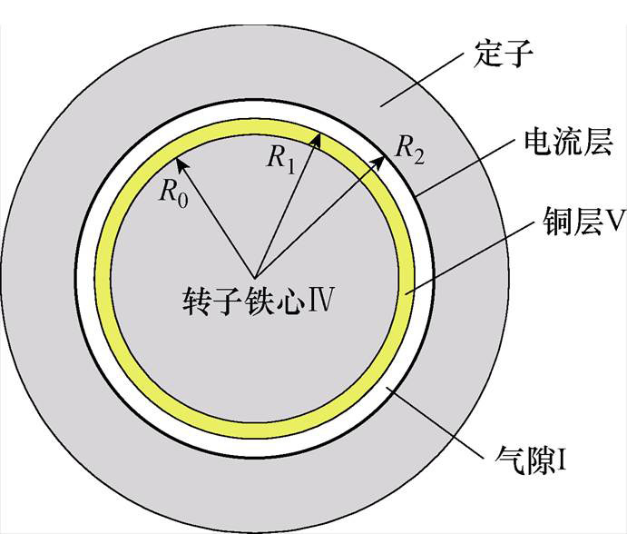
图15 忽略定子开槽覆铜实心转子感应电机波阻抗模型
Fig.15 Wave impedance model of a copper-coated solid rotor induction motor with stator slotting effects neglected
图16为波阻抗法计算阻抗参数时的等效电路,与传统等效电路不同,励磁电抗分为Xm1和Xm2两部分,Xm1为只包含主磁路定子齿、定子轭、气隙三部分的励磁电抗。Xm2为主磁路在转子上磁压降对应的励磁电抗,且包含在波阻抗法转子阻抗 中。
中。 和
和 分别为转子电阻和电抗,
 、
、 分别为定子相电流、转子相电流,U1为输入相电压。
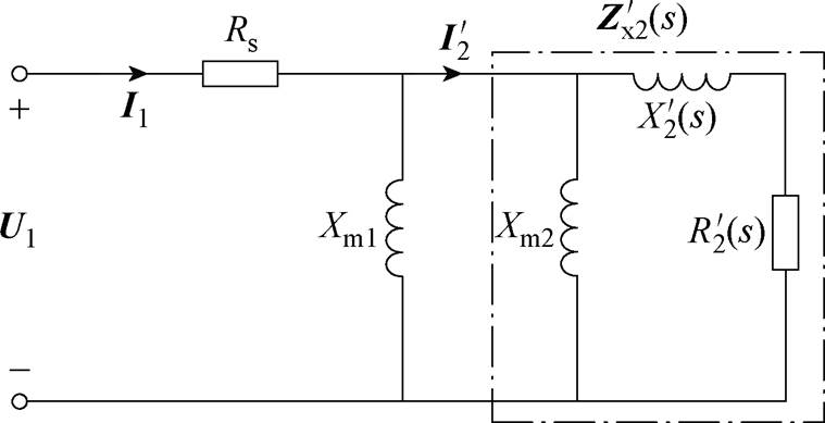
图16 覆铜实心转子感应电机等效电路(波阻抗法)
Fig.16 Equivalent circuit of copper-coated solid rotor induction motors (method of wave impedance)
1)励磁电抗Xm1求解
在定子齿、定子轭和气隙中磁压降对应励磁电抗Xm1由传统电机设计的磁路法计算[24]为
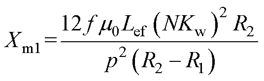 (66)
(66)
由式(66)得励磁电抗Xm1=68.38 W。
2)转子阻抗求解
单位长度转子阻抗Zp可由转子表面波阻抗公式表示[4, 7],有
 (67)
(67)
式中,EⅤ,z(R1, q)为铜层表面轴向电场强度;HⅤ,q(R1,q)为铜层表面切向磁场强度。
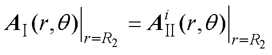
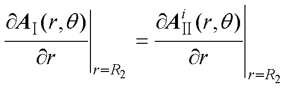
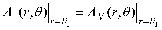
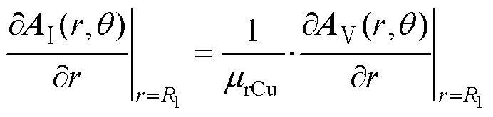
气隙、转子铁心和铜层的矢量磁位AⅠ、AⅣ和AⅤ的通解参考式(6)、式(23)、式(24)、式(29)、式(30),令气隙谐波次数n=1。
气隙与定子边界条件为
 (68)
(68)
气隙与铜层,铜层与转子铁心边界条件与式(34)、式(35)、式(38)和式(39)相同。根据边界条件即可得到铜层矢量磁位AⅤ,由式(2)和式(3)得到EⅤ, z(R1, q)和HⅤ, q(R1, q)。
归算到定子侧的转子总阻抗值 为
为
 (69)
(69)
当输入三相电压源U1=Um[1 e-j2p/3 e-j2p/3]时,由等效电路可得,定子相电流I1为
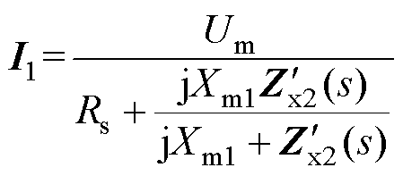 (70)
(70)
转子侧电磁功率Pem为
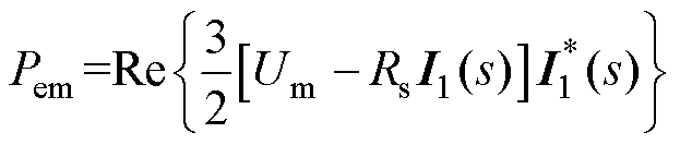 (71)
(71)
式中, 为
为 的共轭复数。
电磁转矩为
 (72)
(72)
图17为子域解析法等效电路,与波阻抗等效电路不同,子域法励磁电抗Xm为整个磁路的励磁电抗,子域解析法转子阻抗 不包括主磁路励磁电抗,且子域解析法从电磁场量积分的角度对阻抗参数计算,与有限元法原理相似。
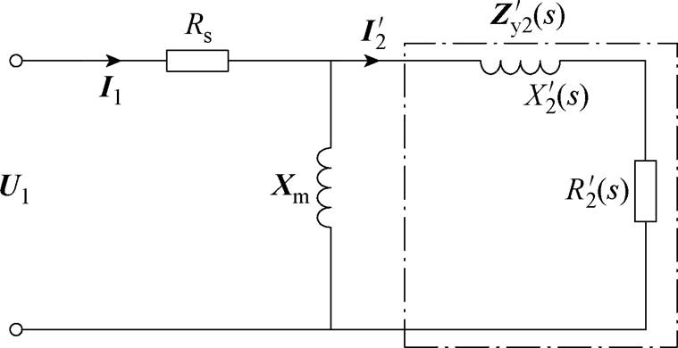
图17 覆铜实心转子感应电机等效电路(子域解析法)
Fig.17 Equivalent circuit of copper-coated solid rotor induction motors (subdomain analytical method)
1)励磁电抗Xm求解
当电机同步运行时(s=0),等效电路转子侧等效为开路,励磁电抗Xm可由给定定子电流Imax和产生的相绕组磁链 求得,有
求得,有
 (73)
(73)
ABC相磁链、 和
和 为
为
 (74)
(74)
 (75)
(75)
由式(73)~式(75)得励磁电抗Xm=25.78j W。
2)子域解析法转子阻抗求解
当电机异步运行时(s≠0),转子阻抗可由给定转差率下的相绕组磁链 及等效电路间接求取。为便于求解,绕组输入幅值为Imax的电流源。转子电流为
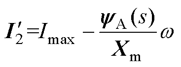 (76)
(76)
子域解析法转子阻抗为
 (77)
(77)
在电压源输入下,由图17等效电路可得定子相电流I1为
 (78)
(78)
转子侧电磁功率、电磁转矩计算公式与式(71)、式(72)相同。
由于波阻抗法与子域解析法等效电路对励磁电抗和转子阻抗定义不同,因此比较阻抗参数计算精度只能从等效电路定子侧输入阻抗角度对比。波阻抗法输入阻抗Zinx与子域解析法输入阻抗Ziny分别为
 (79)
(79)
 (80)
(80)
由式(79)、式(80)得到输入阻抗的电阻和电抗随转差率变化曲线如图18、图19所示。输入电阻采用子域解析法、波阻抗法计算与有限元计算结果接近;输入电抗采用子域解析法与有限元计算结果一致性较高,而波阻抗法相比有限元法计算误差随着转差率增大而增大。
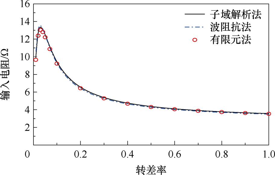
图18 输入电阻随转差率变化
Fig.18 Input resistance varies with the slip
为分析波阻抗法计算输入电抗误差产生的原因,将空载与负载(s=0.01, 0.05)时的径向气隙磁通密度进行对比,如图20~图22所示。空载时波阻抗计算的气隙磁通密度幅值与相位接近子域解析法和有限元法,如图20所示;随着转差率增大,波阻抗计算磁通密度幅值虽然与另两种方法接近,但相位误差逐渐增大,如图21和图22所示,这是由于波阻抗法只能考虑基波磁场,空载时谐波磁场较小,随着转差率增大,谐波磁场的影响增大,造成波阻抗法磁通密度波形相位误差增大。因此,波阻抗法只有在低转差率下才具备较高精度,而本文子域解析法计算精度不受转差率变化影响。
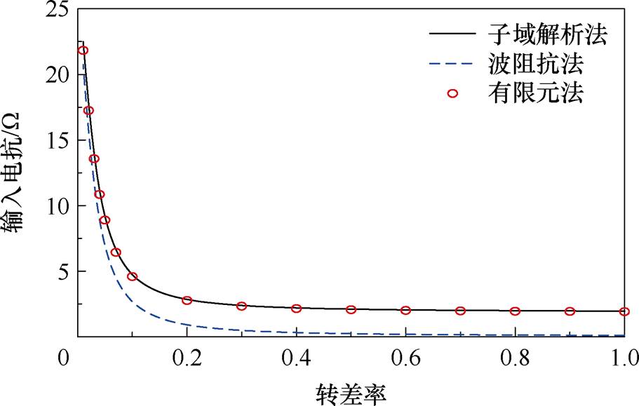
图19 输入电抗随转差率变化
Fig.19 Input reactance varies with the slip
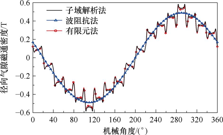
图20 空载径向气隙磁通密度
Fig.20 No-load radial air-gap magnetic flux density
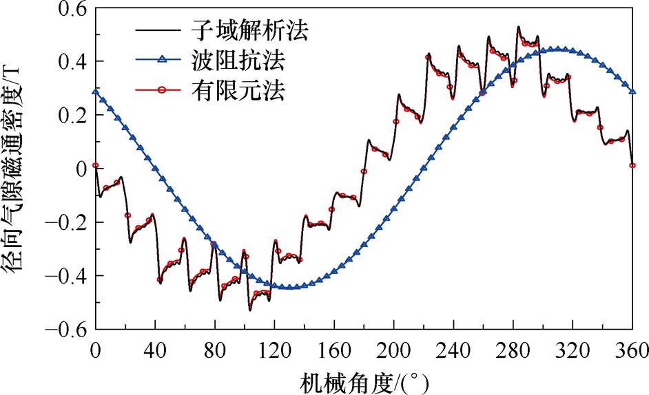
图21 负载(s=0.01)径向气隙磁通密度
Fig.21 Radial air-gap magnetic flux density (s=0.01)
三种方法计算定子电流幅值、电磁转矩在电压源输入时随转差率变化如图23和图24所示,波阻抗法只有在小转差率时误差较小,这与波阻抗法计算输入阻抗只有在小转差率下才具备较高准确性对应,而本文子域解析法计算定子电流和电磁转矩与有限元结果一致性较高,且不受转差率变化影响。
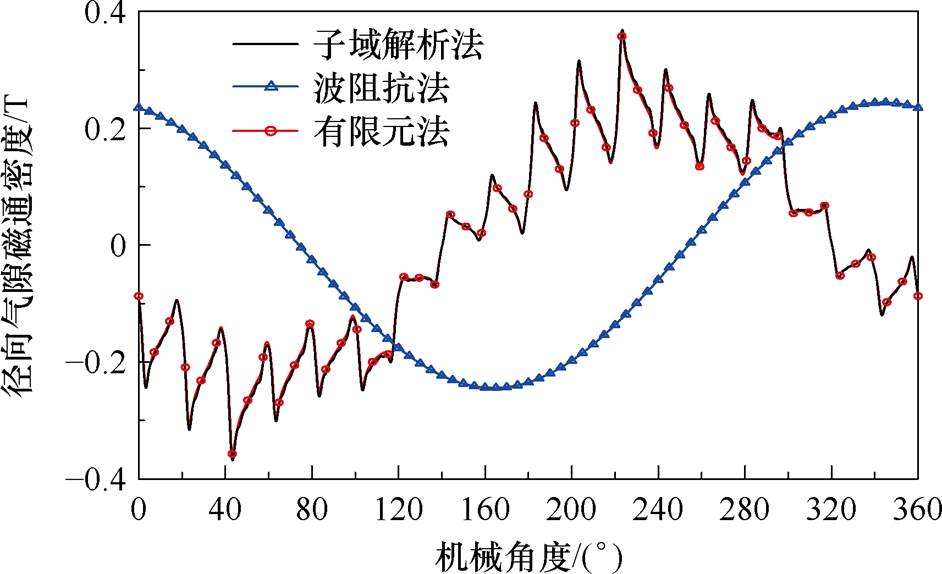
图22 负载(s=0.05)径向气隙磁通密度
Fig.22 Radial air-gap magnetic flux density (s=0.05)
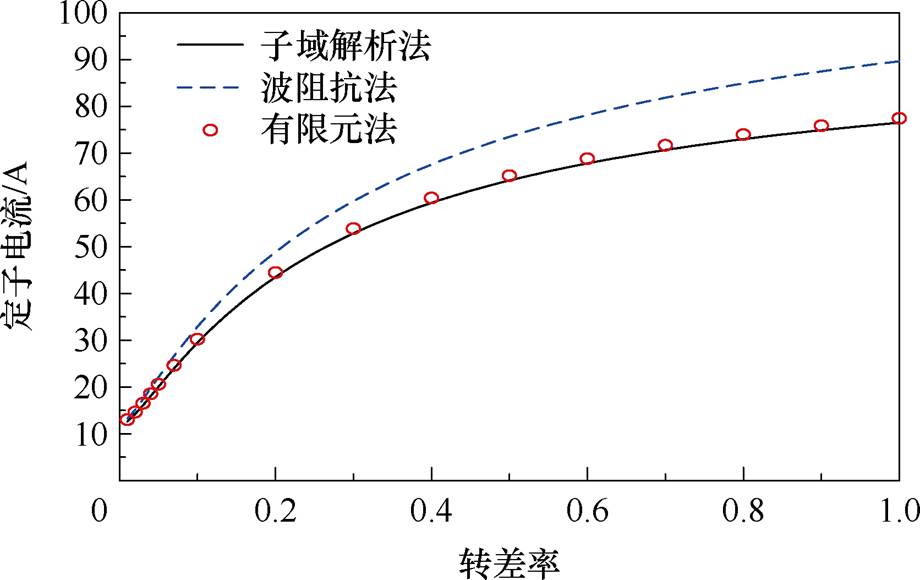
图23 定子电流随转差率变化
Fig.23 Stator current varies with the slip
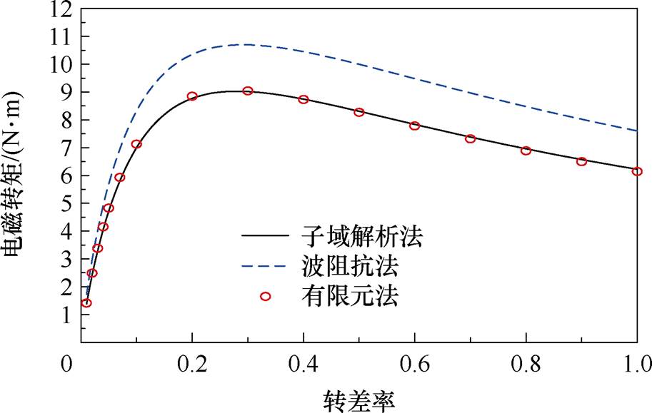
图24 电压源输入下电磁转矩随转差率变化
Fig.24 Electromagnetic torque versus slip under voltage source input
本文建立了覆铜实心转子感应电机考虑定子开槽的二维子域解析模型。将气隙子域、槽子域、槽口子域、铜层子域、转子铁心子域的矢量磁位通过有限阶次的傅里叶级数表示。用解析法清晰呈现了同步和异步工况下的气隙磁场、转子内磁力线分布、转子内涡流分布,并采用二维涡流场有限元验证了子域解析法计算电机内电磁场的准确性。对比了不同谐波阶次对计算时间和准确性的影响,证明了选择适当的谐波阶次能够在保持解析法快速性的同时,获得与有限元法相当的计算精度。
本文对比了子域解析法与常用的波阻抗法实心转子感应电机等效电路的差异,计算了等效电路输入阻抗参数、定子电流和电磁转矩,波阻抗法由于不能考虑电磁场谐波,只有在小转差率时计算误差较小,而子域解析法能够精确计算谐波电磁场,因此计算精度不受转差率变化的影响。
附 录
为便于求解谐波系数,先定义如下函数。
 (A1)
(A1)
 (A2)
(A2)
 (A3)
(A3)
 (A4)
(A4)
 (A5)
(A5)
将式(9)代入式(40)和式(41)得
 (A6)
(A6)
 (A7)
(A7)
将式(13)代入式(42)和式(43)得
 (A8)
(A8)
 (A9)
(A9)
将式(9)代入式(44)和式(45)得
 (A10)
(A10)
 (A11)
(A11)
将式(29)、式(30)代入式(46)和式(47)得
 (A12)
(A12)
 (A13)
(A13)
 (A14)
(A14)
 (A15)
(A15)
式(A12)、式(A14)为异步运行谐波系数方程,式(A13)、式(A15)为同步运行谐波系数方程。
将式(18)代入式(48)和式(49)得
 (A16)
(A16)
 (A17)
(A17)
将式(13)代入式(50)和式(51)得
 (A18)
(A18)
 (A19)
(A19)
将式(29)、式(30)代入式(52)和式(53)得
 (A20)
(A20)
 (A21)
(A21)
 (A22)
(A22)
 (A23)
(A23)
式(A20)、式(A22)为异步运行谐波系数方程,式(A21)、式(A23)为同步运行谐波系数方程。
将式(23)、式(24)代入式(54)~式(57)得
 (A24)
(A24)
 (A25)
(A25)
 (A26)
(A26)
 (A27)
(A27)
式(A24)、式(A26)为异步运行谐波系数方程,式(A25)、式(A27)为同步运行谐波系数方程。
将傅里叶级数阶次从无穷大改变有限值,即n、m、k取有限值,则式(A6)~式(A27)线性方程组可写成有限阶次的矩阵的形式,通过Matalb编程即可得到谐波系数A1n、A2n、A3n、A4n、 、
、 、
、 、
、 、
、 、
、 、D1n、D2n、G1n、G2n、G3n、G4n。
参考文献
[1] 陈鑫杰, 王慧贞. 航空电源系统用高速实心式永磁同步电机设计[J]. 电机与控制应用, 2024, 51(2): 61-70.
Chen Xinjie, Wang Huizhen. Design of high-speed solid permanent magnet synchronous motor for aviation power system[J]. Electric Machines & Control Application, 2024, 51(2): 61-70.
[2] 唐孝镐, 宁玉泉, 傅丰礼. 实心转子异步电机及其应用[M]. 北京: 机械工业出版社, 1991.
[3] Gerada D, Mebarki A, Brown N L, et al. High-speed electrical machines: technologies, trends, and developments[J]. IEEE Transactions on Industrial Electronics, 2014, 61(6): 2946-2959.
[4] Gieras J F, Saari J. Performance calculation for a high-speed solid-rotor induction motor[J]. IEEE Transactions on Industrial Electronics, 2012, 59(6): 2689-2700.
[5] 黄子果, 王善铭, 倪守辉. 光滑实心转子异步电机等效电路参数的二维计算方法[J]. 中国电机工程学报, 2016, 36(9): 2505-2512.
Huang Ziguo, Wang Shanming, Ni Shouhui. 2D calculation methods of equivalent-circuit parameters in smooth solid rotor induction machines[J]. Pro- ceedings of the CSEE, 2016, 36(9): 2505-2512.
[6] 洪岑岑, 张驰, 滕福林, 等. 自轴承式双定子实心转子盘式异步飞轮电机设计[J]. 微电机, 2021, 54(8): 33-37.
Hong Cencen, Zhang Chi, Teng Fulin, et al. The design of a novel self-bearing dual stator solid rotor axial flux induction motor[J]. Micromotors, 2021, 54(8): 33-37.
[7] 朱利伟, 邓智泉. 考虑材料非线性覆铜实心转子感应电机转子阻抗参数的二维解析计算[J]. 电工技术学报, 2024, 39(24): 7688-7699.
Zhu Liwei, Deng Zhiquan. 2D analytic calculation of rotor-impedance parameters in copper-coated solid rotor induction motors considering the nonlinear material[J]. Transactions of China Electrotechnical Society, 2024, 39(24): 7688-7699.
[8] 黄子果, 王善铭, 孙宇光, 等. 开槽实心转子电机的等效电路参数计算与性能分析[J]. 中国电机工程学报, 2017, 37(4): 1208-1216.
Huang Ziguo, Wang Shanming, Sun Yuguang, et al. Equivalent-circuit parameter calculations and perfor- mance analysis of slit solid rotor asynchronous machines[J]. Proceedings of the CSEE, 2017, 37(4): 1208-1216.
[9] Feng Haichao, Cui Xu, Si Jikai, et al. Equivalent circuit model of novel solid rotor induction motor with toroidal winding applying composite multilayer theory[J]. Applied Sciences, 2019, 9(16): 3288.
[10] Greig J, Freeman E M. Travelling-wave problem in electrical machines[J]. Proceedings of the Institution of Electrical Engineers, 1967, 114(11): 1681.
[11] Pyrhonen J. Calculating the effects of solid-rotor material on high-speed induction motor characteri- stics[J]. European Transactions on Electrical Power, 1991, 1(6): 301-310.
[12] 凌在汛, 周理兵, 张毅, 等. 笼型实心转子屏蔽感应电机电磁场及参数研究(二): 二维多层电磁场模型及其解析计算[J]. 电工技术学报, 2018, 33(17): 4016-4028.
Ling Zaixun, Zhou Libing, Zhang Yi, et al. Parameters determination and electromagnetic field analysis of canned solid-rotor induction motor(2): 2D-multilayer electromagnetic model and its analytical calculation[J]. Transactions of China Electrotechnical Society, 2018, 33(17): 4016-4028.
[13] Räisänen V, Suuriniemi S, Kurz S, et al. Rapid computation of harmonic eddy-current losses in high-speed solid-rotor induction machines[J]. IEEE Transactions on Energy Conversion, 2013, 28(3): 782-790.
[14] 李世奇, 佟文明, 贾建国, 等. 考虑磁桥非线性的内置式永磁同步电机空载电磁性能通用解析模型[J]. 电工技术学报, 2023, 38(6): 1421-1432.
Li Shiqi, Tong Wenming, Jia Jianguo, et al. General analytical model of No-load electromagnetic perfor- mance of interior permanent magnet synchronous motors considering nonlinearity of magnetic bridges[J]. Transactions of China Electrotechnical Society, 2023, 38(6): 1421-1432.
[15] 佟文明, 杜绍雨, 贾建国, 等. 基于改进复相对磁导函数的开槽轴向磁通永磁电机气隙磁场解析模型[J]. 电工技术学报, 2024, 39(24): 7700-7711.
Tong Wenming, Du Shaoyu, Jia Jianguo, et al. Analytical model of air-gap magnetic field of slotted axial flux permanent magnet motor based on improved complex relative permeance function[J]. Transactions of China Electrotechnical Society, 2024, 39(24): 7700-7711.
[16] 佟文明, 杨先凯, 鹿吉文, 等. 双层永磁体结构高速永磁电机转子涡流损耗解析模型[J]. 电工技术学报, 2024, 39(20): 6293-6304.
Tong Wenming, Yang Xiankai, Lu Jiwen, et al. Rotor eddy current loss analytical model for high-speed permanent magnet motor based on double layer permanent magnet structure[J]. Transactions of China Electrotechnical Society, 2024, 39(20): 6293-6304.
[17] 佟文明, 田野, 李晓健, 等. 双层复合护套高速永磁电机转子涡流损耗解析模型[J]. 电工技术学报, 2024, 39(14): 4328-4340.
Tong Wenming, Tian Ye, Li Xiaojian, et al. Analytical modeling for rotor eddy current loss of high-speed surface-mounted permanent magnet motor with double-layer compound retaining sleeve[J]. Transactions of China Electrotechnical Society, 2024, 39(14): 4328-4340.
[18] 于博学, 刘光伟, 宋志环, 等. 内置式双V型断桥结构永磁同步电机空载电磁性能解析计算[J]. 电机与控制学报, 2025, 29(5): 31-40.
Yu Boxue, Liu Guangwei, Song Zhihuan, et al. Analytical calculation of no-load electromagnetic performance for interior permanent magnet syn- chronous motor with double-V magnetic bridge break shape[J]. Electric Machines and Control, 2025, 29(5): 31-40.
[19] Mirzaei M. Computational modeling of an axial airgap induction motor with a solid rotor[J]. IEEE Transactions on Magnetics, 2022, 58(6): 8105109.
[20] 张守首, 郭思源. 基于子域分析模型的实心转子感应电机磁场解析[J]. 电工技术学报, 2021, 36(20): 4285-4296.
Zhang Shoushou, Guo Siyuan. Analytical solution of magnetic field in solid rotor induction machine based on subdomain model[J]. Transactions of China Elec- trotechnical Society, 2021, 36(20): 4285-4296.
[21] Boughrara K, Dubas F, Ibtiouen R. 2-D analytical prediction of eddy currents, circuit model parameters, and steady-state performances in solid rotor induction motors[J]. IEEE Transactions on Magnetics, 2014, 50(12): 7028214.
[22] 许浩, 赵镜红, 熊义勇, 等. 五相实心转子感应电机磁场及参数计算[J]. 华中科技大学学报(自然科学版), 2025, 53(1): 28-34.
Xu Hao, Zhao Jinghong, Xiong Yiyong, et al. Calculation of magnetic field and parameters of five phase solid rotor induction motor[J]. Journal of Huazhong University of Science and Technology (Natural Science Edition), 2025, 53(1): 28-34.
[23] Lubin T, Mezani S, Rezzoug A. Analytical com- putation of the magnetic field distribution in a magnetic gear[J]. IEEE Transactions on Magnetics, 2010, 46(7): 2611-2621.
[24] 陈世坤. 电机设计[M]. 2版. 北京: 机械工业出版社, 1990.
Abstract The rotor magnetic field distribution in copper-coated solid rotor induction motors is complex, making it difficult to visualize the internal field distribution using traditional lumped-parameter magnetic circuit analysis or to account for the influence of slip on equivalent circuit parameters. This paper focuses on solving the electromagnetic field within the copper-coated solid rotor. A subdomain analytical method in cylindrical coordinates is employed for the effects of stator slotting and slot-opening shape on the electromagnetic field. The analytical solutions for the air gap, rotor copper layer, and rotor steel are derived using 2D eddy-current finite-element analysis. Compared with the finite element method, the proposed analytical approach significantly reduces computation time by selecting appropriate harmonic orders. For the copper-coated solid-rotor induction motor, the subdomain analytical method and the traditional wave impedance method are compared with respect to equivalent circuit models, input impedance parameters, and output characteristics. The results demonstrate that the subdomain analytical method achieves greater consistency with finite element calculations across different slip conditions than the traditional wave impedance method.
This paper lists the Laplace equations (for the air-gap and slot-opening subdomains), the Poisson equation (for the slot subdomain), and the Helmholtz equations (for the rotor copper layer and iron core subdomains). The general solutions for the vector magnetic potential in each subdomain are obtained. The harmonic coefficients in the Fourier series of the vector magnetic potential are determined through eight boundary conditions applied at four interfaces. Taking a 2-pole 18-slot copper-coated solid rotor induction motor as the model, the radial and tangential air-gap flux densities, rotor magnetic flux line distributions, and rotor eddy current density distributions under no-load, load, and locked-rotor conditions are calculated. The Maxwell stress torque under current source excitation is derived. The analytical results are validated using a two-dimensional eddy-current field finite-element analysis.
To investigate the influence of harmonic orders on computation time and numerical errors, the harmonic orders for the air gap, slot, and slot opening are incrementally increased, and the resulting discrepancies between analytical results and finite element simulations are observed.
A comparison is made with the traditional wave impedance method regarding the form of the equivalent circuit and the approach to calculating impedance parameters. The reasons for errors in the equivalent circuit parameters computed by the wave impedance method and the subdomain analytical method are compared.
The following conclusions are drawn. (1) The subdomain analytical method can clearly and accurately represent the electromagnetic field distribution in copper-clad solid rotor induction motors. Selecting appropriate harmonic orders maintains computational efficiency while achieving accuracy. (2) Compared to the wave impedance method, the proposed subdomain analytical method provides more accurate calculations of equivalent circuit parameters and remains unaffected by variations in slip.
keywords:Copper-coated solid rotor induction motors, subdomain analytical method, electromagnetic field distribution, wave impedance method, equivalent circuit
DOI: 10.19595/j.cnki.1000-6753.tces.250431
中图分类号:TM346
国家自然科学基金资助项目(52177049)。
收稿日期 2025-03-18
改稿日期 2025-07-18
朱利伟 男,1991年生,博士研究生,研究方向为高速实心转子感应电机设计及优化。E-mail: liweizhu@nuaa.edu.cn
邓智泉 男,1969年生,教授,博士生导师,研究方向为高速电机技术、磁轴承技术、无轴承电机等。E-mail: dzq@nuaa.edu.cn(通信作者)
(编辑 崔文静)