 (1)
(1)
摘要 高比例电力电子化已成为新型电力系统的典型特征,新能源并网系统的小干扰稳定性问题日益凸显。由于生产工艺、元件老化和线路参数测量存在误差等原因,实际系统中的元件参数与标称值之间会存在一定偏差,但目前尚缺乏一种可计及参数不确定性的多变流器并网系统鲁棒稳定性的系统性分析方法。首先,该文基于线性分式变换和谐波线性化建模方法,在分别建立滤波电感和电容、直流电容和电网线路参数不确定性模型的基础上,提出一种可计及并网逆变器系统多参数不确定性的dq坐标系小信号模型。然后,经推导获得不确定系统的MD结构模型及其传递函数表达式,结合m分析理论,实现了一种用于评估并网逆变器系统鲁棒稳定性的分析方法,所获得的结构奇异值(SSV)可作为系统稳定裕度的度量指标。最后,结合典型算例开展了Matlab/Simulink仿真和硬件在环实验,分析结果发现,利用SSV的频率特性曲线亦可获得临界稳定状态下的系统振荡频率,可用于不确定系统鲁棒稳定性分析方法的量化验证。通过对比所提方法与仿真结果,验证了所提方法的正确性。
关键词:并网逆变器 dq小信号模型 参数不确定性 鲁棒稳定性
随着“双碳”战略目标的稳步推进,大力发展以光伏、风电为代表的可再生能源已经成为我国能源转型的必然选择。当前我国电力系统呈现出明显的高比例可再生能源和高比例电力电子设备的“双高”特性[1-3],以电力电子为接口的新能源并网设备(简称“变流器”)显著改变了以同步机为主导的电力系统的特性,系统小干扰稳定性问题成为近年来研究的热点[4-5]。
用于评估电力电子系统小干扰稳定性的确定性分析方法主要有状态空间法[6-7]和阻抗的方法[8-9]。将这类方法称为“确定性方法”是源于其采用标称参数建立系统模型(简称“标称模型”),然后依据经典稳定性判据(特征值或奈奎斯特判据)评估系统的稳定性。然而,由于生产工艺、元件老化、工作环境差异和线路参数存在误差等原因,系统中元件的真实参数与标称参数必然存在一定偏差,这些参数所存在的不确定性会对系统小干扰稳定性造成一定影响[10-11]。由于标称模型忽略了系统参数的不确定性,使得确定性分析方法因无法考虑最恶劣的情况而可能造成分析结果错误[12]。因此,为更为全面准确地评估变流器系统的小信号稳定性,从忽略参数不确定性的确定性方法转变为考虑这些不确定性的替代方法十分必要。
为了计及系统参数不确定性的影响,一种常用的方法是将确定性分析法与蒙特卡洛法相结合,从概率的角度对系统稳定性进行评估[13-16]。然而,这类方法需要根据参数的变化在多个平衡点处逐一进行线性化建模,过程繁琐、工作量大。文献[17]提出了一种基于导纳空间的稳定性分析方法,该方法在应用阻抗法时引入了参数的不确定性,并开发了相应的自动化程序以简化分析过程。虽然这种方法可用于确定关键特征值的概率密度函数,但不能保证识别与稳定性相关的最关键的系统场景[18-19],故而无法实现对系统的稳定裕度的量化评估。自20世纪90年代以来,多变量控制理论的重要发展使得m分析理论更加完善和实用[20-21]。基于结构奇异值(Structure Singular Value, SSV)的m分析已被证明可以在不确定系统的稳定性评估中获得可靠的结 果[22-24]。一方面,相比于蒙特卡洛法,m分析避免了迭代建模所带来的反复的线性化过程,大大降低了工作量;另一方面,对于多输入多输出(Multipe Input Multiple Output, MIMO)系统,相比于特征值仅是在输入和输出方向相同时(即特征向量的方向)提供有关系统增益的信息,奇异值则可提供关于任何输入方向的最大增益信息,因此其是分析MIMO系统更为合适的选择[25-29]。文献[30]建立了线性时不变系统的不确定MD结构模型,并利用SSV评估了计及不确定参数的多发电机系统的鲁棒稳定性。文献[31-32]通过建立计及运行条件不确定性的电力系统分析模型,提出了一种基于m分析的电力系统小干扰稳定性分析方法。但上述文献仅是以传统电力系统为分析对象,并未涉及电力电子变流器设备。
近年来,随着用于分析变流器系统小干扰稳定性的确定性方法研究的逐渐成熟,学者们开始着眼于研究计及参数不确定性变流器系统的鲁棒稳定 性[10-11, 33-41]。文献[10]将状态空间法和m分析相结合,提出了一种用于评估具有单一和多个参数不确定性的DC-DC Buck变换器鲁棒稳定性的实用方法。文献[11]应用m分析评估了含有恒功率负载的变流器系统的鲁棒稳定性,并指明SSV可作为度量不确定系统鲁棒稳定性的有效指标。文献[33]亦采用状态空间法和线性分式变换[25, 34](Linear Fractional Transform, LFT)建立了单相逆变器的小信号模型,并利用m分析研究了计及滤波参数不确定性系统的鲁棒稳定性。采用相同的方法,文献[35]提出了一种三相跟网(Grid-Following, GFL)型并网逆变器的鲁棒稳定性分析模型,分析了因元件公差和老化效应导致的LCL滤波器参数变化对系统稳定性的影响。文献[36]提出了一种基于虚拟同步机(Virtual Synchronous Generator, VSG)控制策略的三相构网(Grid-Forming, GFM)型并网逆变器的鲁棒稳定性分析模型,重点分析了电网强度对系统稳定性的影响。但上述文献仅是针对单个变流器系统,随着研究的不断深入,开展多变流器系统的鲁棒稳定性分析将更具意义。文献[37]同样采用状态空间法结合m分析对同时含有GFL和GFM逆变器的系统进行了建模和鲁棒稳定性分析,讨论了两类变流器间电气距离不确定性对系统稳定性的影响。但基于时域状态空间的建模方法难以应用于含有大量变流器的系统,原因在于其会因数学模型阶数过高而导致“维数灾”问题[38]。相比于在时域进行建模的状态空间法,基于频域的阻抗法由于仅是将变流器描述为一个阻抗模型,所建模型更为简单,更加适合多变流器系统建模。文献[39-40]基于阻抗法建立了用于分析多变流器系统鲁棒稳定性的分析模型,并结合m分析实现了变流器导纳和电网强度存在不确定性的系统稳定性分析。然而,该方法是在变流器的标称输出导纳的基础上引入“宏观”不确定性,而滤波电感和电容参数不确定性在各频率上对输出导纳大小的影响不尽相同,因此这种“宏观”不确定性的描述方式并不准确。而且,由于此类方法中滤波器参数被“隐式”地包含于变流器阻抗表达式中,难以显式地分析滤波器参数不确定性对系统稳定性的影响。文献[41]基于GFL和GFM逆变器动态模型中电压电流存在对偶性的事实,分别对GFL和GFM逆变器的电网阻抗参数和等效负载参数的不确定性进行了建模。但该方法仅适用于分析考虑电网阻抗和负载参数不确定性下的系统的稳定性,而无法考虑变流器滤波参数的不确定性。而且,该方法在建模过程中也未考虑小干扰下因GFL锁相环环节和GFM的P-f控制环节所造成的电气dq坐标系与控制dq坐标系间的相位差异,模型精度有待提升。
综上所述,现有文献在分析变流器系统鲁棒小干扰稳定性时尚存在如下不足:①在分析对象上,现有研究多是侧重于单变流器并网系统或者仅考虑了电网运行参数的不确定性,尚不存在综合考虑变流器参数及电网参数等多参数不确定性下的小干扰稳定性分析模型;②在分析方法上,基于蒙特卡洛的鲁棒稳定性分析方法分析过程繁杂且无法量化稳定裕度。对于基于状态空间结合m分析的鲁棒稳定性分析方法,建立多变流器系统状态方程时容易导致“维数灾”问题,故该方法在用于多变流器系统分析时受到较大限制。对于基于频域阻抗模型结合m分析的鲁棒稳定性分析方法,由于变流器参数的摄动量被隐式的包含于变流器阻抗表达式之中,无法显式地讨论内部参数对于系统稳定性的影响。
针对上述不足,本文将用于电力电子变流器建模的谐波线性化法与LFT相结合,建立了用于分析计及变流器滤波器参数、GFL逆变器直流电容和电网线路参数的多参数不确定性的变流器并网系统的dq小信号模型,推导了MD结构模型的传递函数矩阵,并结合m分析提出了一种变流器并网系统鲁棒小干扰稳定性的分析方法。由于本文方法采用了频域传递函数模型,可避免状态空间法的“维数灾”问题,且该模型可详细刻画系统动态行为(如小扰动下造成的电气dq坐标系与控制dq坐标系间的动态相位差异、频率耦合效应等),保证了模型精度。最后,结合典型算例,通过开展Matlab/Simulink仿真和硬件在环(Hardware-in-the-Loop, HIL)实验验证了本文所提方法的正确性。结果分析表明,经本文方法所得到的SSV-f曲线可获得系统的振荡模态,可用于不确定系统鲁棒稳定性分析方法的量化验证。
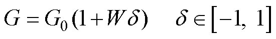
由于生产工艺、元件老化、工作环境差异和线路参数存在误差等原因,系统中元件的真实参数与标称参数将存在一定的偏差,即元件实际参数相对于标称参数存在一定的不确定性。对于某个处在[Gmin, Gmax]区间内有界的参数G,乘性不确定性是一种常用的表示方法[26],通过将参数存在的不确定性归一化为[-1, 1]区间内的有界摄动量d,参数G表示为
(1)
式中, 为参数标称值,
 ;
; 为参数摄动加权系数,
 。
。
LFT作为一种不确定参数的建模手段,其目的是将参数摄动量从标称系统中“拉出”,以构建具有反馈形式的MD结构系统模型。鉴于变流器并网系统中存在两种形式的元件方程,故本部分首先给出两类LFT的通用形式,并据此建立dq坐标系下元件的LFT模型。
1.1.1 第Ⅰ类LFT模型
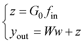
第Ⅰ类LFT模型所适用的输入输出关系为
 (2)
(2)
式中,yout和fin分别为LFT模型的输出和输入。
当计及参数G的不确定性时,相应的LFT模型如图1所示。图1中,w和z为基于LFT将参数摄动量d从系统“拉出”过程中引入的中间变量,分别对应参数摄动量的输入和输出,其具体数学表达式为
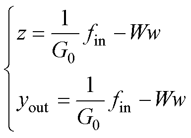 (3)
(3)
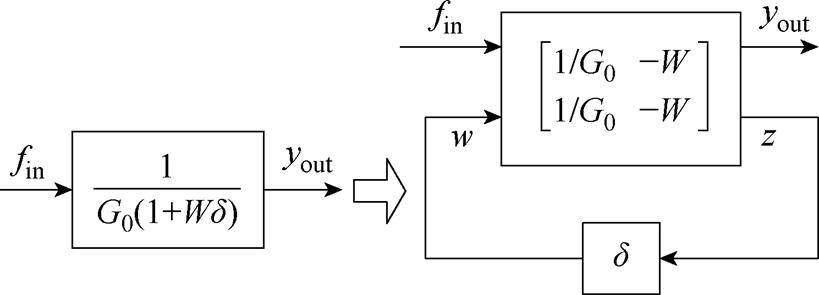
图1 第Ⅰ类LFT模型框图
Fig.1 LFT model diagram of Type I
1.1.2 第Ⅱ类LFT模型
第Ⅱ类LFT模型所适用的输入输出关系为
 (4)
(4)
考虑参数G的不确定性的LFT模型如图2所示。
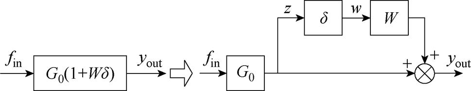
图2 第Ⅱ类LFT模型框图
Fig.2 LFT model diagram of Type II
根据图2,可得第Ⅱ类LFT模型的数学表达式为
 (5)
(5)
1.2.1 dq坐标系下滤波电感L的LFT模型
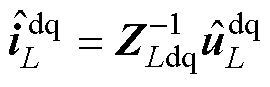
dq坐标系下滤波电感L的伏安关系表达式为
 (6)
(6)
式中, 为滤波电感阻抗矩阵,
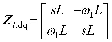 ,w1为工频角频率;
 为滤波电感电压,
 ;
; 为滤波电感电流,
 。对式(6)应用第Ⅰ类LFT模型,则有
 (7)
(7)
其中
根据式(7)可得滤波电感L的LFT模型框图如图3所示。
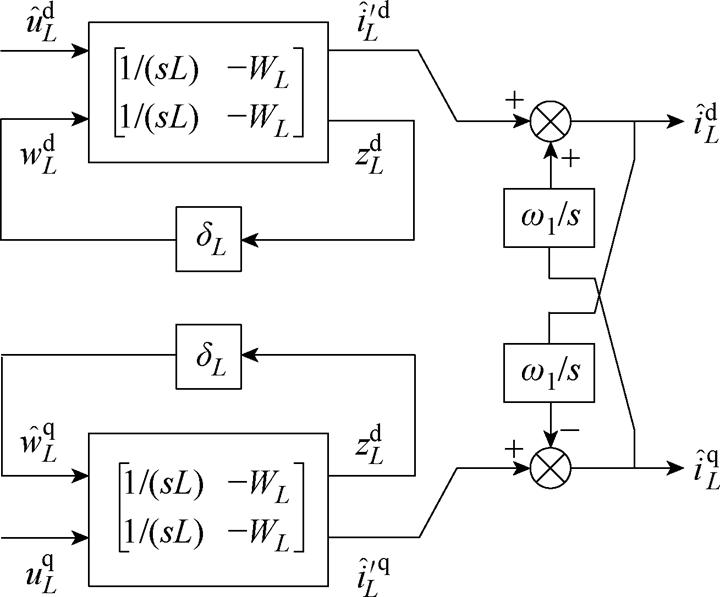
图3 滤波电感L的LFT模型框图
Fig.3 Diagram of LFT model of filter inductance L
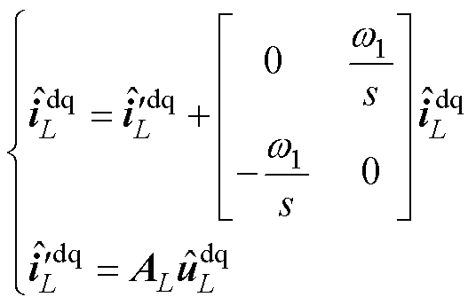
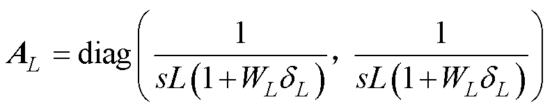
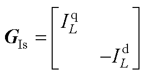
根据图3,可得dq坐标系下滤波电感L的数学表达式为
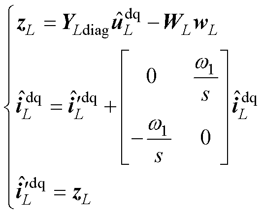 (8)
(8)
其中
1.2.2 dq坐标系下滤波电容C的LFT模型
dq坐标系下滤波电容C的伏安关系表达式为
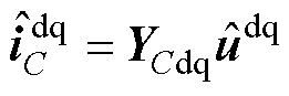 (9)
(9)
式中, 为滤波电容导纳矩阵,
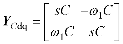 ;
; 为并网点电压,
 ;
; 为滤波电容电流,
 。
。
对式(9)应用第Ⅱ类LFT模型,滤波电容C的LFT模型框图如图4所示。
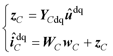
根据图4,可得dq坐标系下滤波电容C的数学表达式为
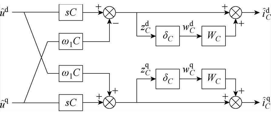
图4 滤波电容C的LFT模型框图
Fig.4 Diagram of LFT model of C
 (10)
(10)
其中
1.2.3 GFL逆变器直流电容Cdc的LFT模型
GFL逆变器直流电容Cdc的伏安关系表达式为
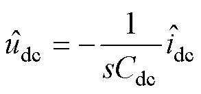 (11)
(11)
式中, 为直流母线电压的小信号扰动量;
 为直流母线电流的小信号扰动量。
对式(11)应用第Ⅰ类LFT模型,可得直流电容Cdc的LFT模型框图如图5所示。
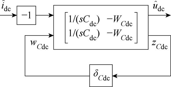
图5 GFL逆变器直流电容Cdc的LFT模型框图
Fig.5 Diagram of LFT model of DC-link capacitance Cdc in GFL inverter
根据图5,可得GFL逆变器直流电容Cdc的数学表达式为
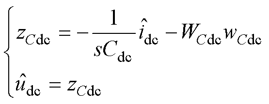 (12)
(12)
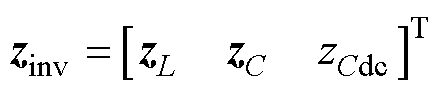
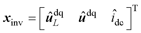
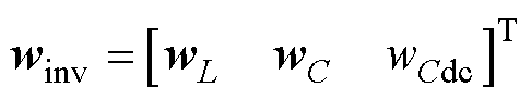
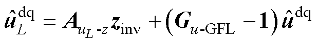
综合式(8)、式(10)和式(12)三式中的第一式,将其写成矩阵形式为
 (13)
(13)
其中
1.2.4 电力网络线路参数的LFT模型
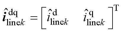
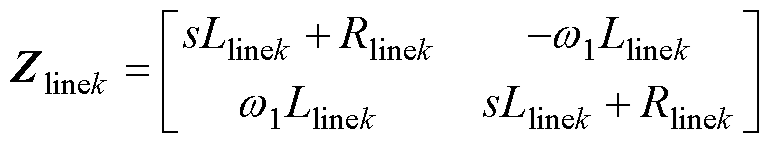
以第k条线路为例,其两端电压和流过其电流的关系为
 (14)
(14)
其中
对式(14)应用第Ⅱ类LFT模型,所得LFT模型框图如图6所示。
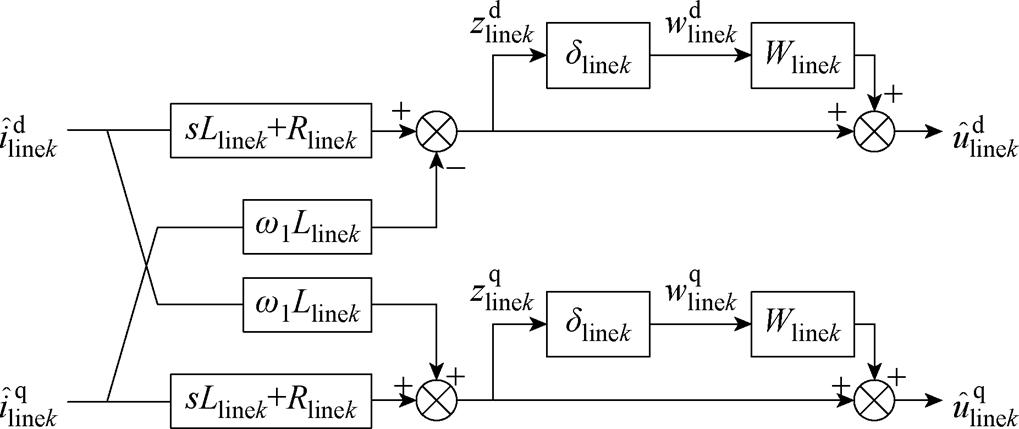
图6 线路电感Llinek的LFT模型框图
Fig.6 Diagram of LFT model of line inductance Llinek
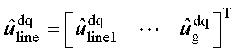
对于由N条线路构成的电力网络,可得其表达式为
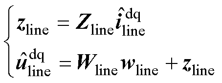 (15)
(15)
其中
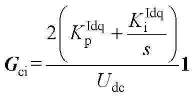
1.3.1 GFL和GFM逆变器的dq频域小信号模型
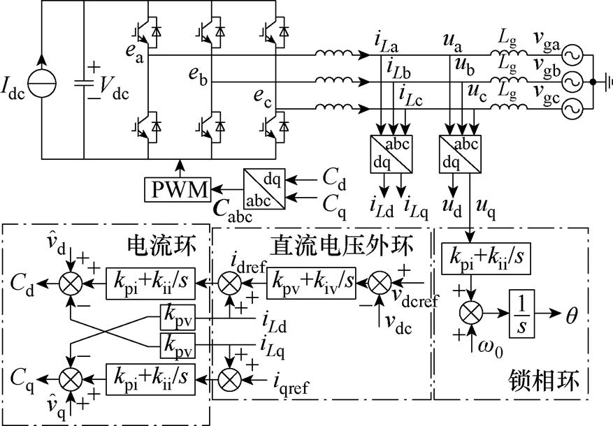
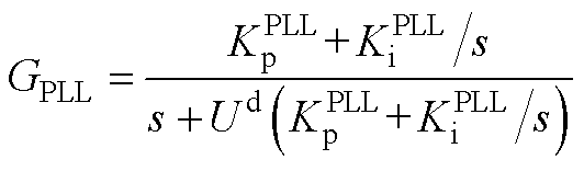
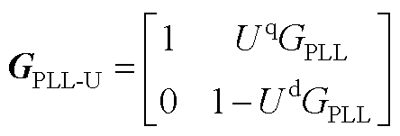
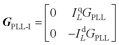
基于谐波线性化法[7-8],下面给出GFL和GFM逆变器的频域小信号模型。GFL变流器的拓扑结构如附图1所示,其小扰动稳定性受锁相环(Phase Lock Looped, PLL)动态行为直接影响[42-44],采用直流电压外环、电流内环控制且计及PLL的动态行为的dq坐标系下三相桥臂中点输出电压的频域表达式为
 (16)
(16)
式中, 为GFL并网逆变器桥臂中点的输出电压列向量,
 。与滤波电感电流反馈、并网点电压前馈及直流电压反馈环节对应的各传递函数矩阵详细表达式如附录式(A1)所示。
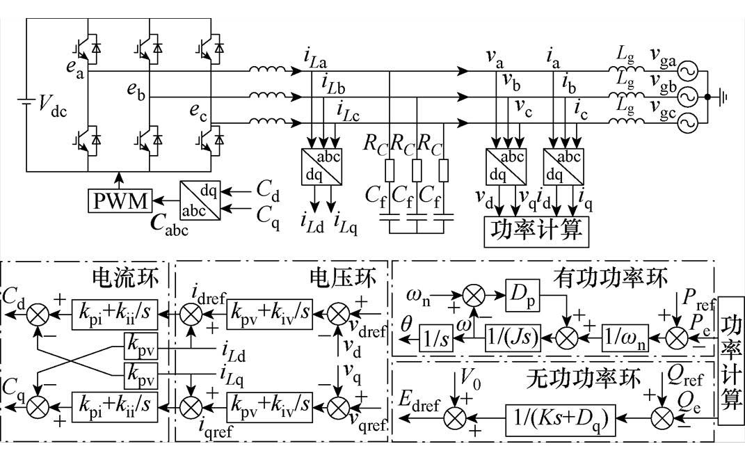
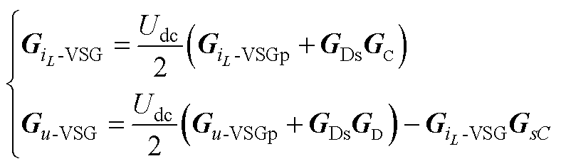
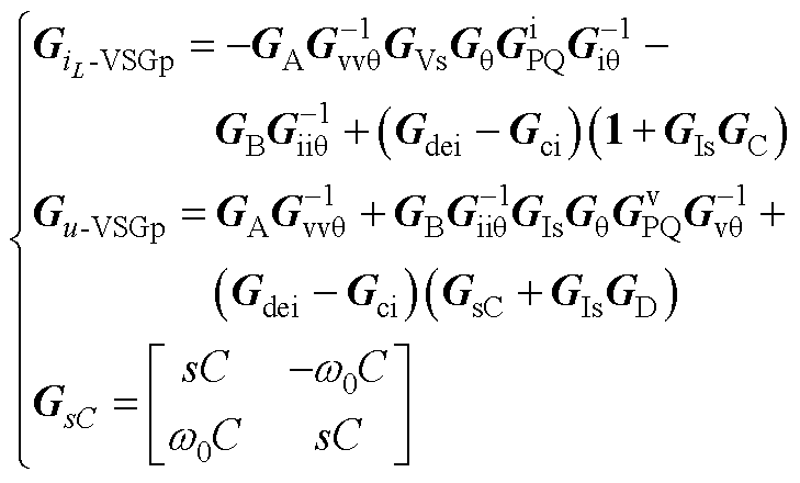
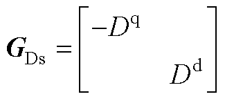
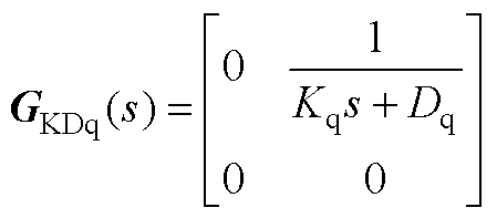
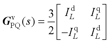
不同于GFL逆变器,GFM逆变器具有调频和调压组网能力,其控制策略主要有下垂控制和VSG控制等。鉴于VSG控制在实际中被广泛采用,故本文以VSG为讨论对象,附图2给出了VSG的控制框图,对于采用其他控制策略的GFM逆变器,仅需更改相应的传递函数即可,本文不在赘述。dq坐标系下基于VSG控制的GFM逆变器三相桥臂中点输出电压频域表达式为
 (17)
(17)
式中, 为基于VSG控制的GFM并网逆变器桥臂中点的输出电压列向量,
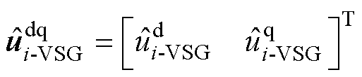 。与滤波电感电流反馈及电压前馈环节所对应的传递函数矩阵详细表达式如附录式(A2)、式(A3)所示。
关于滤波电感、滤波电容、采用直流电压外环控制的占空比以及直流电流的小信号表达式如附录式(A4)~式(A8)所示。
1.3.2 变流器并网系统的dq频域小信号模型
以图7所示的三变流器系统拓扑结构为例,说明多变流器并网系统小信号模型的建模过程。
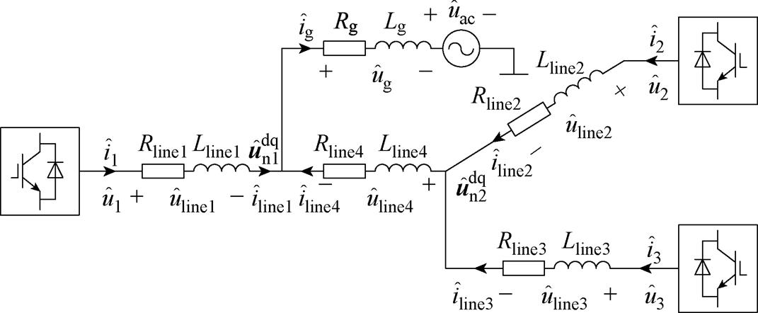
图7 三变流器系统拓扑结构
Fig.7 Topology of three converter grid-connected system
根据图7中各变流器与电力网络的连接关系,得
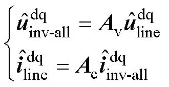 (18)
(18)
其中
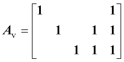
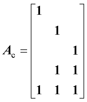
综合图3~图5和式(16)~式(18),可得图8所示的用于变流器并网系统鲁棒稳定性分析的整体模型。该模型同样适用于仅含单一GFL和GFM逆变器并网系统的鲁棒稳定性分析,只需令式(18)中表征变流器与电网连接关系的关联矩阵Av和Ac分别为2×2的单位矩阵即可。
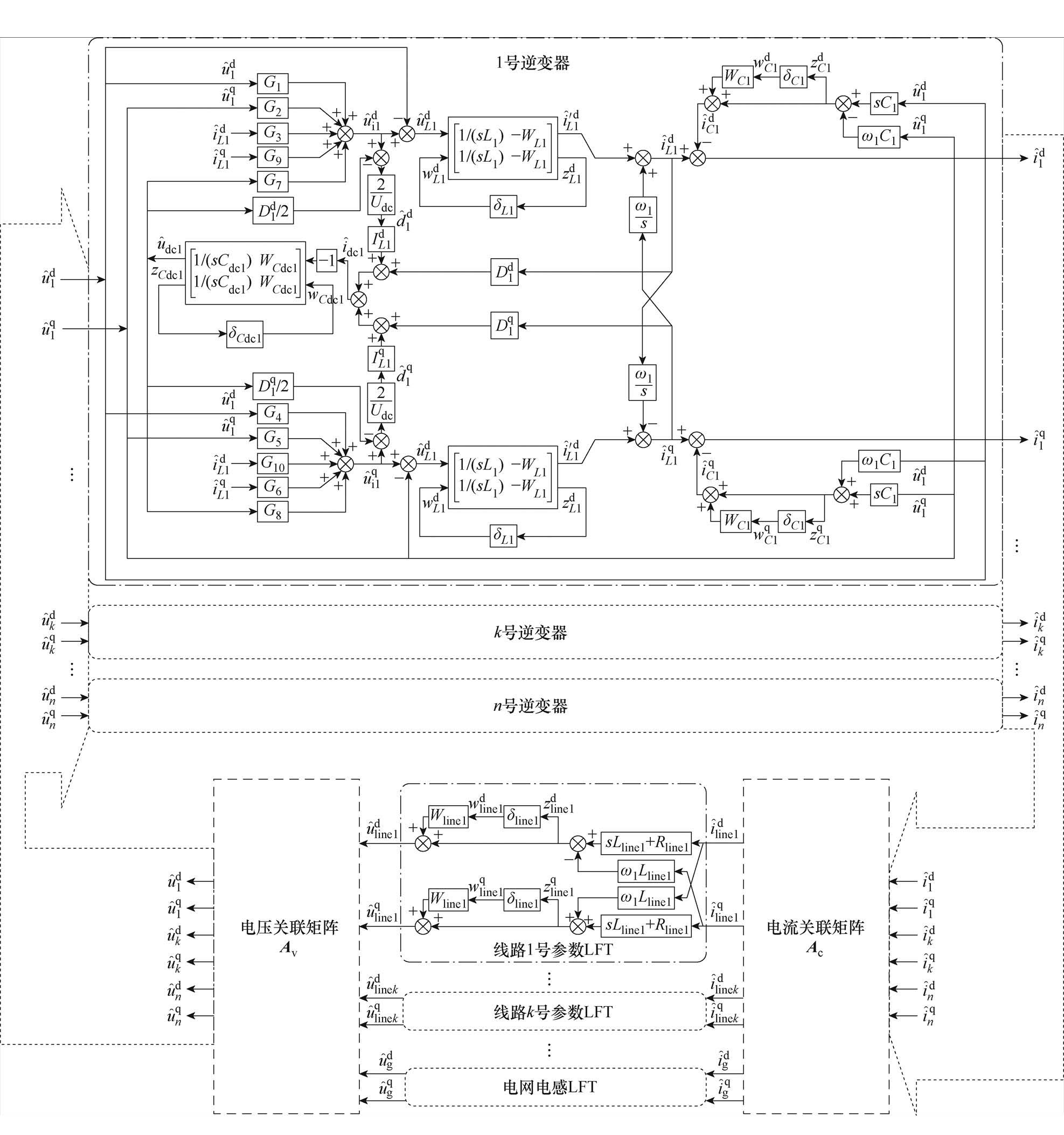
图8 多变流器并网系统鲁棒稳定性分析框图
Fig.8 Robust stability analysis model of multi-converter system
欲采用m分析对变流器并网系统进行鲁棒稳定性分析,还需建立如图8所对应的MD结构模型,本节将给出详细的推导过程。鉴于描述GFL的式(16)相对描述VSG的式(17)在形式上略显复杂,故下文将以GFL型逆变器为例进行推导,关于VSG的推导则完全类似,限于篇幅原因,本文不再赘述。
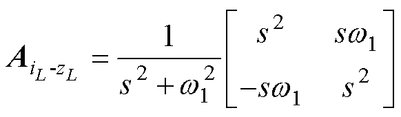
2.1.1 zinv和zline与winv的关系表达式Ⅰ
将式(8)第二式代入式(7)第一式,可得
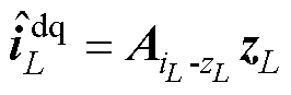 (19)
(19)
其中
再将式(10)和式(19)第二式代入式(A5),得
 (20)
(20)
其中
将式(20)代入式(18)第二式,有
 (21)
(21)
其中
最后将式(21)代入式(15)第一式,可得
 (22)
(22)
2.1.2 zinv和zline与winv和wline的关系表达式Ⅱ
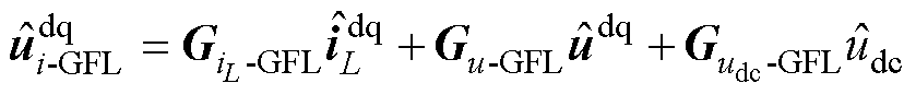
将式(12)和式(19)第二式代入式(16),有
 (23)
(23)
其中
结合式(23)和式(A4),可得
 (24)
(24)
其中
将式(12)第二式、式(19)和式(23)代入式(A8),可得
 (25)
(25)
其中
综合式(24)和式(25),有
 (26)
(26)
其中

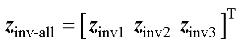
以三变流器系统为例,则有
 (27)
(27)
其中
将式(15)第二式和式(18)第一式代入式(27),可得
 (28)
(28)
将式(13)扩充为三变流器形式,即
 (29)
(29)
其中
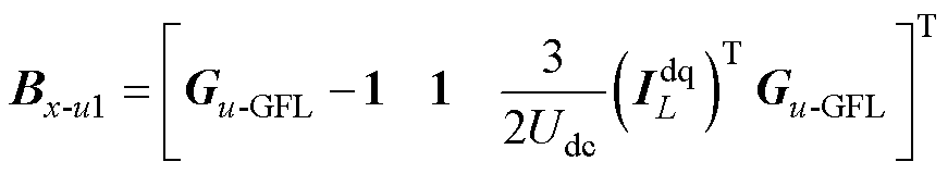
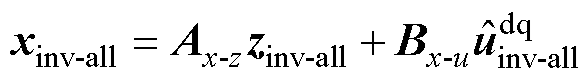
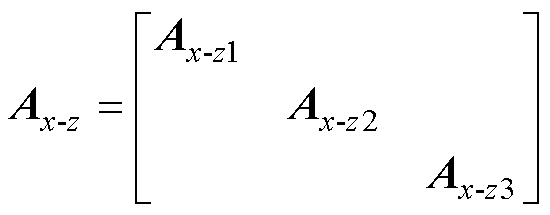
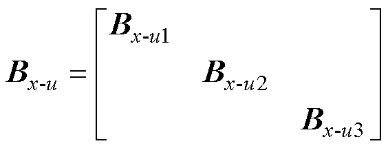
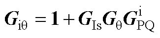
最终将式(28)代入式(29),经整理可得
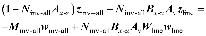 (30)
(30)
2.1.3 变流器并网系统的MD结构模型
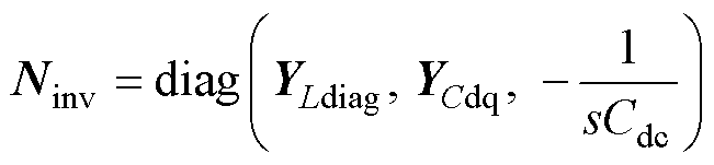
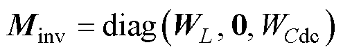
对于一个由n个逆变器和N条线路构成的多变流器并网系统,将全部的参数不确定性写为如下对角矩阵,即
 (31)
(31)
式中, 为变流器滤波电感、电容及直流电容参数扰动矩阵,k=1, 2,…,
 ;
; 为电力网络中线路参数及电网电感的参数扰动矩阵,
 。
。
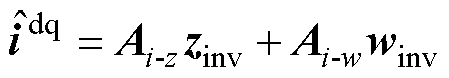
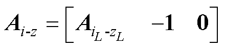
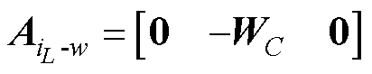
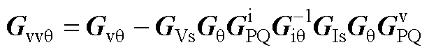
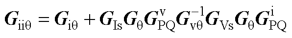
综合式(22)和式(30),可得
 (32)
(32)
式中, ,
, ;M(s)为系统的开环传递函数,
 ,
,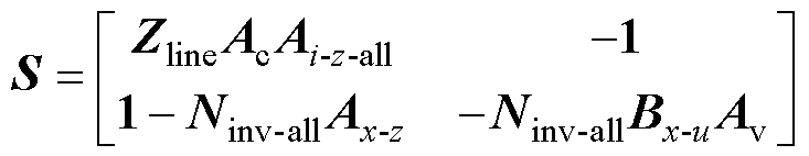 ,
,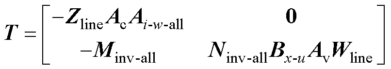 。
。
结合式(32),即可获得图8所示变流器并网系统模型的MD结构模型如图9所示。
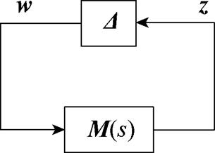
图9 变流器并网系统鲁棒稳定性分析MD结构框图
Fig.9 MD structure of converter grid-connected system for robust analysis
鲁棒稳定性实则是讨论系统在参数摄动 (在||||∞范数意义下)时的稳定性,其前提是系统在标称参数下满足内部稳定,即开环系统M(s)稳定[22]。
由图9所示系统框图可知,系统闭环极点由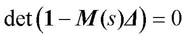 决定,若某个位于复平面右半平面的复变量s满足
 ,则系统将不稳定。为评估系统的鲁棒稳定性,m分析理论所定义的系统SSV[22]为
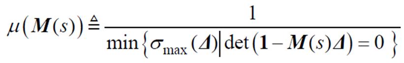 (33)
(33)
式中, 为最大奇异值。当SSV≥1时,系统将发生振荡甚至失稳,特别地,对于某一复频率sc=jwc= j2pfc,若SSV=1,则意味着
 ,说明系统存在纯虚极点,此时系统处于临界稳定状态。
由SSV的定义可知,利用SSV的倒数可评估系统的稳定裕度,即
 (34)
(34)
综上所述,采用本文方法分析逆变器并网系统鲁棒稳定性的步骤可总结为:
(1)计算标称模型的稳态工作点,并在工作点附近对系统进行线性化,建立dq坐标系下的系统频域小信号模型,即式(16)、式(17)、式(A4)~式(A8)。
(2)设置相应参数的加权矩阵W为不确定程度,利用式(32)获得不确定系统MD结构的开环传递函数M(s)。
(3)基于m分析,利用式(33)获得SSV-f频率特性曲线,依据SSV峰值评估系统的鲁棒稳定性,并利用式(34)得到系统的稳定裕度。
为充分验证本文方法,第3节将针对单变流器并网系统进行讨论,以验证所建立的单GFL和单GFM变流器小信号模型以及本文方法在分析单变流器并网系统鲁棒稳定性的准确性。在此基础上,第4节将本文方法应用于计及多参数不确定性的多变流器并网系统的鲁棒稳定性分析,进一步对本文方法的正确性进行验证。
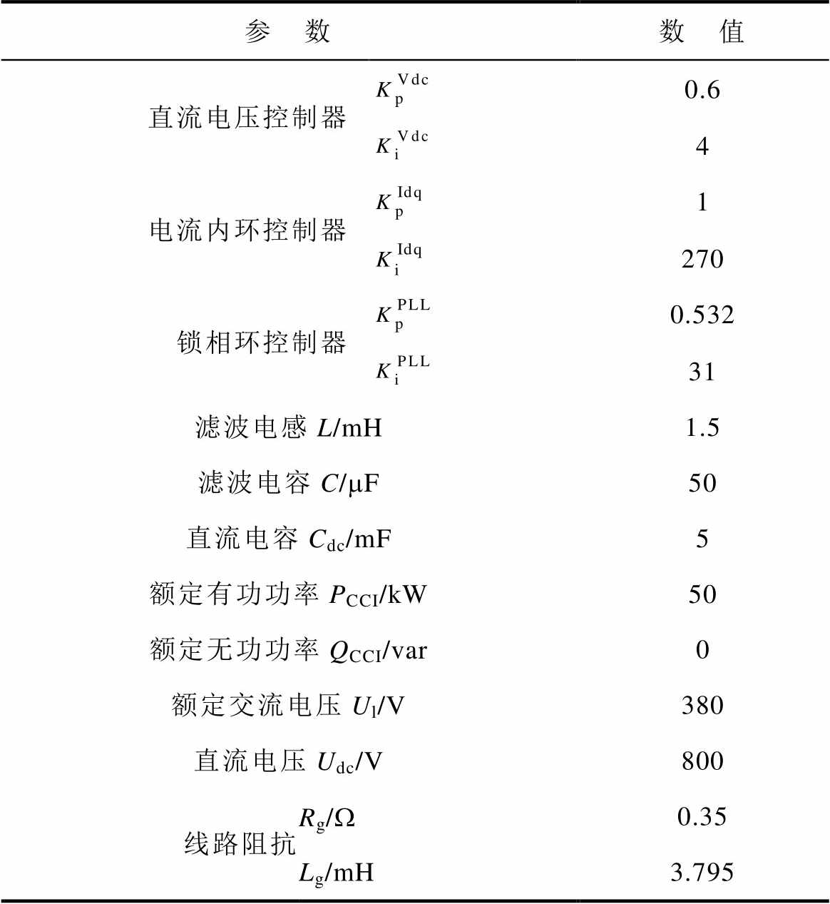
本算例旨在讨论单个GFL逆变器并网系统的鲁棒小干扰稳定性。算例中逆变器的标称电气参数和控制器的PI参数列于附表1。在Matlab/Simulink搭建系统仿真模型,通过分析滤波电感不确定性对系统稳定性的影响,以验证本文所建模型及分析方法的正确性。0.5 s前,电网电感为3 mH,对应的短路比(Short Circuit Ratio, SCR)为3.06,0.5 s时将线路电感增至3.795 mH(SCR=2.42),在标称参数下(滤波电感标称值为1.5 mH)输出有功和无功功率波形如图10所示,可以看出,经过短暂的过渡过程,系统可逐渐恢复稳定,表明标称系统满足内部稳定。
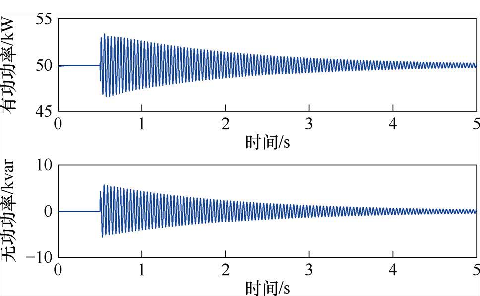
图10 标称参数下的有功功率和无功功率波形(GFL)
Fig.10 Active and reactive power waveforms of nominal system (GFL)
分别取滤波电感不确定程度为5%、10%和15%三种情况,图11给出了采用本文方法所获得的SSV随频率变化的曲线,可以看出,SSV将随滤波电感不确定程度的增加而整体变大。对于滤波电感不确定程度为10%的系统,其峰值约等于1,所对应的频率fc=25.5 Hz,可判定此时系统应近似处于临界稳定状态。
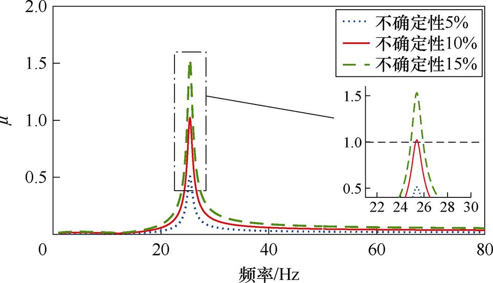
图11 不同滤波电感不确定性下的SSV-f曲线(GFL)
Fig.11 SSV-f curves with different parametric uncertainties of filter inductance L (GFL)
在0.5 s时将电网电感增加至3.795 mH,仿真所得到的有功功率和并网电流波形如图12所示。可以看出,当滤波电感增加5%时,系统可恢复稳定,但暂态过程相比标称系统所需时间更长;当滤波电感为标称值的1.1倍时,系统将持续振荡而无法恢复稳定;对于滤波电感不确定程度为15%的系统,系统无法再恢复到稳定状态。上述结果说明随着滤波电感不确定度的增加,系统整体呈现稳定→临界稳定→失稳趋势,稳定性逐渐变差。
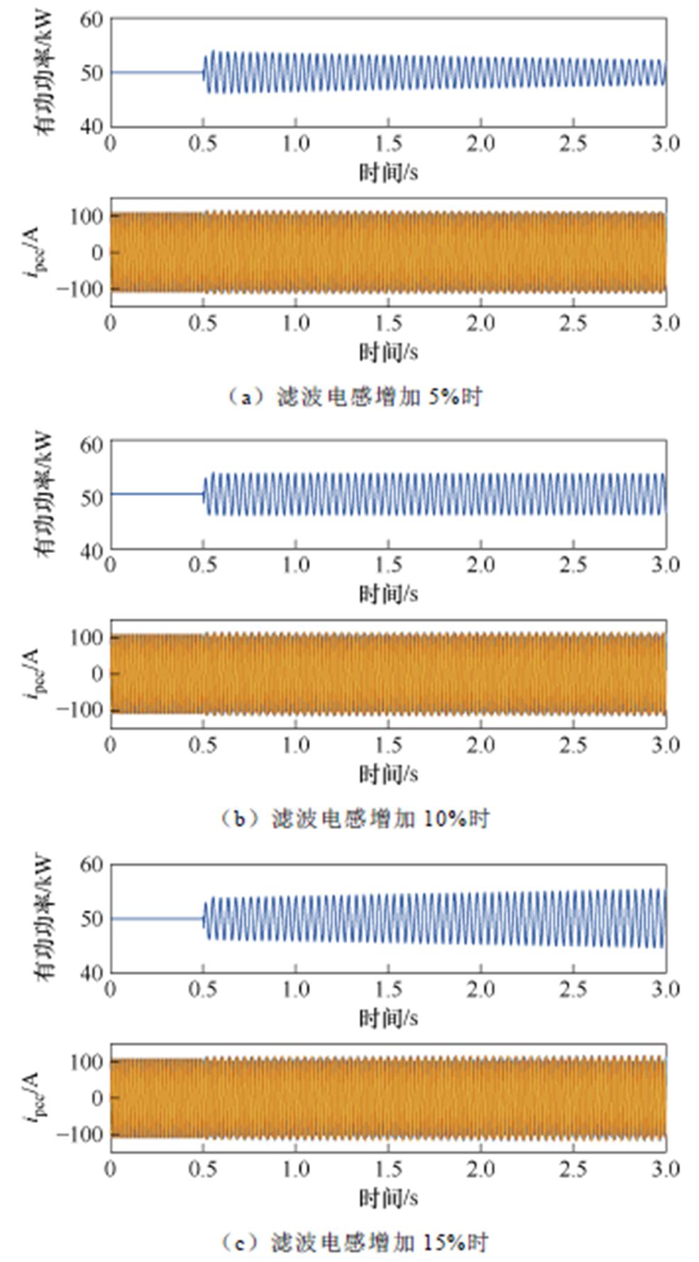
图12 不同滤波电感不确定性下的有功功率和并网电流波形(GFL)
Fig.12 Active power and grid current waveforms of different parametric uncertainties of filter inductance L (GFL)
对滤波电感增加为标称值的1.1倍场景下的并网电流进行快速傅里叶变换(Fast Fourier Transform, FFT)分析,结果如图13所示,可见系统并网电流中存在频率为fp1≈25 Hz和fp2≈75 Hz的次同步和超同步振荡分量。该abc坐标系下的振荡频率与图11所获得dq坐标系下SSV的峰值频率fc= 25.5 Hz相一致,即fp1≈fc+50 Hz=75.5 Hz和fp2≈50 Hz-fc= 24.5 Hz,说明SSV-f曲线具备表征系统的振荡模态的能力。
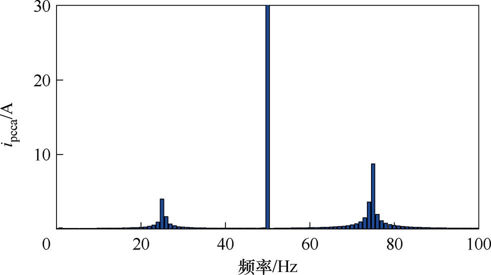
图13 滤波电感不确定度为10%下电网电流的FFT分析(GFL)
Fig.13 FFT analysis of grid current with 10% uncertainty (GFL)
综合上述分析,说明了本文方法在用于分析单个GFL逆变器并网系统的鲁棒小干扰稳定性时的正确性。
本算例旨在讨论单个基于VSG控制的GFM逆变器并网系统的鲁棒小干扰稳定性。在Matlab/ Simulink中搭建仿真模型,其中VSG的电气和控制参数列于附表2。0.5 s前,电网电感取0.447 mH(SCR=50.56),0.5 s时,电网电感减小至0.147 mH(SCR=62.53),标称参数下(滤波电感标称值为1.5 mH)的有功和无功功率波形如图14所示,系统经过小扰动后可恢复稳定,说明标称系统满足内部稳定。
当计及滤波电感不确性时(不确定程度分别取5%、10%和15%),图15展示了在相同扰动下的并网电流波形,同样表现为随着不确定程度的增加而稳定性变差。
采用本文方法获得的SSV-f曲线如图16所示,当滤波电感不确定程度为10%时,SSV的峰值略大于1且其对应的频率为fc=10.5 Hz,可判定此时系统近似处于临界稳定状态。对图15b的电网电流进行FFT分析,结果如图17所示,可知存在fp1=39 Hz和fp2=61 Hz系次同步和超同步振荡分量,该频率分析结果与图16所给出SSV-f峰值频率相吻合,即 fp1≈fc+50 Hz=60.5 Hz和fp2≈50 Hz-fc=39.5 Hz。说明了本文方法在分析GFM逆变器系统时的正确性。
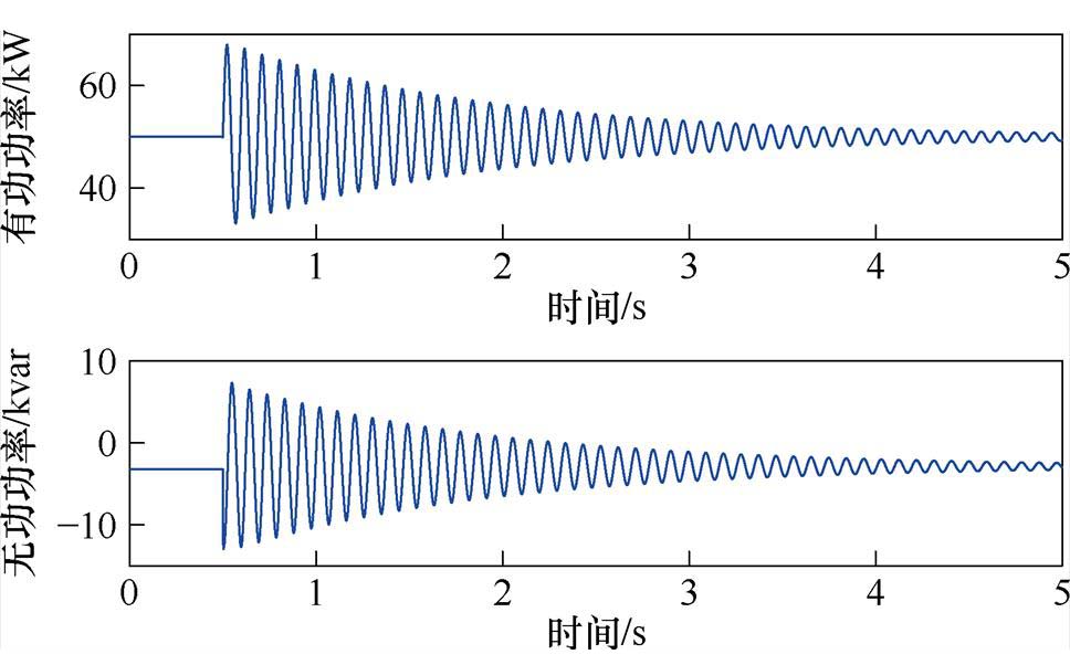
图14 标称参数下的有功功率和无功功率波形(GFM)
Fig.14 Active and reactive power waveforms of nominal system (GFM)
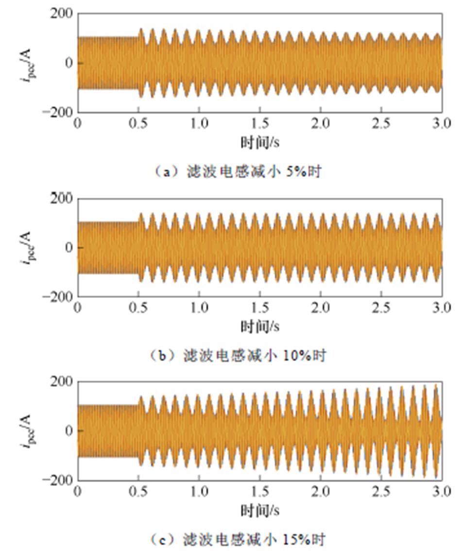
图15 不同滤波电感不确定性下的并网电流波形(GFM)
Fig.15 Grid current waveforms of different parametric uncertainties of filter inductance L (GFM)
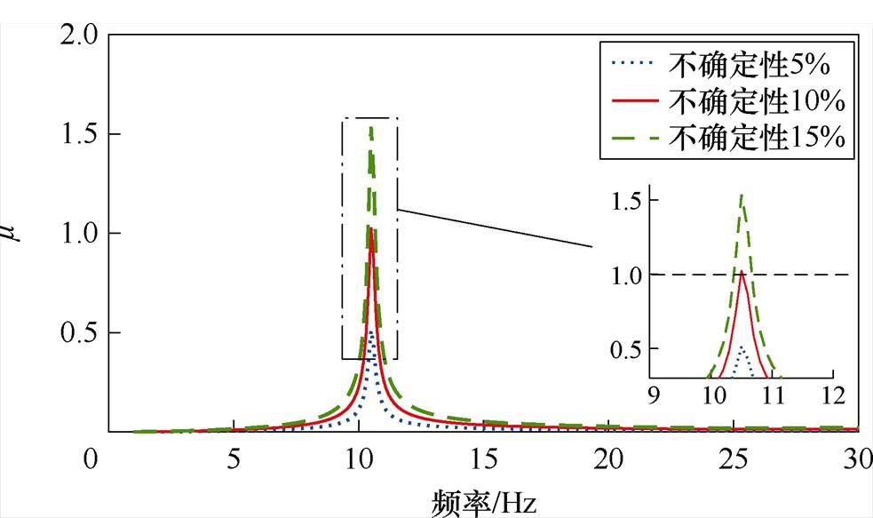
图16 不同滤波电感不确定性下的SSV-f曲线(GFM)
Fig.16 SSV-f curves with different parametric uncertainties of filter inductance L (GFM)
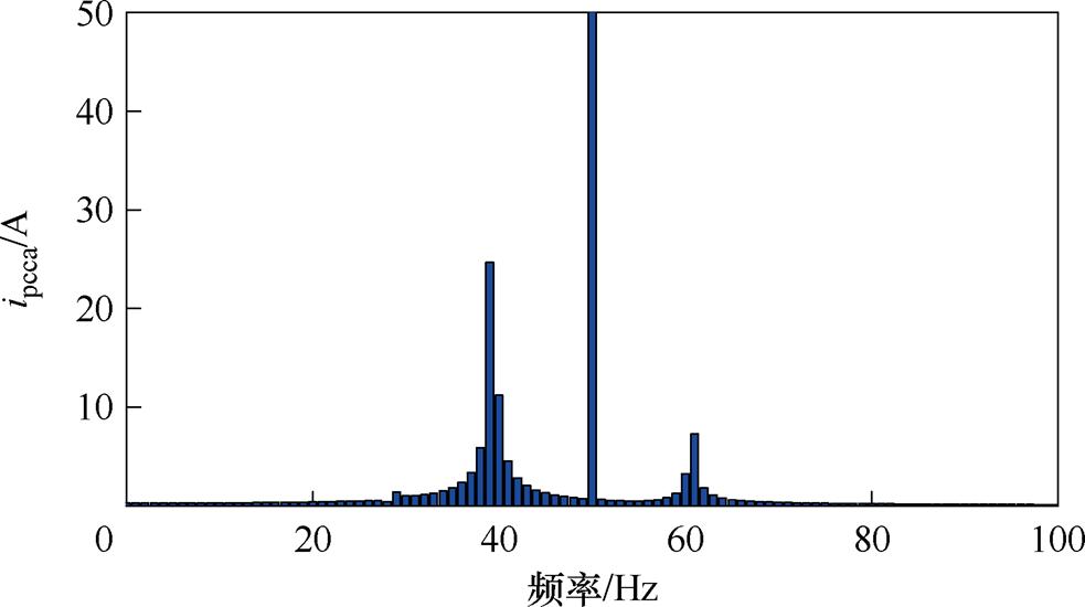
图17 不确定程度为10%下的电网电流的FFT分析(GFM)
Fig.17 FFT analysis of grid current with 10% uncertainties (GFM)
本节的讨论对象为计及多参数不确定性的多变流器并网系统,以进一步验证方法的正确性。
本算例为由8个GFL和2个GFM逆变器构成的十变流器系统,拓扑结构如图18所示,用以分析含有多个GFL逆变器和GFM变流器系统的鲁棒小干扰稳定性。各变流器电气标称参数、PI控制参数以及线路参数标称值见附表3和附表4。
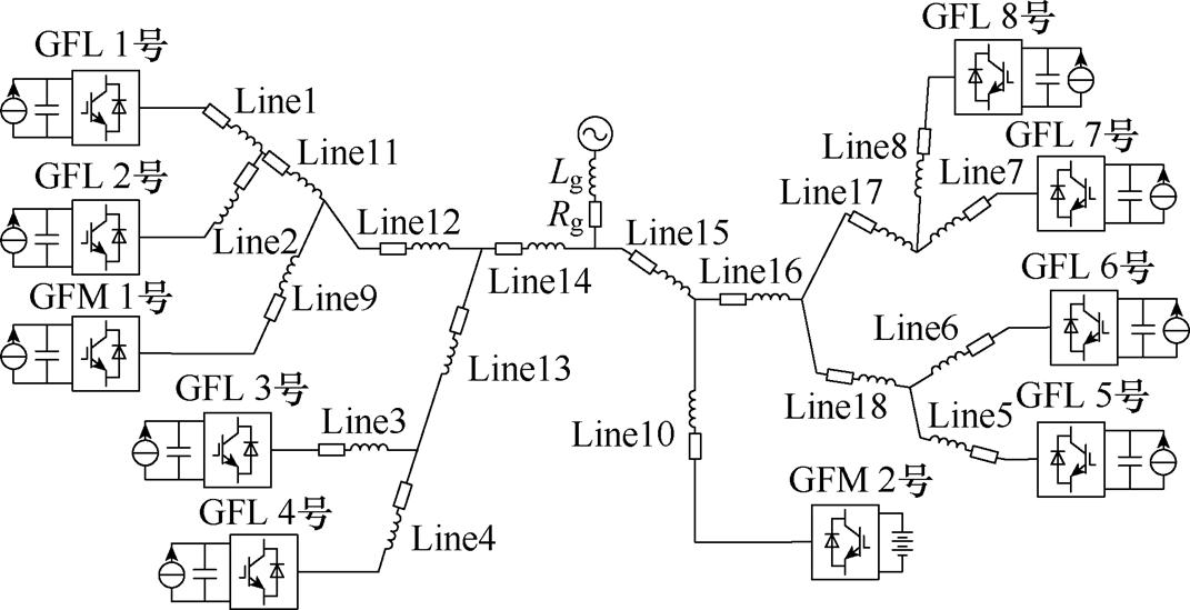
图18 十变流器并网系统拓扑结构
Fig.18 Topology of ten-converter grid-connected system
在Matlab/Simulink搭建标称系统仿真模型,0.5 s前,电网电感为0.32 mH,0.5 s时,电网电感增加至0.45 mH,得到并网总功率和总电流如图19所示,可以看出系统经扰动后可逐渐恢复稳定,表明标称系统满足内部稳定。
图20给出了滤波电感和电容、直流侧电容和线路参数不确定性程度分别为10%、10%、15%和5%下的SSV-f曲线。可以看出,在频率约为27.3 Hz处SSV出现峰值,其大小略超过1,基于m分析可知此场景下系统近似处于临界稳定状态。
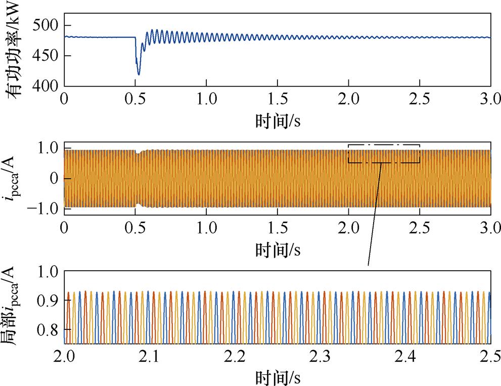
图19 标称系统的并网总功率和总电流仿真波形(GFL+GFM)
Fig.19 Simulation waveforms of active power and grid current with nominal system (GFL+GFM)
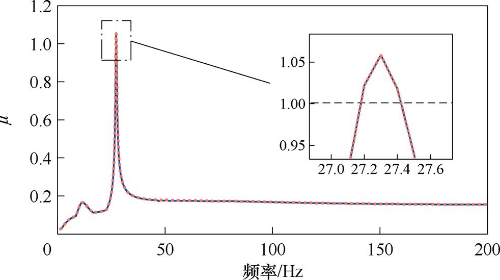
图20 计及多参数不确定性系统的SSV-f仿真曲线(GFL+GFM)
Fig.20 SSV-fsimulation curve with multiple parametric uncertainties (GFL+GFM)
图21给出了计及上述多参数不确定性的并网电流仿真波形,相应的FFT分析结果如图22所示。
由图22可以看出,系统在发生小干扰后呈现等幅振荡,说明系统近似处于临界稳定状态,其与针对图20进行分析所得的结论相一致。结合图22的频谱分析可知,系统所含的次同步和超同步振荡频率分别为fp1=22 Hz和fp2=78 Hz,亦与图20中SSV的峰值频率fc=27.3 Hz基本吻合,即fp1≈fc+50 Hz= 77.3 Hz和fp2≈50 Hz-fc=22.7 Hz。综合上述分析,说明了本文方法可实现多个GFL逆变器和GFM逆变器共同构成的并网系统鲁棒小干扰稳定性的可靠评估。
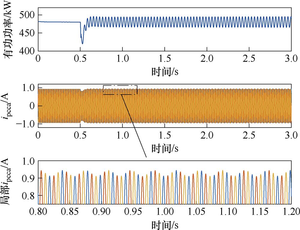
图21 计及参数不确定性系统的总并网总功率和总电流仿真波形(GFL+GFM)
Fig.21 Simulation waveforms of active power and grid current of system with multiple parametric uncertainties (GFL+GFM)
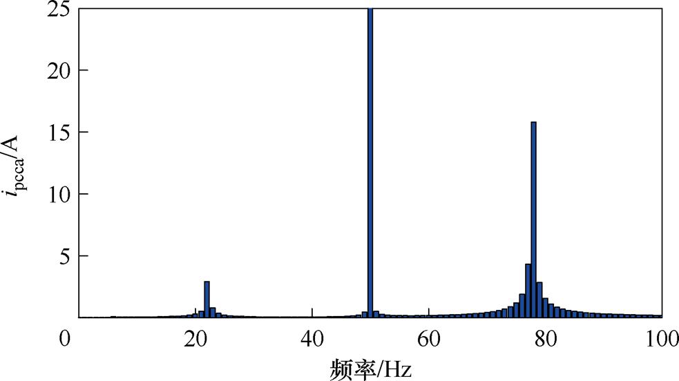
图22 总并网电流的FFT仿真分析(GFL+GFM)
Fig.22 FFT simulation analysis of grid current (GFL+GFM)
鉴于HIL实验平台最多仅可开展6个变流器的实验,本节针对由4个GFL逆变器和2个采用VSG控制的GFM逆变器构成的六变流器系统开展HIL实验。系统拓扑结构如图23所示,各变流器的标称电气参数、控制器PI参数以及线路参数标称值见附表5和附表6。
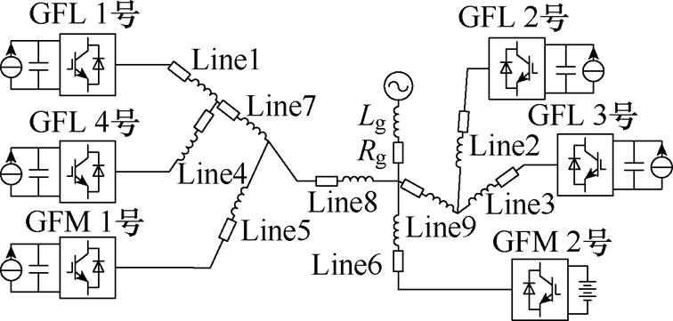
图23 六变流器并网系统拓扑结构
Fig.23 Topology of six-converter grid-connected system
HIL实验平台如图24所示,平台采用NI PIXe- 1082实时仿真机,该平台与Matlab/Simulink仿真的不同之处在于,电气回路的仿真步长为1 ms,而控制器载波频率和采样频率均为10 kHz,因此,HIL实验相比于Matlab/Simulink仿真所采用的100 kHz更加符合实际情况。
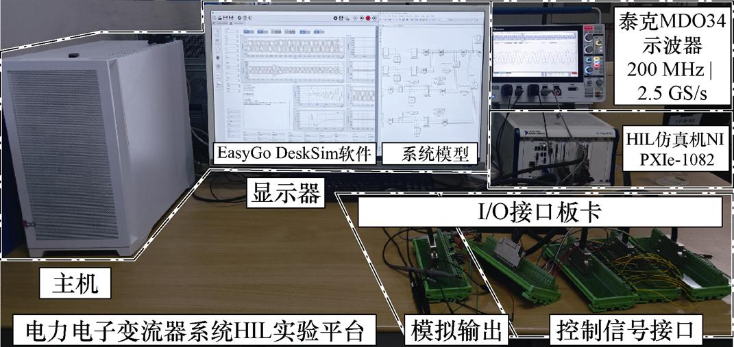
图24 HIL实验平台
Fig.24 HIL experiment platform
标称参数下,电网电感由0.5 mH减小至0.2 mH时,并网电流波形如图25所示,可见经扰动后系统仍可恢复稳定运行,可知标称系统满足内部稳定。
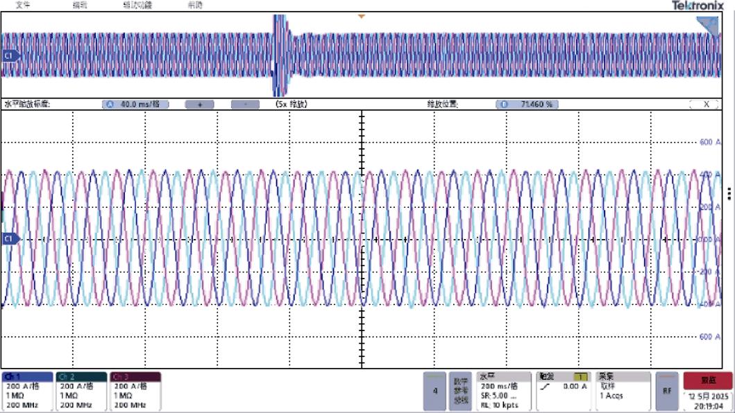
图25 标称系统的总并网电流HIL实验波形(GFL+GFM)
Fig.25 Experiment waveforms of grid current of nominal system in HIL (GFL+GFM)
计及多参数不确定性(滤波电感和电容、GFL逆变器直流侧电容和线路参数不确定性程度分别为10%、10%、15%和5%)下的并网总电流波形如图26所示。可以看出,系统在扰动后波形发生畸变,表现为等幅振荡。对其进行FFT分析所得频谱如图27所示,可见系统将发生次同步和超同步振荡,频率分别为fp1=34 Hz和fp2=66 Hz。
图28给出了考虑上述多参数不确定性的多变流器系统的SSV-f实验曲线。可以看出,SSV约在fc=15.5 Hz处出现峰值,其数值略大于1,基于m分析可知,此场景下系统近似处于临界稳定状态,与图26和图27的仿真结果基本吻合,即fp1≈fc+50 Hz= 65.5 Hz和fp2≈50 Hz-fc=34.5 Hz,综合以上分析,验证了本文方法在分析同时含有GFL和GFM逆变器的并网系统鲁棒小干扰稳定性的准确性。
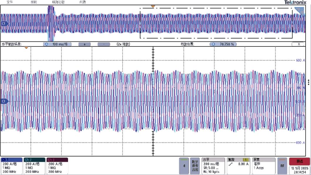
图26 计及多参数不确定性的总并网电流HIL实验波形(GFL+GFM)
Fig.26 Experiment waveforms of grid current with multiple parametric uncertainties in HIL experiment (GFL+GFM)
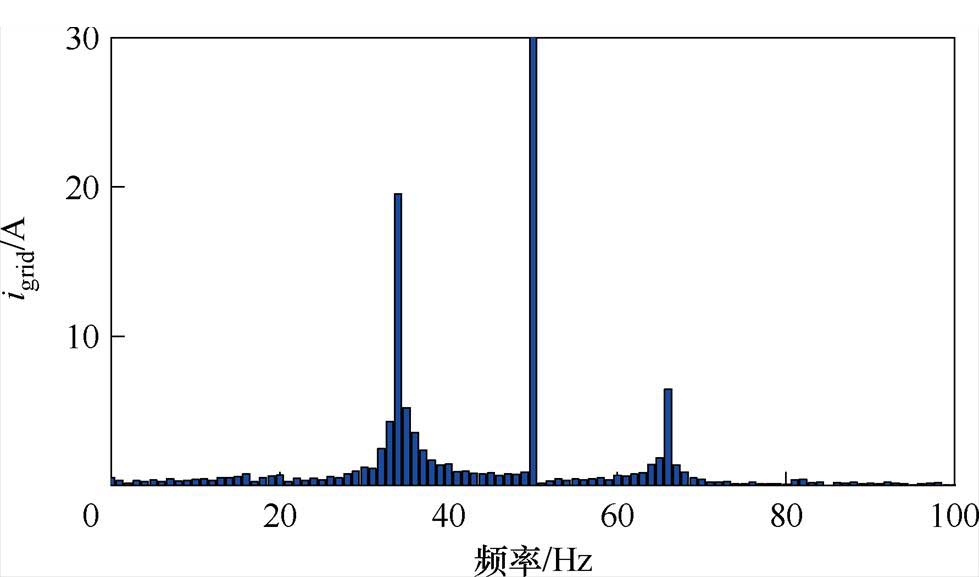
图27 总并网电流的FFT实验分析(GFL+GFM)
Fig.27 FFT experimental analysis of grid current (GFL+GFM)
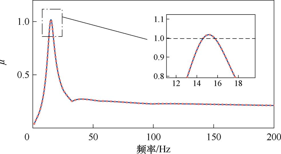
图28 计及多参数不确定性的SSV-f实验曲线(GFL+GFM)
Fig.28 SSV-f experimental curve with multiple parametric uncertainties (GFL+GFM)
本文针对计及多参数不确定性的变流器并网系统dq小信号建模和鲁棒稳定性分析方法进行了全面系统的研究,所得结论如下:
1)基于LFT和谐波线性化建模方法,本文提出了一种可计及多参数不确定性的逆变器并网系统dq坐标系频域小信号模型。该模型可准确地描述系统在小干扰下的动态特性,同时避免了状态空间法针对多变流器系统建模易导致的“维数灾”问题。而且,相比于现有文献所采用的对变流器导纳进行“宏观”的摄动方式,本文方法将各内部参数摄动量“拉出”系统,可“显式”地讨论各参数不确定性对系统小干扰稳定性的影响。
2)经推导获得了不确定系统的MD结构模型及其传递函数,基于m分析理论,提出了一种用于分析并网逆变器系统鲁棒稳定性的频域分析方法。该方法可准确地分析计及滤波器参数、电力网络参数等多参数不确定性的变流器并网系统的鲁棒稳定性,同时利用SSV可实现系统稳定裕度的量化评估。该方法相比于蒙特卡洛法,避免了因参数调整所导致的繁琐线性化建模过程,有效降低了工作量。
3)结合典型算例,开展了Matlab/Simulink仿真和HIL实验,验证了本文所提方法应用于计及多参数不确定性的变流器并网系统小干扰稳定性分析的正确性。通过对比分析标称系统和不确定系统的结果,阐明了在开展变流器并网系统小干扰稳定性时,计及电气元件参数所存在的不确定性十分必要。同时,通过对比SSV-f曲线峰值频率和算例波形FFT分析结果,说明了SSV-f频率特性曲线具备预测系统振荡模态的功能。
附 录
1. 跟网型[3]和构网型[45]变流器拓扑及控制策略控制框图如附图1和附图2所示。
附图1 跟网型变流器拓扑结构及控制策略框图
App.Fig.1 Topology and control strategy of GFL inverter
2. 式(16)中系数矩阵的详细表达式及滤波器和直流电流小信号表达式为
附图2 构网型变流器拓扑结构及控制策略框图
App.Fig.2 Topology and control strategy of GFM inverter
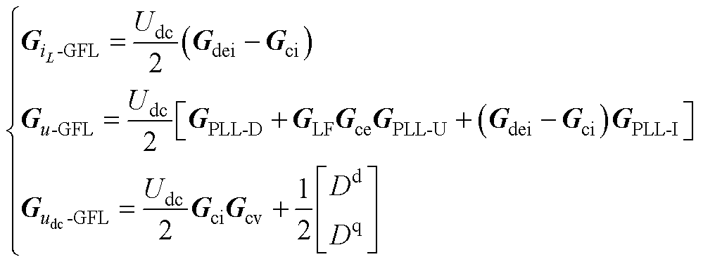 (A1)
(A1)
其中
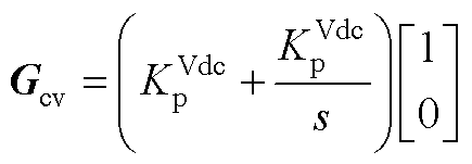
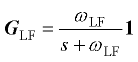
式中, 为电压前馈通道数字低通滤波器的截止频率。
式(17)中各传递函数的详细表达式为
 (A2)
(A2)
其中
式中,各系数矩阵为
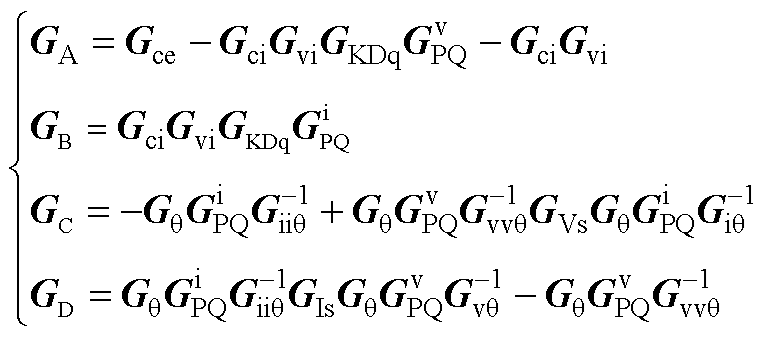 (A3)
(A3)
其中
滤波电感两端电压的KVL方程为
 (A4)
(A4)
滤波电容的KCL方程为
 (A5)
(A5)
式中, 为dq坐标系下的并网电流列向量。
对于采用直流电压外环控制的GFL逆变器,其直流电流的小信号表达式为
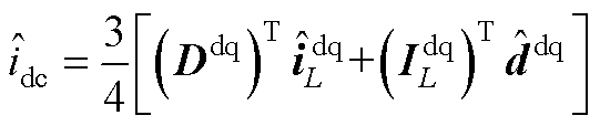 (A6)
(A6)
式中,占空比稳态值及其小信号表达式分别为
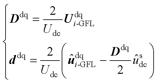 (A7)
(A7)
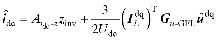
将式(A7)代入式(A6),可得直流电流表达式为
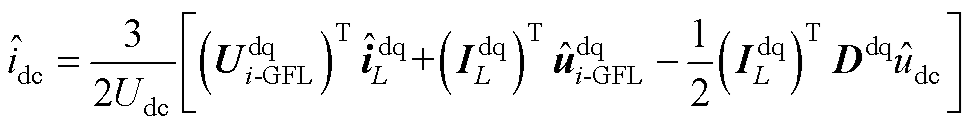 (A8)
(A8)
3. 仿真算例和HIL实验中各变流器及电力网络线路标称参数见附表1~附表6。
附表1 算例3.1节中GFL逆变器电气和控制参数
App.Tab.1 Parameters of GFL inverter in example 3.1
参 数数 值 直流电压控制器0.6 4 电流内环控制器1 270 锁相环控制器0.532 31 滤波电感L/mH1.5 滤波电容C/mF50 直流电容Cdc/mF5 额定有功功率PCCI/kW50 额定无功功率QCCI/var0 额定交流电压Ul/V380 直流电压Udc/V800 线路阻抗Rg/W0.35 Lg/mH3.795
附表2 算例3.2节中VSG电气和控制参数
App.Tab.2 Parameters of VSG in example 3.2
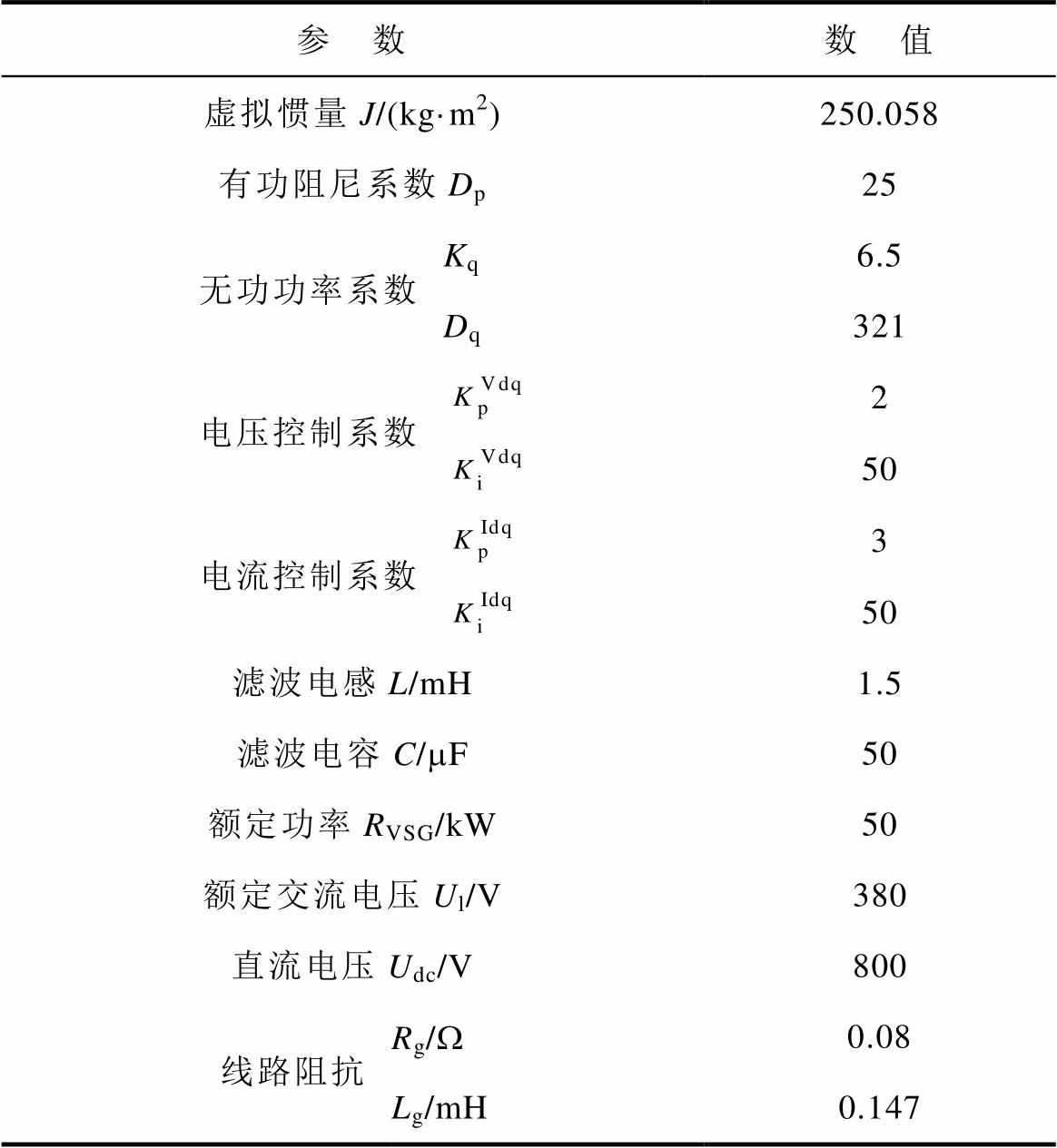
参 数数 值 虚拟惯量J/(kg·m2)250.058 有功阻尼系数Dp25 无功功率系数Kq6.5 Dq321 电压控制系数2 50 电流控制系数3 50 滤波电感L/mH1.5 滤波电容C/mF50 额定功率RVSG/kW50 额定交流电压Ul/V380 直流电压Udc/V800 线路阻抗Rg/W0.08 Lg/mH0.147
附表3 算例4.1节中GFL逆变器和VSG电气和控制参数
App.Tab.3 Parameters of GFL inverter and VSG in example 4.1
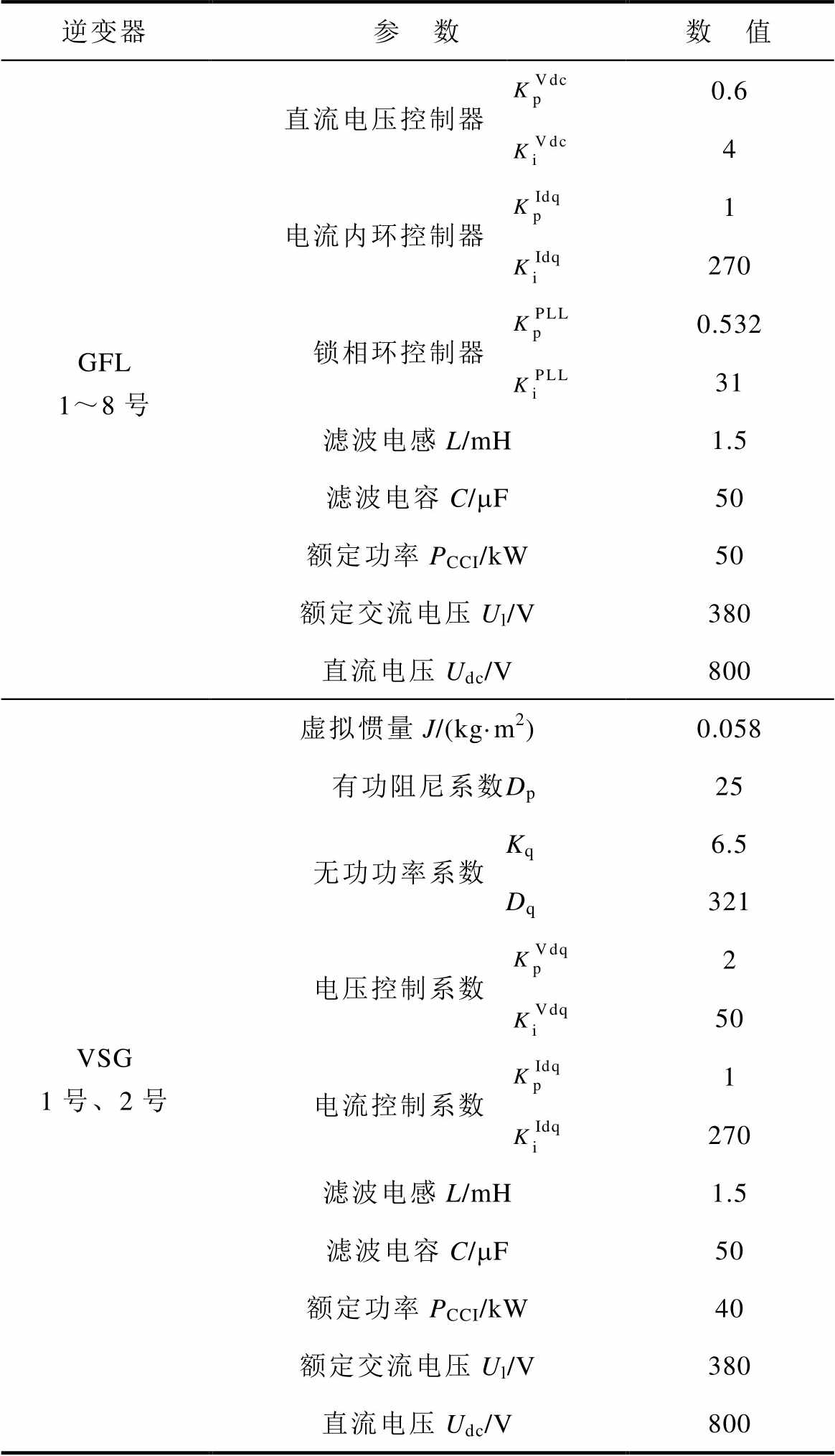
逆变器参 数数 值 GFL 1~8号直流电压控制器0.6 4 电流内环控制器1 270 锁相环控制器0.532 31 滤波电感L/mH1.5 滤波电容C/mF50 额定功率PCCI/kW50 额定交流电压Ul/V380 直流电压Udc/V800 VSG 1号、2号虚拟惯量J/(kg·m2)0.058 有功阻尼系数Dp25 无功功率系数Kq6.5 Dq321 电压控制系数2 50 电流控制系数1 270 滤波电感L/mH1.5 滤波电容C/mF50 额定功率PCCI/kW40 额定交流电压Ul/V380 直流电压Udc/V800
附表4 算例4.1节中电力网络线路参数
App.Tab.4 Parameters of power network in example 4.1
线路阻抗数 值 ZLine1R1/W0.01 L1/mH0.1 ZLine2R2/W0.01 L2/mH0.1 ZLine3R3/W0.01 L3/mH0.1 ZLine4R4/W0.01 L4/mH0.1 ZLine5R5/W0.01 L5/mH0.1
(续)
线路阻抗数 值 ZLine6R6/W0.01 L6/mH0.1 ZLine7R7/W0.01 L7/mH0.1 ZLine8R8/W0.01 L8/mH0.1 ZLine9R9/W0.01 L9/mH0.1 ZLine10R10/W0.01 L10/mH0.4 ZLine11R11/W0.1 L11/mH0.3 ZLine12R12/W0.1 L12/mH0.3 ZLine13R13/W0.1 L3/mH0.3 ZLine14R14/W0.04 L14/mH0.2 ZLine15R15/W0.1 L15/mH0.3 ZLine16R16/W0.01 L16/mH0.1 ZLine17R17/W0.01 L17/mH0.1 ZLine18R18/W0.01 L18/mH0.1 ZLgR19/W0.04 L19/mH0.45
附表5 HIL实验中GFL和VSG电气和控制参数
App.Tab.5 Parameters of GFL inverter and VSG in HIL experiment
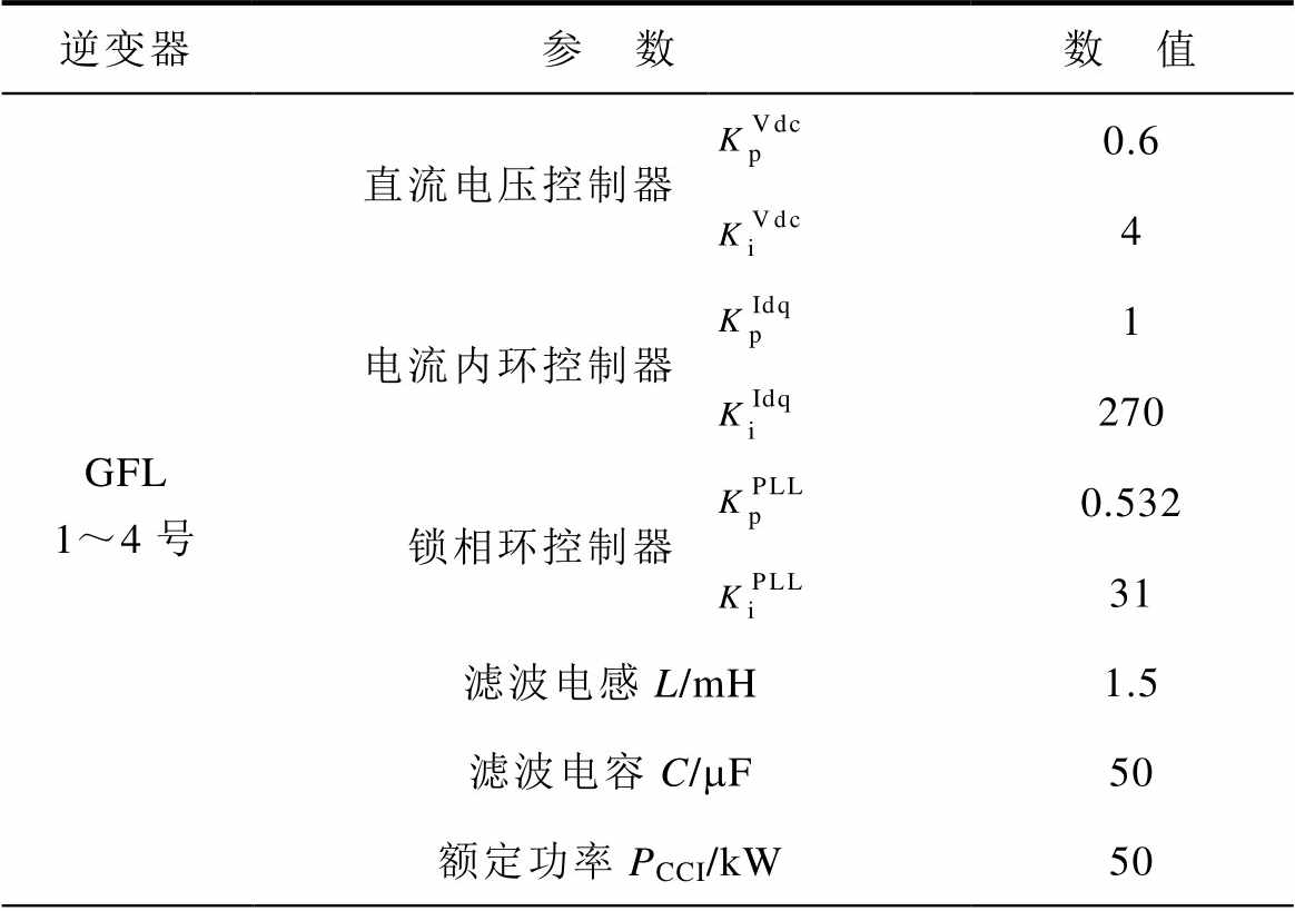
逆变器参 数数 值 GFL 1~4号直流电压控制器0.6 4 电流内环控制器1 270 锁相环控制器0.532 31 滤波电感L/mH1.5 滤波电容C/mF50 额定功率PCCI/kW50
(续)
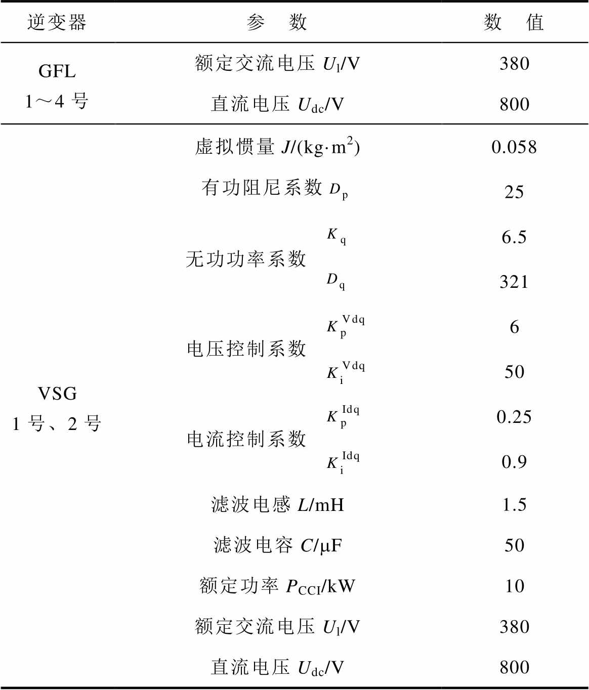
逆变器参 数数 值 GFL 1~4号额定交流电压Ul/V380 直流电压Udc/V800 VSG 1号、2号虚拟惯量J/(kg·m2)0.058 有功阻尼系数25 无功功率系数6.5 321 电压控制系数6 50 电流控制系数0.25 0.9 滤波电感L/mH1.5 滤波电容C/mF50 额定功率PCCI/kW10 额定交流电压Ul/V380 直流电压Udc/V800
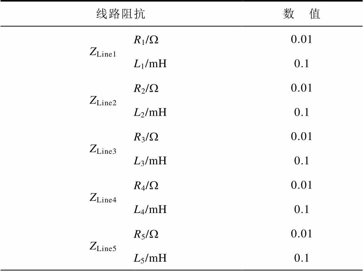
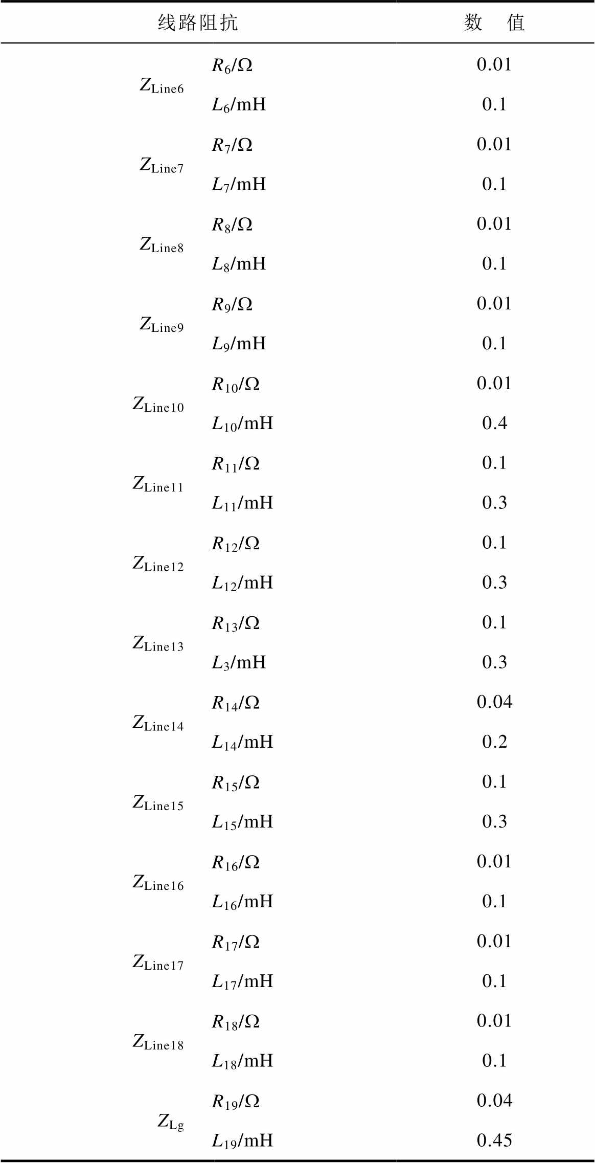
附表6 HIL实验中电力网络的线路参数
App.Tab.6 Parameters of power network in HIL experiment
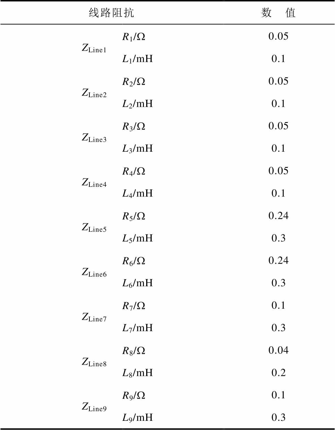
线路阻抗数 值 ZLine1R1/W0.05 L1/mH0.1 ZLine2R2/W0.05 L2/mH0.1 ZLine3R3/W0.05 L3/mH0.1 ZLine4R4/W0.05 L4/mH0.1 ZLine5R5/W0.24 L5/mH0.3 ZLine6R6/W0.24 L6/mH0.3 ZLine7R7/W0.1 L7/mH0.3 ZLine8R8/W0.04 L8/mH0.2 ZLine9R9/W0.1 L9/mH0.3
参考文献
[1] 唐宇, 胡光, 刘永江, 等. 基于特征子系统的跟网/构网设备混合外送系统小干扰稳定性分析方法[J].电工技术学报, 2025, 40(9): 2766-2779.
Tang Yu, Hu Guang, Liu Yongjiang, et al. Small- signal stability analysis method for hybrid grid- following/grid forming delivery systems based on eigen-subsystem[J]. Transactions of China Electro- technical Society, 2025, 40(9): 2766-2779.
[2] 谢小荣, 李浩志, 张丹, 等. 新型电力系统稳定器研究初探[J]. 电力系统自动化, 2024, 48(23): 156- 166.
Xie Xiaorong, Li Haozhi, Zhang Dan, et al. Preliminary study on stabilizer for new power systems[J]. Automation of Electric Power Systems, 2024, 48(23): 156-166.
[3] 黄萌, 舒思睿, 李锡林, 等. 面向同步稳定性的电力电子并网变流器分析与控制研究综述[J]. 电工技术学报, 2024, 39(19): 5978-5994 .
Huang Meng, Shu Sirui, Li Xilin, et al. A review of synchronization-stability-oriented analysis and control of power electronic grid-connected converters[J]. Transactions of China Electrotechnical Society, 2024, 39(19): 5978-5994.
[4] 高磊, 吕敬, 马骏超, 等. 基于电路等效的并网逆变器失稳分析与稳定控制[J]. 电工技术学报, 2024, 39(8): 2325-2341.
Gao Lei, Lü Jing, Ma Junchao, et al. Instability analysis and stability control of grid-connected inverter based on impedance circuit equivalent[J]. Transactions of China Electrotechnical Society, 2024, 39(8): 2325-2341.
[5] 孙培博, 王伟胜, 汪海蛟, 等. 计及小干扰稳定约束的新能源并网系统构网型单元配置方法[J]. 电工技术学报, 2025, 40(9): 2809-2826.
Sun Peibo, Wang Weisheng, Wang Haijiao, et al. Configuration method for grid-forming units of renewable energy grid-integration system considering small signal stability constraints[J]. Transactions of China Electrotechnical Society, 2025, 40(9): 2809- 2826.
[6] 胡光, 庄可好, 高晖胜, 等. 低惯量交流系统并网变流器次/超同步振荡分析[J]. 电工技术学报, 2024, 39(8): 2250-2264.
Hu Guang, Zhuang Kehao, Gao Huisheng, et al. Sub/super synchronous oscillation analysis of grid- connected converter in low inertia AC system[J]. Transactions of China Electrotechnical Society, 2024, 39(8): 2250-2264.
[7] Chen Qifan, Bu Siqi, Chung C Y. Small-signal stability criteria in power electronics-dominated power systems: a comparative review[J]. Journal of Modern Power Systems and Clean Energy, 2024, 12(4): 1003-1018.
[8] 吴翔宇, 张晓红, 尚子轩, 等. 基于频域阻抗网络建模分析的交直流微电网振荡问题研究[J]. 电工技术学报, 2024, 39(8): 2294-2310.
Wu Xiangyu, Zhang Xiaohong, Shang Zixuan, et al. Research on the oscillation problem of AC-DC microgrids based on frequency domain impedance network modeling and analysis[J]. Transactions of China Electrotechnical Society, 2024, 39(8): 2294- 2310.
[9] 尚佳宇, 虞家骏, 刘增, 等. 构网型与跟网型逆变器并联系统精确频域建模及简化稳定判据[J]. 电力系统自动化, 2025, 49(2): 53-63.
Shang Jiayu, Yu Jiajun, Liu Zeng, et al. Accurate frequency-domain modeling and simplified stability criterion for parallel grid-forming and grid-following inverter system[J]. Automation of Electric Power Systems, 2025, 49(2): 53-63.
[10] Sumsurooah S, Odavic M, Bozhko S, et al. Robust stability analysis of a DC/DC buck converter under multiple parametric uncertainties[J]. IEEE Transa- ctions on Power Electronics, 2018, 33(6): 5426-5441.
[11] Sumsurooah S, Odavic M, Bozhko S. m approach to robust stability domains in the space of parametric uncertainties for a power system with ideal CPL[J]. IEEE Transactions on Power Electronics, 2018, 33(1): 833-844.
[12] Pepiciello A, Domínguez-García J L. Small-signal stability analysis of uncertain power systems: a comprehensive survey[J]. Renewable and Sustainable Energy Reviews, 2024, 200: 114576.
[13] Wang Peng, Zhang Zhenyuan, Huang Qi, et al. Wind farm dynamic equivalent modeling method for power system probabilistic stability assessment[C]//2019 IEEE Industry Applications Society Annual Meeting, Baltimore, MD, USA, 2019: 1-7.
[14] Fan Miao, Li Zhengshuo, Huang Lengcheng, et al. Probabilistic dynamic analysis method of power system with renewable energy based on probabilistic collocation method[C]//2020 IEEE Power & Energy Society General Meeting (PESGM), Montreal, QC, Canada, 2020: 1-5.
[15] Gholami-Khesht H, Davari P, Novak M, et al. A probabilistic framework for the robust stability and performance analysis of grid-tied voltage source converters[J]. Applied Sciences, 2022, 12(15): 7375.
[16] Kaufhold E, Meyer J, Müller S, et al. Probabilistic stability analysis for commercial low power inverters based on measured grid impedances[C]//2019 9th International Conference on Power and Energy Systems (ICPES), Perth, WA, Australia, 2019: 1-6.
[17] Sudhoff S D, Glover S F, Lamm P T, et al. Admittance space stability analysis of power electronic systems[J]. IEEE Transactions on Aerospace and Electronic Systems, 2000, 36(3): 965-973.
[18] Kuhn M R, Ji Y, Schrder D. Stability studies of critical DC power system component for more electric aircraft using m sensitivity[C]//2007 Mediterranean Conference on Control & Automation, Athens, Greece, 2007: 1-6.
[19] Elizondo J, Zhang R Y, White J K, et al. Robust small signal stability for microgrids under uncertainty[C]// 2015 IEEE 6th International Symposium on Power Electronics for Distributed Generation Systems (PEDG), Aachen, Germany, 2015: 1-8.
[20] Doyle J C, Francis B A, Tannenbaum A. Feedback Control Theory[M]. New York, NY, USA: Macmillan Publishing Company, 1992.
[21] Packard A, Doyle J. The complex structured singular value[J]. Automatica, 1993, 29(1): 71-109.
[22] Young P M, Newlin M P, Doyle J C. m analysis with real parametric uncertainty[C]//30th IEEE Conf. Decis. Control, Brighton, England, 1991: 1251-1256.
[23] Sumsurooah S, Bozhko S, Odavic M, et al. Stability and robustness analysis of a DC/DC power conversion system under operating conditions uncertainties[C]// IECON 2015-41st Annual Conference of the IEEE Industrial Electronics Society, Yokohama, Japan, 2015: 3110-3115.
[24] Sumsurooah S, Odavic M, Bozhko S. A modeling methodology for robust stability analysis of nonlinear electrical power systems under parameter uncertainties[J]. IEEE Transactions on Industry Applications, 2016, 52(5): 4416-4425.
[25] Skogestad S, Postlethwaite I. Multivariable Feedback Control: Analysis and Design[M]. Chichester, England: John Wiley & Sons Ltd, 2005.
[26] Zhou Kemin, Doyle J C. Essentials of Robust Control[M]. Upper Saddle River: Prentice-Hall, 1998.
[27] Zhou Kemin, Doyle J, Glover K. Robust and Optimal Control[M]. Englewood Cliffs, NJ, USA: Prentice- Hall, 1996.
[28] Bikash P, Balarko C. Robust Control in Power Systems[M]. New York, NY, USA: Springer-Verlag, 2005.
[29] Teodorescu R, Liserre M, Rodriguez P. Grid Con- verters for Photovoltaic and Wind Power Systems[M]. Chichester, England: John Wiley & Sons, Ltd, 2011.
[30] Djukanovic M, Khammas M, Vittal V. Application of the structured singular value theory for robust stability and control analysis in multi-machine power systems part I: framework development[J]. IEEE Transactions on Power Systems, 1998, 13(4): 1311- 1316.
[31] Castellanos R, Messina A R, Sarmiento H. Robust stability analysis of large power systems using the structured singular value theory[J]. International Journal of Electrical Power & Energy Systems, 2005, 27(5-6): 389-397.
[32] Castellanos R B, Juarez C T, Hernandez J H, et al. Robustness analysis of large power systems with parametric uncertainties[C]//2006 IEEE Power Engin- eering Society General Meeting, Montreal, QC, Canada, 2006: 8-11.
[33] Chen Yongyang, Pan Shangzhi, Huang Meng, et al. Robust stability assessment of single-phase inverter with multiparameter distributions[J]. IEEE Transa- ctions on Power Electronics, 2022, 37(5): 6062- 6073.
[34] Gu Dawei, Petkov P H, Konstantinov M M. Robust Control Design with MATLAB, 2e[M]. London: Springer-Verlag, England: 2013.
[35] Chen Yongyang, Sangwongwanich Ariya, Huang Meng, et al. Failure risk assessment of grid-connected inverter with parametric uncertainty in LCL filter[J]. IEEE Transactions on Power Electronics, 2023, 38(8): 9514-9525.
[36] Rosso R, Cassoli J, Buticchi G, et al. Robust stability analysis of LCL filter based synchronverter under different grid conditions[J]. IEEE Transactions on Power Electronics, 2018, 34(6): 5842-5853.
[37] Rosso R, Engelken S, Liserre M. Robust stability investigation of the interactions among grid-forming and grid-following converters[J]. IEEE Journal of Emerging and Selected Topics in Power Electronics, 2020, 8(2): 991-1003.
[38] 满九方, 谢小荣, 陈垒, 等. 柔性直流输电系统高频振荡建模分析与抑制策略综述[J]. 中国电机工程学报, 2023, 43(9): 3308-3322.
Man Jiufang, Xie Xiaorong, Chen Lei, et al. Overview of modeling analysis and mitigation strategies of high frequency resonance in MMC-HVDC systems[J]. Proceedings of the CSEE, 2023, 43(9): 3308-3322.
[39] Haddadi S, Boulet B, Yazdani A, et al. A m-based approach to small-signal stability analysis of an interconnected distributed energy resource unit and load[J]. IEEE Transactions Power Delivery, 2015, 30(4): 1715-1726.
[40] Khodadadi A, Divshali P H, Nazari M H, et al. Small signal stability improvement of an islanded microgrid with electronically interfaced distributed energy resources in the presence of parametric uncertainties[J]. Electric Power System Research, 2018, 160: 151-162.
[41] Chakraborty S, Patel S, Salapaka M V. m-synthesis- based generalized robust framework for grid- following and grid-forming inverters[J]. IEEE Transa- ctions on Power Electronics, 2023, 38(3): 3163- 3179.
[42] 郑宇婷, 肖凡, 谢伟杰, 等. 基于并网变流器电流稳定运行域的锁相环参数设计方法[J]. 电工技术学报, 2025, 40(10): 3181-3194.
Zheng Yuting, Xiao Fan, XieWeijie, et al. A phase- locked loop parameter design method based on current stable operation domain of grid-connected converter[J]. Transactions of China Electrotechnical Society, 2025, 40(10): 3181-3194.
[43] 胡雪凯, 孟良, 姬朋坤, 等. 弱电网下提高并网逆变器稳定性的Ⅰ型和准Ⅰ型锁相环方法[J/OL]. 电源学报, 1-12[2025-06-25]. https://link.cnki.net/urlid/ 12.1420.TM.20240710.1908.004.
Hu Xuekai, Meng Liang, Ji Pengkun, et al. Methods of type-Ⅰ and quasi-type-Ⅰ phase-locked loops for enhancing the stability of grid-connected inverter under weak grid[J/OL]. Journal of Power Supply. 1-12[2025-06-25]. https://link.cnki.net/urlid/12.1420. TM. 20240710.1908.004.
[44] Hu B, Zhan L, Nian H, et al. PLL Frequency stability enhancement under weak grid considering reactive current support[J]. CES Transactions on Electrical Machines and Systems, 2025, 9(1): 110-114.
[45] 王秀云, 陈清沅. 基于改进虚拟同步发电机的逆变器并网控制研究[J]. 电气工程学报, 2024, 19(4): 267-274.
Wang Xiuyun, Chen Qingyuan. Research on grid- connected control of inverter based on improved virtual synchronous generator[J]. Journal of Electrical Engineering, 2024, 19(4): 267-274.
Abstract As the power grid continues to evolve, the emerging power system exhibits “dual high” characteristics, characterized by a high penetration rate of renewable energy sources and a high proportion of power electronic devices. The new energy grid-connected equipment, featuring power electronics as the interface (referred to as a “converter”), has significantly altered the characteristics of power systems dominated by synchronous machines, and the issue of small disturbance stability has become a research focus.
Currently, most small disturbance stability methods for multi-converter systems are based on the assumption that the system parameters are nominal. However, due to production processes, differences in operating environments, component aging, and measurement errors in transmission or distribution line parameters, deviations will occur between the component parameters and their nominal values in the actual system. With research on deterministic methods for the small disturbance stability of converter grid-connection systems, scholars have begun to focus on robust stability studies considering parameter uncertainties.
The m-analysis is a practical theory to analyze the robust stability of a multiparameter uncertain system, and the system’s robust stability margin can be quantified by the structured singular value (SSV). Utilizing linear fractional transformation and harmonic linearization modeling methods, a small-signal model is developed for the system comprising grid-following (GF) and grid-forming (GM) converters in the dq coordinate. This model can describe the parameter uncertainties of the grid-connected multi-inverter system, including converter filter parameters, dc link capacitance, and transmission or distribution line parameters. The multi-input multi-output MD structure model of the system and its corresponding transfer function matrix are derived, and an analysis method is proposed for evaluating the robust stability of the grid-connected multi-converter system. Compared to the state space method, the established dq model can avoid the dimensionality disaster problem caused by multi-converter grid-connected systems. The proposed method effectively reduces the computational burden and achieves a one-time analysis of the small disturbance robust stability. Furthermore, the curve of the structural singular obtained by the proposed method also has the following functions. (1) It can effectively evaluate the small disturbance robust stability of the overall system. (2) Based on the frequency corresponding to the peak of the SSV, the oscillation frequency of the system in the critical stable state can be predicted. (3) The reciprocal of the structural singular values can be used to quantify the small disturbance stability margin of the system. Two Matlab/Simulink simulation examples consisting of a GF and a GM converter, respectively, are analyzed. When the SSV peak reaches approximately 1, the system is in a critical stable state, and the frequency corresponds to the oscillation frequency of the system. Then, a Matlab/Simulink simulation comprising 10 converters, including GFL and GFM converters, is constructed. The proposed method can correctly evaluate the small disturbance stability of the multi-converter grid-connection system. Finally, a hardware-in-the-loop experiment involving 6 converters is implemented to verify the proposed method.
Keywords:Grid-connected inverter, dq small-signal model, parametric uncertainties, robust stability
中图分类号:TM712
DOI: 10.19595/j.cnki.1000-6753.tces.250271
国家自然科学基金资助项目(52207102)。
收稿日期 2025-02-21
改稿日期 2025-06-03
刘 欣 男,1980年生,博士,副教授,硕士生导师,研究方向为新能源发电系统建模、控制与稳定性分析。
E-mail: liuxinhust@163.com(通信作者)
吴柳颖 女,2002年生,硕士研究生,研究方向为新能源发电系统建模、控制与稳定性分析。
E-mail: 18032200286@163.com
(编辑 陈 诚)