 (1)
(1)
摘要 研究表明锁相环已成为导致双馈风电机组低频和次/超同步振荡与同步失准的重要因素。虽然当前模型降阶成为实时仿真和控制器设计的重要手段,并得到了广泛的研究,但是传统模型降阶技术多关注于模型精度和模型计算复杂度,无法实现特定参数或控制环节的机理保留。因此,该文提出一种基于平衡截断的锁相环完整结构保留的双馈风电机组降阶模型构建方法。该方法完整保留了风电机组的动态特性,并解决了降阶系统响应曲线在特定频段内无法贴合全阶系统的问题。首先建立并联双馈风电机组全阶小信号模型;其次,分别将锁相环结构与系统解耦并分离为解耦子系统与解耦主系统;然后,将锁相环中含有的状态变量保留在解耦子系统中,并对解耦主系统应用平衡截断;最后,将解耦子系统与降阶解耦主系统恢复耦合,完成锁相环完整结构的保留和系统降阶。该文以20台双馈风机并联的风电机组为例,验证所提锁相环完整结构保留降阶方法的有效性。
关键词:双馈风机 锁相环 小信号稳定性 降阶模型 平衡截断
构建清洁、低碳、安全、高效的能源体系,发展以新能源为主体的新型电力系统是我国实现能源清洁化转型的重要途径,也是我国实现“双碳”战略目标的重要基础[1]。截至2023年底,我国风电总装机容量已达441.34 GW[2]。随着电力系统中风电占比的不断提高,风电机组小信号动态特性对电网稳定运行的影响越来越大[3]。为了准确地分析5系统的小信号动态特征,比较常见的方法是建立其状态空间模型[4]。然而基于风电机组全阶状态空间模型虽可精确地描述系统动态特性,但会增加数值计算难度,计算过程将占用大量的计算资源,甚至引起“维数灾”问题[5-6]。因此,为解决“维数灾”问题,并保留反映风电机组动态特性的关键变量,有必要研究相应的降阶建模方法[7]。
目前针对风电机组状态空间模型的降阶方法主要分为基于模态、基于奇异值摄动理论、基于矩匹配和基于平衡截断四类。模态降阶最早由文献[8]提出,通过将原有的动态系统等价变换到状态矩阵的特征空间中,并截取影响系统动态行为的模态和应对的状态变量以实现对原系统的降阶[9]。虽然模态降阶方法得到的降阶系统能够保留原有系统的特征值,但通常降阶系统的输入输出特性难以匹配原系统的输入输出特性。因此,该类方法不适用于风电机组的模型降阶[10]。为保留降阶系统中各状态变量的物理意义,学者们提出了基于奇异值摄动理论的降阶方法[11]。其能够对具有多时间尺度特性的电力系统高阶模型进行简化和降阶,通过计算每个状态变量对应的奇异摄动参数,并采用忽略快动态或固定慢动态进行模型降阶[12]。文献[13]针对直驱风电机组提出了一种基于主导模态的奇异摄动降阶方法,保证了原系统与降阶系统一致的次同步振荡特性。文献[14]在进一步考虑了快/慢状态变量之间耦合的基础上提出了含风光的微电网降阶模型。然而目前文献中所建立的用于降阶的风电机组模型阶数较低,同时奇异摄动参数的物理表征e难以说明[7],此外,如何定量描述不同变量对系统动态特性的影响从而准确地判别快/慢变量同样困难[15]。因此,该类方法较少应用于大规模风电机组的降阶模型构建[16]。为匹配降阶系统与原系统的传递函数,学者们提出了基于Krylov子空间的降阶方法[17]。通过保留原系统部分的矩实现对原系统传递函数的近似[18],其具有算法易于实现、计算量少、计算速度快等优点,并可以多个时刻匹配原系统的传递函数[19]。文献[20]首次针对大规模动态系统提出了Rational Krylov(RK)的降阶方法。然而RK方法使得降阶系统中保留的原系统的矩只存在于一组预先指定的插值点处,并以插值点决定降阶系统的准确性[21]。为了弥补这一缺陷,文献[22]提出了迭代RK的降阶方法,通过迭代计算初始插值点以最大限度地减少降阶/全阶系统之间的误差。在此基础上,文献[23]应用迭代RK方法对由两台双馈风机组成的风电机组降阶。然而采用Krylov子空间方法得到的降阶系统模型的精度不足,不能很好地近似原有系统的输入输出特性,且不能在理论上保留原系统的稳定性[24],目前较少应用于大规模风电机组的降阶模型构建[25]。
为保持降阶系统与原系统的可控/可观/输入/输出特性,学者们提出了基于平衡截断的降阶方法[26]。通过将原系统转换成平衡系统并保留较大Hankel奇异值对应的状态变量,使得降阶系统模型的输入输出特性与原系统保持一致,并能够保持系统的可控和可观性,同时在理论上保留原系统的稳定性[27]。然而其对李雅普诺夫方程求解的速度较慢,难以应用在大型系统中,通常通过交替方向隐式迭代(Alternating-Direction Implicit, ADI)加速求解[28]。为弥补这一缺陷,文献[26]提出了基于稀疏低秩矩阵乔列斯基因子的格莱姆平衡截断方法,并应用于大型电力系统模型降阶。在此基础上,文献[29]针对双馈风电机组提出了交叉格莱姆的降阶方法,并通过频域分析验证降阶模型的准确性。更进一步,文献[30]针对超大规模风电机组进行了平衡降阶,并得到了效果较好的幅相频率特性曲线。因此,平衡截断方法更适用于大规模风电机组的模型降阶。
然而随着电力系统中可再生能源比例的逐步提高,由锁相环引发的功率振荡问题已经严重威胁风电并网系统的稳定性[31]。当考虑锁相环动态特性时,风电机组在一些情况下会出现与电网失去同步和直流电压振荡现象。如2019年在没有风速波动和电网有功功率失配的情况下,英国风电机组中两个电源级联跳闸[32-33]。研究此类新出现的问题需要在不牺牲风电系统整体动态特性的前提下建立保留锁相环完整结构的新型双馈风电机组模型[3]。目前,基于平衡截断的降阶方法在降阶过程中仅从Hankel奇异值大小的角度保留系统状态变量,不能从物理意义的角度保留系统状态变量或系统中任意环节的完整结构,虽然能较好地反映系统的全频域响应曲线,但在特定频域段内难以贴合全阶系统响应,其主要原因是缺少完整的锁相环结构,导致风电机组平衡截断降阶模型的频域响应曲线与全阶系统存在偏差[34]。文献[35]虽然通过平衡截断建立了双馈风电机组的降阶模型,但没有保留锁相环完整结构,导致降阶系统频率响应曲线在工频附近难以贴合全阶系统。文献[36]在应用平衡截断方法建立双馈风电机组模型时同样没有保留锁相环完整结构,导致降阶系统的频率响应在低频附近难以贴合全阶系统。
对此,为保留平衡截断降阶方法在全频域内响应曲线较好地贴合全阶系统的优点,同时改善特定频段内降阶/全阶响应曲线的偏差,本文提出了一种基于Gramian平衡截断且保留系统锁相环完整结构的并联风电机组降阶模型。本文的创新点如下:
1)本文构建了可以有效支撑实时仿真、稳定性分析和控制器设计的并联双馈风电机组的全阶状态方程模型。
2)本文提出了改进的并联双馈风电机组的平衡截断模型降阶方法,消除了传统平衡截断降阶方法需要系统稳定的前提假设。
3)本文构建了保留锁相环完整结构的降阶系统,有效地实现了锁相环环节的动态特性保留,为分析锁相环诱发的低频和次/超同步振荡与同步失准问题提供了有效的模型基础。
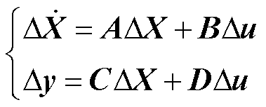
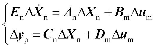
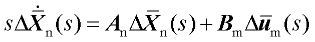
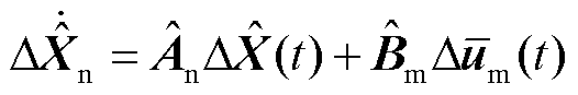
双馈风电机组由多台DFIG构成,其中每台DFIG的结构如图1所示,DFIG由感应发电机、传动轴系、转子侧换流器、网侧换流器、锁相环、直流母线电容和连接电感组成[37]。其线性化状态空间模型可表示为
(1)
式中, 为单台DFIG系统的状态矩阵;
 为系统的输入矩阵;
 为系统的输出矩阵;
 为系统的直接传递矩阵;
 为系统的状态变量,包括
 、
、 、
、 、
、 ~
~ 、
、 、
、 、
、 、
、 、
、 、
、 、
、 、
、 共18个状态变量,为风机的机械旋转角速度,为发电机的电角速度,
 为风力机传动轴扭转角度,~为PI控制器中积分项的输出,和
 分别为定子电流d、q轴分量,和分别为转子电流d、q轴分量,为直流母线电压,和分别为风机并网点的输出电流d、q轴分量,为锁相环的输出相位;
 为系统的输入向量,包括
 、
、 两个变量,分别为风机并网点电压的d、q轴分量;
 为系统的输出向量,包括、两个变量,分别为风机并网点输出电流的d、q轴分量。
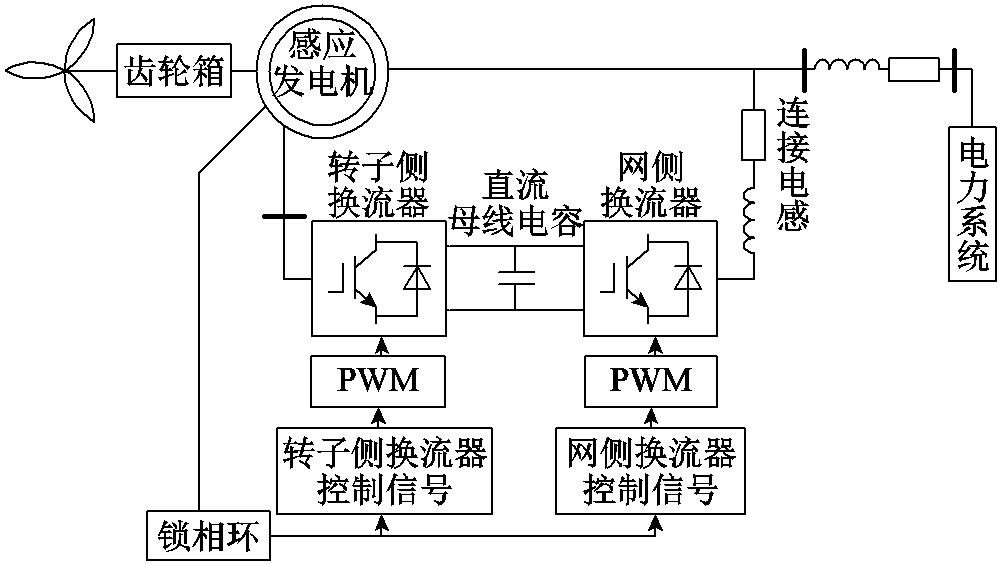
图1 单台DFIG结构示意图
Fig.1 Structure diagram of a single DFIG
并联双馈风电机组全阶模型则可依据式(1)表示为如式(2)所示形式[38]。
 (2)
(2)
式中, 、
、 、
、 、
、 、
、 、
、 分别为双馈风电机组的状态矩阵、输入矩阵、输出矩阵、直接传递矩阵、状态变量和相应阶数的单位对角矩阵;
 为双馈风电机组的输入向量,包含并网点电压d、q轴分量
 、
、 ;
; 为双馈风电机组的输出向量,包含并网点输出电流的d、q轴分量
 、
、 。
。
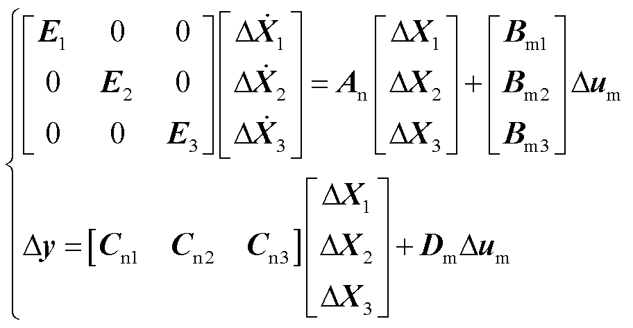
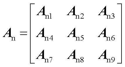
式(2)中所示的双馈风电机组全阶状态空间模型可以分解为含锁相环部分的解耦子系统和由其余部分组成的解耦主系统。解耦子系统中包含锁相环结构中含有的状态变量。解耦后,主系统的输出变为子系统的输入;子系统的输出变为主系统的输入。
首先将双馈风电机组中的状态变量重新排序,形成如式(3)所示的三部分向量。
 (3)
(3)
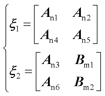
式中, 为解耦主系统中的状态变量;
 为解耦主系统的代数变量;
 则包含解耦子系统中所有的状态变量与代数变量。将式(3)代入式(2)中可得如式(4)和式(5)的双馈风电机组的表征形式。
 (4)
(4)
 (5)
(5)
式中, ~
~ 和
和 ~
~ 分别对应式(3)中的状态变量、和;对应系统的输入。
由式(4)可得双馈风电机组解耦主系统的表征形式为
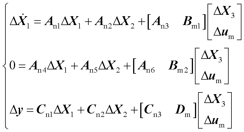 (6)
(6)
类似地,解耦子系统的表征形式可表示为
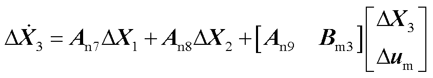 (7)
(7)
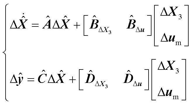
由式(6)和式(7)可得双馈风电机组解耦系统的状态空间模型表征为
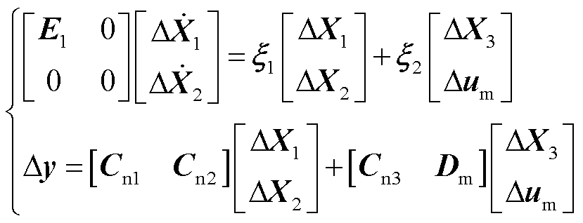 (8)
(8)
 (9)
(9)
给定一个稳定的状态空间系统,平衡截断方法可以生成一个稳定的降阶系统模型,并具有全频域内的误差界限[28]。
平衡截断方法主要由两个步骤组成:①通过求解Lyapunov方程计算系统的可控/可观格莱姆矩阵并对可控/可观格莱姆矩阵进行Choleski因子分解;②利用Choleski因子构造截断矩阵并进行系统降阶。
2.2.1 Lyapunov方程求解及Choleski因子分解
针对式(2)所示的双馈风电机组,其可控gramian矩阵 和可观gramian矩阵
 的求解需要通过求解如式(10)所示的Lyapunov方程实现。
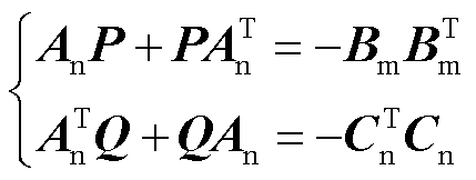 (10)
(10)
式(10)中两个方程互为对偶,求解过程类似。针对维数较高的大型系统的Lyapunov方程求解,其通常需要用到交替方向隐式迭代求解,目前较为常用的是稀疏低秩Choleski因子交替隐式迭代(Sparse Low Rank Choleski Factor-Alternating Direction Implicit method, SLRCF-ADI)。以可控矩阵 为例,SLRCF-ADI的求解原理是将式(10)所示的方程求解转换为迭代求解的形式。
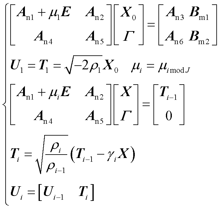
首先将系统中的迭代项 分解为如式(11)所示的Choleski因子形式,并按照如式(12)所示的迭代步骤进行迭代求解。
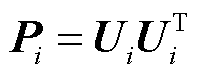 (11)
(11)
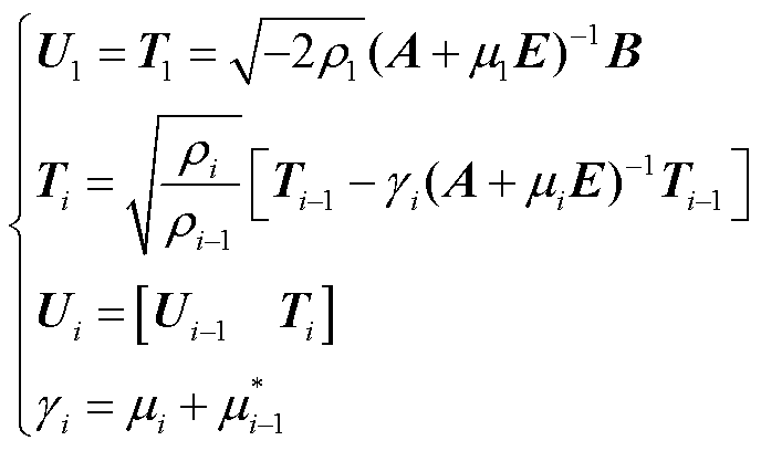 (12)
(12)
式中, 为ADI迭代参数μi的实部;
 为ADI迭代参数,
 为实部小于0的复数集合;
 。
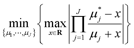
。 的选取满足如式(13)所示的极大极小问题[39]。
 (13)
(13)
针对计算量巨大的 ,结合已解耦的风电机组表征式(8)形成如式(14)所示的稀疏矩阵迭代形式,大幅度降低系统计算量。
 (14)
(14)
与式(11)~式(14)中以可控gramian矩阵为例通过SLRCF-ADI迭代求解出的Cholseki因子 类似,与对偶的gramian矩阵的Choleski因子同样可由SLRCF-ADI求解,并可表示为如式(15)的形式。
 (15)
(15)
2.2.2 截断矩阵构造与系统降阶
对可控可观矩阵Choleski因子的乘积进行Hankel奇异值分解,并可表示为
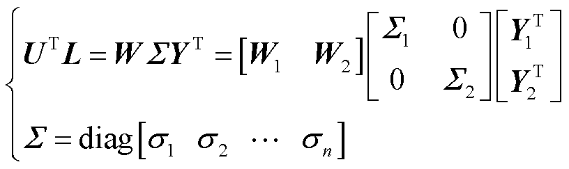 (16)
(16)
式中, 和
和 分别由矩阵
分别由矩阵 和矩阵
和矩阵 的前
的前 列组成;矩阵
 包含矩阵
包含矩阵 全部的Hankel奇异值
 ;分解后矩阵
 包含矩阵中的(
 )个最大的Hankel奇异值。
由此系统的截断矩阵可表示为[40]
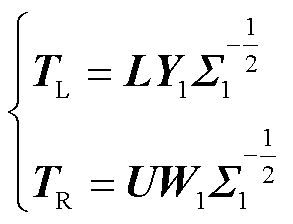 (17)
(17)
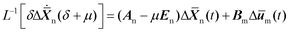
由于系统平衡截断降阶的前提假设是系统稳定,亦即系统状态矩阵为Hurwitz,对此本文在Laplace变换中引入正常数μ,即将Laplace变量s表示为s=δ+μ,其中δ亦为Laplace变量。在Laplace变换中应用新变量δ,并进行Laplace反变换可以得到调整后系统的状态矩阵为An-μE。此时,调整后的系统状态矩阵满足Hurwitz,可以用于系统平衡阶段降阶,降阶后的系统通过Laplace反变换可表示为
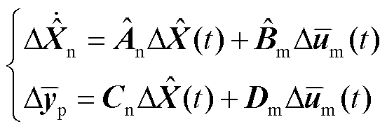 (18)
(18)
式中,各降阶矩阵和降阶状态变量可表示为
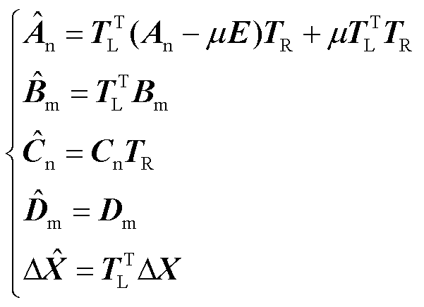 (19)
(19)
证明过程如下,对式(2)中的微分方程两侧同时取Laplace变换,可得
 (20)
(20)
将Laplace变量s替换为s=δ+μ后可得
 (21)
(21)
对式(21)两侧同时取Laplace反变换可得
 (22)
(22)
式中, 表示Laplace反变换。由于式(21)左侧的Laplace变量不统一,不能直接进行Laplace反变换。此时,经调整后式(22)的状态矩阵
 已满足Hurwitz,因此可以进行降阶处理。对式(21)两侧同时左乘截断矩阵
 可得
可得
 (23)
(23)
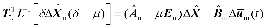
由于 ,式(23)可转换为
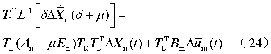
结合截断矩阵表征式(19),式(24)进而可以转换为
 (25)
(25)
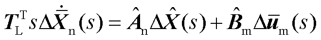
此时,对式(25)方程两侧进行Laplace变换,并将Laplace变量δ通过δ=s-μ替换回s,可得
 (26)
(26)
化简可得
 (27)
(27)
最后通过Laplace反变换可得
 (28)
(28)
针对系统进行Laplace变换及Laplace变量替换,在系统满足Hurwitz后进行降阶处理并反替换Laplace变量δ=s-μ,最后由Laplace反变换可以得到原系统的降阶模型,全过程中引入的正常数μ在变换中因消去而对后续处理过程没有任何影响,同时正常数μ使得变换中系统状态矩阵满足Hurwitz,消除了传统模型降阶技术系统稳定的前提假设。
解耦系统的降阶模型则可以表示为如式(29)所示的形式,同时降阶系统的稳定性在降阶过程中保持不变[41]。
 (29)
(29)
并联双馈风电机组最终的降阶模型可通过恢复解耦系统降阶模型中子系统保留的状态变量实现。由式(4)可得解耦主系统的代数变量为
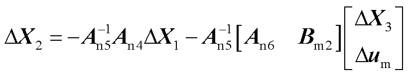 (30)
(30)
结合解耦子系统模型式(7)可得消去代数变量的解耦子系统模型为
 (31)
(31)
同时解耦主系统状态变量与降阶解耦系统的状态变量之间的关系可通过式(17)表示为
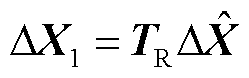 (32)
(32)
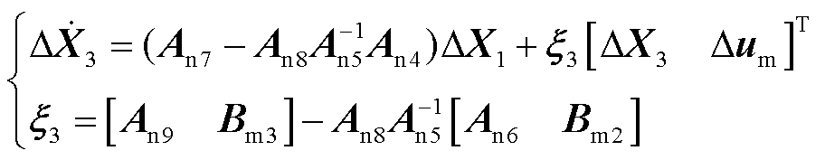
由式(31)和式(32)可得降阶解耦系统中保留下来的原解耦子系统的模型为
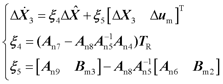 (33)
(33)
结合降阶解耦系统模型式(29)与保留的原解耦子系统式(33),可得双馈风电机组降阶系统模型为
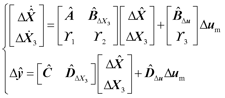 (34)
(34)
其中
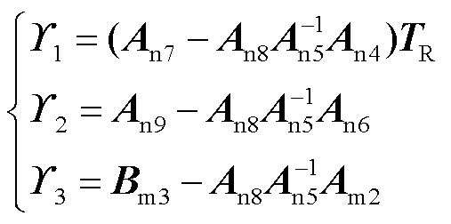 (35)
(35)
由于平衡截断降阶方法在系统降阶过程中只对原系统的状态变量及状态空间表达式中的状态矩阵、输入、输出矩阵进行降阶变化,并不影响系统的输入向量,因此针对保留在输入向量中的解耦子系统,降阶后的系统模型可以完整保留其对应的状态变量。
同时,由式(4)和式(32)可知,解耦子系统中包含子系统各控制器参数的状态矩阵 完整且仅存在于矩阵
 中,即降阶系统可完整保留解耦子系统的整体结构。此外,由式(32)可知,矩阵与矩阵对保留在中各控制器参数具有相同的偏导数,即
 ,因此基于闭环极点灵敏度的控制设计方法可以基于此得到应用。
由2.1节和2.2节中基于参数保留的平衡截断方法可知,保留锁相环完整结构的双馈风电机组降阶模型的构建首先需要对双馈风电机组的模型进行解耦,即将锁相环结构解耦为子系统;其次利用SLRCF-ADI求解Lyapunov方程计算双馈风电机组解耦系统的可控/可观gramian矩阵U和L,并对其进行Choleski因子分解;再次通过对Choleski因子的乘积进行Hankel奇异值分解,并截断较大奇异值对应的状态变量;然后利用分解因子矩阵构造截断矩阵并进行双馈风电机组解耦系统降阶;最后将降阶解耦系统中锁相环结构与降阶解耦主系统恢复耦合关系,得到保留完整锁相环结构的双馈风电机组降阶模型,具体算法见表1。
表1 保留锁相环的双馈风电机组模型降阶算法
Tab.1 Doubly-fed wind farm model order reduction algorithm with PLL retained
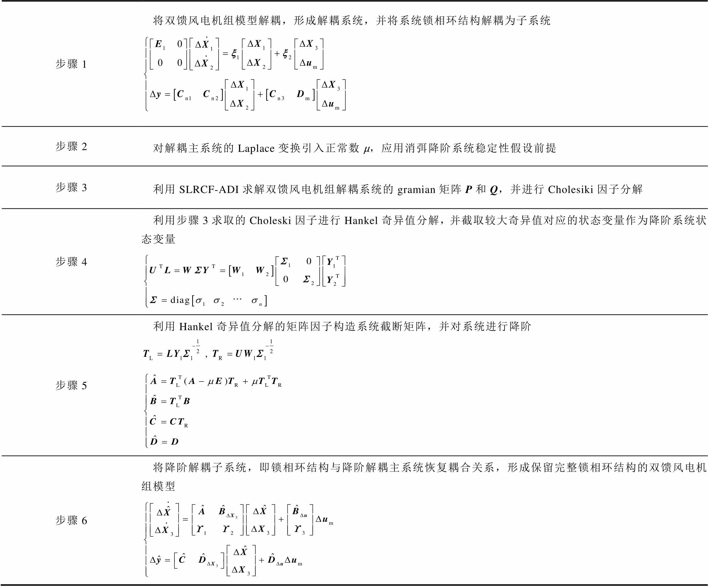
步骤1将双馈风电机组模型解耦,形成解耦系统,并将系统锁相环结构解耦为子系统 步骤2对解耦主系统的Laplace变换引入正常数μ,应用消弭降阶系统稳定性假设前提 步骤3利用SLRCF-ADI求解双馈风电机组解耦系统的gramian矩阵P和Q,并进行Cholesiki因子分解 步骤4利用步骤3求取的Choleski因子进行Hankel奇异值分解,并截取较大奇异值对应的状态变量作为降阶系统状态变量 步骤5利用Hankel奇异值分解的矩阵因子构造系统截断矩阵,并对系统进行降阶 步骤6将降阶解耦子系统,即锁相环结构与降阶解耦主系统恢复耦合关系,形成保留完整锁相环结构的双馈风电机组模型
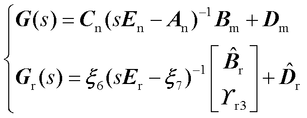
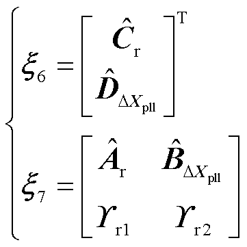
根据前文的论述,将锁相环的完整结构移到解耦子系统中,并应用2.2节所论述的平衡截断方法,则保留锁相环结构的双馈风电机组降阶模型为
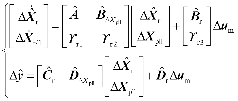 (36)
(36)
式中,锁相环的结构选取如图2所示,则 可表示为
可表示为 ,
, 为锁相环中另一积分器的输出;
 为双馈风电机组解耦主系统的降阶状态变量;
 、
、 、
、 、
、 组成了降阶系统的状态矩阵;
 、
、 组成了降阶系统的输入矩阵;
 、
、 组成了降阶系统的输出矩阵;
 为降阶系统的直接传递矩阵。
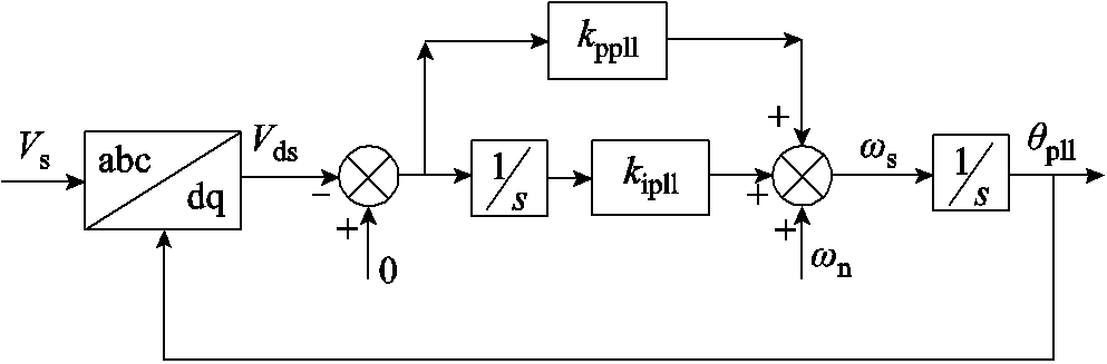
图2 DFIG锁相环结构
Fig.2 DFIG phase-locked loop structure
由2.2节中基于参数保留的平衡截断方法可知解耦系统的降阶模型中解耦子系统的结构得到完全的保留。保留了锁相环的降阶系统与全阶系统在频域响应上满足如式(37)所示的全局误差。
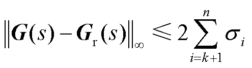 (37)
(37)
式中, 和
和 分别为双馈风电机组全阶系统和降阶系统的传递函数,其与系统状态空间模型的关系为
 (38)
(38)
 (39)
(39)
并联双馈风电机组为多输入多输出系统,其传递函数为矩阵形式,矩阵中每个元素 都为标量函数,且代表系统第j个输入对第i个输出的传递关系,主对角线上的元素代表对应输出与输入之间的关系,即
 ;非对角线元素则代表非对应输出与输入之间的耦合关系,即
 。
。
全阶系统的输入和输出可表示为
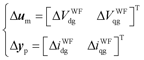 (40)
(40)
因此其传递函数矩阵即为双馈风电机组的导纳矩阵,可表示为
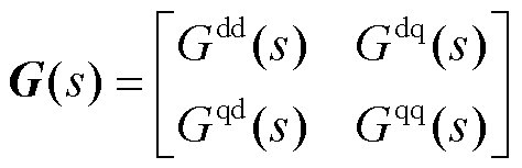 (41)
(41)
式中, 、
、 、
、 、
、 分别为电压d轴分量与输出电流d轴分量、电压q轴分量与输出电流d轴分量、电压d轴分量与输出电流q轴分量、电压q轴分量与输出电流q轴分量的传递关系。
降阶系统的传递函数矩阵与全阶系统类似,可表示为
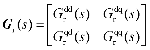 (42)
(42)
为验证保留锁相环的双馈风电机组降阶系统的响应特性,本文通过第2节中提出的基于平衡截断的锁相环结构保留的降阶方法,针对并联风电场系统,在全频域内对所提出的保留锁相环完整结构的并联风电场降阶系统与并联风电场全阶系统传递函数的响应特性进行对比,并展示了设定工况及其小扰动下的响应误差。
实验中以20台DFIG组成的并联双馈风电机组为例,其全阶模型包含360个状态变量,通过第3节中论述的双馈风电机组锁相环保留的降阶之后,降阶模型包含142个状态变量,双馈风电机组运行工况设定风速为7.5 m/s,降价模型和全阶模型对比见表2。
表2 降阶模型和全阶模型对比
Tab.2 Performance comparison between DPMA and DFT algorithm
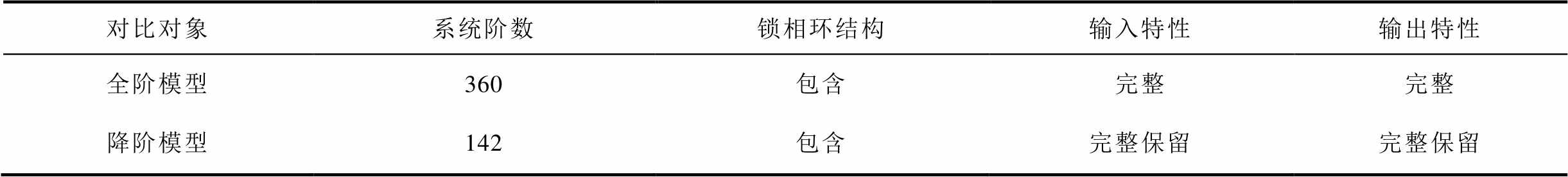
对比对象系统阶数锁相环结构输入特性输出特性 全阶模型360包含完整完整 降阶模型142包含完整保留完整保留
双馈风电机组全阶/降阶模型中,系统输入为并网点电压的dq分量,输出为并网点输出电流的dq分量。在7.5 m/s的工况下,降阶系统与全阶系统的时域动态响应曲线及对比如图3和图4所示。
图3中为全阶系统和降阶系统并网点A相电压波形,并联DFIG机组的降阶系统在并网点输入电压的响应波形上与全阶系统基本保持一致。风电场降阶系统的输入电压特性保持不变。
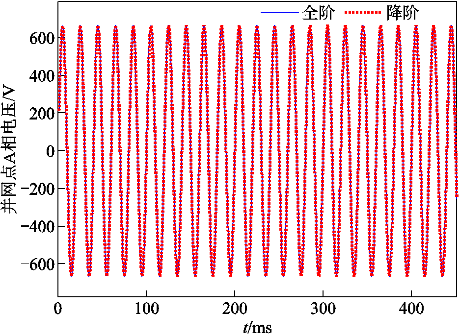
图3 降阶/全阶系统的时域电压响应曲线及对比
Fig.3 Time domain voltage response curves and comparison of reduced order/full order systems
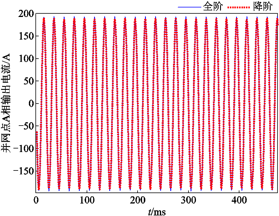
图4 降阶/全阶系统的时域电流响应曲线及对比
Fig.4 Time domain current response curves and comparison of reduced order/full order systems
图4中为全阶系统和降阶系统并网点A相输出电流波形,并联DFIG机组的降阶系统在并网点输出电流的响应波形上与全阶系统基本保持一致。风电场降阶系统的输出电流特性保持不变。
由于降阶模型不改变系统的输入和输出变量,同时由模型可知表征其输入输出特性的传递函数矩阵即为双馈风电机组的导纳矩阵,在7.5 m/s的工况下,其传递函数矩阵中各元素在全频域下的响应曲线及全阶系统/降阶系统对应误差如图5~图8所示。
图5和图6分别为双馈风电机组输入(并网点电压dq分量)和系统并网点输出电流d轴分量的传递关系及两系统误差的幅频特性曲线;图7和图8则为输入和系统并网点输出电流q轴分量的传递关系和两系统误差的幅频特性曲线。图5~图8中上半图表示系统传递函数,下半图表示两系统误差。
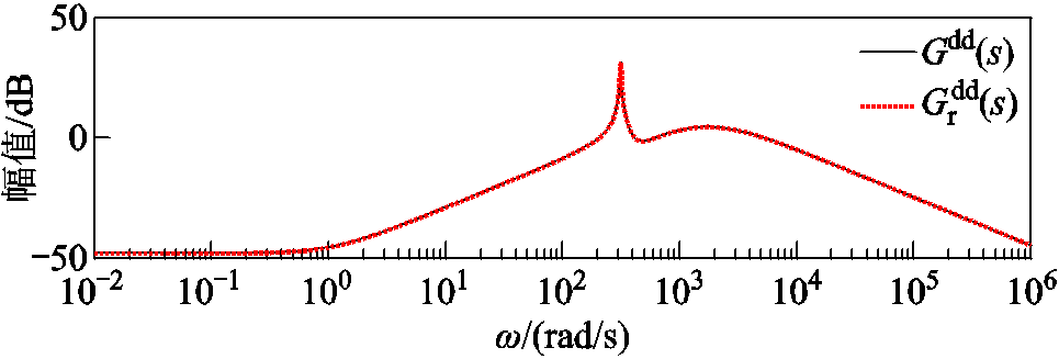
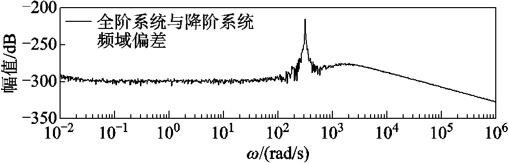
图5 降阶/全阶系统 的全频域响应曲线及误差
Fig.5 Full frequency response curve and error of between reduced and full order system
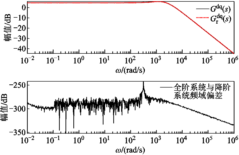
图6 降阶/全阶系统 的全频域响应曲线及误差
Fig.6 Full frequency response curve and error of between reduced and full order system

图7 降阶/全阶系统 的全频域响应曲线及误差
Fig.7 Full frequency response curve and error of between reduced and full order system
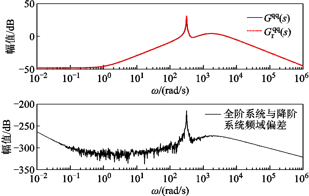
图8 降阶/全阶系统 的全频域响应曲线及误差
Fig.8 Full frequency response curve and error of between reduced and full order system
图中降阶系统在全频域内的幅频特性响应曲线与全阶系统在7.5 m/s的工况下保持一致,同时两者的偏差远小于 。降阶模型可以在全频域内分别匹配全阶模型中系统输入和系统并网点输出电流d轴分量传递关系和,以及输入和系统并网点输出电流q轴分量传递关系和的幅频特性关系。
图9和图10分别为双馈风电机组输入(并网点电压dq分量)和系统并网点输出电流d轴分量的传递关系及两系统误差的相频特性曲线;图11和图12分别为双馈风电机组输入和系统并网点输出电流q轴分量的传递关系及两系统误差的相频特性曲线。图中降阶系统在全频域内的相频特性曲线与全阶系统在7.5 的工况下保持一致,同时两者的偏差基本保持在0。降阶模型可以分别匹配全阶模型中系统输入和系统并网点输出电流d轴分量传递关系和,以及输入和系统并网点输出电流q轴分量传递关系和的相频特性关系。
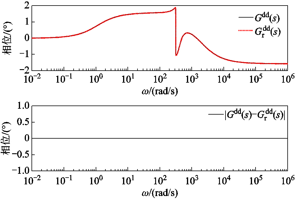
图9 降阶/全阶系统的全频域相频曲线及误差
Fig.9 Phase frequency curves and errors of in the full frequency domain of reduced order/full order systems
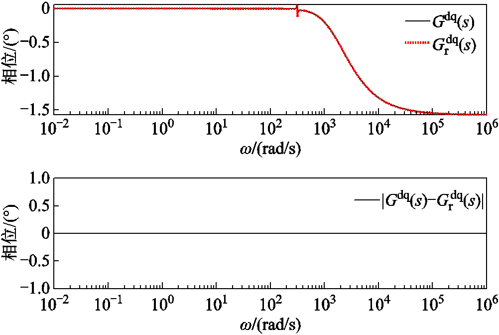
图10 降阶/全阶系统的全频域相频曲线及误差
Fig.10 Phase frequency curves and errors of in the full frequency domain of reduced order/full order systems
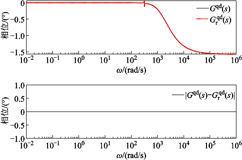
图11 降阶/全阶系统的全频域相频曲线及误差
Fig.11 Phase frequency curves and errors of in the full frequency domain of reduced order/full order systems
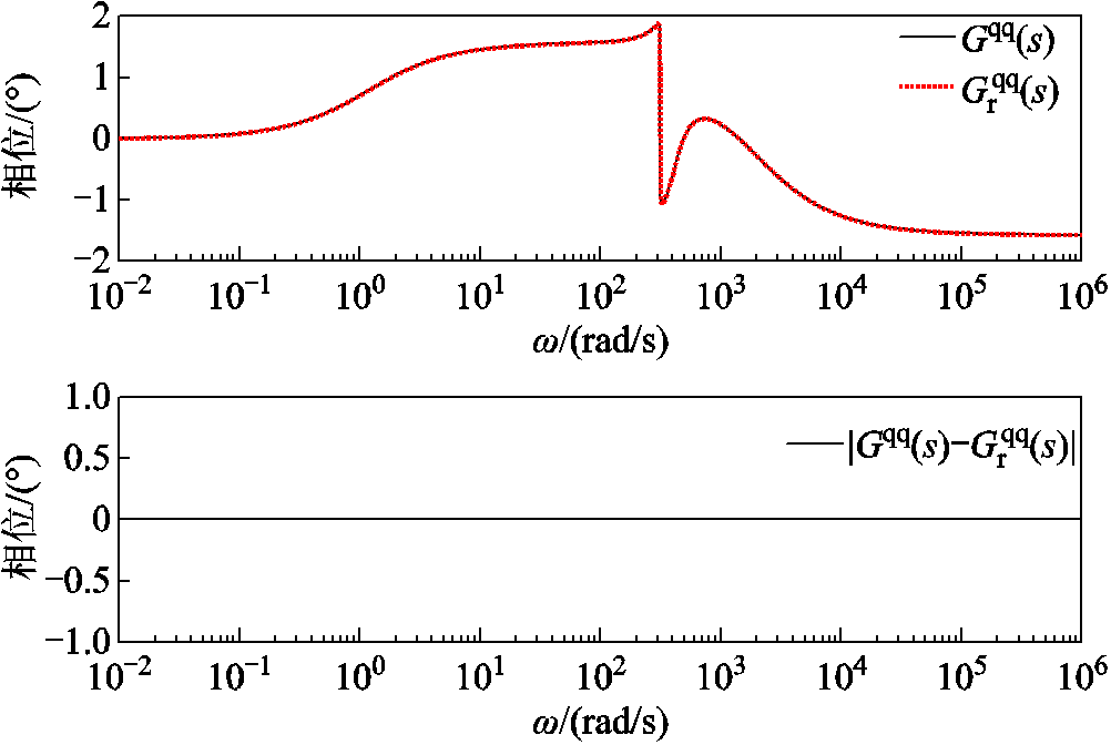
图12 降阶/全阶系统的全频域相频曲线及误差
Fig.12 Phase frequency curves and errors of in the full frequency domain of reduced order/full order systems
图13所示为双馈风电机组降阶模型与全阶模型的时域并网点输出电流误差。图13中双馈风电机组的两种模型对系统并网点输出电流 和
和 输出误差的数量级均在
 。降阶系统模型的输出
 可以较好地匹配全阶系统模型的输出。
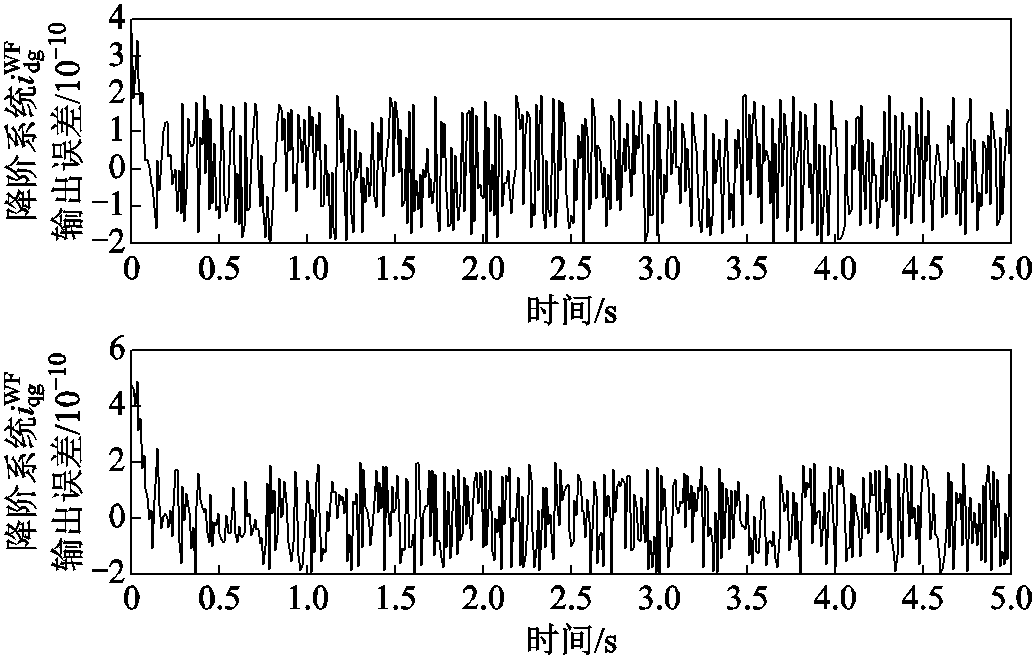
图13 降阶/全阶系统时域输出误差
Fig.13 Reduced/full order system time domain output error
小扰动下,本文分别展示了保留锁相环完整结构的并联风电场降阶系统与全阶系统的传递函数矩阵主对角线元素的幅频特性曲线,即降阶/全阶系统和。
风速在7.5的设定工况时,外界产生风速的小扰动后,基于锁相环保留的并联风电场降阶系统和全阶系统的传递函数主对角线元素全频域幅频特性曲线对比如图14~图17所示。由于非主对角线元素的对比与主对角线元素类似,文章仅展示主对角线元素的对比。从图14~图17中可以看出,在外界风速的小扰动情况下,降阶系统与全阶系统的幅频特性曲线完全贴合,且与设定工况基本保持一致,不会产生较大偏差;同时也可以得出在小扰动的风速下,系统的导纳矩阵基本保持不变,亦即阻抗特性保持不变。本文提出的基于锁相环完整结构保留的降阶方法能够保留降阶系统与全阶系统的输入输出特性,解决了并联风电场降阶系统因锁相环结构不完整导致特定频段内响应曲线难以贴合全阶系统的问题。
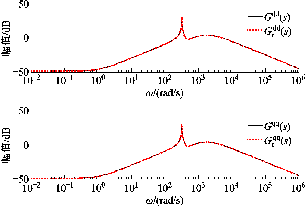
图14 降阶/全阶系统的和在风速为6.5 m/s下的全频域幅频曲线
Fig.14 Amplitude frequency curves of and in the full frequency domain of reduced order/full order systems under wind speed of 6.5 m/s
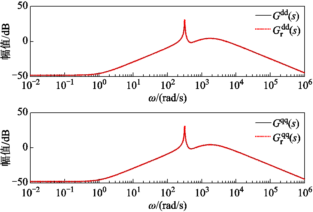
图15 降阶/全阶系统的和在风速为7 m/s下的全频域幅频曲线
Fig.15 Amplitude frequency curves of and in the full frequency domain of reduced order/full order systems under wind speed of 7 m/s
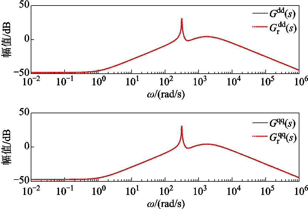
图16 降阶/全阶系统的和在风速为8 m/s下的全频域幅频曲线
Fig.16 Amplitude frequency curves of and in the full frequency domain of reduced order/full order systems under wind speed of 8 m/s
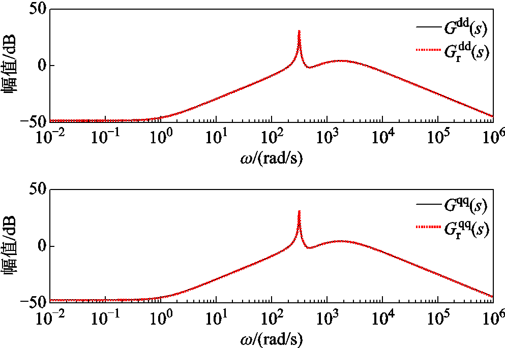
图17 降阶/全阶系统的和在风速为8.5 m/s下的全频域幅频曲线
Fig.17 Amplitude frequency curves of and in the full frequency domain of reduced order/full order systems under wind speed of 8.5 m/s
综上所述,并联双馈风电机组降阶模型的传递函数矩阵及其各元素均可以在全频域内匹配全阶系统传递函数矩阵中对应元素的幅相频率特性,保留锁相环完整结构的双馈风电机组降阶模型解决了特定频段内响应曲线无法贴合全阶系统的问题。同时由于系统传递函数相同,亦即系统源侧的导纳/阻抗矩阵保持不变,阻抗稳定性分析同样可以适用于降阶模型。
随着大规模风电机组的快速发展和广泛普及,模型降阶方法已成为模型仿真中不可或缺的一环。传统的基于平衡截断的并联双馈风电机组模型降阶方法虽然能够保证降阶模型的频域响应曲线在全频域内较好地贴合全阶系统,但在特定频段内因缺少锁相环完整结构,仍与全阶系统响应曲线有较大偏差。对此,本文提出了一种基于平衡截断并保留锁相环完整结构的并联双馈风电机组模型,使得降阶系统频率响应曲线能够在全频域内完全贴合全阶系统,同时改进了平衡截断降阶方法,消除了需要系统稳定的前提假设,为分析锁相环诱发的同步振荡和同步失准问题提供了精准的模型。
参考文献
[1] 习近平主持召开中央全面深化改革委员会第二次会议强调建设更高水平开放型经济新体制推动能耗双控逐步转向碳排放双控[N]. 人民日报, 2023-07-12(1).
[2] 国家能源局. 国家能源局发布2023年全国电力工业统计数据[J]. 电力科技与环保, 2024, 40(1): 95.
[3] 王也, 徐茂达, 郝文波, 等. 双馈感应风机控制环节对电力系统机电小干扰稳定的影响分析[J]. 电气技术, 2019, 20(9): 31-38.
Wang Ye, Xu Maoda, Hao Wenbo, et al. Analysis of electromechanical small-signal stability of power system as affected by control-links of doubly fed induction generator[J]. Electrical Engineering, 2019, 20(9): 31-38.
[4] Wang Rui, Yu Xiaohan, Sun Qiuye, et al. The integrated reference region analysis for parallel DFIGs’ interfacing inductors[J]. IEEE Transactions on Power Electronics, 2024, 39(6): 7632-7642.
[5] 季一宁, 王海风. 包含串补的并网直驱风电场振荡稳定性及可行域分析[J]. 电工技术学报, 2024, 39(3): 686-698.
Ji Yining, Wang Haifeng. Analysis of oscillation stability and feasible region of parameters in grid-connected direct-drive wind farm with series compensation[J]. Transactions of China Electrotechnical Society, 2024, 39(3): 686-698.
[6] 孙秋野, 于潇寒, 王靖傲. “双高”配电系统的挑战与应对措施探讨[J]. 中国电机工程学报, 2024, 44(18): 7115-7136.
Sun Qiuye, Yu Xiaohan, Wang Jing’ao. Discussion on challenges and countermeasures of “double high” power distribution system[J]. Proceedings of the CSEE, 2024, 44(18): 7115-7136.
[7] Wang Rui, Sun Qiuye, Tu Pengfei, et al. Reduced-order aggregate model for large-scale converters with inhomogeneous initial conditions in DC microgrids [J]. IEEE Transactions on Energy Conversion, 2021, 36(3): 2473-2484.
[8] de Oliveira S E M, de Queiroz J F. Modal dynamic equivalent for electric power systems. I. theory[J]. IEEE Transactions on Power Systems, 1988, 3(4): 1723-1730.
[9] Trudnowski D I. Order reduction of large-scale linear oscillatory system models[J]. IEEE Transactions on Power Systems, 1994, 9(1): 451-458.
[10] 高本锋, 邓鹏程, 孙大卫, 等. 基于匹配控制的构网型直驱风电场次同步振荡机理与特性研究[J]. 电工技术学报, 2024, 39(9): 2755-2770.
Gao Benfeng, Deng Pengcheng, Sun Dawei, et al. Mechanism and characteristics of subsynchronous oscillation of grid-forming direct-drive wind farm based on matching control[J]. Transactions of China Electrotechnical Society, 2024, 39(9): 2755-2770.
[11] Li P, Zhang B H, Shu J, et al. Research on order reduction of power system modeling for dynamic voltage stability analysis[C]//IEEE PES T&D 2010, New Orleans, LA, USA, 2010: 1-5.
[12] Rasheduzzaman M, Mueller J A, Kimball J W. Reduced-order small-signal model of microgrid systems[J]. IEEE Transactions on Sustainable Energy, 2015, 6(4): 1292-1305.
[13] 高本锋, 王刚, 邵冰冰, 等. 基于主导度分析的直驱风电机组系统奇异摄动降阶方法[J]. 中国电机工程学报, 2022, 42(7): 2449-2462.
Gao Benfeng, Wang Gang, Shao Bingbing, et al. Singular perturbation approximation method based on the dominant degree analysis for direct drive wind farm[J]. Proceedings of the CSEE. 2022, 42(7): 2449-2461
[14] Zhao Zhuoli, Wu Junhua, Luo Xi, et al. Reduced-order model for wind-solar multi-microgrids considering time-scale coupling[J]. IEEE Transactions on Power Systems, 2024, 39(1): 2052-2065.
[15] 王彤, 李永达, 高洁, 等. 基于受扰轨迹空间解耦的直驱风电机组非线性动态降阶方法[J]. 中国电机工程学报, 2023, 43(21): 8206-8217.
Wang Tong, Li Yongda, Gao Jie, et al. Nonlinear dynamic order reduction method of direct driven wind turbine based on disturbed trajectory space decoupling [J]. Proceedings of the CSEE, 2023, 43(21): 8206-8217.
[16] Ma Jing, Song Zhanxiang, Zhang Yongxin, et al. Model order reduction analysis of DFIG integration on the power system small-signal stability considering thevirtual inertia control[J]. IET Generation, Transmission & Distribution, 2017, 11(16): 4087-4095.
[17] Chaniotis D, Pai M A. Model reduction in power systems using Krylov subspace methods[C]//IEEE Power Engineering Society General Meeting, 2005, San Francisco, CA, USA, 2005: 1412.
[18] Wang Chengshan, Yu Hao, Li Peng, et al. Krylov subspace based model reduction method for transient simulation of active distribution grid[C]//2013 IEEE Power & Energy Society General Meeting, Vancouver, BC, Canada, 2013: 1-5.
[19] Sun Yingyun, Dong Jingyuan, Pu Tianjiao, et al. Reduction of power system dynamic model using Krylov subspace method[C]//2014 International Conference on Power System Technology, Chengdu, China, 2014: 343-348.
[20] Antoulas A C. Approximation of Large-Scale Dynamical Systems[M]. Philadelphia: Society for Industrial and Applied Mathematics, 2005.
[21] Ali H R, Kunjumuhammed L P, Pal B C, et al. Model order reduction of wind farms: linear approach [J]. IEEE Transactions on Sustainable Energy, 2019, 10(3): 1194-1205.
[22] Magruder C, Beattie C, Gugercin S. Rational Krylov methods for optimal ℒ2 model reduction[C]//49th IEEE Conference on Decision and Control (CDC), Georgia, 2010: 6797-6802.
[23] Yogarathinam A, Kaur J, Chaudhuri N R. A new H-IRKA approach for model reduction with explicit modal preservation: application on grids with renewable penetration[J]. IEEE Transactions on Control Systems Technology, 2019, 27(2): 880-888.
[24] Ghosh S, Isbeih Y J, El Moursi M S, et al. Cross-gramian model reduction approach for tuning power system stabilizers in large power networks[J]. IEEE Transactions on Power Systems, 2020, 35(3): 1911-1922.
[25] Qin Boyu, Sun Haoyuan, Ma Jin, et al. Robust {Hınfty} control of doubly fed wind generator via state-dependent Riccati equation technique[J]. IEEE Transactions on Power Systems, 2019, 34(3): 2390-2400.
[26] Stykel T. Gramian-based model reduction for descriptor systems[J]. Mathematics of Control, Signals and Systems, 2004, 16(4): 297-319.
[27] 赵洪山, 兰晓明, 王颖, 等. 基于平衡Gramian的电力系统电压预测控制研究[J]. 中国电机工程学报, 2016, 36(22): 6038-6048.
Zhao Hongshan, Lan Xiaoming, Wang Ying, et al. Research on voltage prediction control of power system based on balanced gramian[J]. Proceedings of the CSEE, 2016, 36(22): 6038-6048.
[28] Penzl T. A cyclic low-rank Smith method for large sparse Lyapunov equations[J]. SIAM Journal on Scientific Computing, 1999, 21(4): 1401-1418.
[29] Fernando K, Nicholson H. On the structure of balanced and other principal representations of SISO systems[J]. IEEE Transactions on Automatic Control, 1983, 28(2): 228-231.
[30] 张喆, 赵洪山, 李志为, 等. 平衡格莱姆方法在电力系统线性模型降阶中的应用[J]. 电工技术学报, 2013, 28(6): 201-207.
Zhang Zhe, Zhao Hongshan, Li Zhiwei, et al. Power system linear model reduction based on the balanced gramian method[J]. Transactions of China Electro-technical Society, 2013, 28(6): 201-207.
[31] Liu Ju, Yao Wei, Wen Jinyu, et al. Impact of power grid strength and PLL parameters on stability of grid-connected DFIG wind farm[J]. IEEE Transactions on Sustainable Energy, 2020, 11(1): 545-557.
[32] UK Energy Research Centre. What happened on august the 9th–the investigations[EB/OL]. (2020-01-15)[2024-04-16]. https://ukerc.ac.uk/news/august-9-investigations/.
[33] UK Goverment. Business Secretary sets out scope of investigation into power cuts[EB/OL]. (2019-08-14) [2020-04-16]. https://www.gov.uk/government/news/ business-secretary-sets-out-scope-of-investigation-into-power-cuts.
[34] Buragohain U, Senroy N. Reduced order DFIG models for PLL-based grid synchronization stability assessment [J]. IEEE Transactions on Power Systems, 2023, 38(5): 4628-4639.
[35] Kaur J, Chaudhuri N R. MIMO model reduction of modern power grids with wind generation: Some new findings[C]//2017 IEEE Power & Energy Society General Meeting, Chicago, IL, USA, 2017: 1-5.
[36] Morovati S, Zhang Yichen, Djouadi S M, et al. Robust output feedback control design for inertia emulation by wind turbine generators[J]. IEEE Transactions on Power Systems, 2021, 36(6): 5056-5067.
[37] Hu Jiabing, Wang Bo, Wang Weisheng, et al. Small signal dynamics of DFIG-based wind turbines during riding through symmetrical faults in weak AC grid[J]. IEEE Transactions on Energy Conversion, 2017, 32(2): 720-730.
[38] 赵洪山, 宋国维, 江全元. 利用平衡理论进行电力系统模型降阶[J]. 电工技术学报, 2010, 25(2): 127-133.
Zhao Hongshan, Song Guowei, Jiang Quanyuan. Reduction of power system model using balanced realization method[J]. Transactions of China Electro-technical Society, 2010, 25(2): 127-133.
[39] Li J R, White J. Low rank solution of Lyapunov equations[J]. SIAM Journal on Matrix Analysis and Applications, 2002, 24(1): 260-280.
[40] Simoncini V. Computational methods for linear matrix equations[J]. SIAM Review, 2016, 58(3): 377-441.
[41] Glover K. All optimal Hankel-norm approximations of linear multivariable systems and their L∞ error bounds[J]. International Journal of Control, 1984, 39(6): 1115-1193.
Abstract Phase-locked loop (PLL) has gradually become an important factor that causes low frequency and sub-/super-synchronous oscillation and synchronous misalignment of doubly-fed wind turbines (DFWTs). Many time-domain state-space models have been studied for the wide band oscillation of DFWTs caused by the mismatch of the PLL. However, these models are often difficult to analyze for their high order. At the same time, the method of reduced order model analysis is unable to analyze the mechanism of the instability caused by the PLL, as the specific structure can not be retained at the present stage. Therefore, in order to retain the advantages of the state space analysis method with the discrimination of instable characteristic root and the advantages of reduced order model with small amount and high computation efficiency, a method to construct a reduced-order model for DFWTs with complete structure preservation of PLL based on balanced truncation is proposed.
Firstly, the full-order small signal model of parallel DFWTs is established in the form of state space presentation. Secondly, the PLL structure is decoupled from the system and the system is separated into decoupled subsystem (including PLL) and decoupled main system. The general idea is to reduce the order of the decoupled main system without PLL, and then integrate the model of the reduced order model of decoupled main system with the PLL structure to form a reduced order model with the PLL. Then, the state variables contained in the PLL are retained in the decoupled subsystem. Thus, an improved balanced truncation is applied to the decoupled main system. In this paper, the traditional balanced truncation based model order reduction method is improved. The prerequisite condition that the state matrix of the model to be order-reduced must be Hurwitz is improved, so that the balanced truncation based model order reduction can be carried out for any unstable state matrix. In this paper, a positive constant is introduced into the Laplace transform to form two Laplace variables. By applying the new variable Laplace variable in Laplace transform and Laplace inverse transform, the state matrix of the adjusted system can be kept Hurwitz. At this time, the adjusted system state matrix satisfies Hurwitz and can be used for the balanced truncated based model order reduction of the system. The reduced order model of the original system can be obtained by Laplace inverse transformation. The positive constant introduced in the whole process is eliminated in the transformation, which has no effect on the subsequent processing. The improved balanced truncation eliminates the premise assumption of system stability in the traditional model reduction technology. Finally, the decoupled subsystem and the decoupled main system are combined, and the complete structure of PLL is preserved. In this paper, a method of complete PLL structure preserved model order reduction based on balanced truncation is given, and a set of pseudo code of model order reduction with PLL structure preserved is given which can be directly used for other parallel wind farms. In this paper, 20 wind turbines with DFWTs in parallel are taken as an example to verify the effectiveness of the proposed PLL complete structure preservation model order reduction method. The time-domain output errors between the reduced-order model and the full-order model are demonstrated. In order to demonstrate the response characteristics of the reduced order model of DFWTs with complete PLL structure preserved, the amplitude-frequency/phase-frequency response curves of each element in the transfer function matrix of the reduced order model and the full-order model are presented respectively in the full frequency domain. In addition, the amplitude-frequency characteristic curves of the main diagonal elements in the transfer function matrix of the reduced order model are shown in the full frequency domain under the presence of small wind velocity perturbations. The dynamic effectiveness of the proposed PLL preserved model order reduction method based on balanced truncation is demonstrated.
Keywords:Wind turbines, phase-locked loop, small-signal stability, reduced order model, balanced truncation
于潇寒 男,2001年生,博士研究生,研究方向为新型电力系统的稳定分析与致稳控制。
E-mail:13840165130@163.com
王 睿 男,1993年生,副教授,博士生导师,研究方向为风光储集成化微电网的稳定分析与运行控制。
E-mail:wangrui@ise.neu.edu.cn(通信作者)
中图分类号:TM712
DOI: 10.19595/j.cnki.1000-6753.tces.242362
国家自然科学基金(52307194, 5247072151)和国家重点研发计划(2023YFF0615000)资助项目。
收稿日期 2024-12-30
改稿日期 2025-03-10
(编辑 赫 蕾)