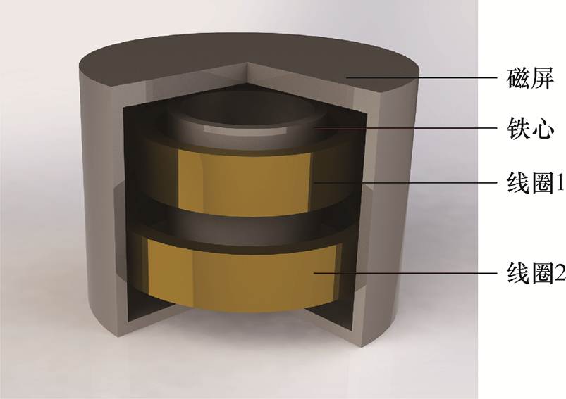
图1 带磁屏的圆筒铁心线圈三维模型
Fig.1 3D model of tubular iron-core coils with magnetic shield
摘要 该文运用增强型截断域本征函数展开法(ETREE)提出磁屏圆筒铁心线圈电感的计算公式。在该模型中,铁心磁导率为有限值,而磁屏磁导率可以是有限值,也可以是无穷大。归一化数值本征函数的运用,使得分析过程大为简化。所得的电感计算公式以有限元仿真进行了验证。数值计算结果表明,该文提出的计算公式与有限元仿真对比,其结果误差不超过0.5%,同时具有令人满意的计算效率。
关键词:磁屏 铁心线圈电感 增强型截断域本征函数展开法 电感计算
线圈电感的计算对多种电气应用设计十分重要,例如,电力滤波器[1-2]、电抗器[3]、无线能量传输系统[4-7]及涡流检测[8]。在高电压、大功率的应用场合(如功率因数调节、短路电流限制等),为了减小电抗线圈尺寸,往往采用铁心线圈结构。在这类线圈结构的设计分析中,需要使用快速准确的电感计算公式。对于铁心线圈电感计算,已有一些文献进行了讨论。在早期文献[9-10]中,H. Buchholz将铁心线圈简化为二维问题,并假设铁心磁导率为无穷大,采用复变函数共形映射技术与Jacobi椭圆函数给出了薄壁线圈的自感公式。J. Timmerberg在文献[11]中以截断域本征函数展开(Truncated Region Eigenfunction Expansion, TREE)给出了单端无穷长Ⅰ型铁心线圈的电感计算公式,这是此法首次用于铁心线圈的磁场分析。与传统的积分方法相比[12],TREE法将线圈电感计算由积分变为级数,在显著提高计算效率的同时,所得结果还能保持足够精度。后续以TREE法分析铁心线圈自感或互感的工作还见于文献[13-15]中。在文献[13]中,T. Lubin等以级数解给出了磁导率为无穷大的Ⅰ型铁心线圈的自感,但其推导中并未采用TREE法的矩阵形式,因此步骤较繁琐;在文献[14]中,Lu Yi等给出了磁导率为有限值的Ⅰ型铁心线圈自感的TREE解,但其对线圈源以Dirac-d函数进行处理,最后的表达式较复杂。在文献[15]中,Luo Yao对两个同轴的Ⅰ型铁心线圈给出了互感TREE解,并以本征函数展开线圈截面电流密度来处理Poisson方程,使得TREE表达式得到简化。
在实际应用中,为了减小高强度磁场对周围环境的影响[16-19]以及降低其对人体健康的潜在危害,通常需要将线圈置于屏蔽结构之内[20-21]。对于中低频磁场的屏蔽,一般运用高磁导率材料制成屏蔽壳(磁屏)。本文将分析带有磁屏的圆筒铁心线圈的磁场与电感。所谓圆筒铁心,是一个中空的Ⅰ型铁心,呈圆管状。与传统Ⅰ型铁心相比,圆筒铁心的质量更小,更节省铁磁材料,且管型结构有助于铁心的散热。
本文在分析中分别考虑了磁屏磁导率无穷大与磁屏磁导率有限的两种情况。传统TREE技术,原则上可以分析该模型,但处理多子域时将引入复杂的显式本征函数。例如,对磁屏磁导率有限的模型,采用r截断时将产生包含5个子域的复杂区域,其显式本征函数将含有大量Bessel函数。Bessel函数虽然可在许多数值软件中直接计算,但大量Bessel函数的使用仍会导致计算效率的降低。另一方面,传统TREE中的本征值以Newton法或Cauchy围道积分法计算[22],这两种方法的效率均不高,如果将这部分耗时计算在内,则TREE总耗时与纯数值法(如有限元法)相比没有优势。当需要进行优化计算时,铁心或磁屏蔽壳几何尺寸、磁导率的变化,都将导致本征值需要重新求解,这就使得传统TREE实际上不能很好地胜任需要多次求解本征值的应用场景。
因此,本文采用近年来提出的增强型截断域本征函数展开法(Enhanced TREE, ETREE)[23-25]。该方法以Sturm-Liouville方程处理多子域本征函数与本征值,并以一维高阶有限元基函数离散化Sturm- Liouville方程,由此可同时解得全部所需本征值。进一步地,多子域本征函数以归一化本征向量插值得到,这一过程可使TREE的分析过程大幅简化。由于ETREE计算本征值与本征函数的效率非常高,使得此法效率(包含求解本征值与本征函数的时间)相比于有限元仿真具有显著优势,并且能够胜任需要多次进行本征值求解的优化或逆问题计算场合。值得一提的是,ETREE的应用前提是相关边值问题可在直角坐标、圆柱坐标或其他常见坐标系中分离变量,因此其运用范围受到限制;但由于铁心圆柱线圈相关问题通常具有较规整的几何结构,运用此法进行分析是较为合适的。
本文详述了ETREE的分析过程,并在数值验证部分将ETREE结果与有限元软件结果进行了对比计算。结果表明,本文提出的计算公式具有很高的运算效率,同时计算精度也令人满意。
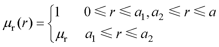
首先考虑磁屏磁导率无穷大的圆筒铁心线圈磁场与电感计算问题。带磁屏的圆筒铁心线圈三维模型如图1所示。考虑到模型的轴对称性,磁屏磁导率无穷大的圆筒铁心线圈截面示意图如图2所示。将其在图2所示的柱坐标中进行分析。对于磁导率无穷大的磁屏,无需考虑磁屏厚度,整个求解域被限制于磁屏内表面所界定的空间,即0≤r≤a, -b≤z≤b。图2中,矩形阴影区域为圆筒形铁心截面,其相对磁导率表示为mr;方形区域为两个圆柱线圈的截面,其电流密度分别表示为J1和J2,且该数值为常数。
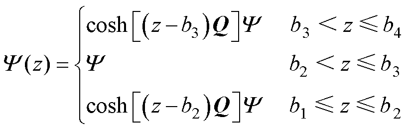
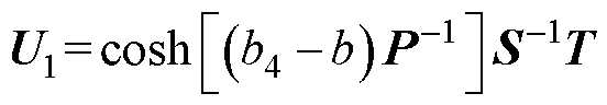
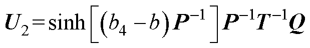
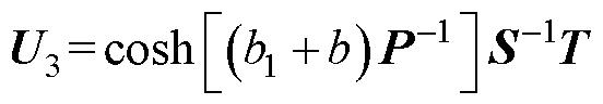
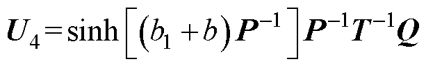
在计算线圈自感时可将两个线圈的磁场分别考虑。首先只考虑线圈1的磁矢势A,将求解域沿着z方向分为三个区域:区域1,定义域为0≤r≤a, b4≤z≤b;区域2,定义域为0≤r≤a, b1≤z≤b4;区域3,定义域为0≤r≤a, -b≤z≤b1。
图1 带磁屏的圆筒铁心线圈三维模型
Fig.1 3D model of tubular iron-core coils with magnetic shield
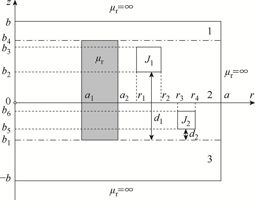
图2 磁屏磁导率无穷大的圆筒铁心线圈截面示意图
Fig.2 Side view of tubular iron-core coils with magnetic shield of infinite permeability
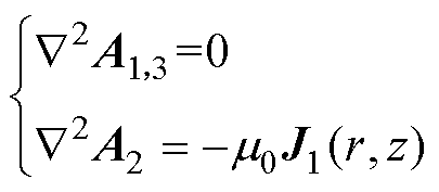
磁矢势A在各区域中分别满足Laplace方程或Poisson方程,即
 (1)
(1)
式中,m0为真空磁导率。
由于模型的轴对称性,磁矢势A在柱坐标中仅有一个分量即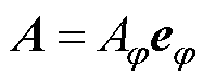 。从而式(1)可简化为对
 的标量微分方程,即
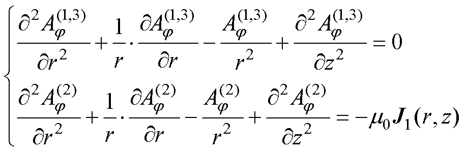 (2)
(2)
以下分析中将省去的下标 以简化表达式。以分离变量法求解式(2)可得
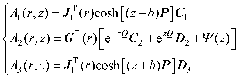 (3)
(3)
式中,P、Q分别为区域1, 3和区域2内本征值pi、qi(i=1, 2, 3, )所组成的对角矩阵;C1、C2、D2、D3为各区域待定系数列向量;
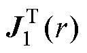 为本征函数
为本征函数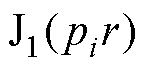 构成的行向量,
 为n阶第一类Bessel函数,
 为区域2的本征函数行向量;上标“T”表示矩阵的转置。的元素
 为归一化本征函数,由式(4)给出。
 (4)
(4)
区域1及区域3本征值pi满足J1(pia)=0。
式(3)第二式的源函数为[23]
 (5)
(5)
其中
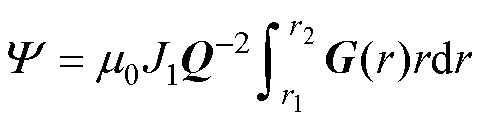 (6)
(6)
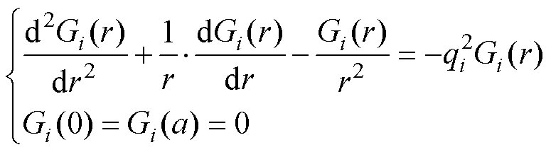
式中,J1为线圈1截面上的电流密度。在ETREE中,式(4)将以1维有限元求解,同时获得本征值qi与本征函数Gi(r),即将式(4)离散化为广义本征值方程
 (7)
(7)
式中,U为本征向量;Ui为第i个本征值所对应的本征向量; 对应本征值;K为刚度矩阵;W为质量矩阵。
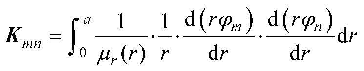 (8)
(8)
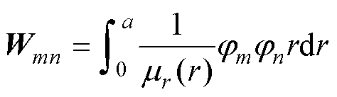 (9)
(9)
式中,jm和jn为由三次Lagrange多项式组成的一维有限元基函数[26];m, n=1,, n0,分别对应基函数的行、列编号,n0为网格元素。本征向量U以矢量归一化技术处理为
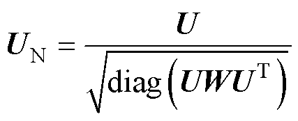 (10)
(10)
式中,UN为归一化本征向量,由其插值得到的本征函数Gi(r)将具有正交归一性,有
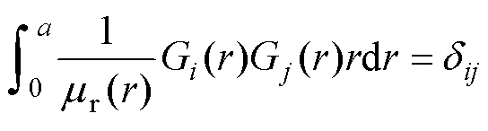 (11)
(11)
式中,dij为Kronecker符号。磁导率函数为
在区域1、2、3交界处,z=b4和z=b1,通过Bz及Hr的连续性可得关于A的两组边界条件,即
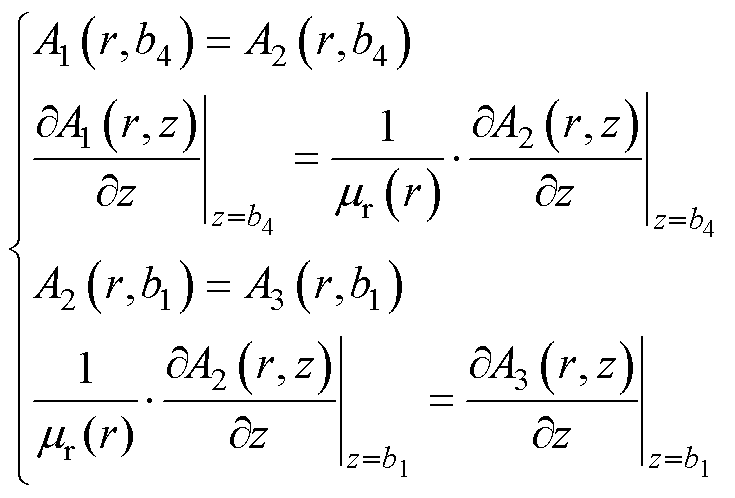 (12)
(12)
将式(3)代入式(12),可得
 (13)
(13)
 (14)
(14)
 (15)
(15)
 (16)
(16)
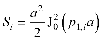
式中,S为对角阵,其对角元为
 (17)
(17)
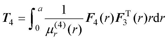
矩阵T为
 (18)
(18)
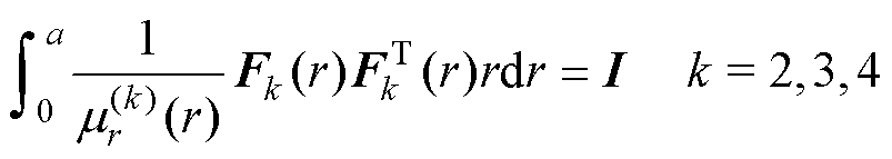
注意,式(13)~式(16)中应用了归一化本征函数Gi(r)的正交归一性(证明见文献[23-24]):
 (19)
(19)
式中,I为单位矩阵。上述表达式中的 和T以Clenshaw-Curtis求积法计算[23-24]。
由式(13)~式(16)消去C1和D3,可得到关于C2和D2的方程组为
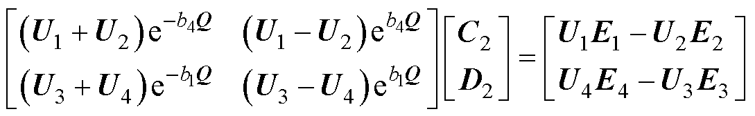 (20)
(20)
其中
 (21)
(21)
 (22)
(22)
 (23)
(23)
 (24)
(24)
 (25)
(25)
 (26)
(26)
 (27)
(27)
 (28)
(28)
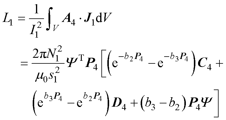
求解式(20)即可得到C2和D2。由此求出线圈1的磁矢势A。进一步利用磁场能量法得到线圈1的自感为
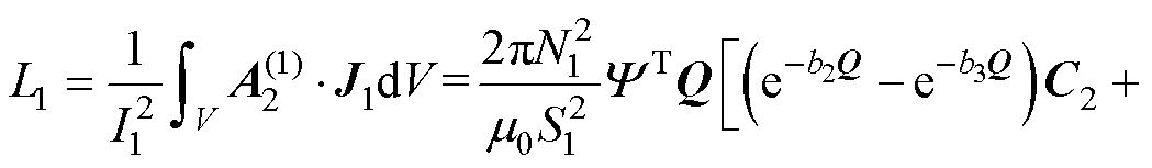
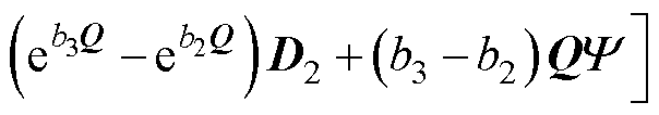 (29)
(29)
式中,N1为线圈1匝数;S1为线圈1截面积,S1= (r2-r1)(b3-b2),r1、r2分别为线圈1的内、外半径,b2、b3分别为线圈1的轴向位置。注意式(29)中令J1=1以简化表达式(电感与电流密度大小无关)。同理得到线圈2自感为
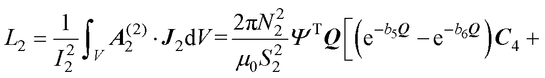
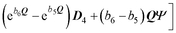 (30)
(30)
式中,N2为线圈2匝数;S2为线圈2截面积,S2=(r4-r3)(b6-b5),r3、r4分别为线圈2的内、外半径,b5、b6分别为线圈2的轴向位置。注意式(30)中的由式(29)中的同一向量做置换r1→r3,r2→r4之后得到(注意式(6))。
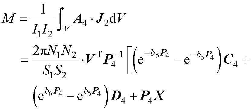
由线圈1、线圈2组成的线圈系统,其互感表达式为
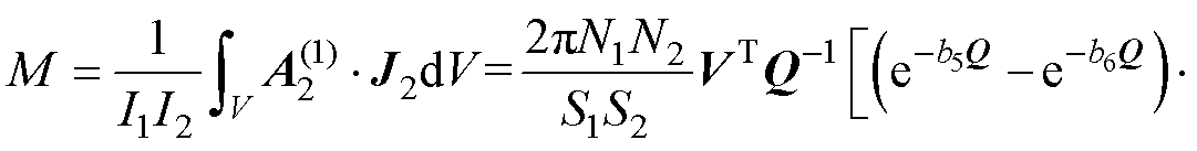
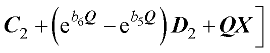 (31)
(31)
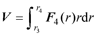
其中
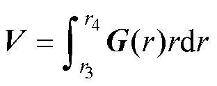 (32)
(32)
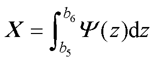
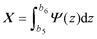 (33)
(33)
在实际应用中,磁屏磁导率显然是有限的,且磁屏也具有一定厚度。本节分析磁屏的有限磁导率和厚度对线圈电感的影响。
首先在柱坐标中建立图3所示的ETREE模型。此ETREE模型将计算域以r=a处的理想导电边界截断,因此整个求解域被限制于r≤a的区域之中。注意在理想导电边界上,磁感应强度的法向分量为零,即Br=0,这等价于A(a, z)=0。另需注意求解域在z方向无限制。此模型中,铁心与磁屏的相对磁导率分别被记为mr与mr1。以数字1~7标记沿着z轴排列的7个区域,分别为:区域1:0≤r≤a, z≥h2;区域2:0≤r≤a, h1≤z≤h2;区域3:0≤r≤a,b4≤z≤h1;区域4:0≤r≤a, b1≤z≤b4;区域5:0≤r≤a, -h1≤z≤b1;区域6:0≤r≤a, -h2≤z≤-h1;区域7:0≤r≤a, z≤-h2。
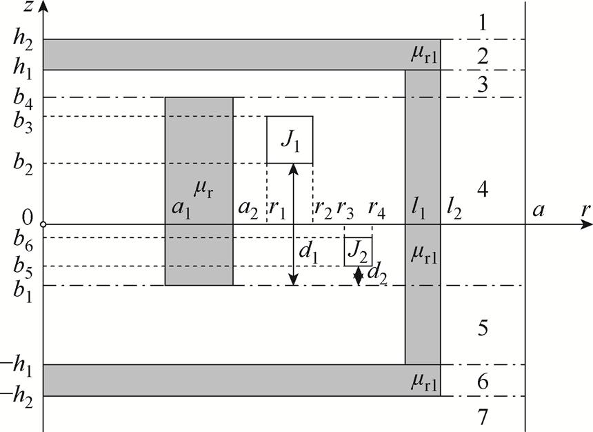
图3 磁屏磁导率有限的圆筒铁心线圈截面示意图
Fig.3 Side view oftubular iron-core coils with magnetic shield of finite permeability
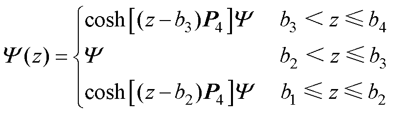
完全类似第1节的分析,由分离变量法可列出各区域磁矢势A(首先只计入线圈1的场):
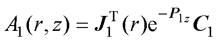 (34)
(34)
 (35)
(35)
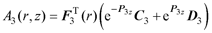 (36)
(36)
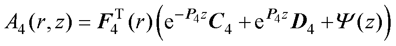 (37)
(37)
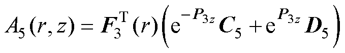 (38)
(38)
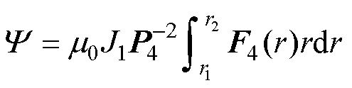
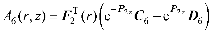 (39)
(39)
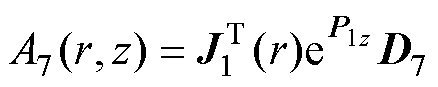 (40)
(40)
式中,J1(r)、F2(r)、F3(r)和F4(r)为列向量,分别包含元素J1(p1,ir)、F2(p2,ir)、F3(p3,ir)和F4(p4,ir),它们是各区域的径向本征函数。p1,i是方程J1(p1,i a)=0的正根。其他本征值p2,i~p4,i通过求解Sturm- Liouville方程统一处理, k=2, 3, 4为区域编号。
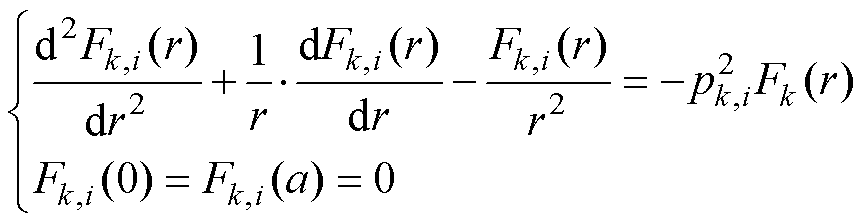 (41)
(41)
式(41)将以一维有限元基函数离散为
 (42)
(42)
其中
 (43)
(43)
 (44)
(44)
本征向量Uk,i将被归一化为
 (45)
(45)
在式(43)和式(44)中,磁导率为
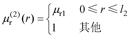 (46)
(46)
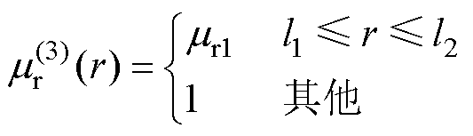 (47)
(47)
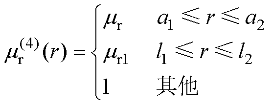 (48)
(48)
另外,式(37)中源函数为
 (49)
(49)
其中
 (50)
(50)
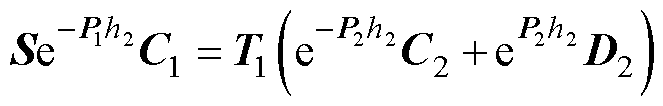
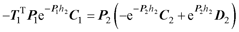
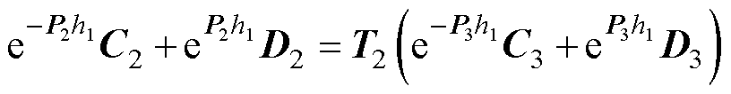
进一步,利用各区域交界面,即z=h2, h1, b4, b1,-h1,-h2的Hr与Bz连续性,结合式(34)~式(40)可得
 (51)
(51)
 (52)
(52)
 (53)
(53)
 (54)
(54)
 (55)
(55)
 (56)
(56)
 (57)
(57)
 (58)
(58)
 (59)
(59)
 (60)
(60)
 (61)
(61)
 (62)
(62)
其中矩阵T1~T4为
 (63)
(63)
 (64)
(64)
 (65)
(65)
 (66)
(66)
S为对角阵,对角元素为
 (67)
(67)
式(51)~式(62)中同样运用了数值本征函数的正交归一性:
 (68)
(68)
上述表达式中的和T1~T4以Clenshaw- Curtis求积法计算。原则上,此处本征值和本征函数也可以通过传统TREE方法获得。然而,显式本征函数将变得非常复杂(包含大量Bessel函数),且本征值的计算效率也很低,因为需要以Newton法或者Cauchy围道积分法处理含有大量Bessel函数的超越方程。
由式(51)~式(62)得到
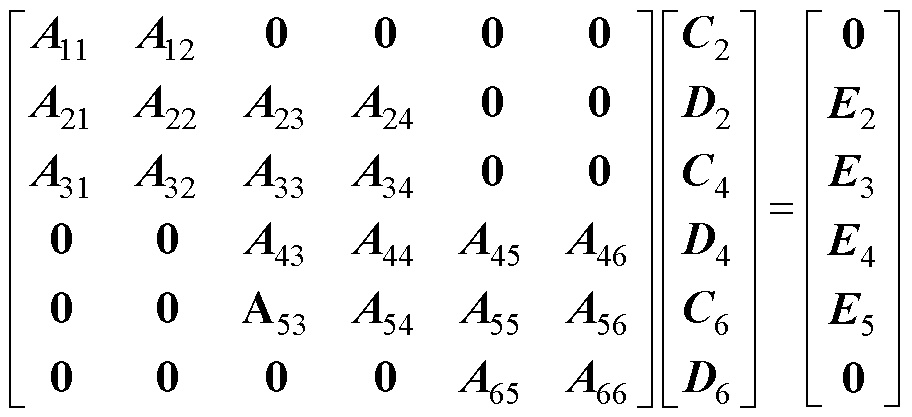 (69)
(69)
其中子矩阵A11~A66和E2~E5在附录中给出。求解式(69),可以求得线圈1的自感为
 (70)
(70)
对于线圈2,其自感L2可以在式(70)中将b2→b5, N1→N2, b3→b6, r1→r3和r2→r4进行替换得到。此外,线圈1和线圈2之间的互感也可以通过同样的方式得到
 (71)
(71)
其中
 (72)
(72)
 (73)
(73)
现对上述ETREE公式进行数值验证。计算与仿真中所用模型参数见表1。在Mathematica®中对ETREE公式进行编码。采用有限元软件COMSOL Multiphysics®中的二维轴对称磁场模块进行仿真计算。计算平台硬件参数:2.3 GHz CPU(Intel Core i9- 9800K),32GB RAM。
表1 ETREE数值计算及仿真的模型参数
Tab.1 Model parameters for ETREE numerical calculations and simulations
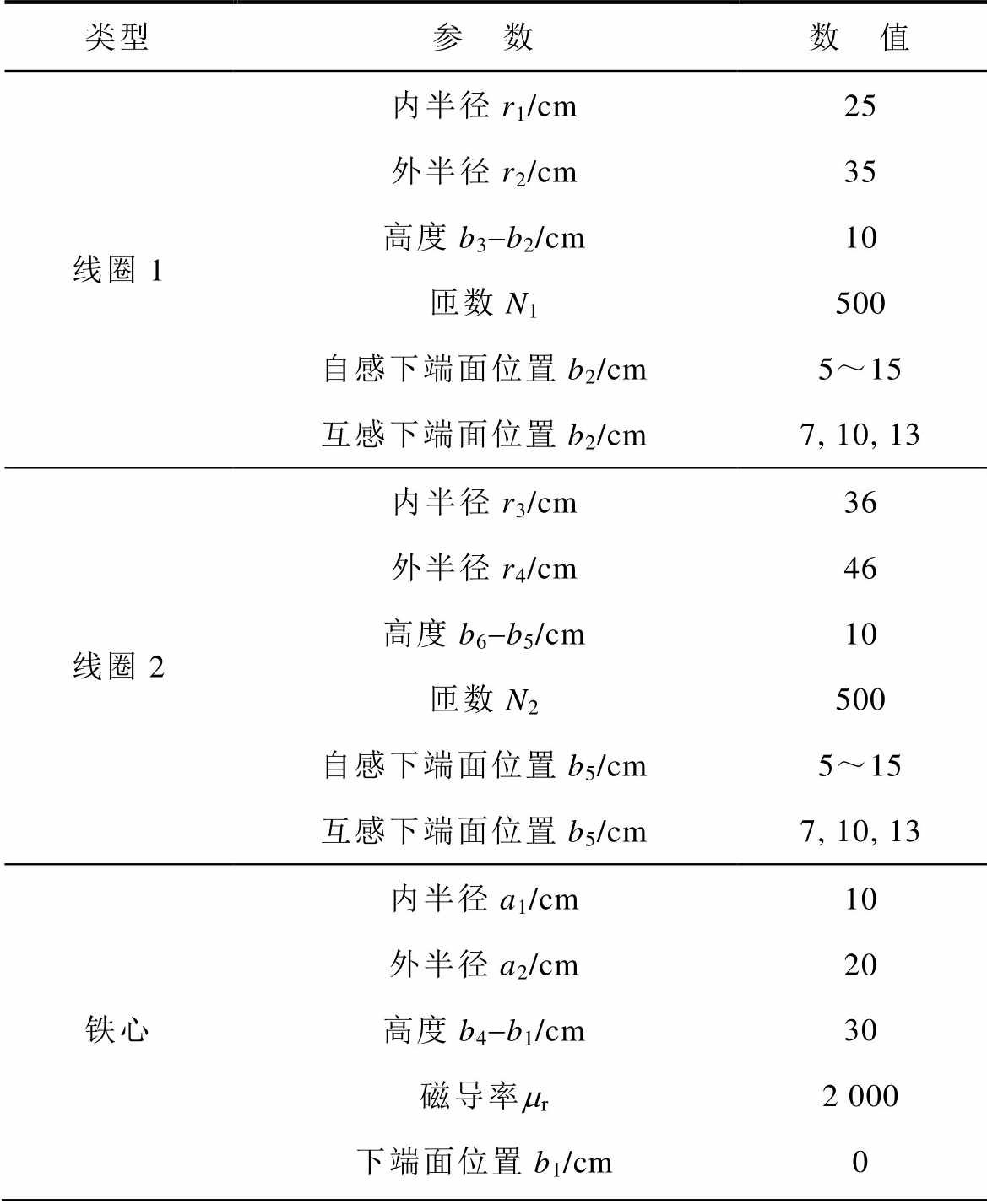
类型参 数数 值 线圈1内半径r1/cm25 外半径r2/cm35 高度b3-b2/cm10 匝数N1500 自感下端面位置b2/cm5~15 互感下端面位置b2/cm7, 10, 13 线圈2内半径r3/cm36 外半径r4/cm46 高度b6-b5/cm10 匝数N2500 自感下端面位置b5/cm5~15 互感下端面位置b5/cm7, 10, 13 铁心内半径a1/cm10 外半径a2/cm20 高度b4-b1/cm30 磁导率mr2 000 下端面位置b1/cm0
(续)
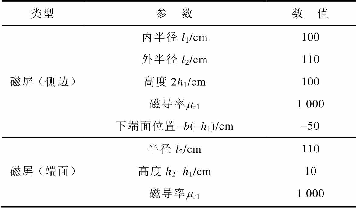
类型参 数数 值 磁屏(侧边)内半径l1/cm100 外半径l2/cm110 高度2h1/cm100 磁导率mr11 000 下端面位置-b(-h1)/cm‒50 磁屏(端面)半径l2/cm110 高度h2-h1/cm10 磁导率mr11 000
在本文数值计算与仿真对照中,铁心下端面位于b1=0;屏蔽上端内表面位于b=h1=50 cm;屏蔽下端内表面位于-b=-h1=-50 cm。
首先对线圈1和线圈2的自感进行数值验证。记线圈1到铁心下端距离为d1=b2-b1,线圈2到铁心下端距离设为d2=b5-b1(见第1、2节图2和图3)。在此算例中,铁心下端距离磁屏下端内表面为b1+h1=50 cm,线圈自感从d1=5 cm开始计算至d1= 15 cm。线圈1的自感曲线如图4所示,其中红色曲线为mr1=∞时的ETREE值,红色圆圈为对应的COMSOL仿真值。蓝色曲线为mr1=1 000时的ETREE值,蓝色三角为对应COMSOL仿真值。mr1=∞与mr1= 1 000时,线圈2的自感ETREE与COMSOL仿真结果如图5所示。
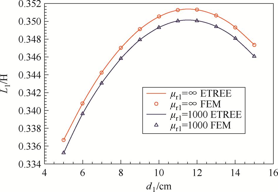
图4 mr1=∞及mr1=1 000时的线圈1自感
Fig.4 Self-Inductance of coil 1 with the magnetic shield of mr1=∞ and mr1=1 000
线圈互感的ETREE与COMSOL对比,也分为mr1=∞与mr1=1 000的两种情况,结果如图6和图7所示。计算时线圈1分别固定于d1=7 cm、10 cm和13 cm,并选取线圈2下端面与铁心下端面间距d2为自变量。其中,ETREE结果由曲线给出,COMSOL仿真则以不同形状小图形标注。
图4~图7的结果显示,ETREE公式与COMSOL仿真结果之间的误差不超过0.5%。
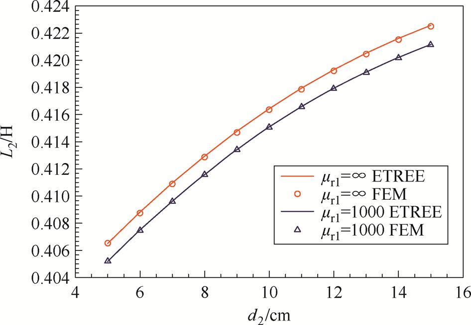
图5 mr1=∞及mr1=1 000时的线圈2自感
Fig.5 Self-Inductance of coil 2 with the magnetic shield of mr1=∞ and mr1=1 000
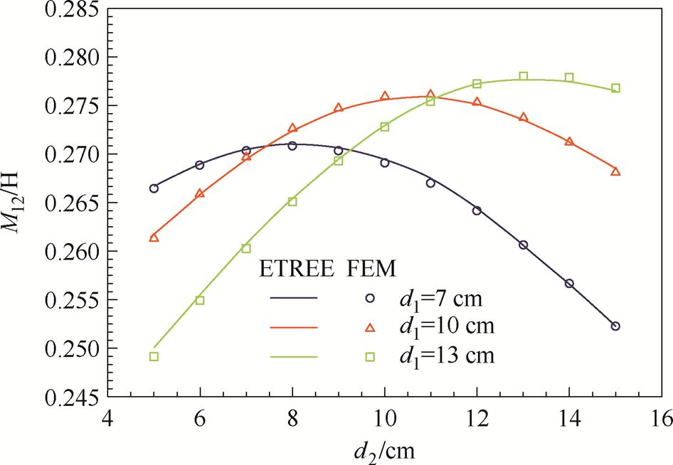
图6 mr1=∞时的线圈互感
Fig.6 Mutual inductance with the magnetic shield of mr1=∞
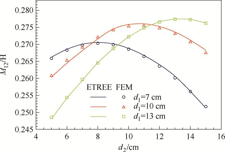
图7 mr1=1 000时的线圈互感
Fig.7 Mutual inductance with the magnetic shield of mr1=1 000
进一步,选取磁屏磁导率与铁心磁导率比值g= mr1/mr为自变量,以ETREE公式计算两线间的互感(见图8)。当铁心磁导率mr>1 000时,磁屏磁导率的增大对线圈互感的影响较小。当g>30%时,增大g对线圈互感影响有限(变化小于2%)。
mr1=∞时,在求和项为40,积分节点为120,剖分元素为500的情况下,求解本征值和本征函数耗时0.4 s,总耗时为0.7 s;mr1=1 000时,在求和项为50,积分节点为150,剖分元素为700的情况下,求解本征值和本征函数耗时0.6 s,总耗时为1.2 s。相较于传统TREE中求解本征值的Newton法(耗时64.5 s),或Cauchy围道积分法(耗时240 s),ETREE的计算效率优势非常明显。
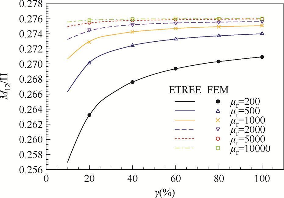
图8 磁屏与铁心磁导率比值g对线圈互感的影响
Fig.8 Influence of the ratio g between the permeability of magnetic shield and tubular iron-core on mutual inductance
由于采用轴对称仿真,COMSOL仿真耗时较短,约为6~7 s(包含剖分及求解耗时)。需要指出的是,对比有限元仿真,ETREE公式的优势不仅在于更高的计算效率。由于各几何参量及材料参数显含在ETREE解中,这将方便于后续的铁心、线圈、磁屏参数优化设计。
最后,基于上述ETREE表达式,进一步计算了磁感应强度值,并将其与无屏蔽情况下铁心线圈的磁感应强度进行对比,以评估磁屏效率。磁感应强度对比测试区间选取如图9所示。
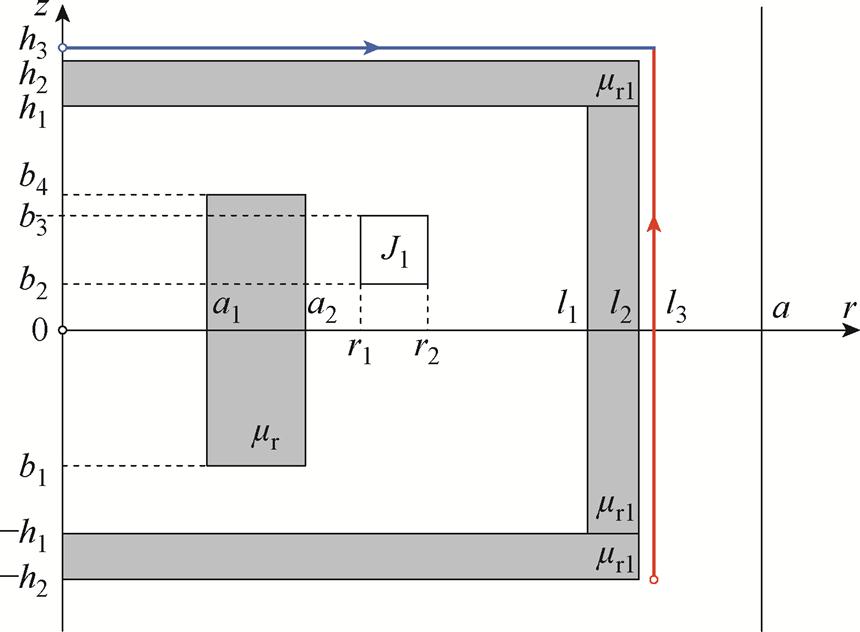
图9 磁感应强度对比测试区间选取
Fig.9 Cover and side paths and initial points for the magnetic induction comparisons
磁屏效率曲线,计算中取mr1=1 000如图10所示。图中曲线由ETREE计算得到。图中纵坐标表示B2与B1的比值,其中B1为图9中沿着红线和蓝线的磁感应强度,B2为对应路径上在无屏蔽条件下的磁感应强度。计算中,mr=1 000,线圈通以10 A电流,d3表示计算点在红线与蓝线上距各自初始点(红色与蓝色圆圈)的距离。具体而言,蓝线对应上屏蔽外侧路径,其初始位置为h3=60.1 cm, r= 0 cm;红线则对应侧屏蔽外侧路径,初始位置为-h2= -60 cm, l3=110.1 cm。结果表明,加入磁屏后,壳外磁场强度相较于无磁屏的铁心线圈显著降低。
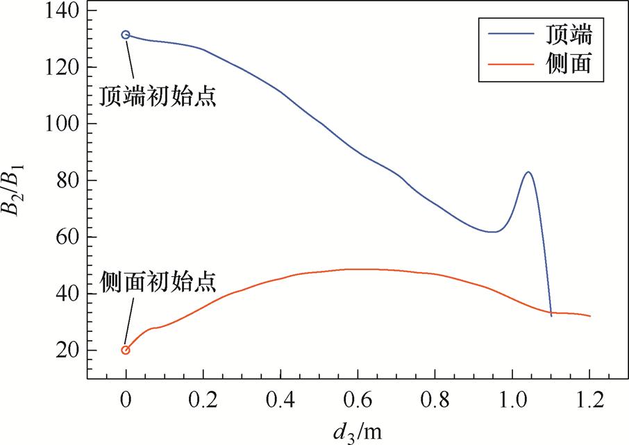
图10 磁屏效率曲线,计算中取mr1=1 000
Fig.10 The efficiency curves of magnetic shield, mr1=1 000
本文以ETREE方法计算了磁屏圆筒铁心线圈的自感与互感,并给出了磁屏磁导率无穷大及磁屏磁导率有限的两种情况下线圈电感公式。数值计算结果表明,本文提出的公式具有与有限元法类似的计算精度,相较于传统的TREE方法,该方法的计算效率提升明显。本文研究结果对此类结构电气设备的优化设计具有一定的实用价值。
附 录
式(69)中的系数如下:
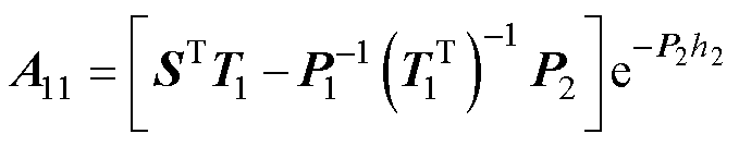
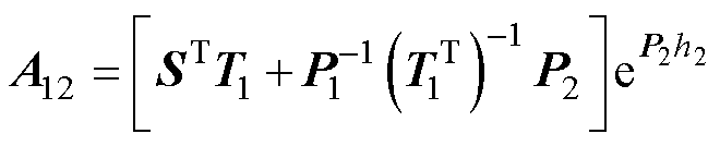
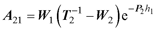


其中
参考文献
[1] Cauer W. Die verwirklichung von wechselstrom- widerständen vorgeschriebener frequenzabhängigkeit [J]. Archiv Für Elektrotechnik, 1926, 17(4): 355-388.
[2] Humpherys D S. The analysis, design, and synthesis of electrical filters[M]. Englewood Cliffs, NJ: Prentice-Hall, 1970: 202-215.
[3] Ho S C, Hwang G J. The study of transient electromagnetic fields in a multi-turn, voltage-excited laminated core reactor[J]. IEEE Transactions on Magnetics, 1989, 25(3): 2699-2705.
[4] Kim J, Kim D H, Choi J, etal. Free-positioning wireless charging system for small electronic devices using a bowl-shaped transmitting coil[J]. IEEE Trans- actions on Microwave Theory and Techniques, 2015, 63(3): 791-800.
[5] 常雨芳, 尹帅帅, 阎晟, 等. 多方位无线电能传输耦合机构设计与分析[J]. 电源学报, 2024, 22(5): 230-241.
Chang Yufang, Yin Shuaishuai, Yan Sheng, et al. Design and analysis of multi-directional WPT coupling mechanism[J]. Journal of Power Supply, 2024, 22(5): 230-241.
[6] 李中启, 包明晗, 孔令军, 等. 无线电能传输系统多孔磁介质任意位置矩形线圈间互感计算方法[J]. 电工技术学报, 2025, 40(24): 7863-7878.
Li Zhongqi, Bao Minghan, Kong Lingjun, et al. Calculation of mutual inductance between rectangular coils at arbitrary positions of porous magnetic media for wireless energy transmission systems[J]. Trans- actions of China Electrotechnical Society, 2025, 40(24): 7863-7878.
[7] 陈彬, 姜鹏飞, 万妮娜, 等. 同轴多层筒式空心线圈自感和互感解析计算方法[J]. 电工技术学报, 2024, 39(20): 6270-6281.
Chen Bin, Jiang Pengfei, Wan Nina, et al. Analytical calculation for self and mutual inductance of coaxial multi layer cylindrical hollow coils[J]. Transactions of China Electrotechnical Society, 2024, 39(20): 6270- 6281.
[8] 刘阳, 张璐, 吴德强, 等. 基于INGO-SVM的输电铁塔地脚螺栓螺母缺失无损检测方法[J]. 高压电器, 2025, 61(2): 130-140.
Liu Yang, Zhang Lu, Wu Deqiang, et al. Non⁃ destructive detection method for nuts missing defect on anchor bolts of transmission tower based on INGO-SVM[J]. High Voltage Apparatus, 2025, 61(2): 130-140.
[9] Buchholz H. Beitragzurtheorie der reaktanzspulen mit offenem eisenkern[J]. Archiv Für Elektrotechnik, 1930,24(3): 285-304.
[10] Buchholz H. Berechnung der reaktanzspulen mit offenem eisenkern[J]. Archiv Für Elektrotechnik, 1932,26(4): 233-249.
[11] Timmerberg J. Kraftwirkung auf eine räumliche zylind- rische Spule infolge eines hochpermeablen Zylinders[J]. Archiv Für Elektrotechnik, 1983, 66(5): 289- 293.
[12] Dodd C V, Deeds W E. Analytical solutions to eddy- current probe-coil problems[J]. Journal of Applied Physics, 1968, 39(6): 2829-2838.
[13] Lubin T, Berger K, Rezzoug A. Inductance and force calculation for axisymmetric coil systems including an iron core of finite length[J]. Progress in Electromagnetics Research B, 2012, 41: 377-396.
[14] Lu Yi, Bowler J R, Theodoulidis T P. An analytical model of a ferrite-cored inductor used as an eddy current probe[J]. Journal of Applied Physics, 2012, 111(10): 103907.
[15] LuoYao. Field and inductance calculations for coaxial circular coils with magnetic cores of finite length and constant permeability[J]. IET Electric Power Appli- cations, 2017, 11(7): 1254-1264.
[16] 陈伟华, 刘岳鹏, 闫孝姮, 等. 心脏起搏器谐振式无线供能四匹配电容无功屏蔽[J]. 电工技术学报, 2025, 40(2): 1-11.
Chen Weihua, Liu Yuepeng, Yan Xiaoheng, et al. reactive shielding of four matching capacitors for resonant wireless power transfer in cardiac pace- makers[J]. Transactions of China Electrotechnical Society, 2025, 40(14): 4382-4394.
[17] 林志远, 李中启, 胡昌轩, 等. 无线电能传输带凸字环形有界磁屏蔽任意位置圆形线圈互感计算方法[J]. 电工技术学报, 2024, 39(16): 4918-4930.
Lin Zhiyuan, Li Zhongqi, Hu Changxuan, et al. Mutual inductance calculation method of arbitrarily positioned circular coils with convex ring type finite magnetic shielding in wireless power transfer[J]. Transactions of China Electrotechnical Society, 2024, 39(16): 4918-4930.
[18] 叶宗彬, 高晨潇, 刘旭. 基于屏蔽极板全双工通信无线电能传输系统[J]. 电工技术学报, 2025, 40(12): 3770-3786.
Ye Zongbin, Gao Chenxiao, Liu Xu. Wireless power transmission system based on full-duplex commu- nication with shielded capacitor plate[J]. Transactions of China Electrotechnical Society, 2025, 40(12): 3770- 3786.
[19] 张宇翔, 何为, 孔晓涵, 等. 基于硅钢片均一化的超低场磁共振抗涡流Z梯度线圈设计方法[J]. 电工技术学报, 2025, 40(4): 987-996.
Zhang Yuxiang, He Wei, Kong Xiaohan, et al. A design method for eddy current-resistant Z-gradient coil in ultra-low field magnetic resonance imaging systems based on homogeneous of silicon steel sheets [J]. Transactions of China Electrotechnical Society, 2025, 40(4): 987-996.
[20] 杨慧娜, 温珺, 丛浩熹. 大容量变压器夹件的电磁力及减振方法研究[J]. 高压电器, 2024, 60(11): 9-17.
Yang Huina, Wen Jun, Cong Haoxi. Study on electro- magnetic force and vibration reduction method of large capacity transformer clamp[J]. High Voltage Apparatus, 2024, 60(11): 9-17.
[21] Kaden H. Die Elektromagnetische Schirmung in Der Fernmelde-Und Hochfrequenztechnik[M]. Cham: Sprin- ger Berlin Heidelberg, 1950.
[22] Theodoulidis T, Bowler J R. Interaction of an eddy- current coil with a right-angled conductive wedge[J]. IEEE Transactionson Magnetics, 2010, 46(4): 1034- 1042.
[23] Luo Yao, Yang Xinyi. Impedance variation in a coaxial coil encircling a metal tube adapter[J]. Sensors, 2023, 23(19): 8302.
[24] Luo Yao, Yang Xinyi, Kyrgiazoglou A. Analytical model of an I-core coil inspecting a metal disk with a borehole and an annular slot[J]. IEEE Sensors Journal, 2024, 24(7): 9765-9771.
[25] Xiang Yike, Luo Yao, Tytko G, et al. Analytical model of an I-core coil inside a metal tube of finite length[J]. Journal of Electromagnetic Waves and Applications, 2024, 38(13): 1464-1479.
[26] Jung M, Langer U. Methode der finiten Elemente für Ingenieure[M]. Wiesbaden, Germany: Springer, 2013.
Abstract The size of air-core coils does not meet the demands of modern electrical devices, which require both compactness and strong anti-interference capabilities. Additionally, air-core coils require a large amount of material due to their high number of turns, and are often susceptible to external interference, leading to instability. To overcome the defects, the air-cored coil is replaced by a tubular iron-core coil with a magnetic shield, where the tubular iron-core can reduce material cost of an iron core without remarkably affecting the inductance values. However, the complex structure makes it challenging to determine the parameters such as self and mutual- inductance. In previous studies, the inductance problems of iron-core coils were typically solved using boundary value problem (BVP) methods. Recently, a novel approach was provided that can solve problem of coil’s inductance with magnetic core effectively. Building on this approach, this paper proposes formulas for calculating self and mutual-inductance of a tubular iron-core coil with a magnetic shield by the enhanced truncated region eigenfunction expansion (ETREE) method.
In Section 1, we firstly address the inductance calculation problem of a tubular iron-core coil with an infinite permeability of the magnetic shield, which consists of three sub-domains in the vertical direction. However, when the permeability of the magnetic shield is not sufficiently large, this assumption may introduce an error. To overcome this limitation, the Section 2 considers the precise permeability and thickness of the magnetic shield. In this case, the coil system has seven sub-domains in vertical direction, requiring more computational steps than in Section 1. By employing the ETREE technique, the resulting equations are simpler and more streamlined than those derived from the traditional TREE method. Matrix operations and the energy method are then applied to efficiently and accurately calculate both self-inductance and mutual inductance.
Simulations by COMSOL Multiphysics® are carried out in this paper to verify the accuracy of the proposed formulas. For the simulation verification of self-inductance, the different positions of coils 1 and 2 are verified respectively. The simulation verification of mutual inductance is carried out by moving coil 2 with fixed coil 1. The results show that the analytical solutions by ETREE technology has high computational efficiency and computational accuracy. In addition, the inductance calculated by an infinite magnetic permeability shield shows a small error (<2%) compared to the results obtained from an accurate magnetic permeability model when the ratio g between permeability of magnetic wall and magnetic core is larger than 30%. In terms of time cost, the method in section 1 consumes around 0.7 seconds whereas the method in section 2 costs averagely 1.2 seconds. For comparison, the corresponding time for the finite elements method is 6~7 seconds.
The following conclusions can be drawn:
(1) The formulas presented in this paper can be used to calculate the inductance of coil systems with varying geometric parameters, magnetic permeabilities, and coil positions, including those for coils, cores, and shields.
(2) The formulas developed in this work exhibit both high accuracy and efficiency. This improvement can be applied to related electrical devices, such as passive filters and iron-core reactors.
(3) Assuming the shield has infinite permeability enhances computational efficiency while maintaining accuracy. However, when the difference between the magnetic permeabilities of the iron core and the shield becomes too large, this assumption introduces significant error. In such cases, the method outlined in Section 2 is recommended.
Keywords:Magnetic shield, inductance of iron-core coils, enhanced truncated region eigenfunction expansion, inductance calculation
禹东泽 男,1994年生,博士,研究方向为计算电磁学。
E-mail: uclydz@163.com
陈柏超 男,1960年生,教授,博士生导师,研究方向为磁控电抗器。
E-mail: whucbc@163.com(通信作者)
中图分类号:TM153+.2
DOI: 10.19595/j.cnki.1000-6753.tces.250121
收稿日期 2025-01-16
改稿日期 2025-02-03
(编辑 郭丽军)