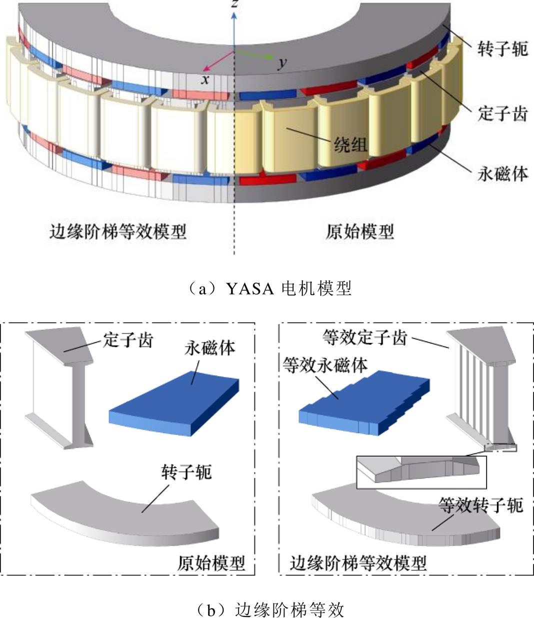
图1 YASA电机阶梯等效建模
Fig.1 Step equivalent model of YASA motor
摘要 为快速准确地确定无轭模块化(YASA)轴向磁通永磁电机的初始设计方案,该文提出一种基于边缘阶梯等效的YASA电机通用三维磁网络模型。首先,通过边缘阶梯等效将电机边缘曲面多边形化,在兼顾电机拓扑结构的同时实现等效磁网络剖分单元的归一化;然后,建立YASA轴向磁通永磁电机通用磁网络模型,计算电机磁场、反电动势等电磁参数;最后,设计并制造一台YASA轴向磁通永磁电机,通过实验验证YASA轴向磁通永磁电机通用磁网络模型的有效性,为三维磁通路径电机设计提供了一种快速准确的计算工具。
关键词:无轭模块化 轴向磁通永磁电机 边缘阶梯等效建模 三维磁路
定子无轭模块化(Yokeless and Segmented Armature, YASA)轴向磁通永磁电机因其功率密度高、绕组端部短、结构紧凑等优点,已成为驱动系统的一种重要选择方案[1-3]。为了快速获得轴向磁通永磁电机的初始方案,通常采用直线电机模型的等效磁路法进行计算[4-5]。然而,这种简化模型无法准确获悉YASA电机磁通的三维分布特征,同时也难以考虑电机的铁心饱和问题,导致计算精度较低。
等效磁网络(Equivalent Magnetic Network, EMN)法因能够考虑铁心饱和且计算速度快而成为轴向磁通电机磁场计算的一种重要方法。文献[6]将YASA电机切为多个直线电机,分别建立EMN模型,并利用修正函数考虑不同径向位置的铁心饱和程度,然而,修正函数基于简化模型推导,未能充分考虑电机的实际形状,导致气隙磁通密度计算结果误差较大。文献[7]对YASA电机建立了径向分层的EMN模型,对比分析了不同分层数下电磁转矩的计算误差,研究结果表明,当分层数超过4时,随着分层数继续增加,误差的下降幅度变得极为有限,表明传统的准三维模型难以通过增加分层数进一步提高计算精度。文献[8]对轮辐式转子的YASA电机建立了EMN模型,研究发现铁心饱和程度计算不准确是EMN误差的主要来源。为考虑磁通的径向路径,文献[9]提出了一种改进的EMN模型,在展开后的多层直线电机间添加径向磁阻,在中径处获得了较为准确的气隙磁通密度计算结果,但在内径和外径处仍存在较大偏差。为解决准三维模型无法完全考虑磁通三维路径的问题,文献[10]通过大量立方体网格近似拟合曲面边缘,建立了基于三维网格的EMN模型,但过多的网格数量导致计算速度较慢。文献[11]则通过非规则形状的三维网络单元建模,因此需要大量积分运算,同样影响计算速度。
为快速准确计算YASA电机磁场三维分布,本文提出一种基于边缘阶梯等效的YASA电机通用模型。首先,提出YASA的电机边缘阶梯等效建模方法。其次,通过边缘阶梯等效获得统一的规则空间十字型网格单元,避免积分运算,并建立YASA电机通用三维EMN模型。最后,基于所提方法设计一台20极24槽YASA电机,实验验证了边缘阶梯等效通用模型的准确性。
YASA电机边缘阶梯等效建模方式如图1所示。等效原则为:
图1 YASA电机阶梯等效建模
Fig.1 Step equivalent model of YASA motor
(1)电机各部分的曲面边缘转化为平面。
(2)等效前后,电机各部分(齿顶、齿身、磁极转子轭)的轴向截面积不变;等效后的EMN模型的剖分仅需使用单一的立方体网络单元,避免了曲面网络单元带来的计算复杂性,同时兼顾了电机的拓扑结构。
建模区域划分如图2所示,可将YASA电机分为三个区域,分别为:转子区域Ⅰ、滑动区域Ⅱ(包含气隙及定子齿顶)及定子区域Ⅲ。基于这一区域划分,构建YASA电机的通用三维EMN模型。
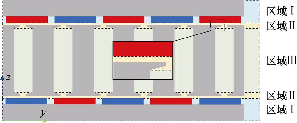
图2 建模区域划分
Fig.2 Model area division
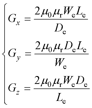
YASA电机通用三维EMN模型的网络单元由空间十字型磁导构成,根据电机磁通走向,分别通过径向x、切向y和轴向z三种磁通路径的等效磁导建立网络单元,如图3a所示。对于径向、切向和轴向三个磁通路径,其等效磁导计算公式[12]为
 (1)
(1)
式中, 为单元轴向长度;
 为单元切向长度,
 为单元径向长度;
 为真空磁导率;
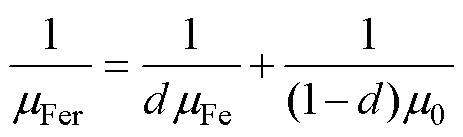
 为相对磁导率。对于铁心径向磁导,则需考虑硅钢片叠压方向磁导率
 ,有
,有
 (2)
(2)
式中, 为铁心磁导率;d为铁心叠压系数。
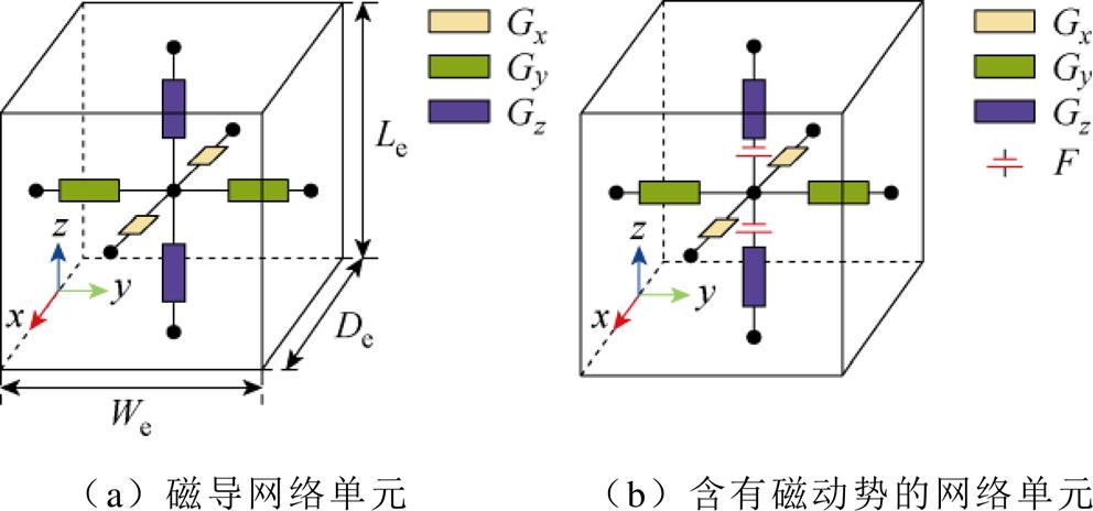
图3 磁网络单元模型
Fig.3 Element models of magnetic network
含有磁动势源 的网络单元如图3b所示,永磁磁动势源Fm方向为永磁体充磁方向,绕组磁动势源Fw方向由右手定则确定,其数值可表示为
 (3)
(3)
式中,Hc为永磁体的矫顽力;Lm为永磁体充磁方向厚度;Cm为永磁体沿充磁方向网络单元数;N为绕组匝数;Ia为电枢电流瞬时值;Cw为绕组磁动势方向上网络单元数。
1)转子区域建模
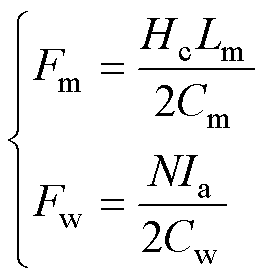
转子区域Ⅰ包括转子轭、永磁体以及极间区域。对于转子轭,首先沿切向方向将其预分为扇环,并对扇环边缘进行阶梯等效。预分扇环时,需确保其与永磁体正对,两侧各延伸半个极间距,获得如图4a所示的转子模块。通过对转子轭与永磁体的边缘进行等效处理,转子模块转化为规则形状,使用立方体网络单元剖分转子模块,即可得到图4b中转子区域EMN模型,其中永磁磁动势以磁动势源Fm添加到永磁体网络单元。
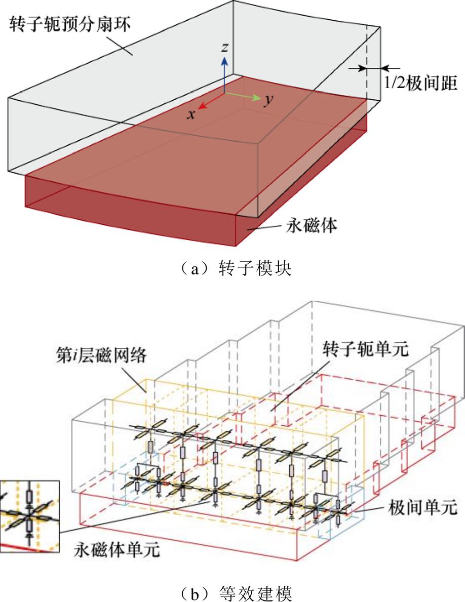
图4 转子区域建模
Fig.4 Model of rotor area
2)定子区域建模
定子区域包括定子齿、定子槽及槽内绕组。由于YASA电机定子本身即为模块化结构,无需预分处理,可直接对单个定子齿进行建模。为实现EMN模型的动态仿真,需将定子齿身与齿顶分离,齿顶在滑动区域中建模。对定子齿身进行边缘等效处理后,使用立方体网络单元进行剖分,即可得到定子齿身区域的EMN模型,如图5a所示。定子齿经边缘等效处理后,电机定子槽已为规则形状,可直接使用立方体网络单元进行剖分,如图5b所示,槽内绕组产生的磁动势以磁动势源Fw添加到定子齿身的网络单元中。
图5 定子区域建模
Fig.5 Model of stator area
3)滑动区域建模
滑动区域包括气隙、定子齿顶及定子槽口。为实现EMN模型对电机的动态模拟,采用混合介质网络单元对YASA电机滑动区域进行建模[13-15]。
混合介质网络单元如图6所示,传统建模方式下定子单元与气隙单元难以规则连接,进行动态运算时,定转子的相对运动将导致节点连接关系突变,增大仿真误差。通过引入混合介质单元,解除了滑动区域齿靴形状与槽口对剖分的限制,使得定子网络单元能够与气隙单元规则连接,从而有效降低动态仿真误差。
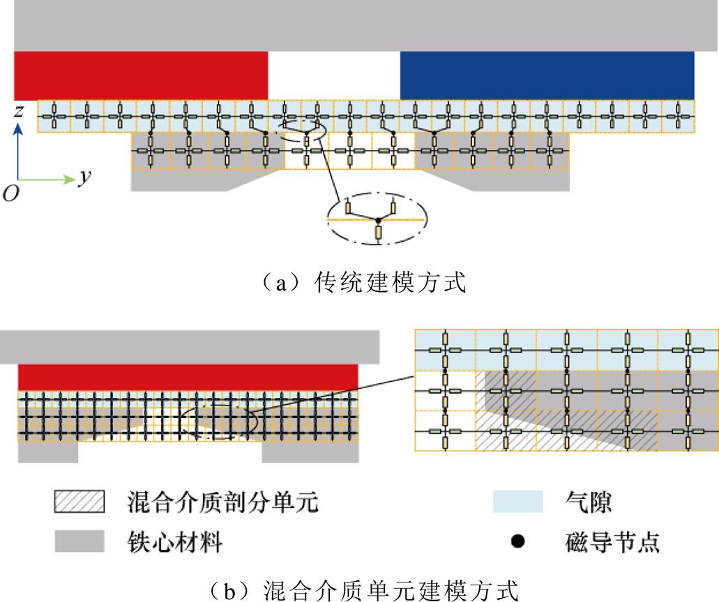
图6 混合介质网络单元
Fig.6 Hybrid medium element
为确保EMN模型获得一个电周期下的电磁特性数据,相关参数需满足约束
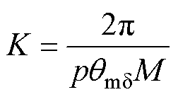 (4)
(4)
式中,K为获得一个电周期波形,节点需要移动的次数;p为极对数; 为气隙网络单元对应的机械角度;M为每次旋转经过的网络个数。
图7为边缘阶梯型等效3D-EMN在一个计算层内一个磁极下的模型,1/2单元电机滑动层包含90个节点,通过改变滑动节点的连接,可实现对电机的动态仿真。基于磁-电类比原理,将磁阻等效为电阻;永磁磁动势源及绕组磁动势源等效为直流电压源,通过Matlab/Simulink软件实现三维EMN模型的求解计算(见附录)[16]。

图7 磁网络模型
Fig.7 Model of EMN
EMN模型的迭代计算过程如图8所示,首先基于假设的初始磁导率,通过式(1)计算磁阻值并将其赋给Simulink中的等效电阻;通过求解Simulink模型,获得网络单元的支路电流,即为对应的磁通,随后利用磁通计算单元磁通密度值,通过B-H曲线计算当前网络单元磁导率,并通过式(5)进行迭代计算;迭代计算的终止条件由式(6)给出,迭代误差 本文取0.005[17]。
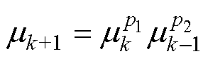 (5)
(5)
式中, 为第k次运算的磁导率;
 、
、 为系数,=0.95,=0.05[18]。
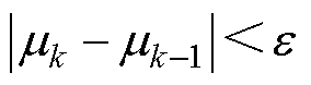 (6)
(6)
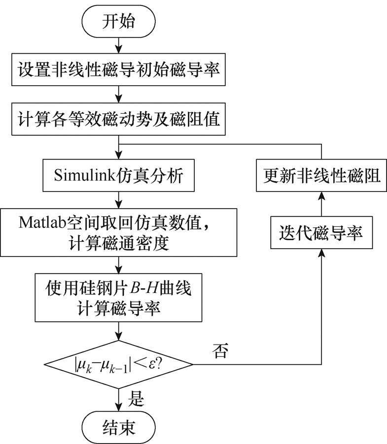
图8 磁网络迭代计算过程
Fig.8 Iterative computational procedure for EMN
基于边缘阶梯等效EMN模型法设计了一台YASA轴向磁通永磁电机,电机参数见表1。
表1 YASA电机的主要参数
Fig.1 Main parameters of the YASA motor
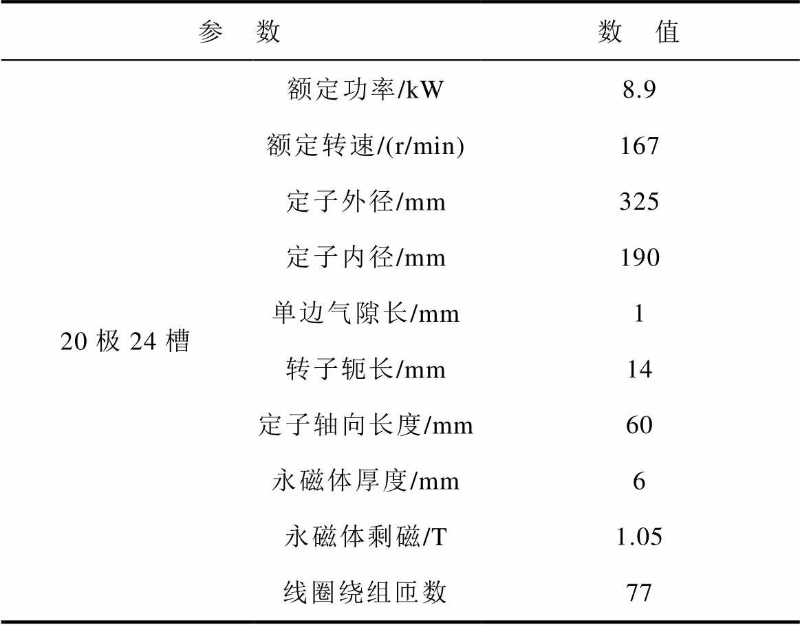
参 数数 值 20极24槽额定功率/kW8.9 额定转速/(r/min)167 定子外径/mm325 定子内径/mm190 单边气隙长/mm1 转子轭长/mm14 定子轴向长度/mm60 永磁体厚度/mm6 永磁体剩磁/T1.05 线圈绕组匝数77
4.1.1 气隙磁通密度
图9a和图9b分别为中径处的空载气隙磁通密度和负载气隙磁通密度;图9c为气隙磁通密度沿径向的分布,其三维特征明显,内外径处气隙磁通密度小,中间处磁通密度大,与文献[19]结论一致。
与有限元法(Finite Element Method, FEM)计算结果相比,EMN1模型(文献[20]中的径向分层模型)空载计算相对误差d=5.23%、负载计算相对误差d=8.90%,EMN2模型(边缘阶梯等效模型)空载计算相对误差d=2.90%、负载计算相对误差d=3.40%,可见EMN2模型具有更高的计算准确度。相对误差d计算方法为
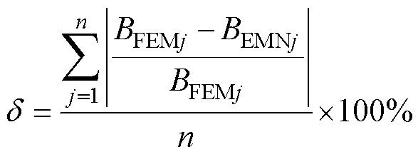 (7)
(7)
式中, 为EMN模型j处磁导的磁通密度;
 为与EMN模型相同位置处FEM所得磁通密度;
 为EMN气隙磁导单元数目。
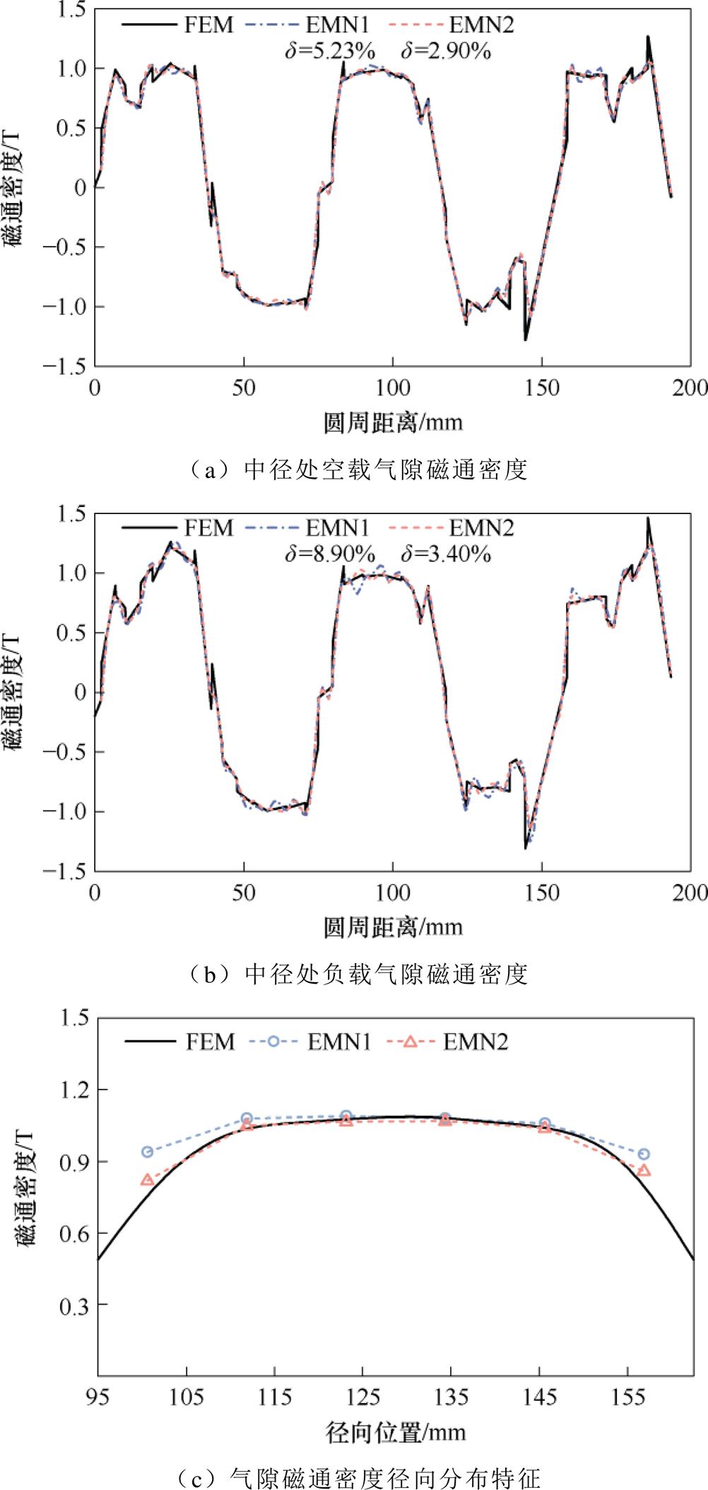
图9 气隙磁通密度
Fig.9 Air gap flux density
图10a、图10b分别为两EMN模型在负载工况下所计算的三维气隙磁通密度;图10c、图10d为EMN模型对比FEM气隙磁通密度的相对误差。可以看出,三维气隙磁通密度误差主要集中在内径与外径处,EMN1在这些区域的磁场误差较大,整体误差显著高于EMN2模型。
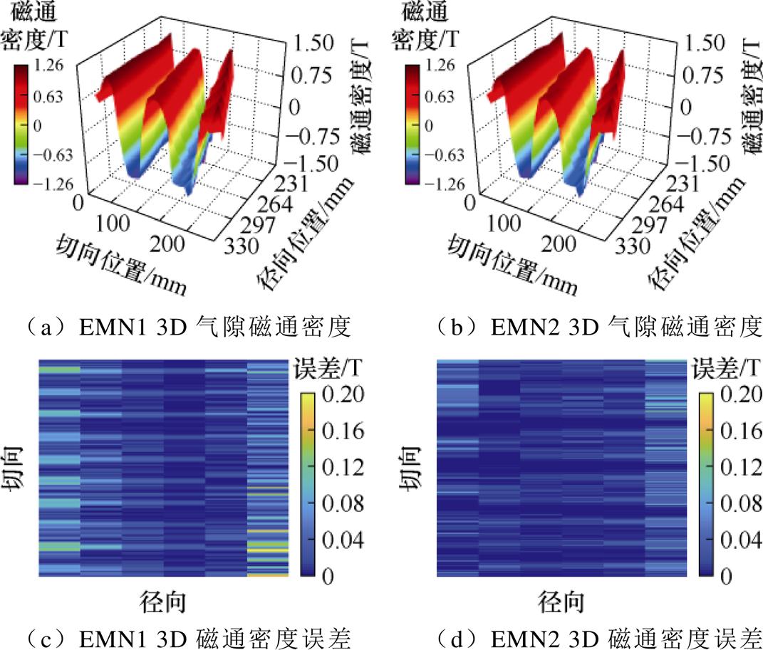
图10 3D气隙磁通密度
Fig.10 3D air gap flux density
4.1.2 齿磁通密度
铁心磁通密度如图11所示。图11a为定子齿磁通密度分布,YASA电机定子铁心在不同径向位置的饱和程度存在差异,定义转子d轴与A相绕组轴线重合时转子位置角 ,分别使用两模型计算
 与
与 两时刻的A相定子齿磁通密度分布,结果如图11b所示。可以看出,齿部饱和程度较低时,两种模型在中径处计算的铁心磁通密度均与FEM结果保持较高一致性。饱和程度较高时,EMN1计算结果出现一定偏差;相比之下,EMN2模型在内径和外径处的磁通密度计算结果更接近FEM,能够更准确地反映铁心的饱和程度。
以FEM所得结果作为基准,两种EMN模型的相对计算时间与相对误差见表2。相较于EMN1模型,在网络单元数量基本相同的情况下,EMN2模型避免了积分运算,计算用时更短,并且与FEM的计算结果一致性更好,可见本文所提建模方法在电机初期设计中能够保证快速性与精确性。
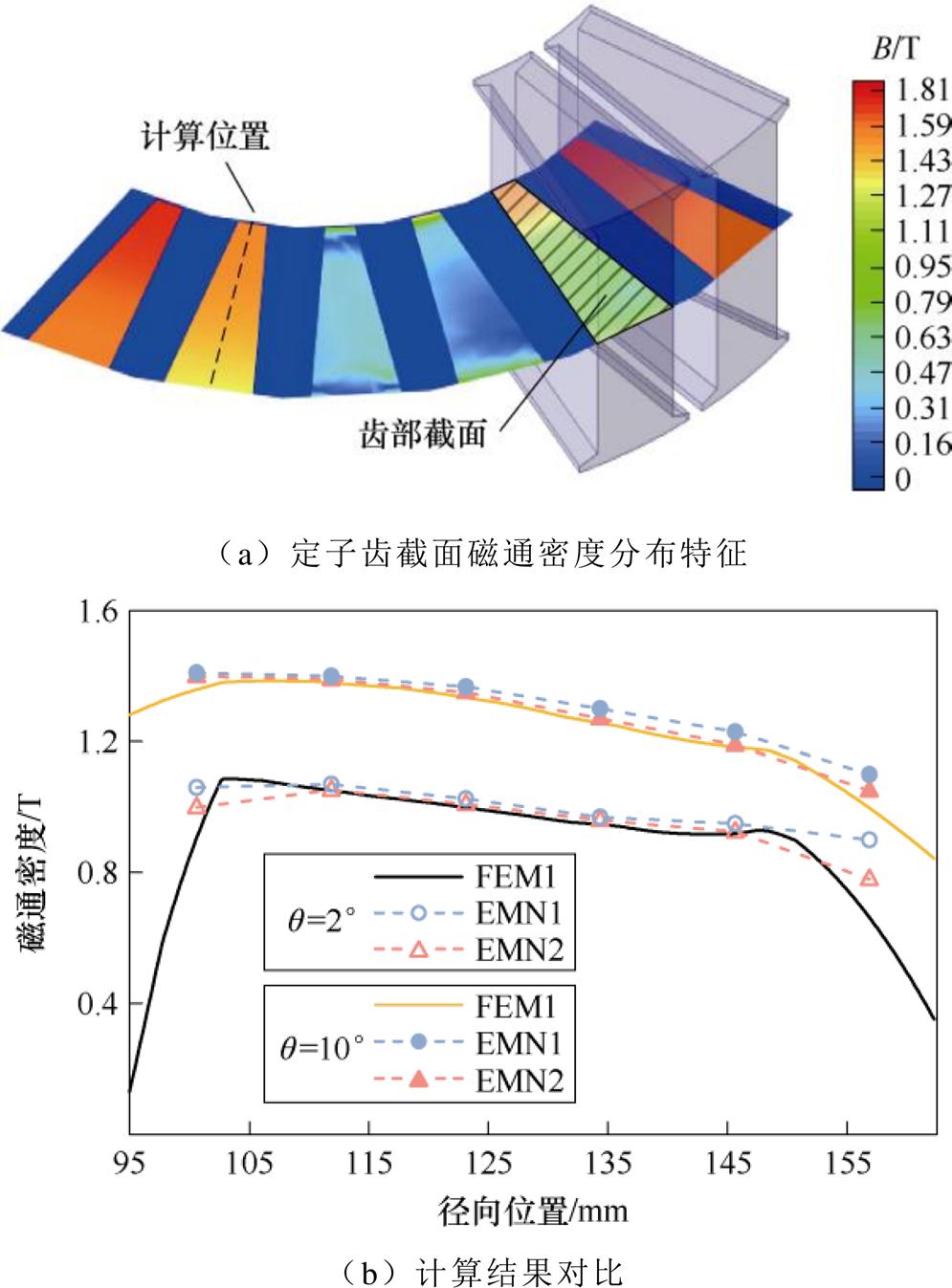
图11 铁心磁通密度
Fig.11 Core flux density
表2 计算结果对比
Tab.2 Comparison of calculation results
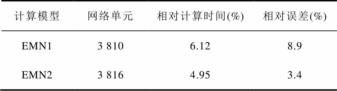
计算模型网络单元相对计算时间(%)相对误差(%) EMN13 8106.128.9 EMN23 8164.953.4
反电动势的计算公式为
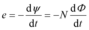 (8)
(8)
式中, 为相磁链;
为相磁链; 为磁通,可通过对磁通密度积分求取,因YASA电机的磁场存在径向分量,磁通密度是关于转子位置角
 和径向位置r的二元函数,因此在求取时,先对EMN模型所得磁通密度进行插值,继而对磁通密度求取积分[21-22]可得
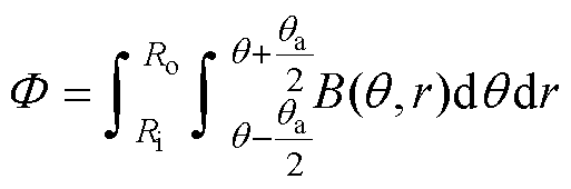 (9)
(9)
式中, 、
、 分别为定子外径与内径;
 为一个线圈的节距角。
空载和负载电动势如图12所示。空载相反电动势如图12a所示,EMN2模型计算所得反电动势有效值为136.89 V,FEM的计算结果为136.07 V;负载相电动势如图12b所示,EMN2和FEM的负载相电动势有效值计算结果分别为149.47 V、148.2 V。对比结果表明,EMN2模型所得结果与FEM的结果基本相同,验证了本文所提EMN模型在电动势计算中的准确性。
电机的电磁转矩计算公式为
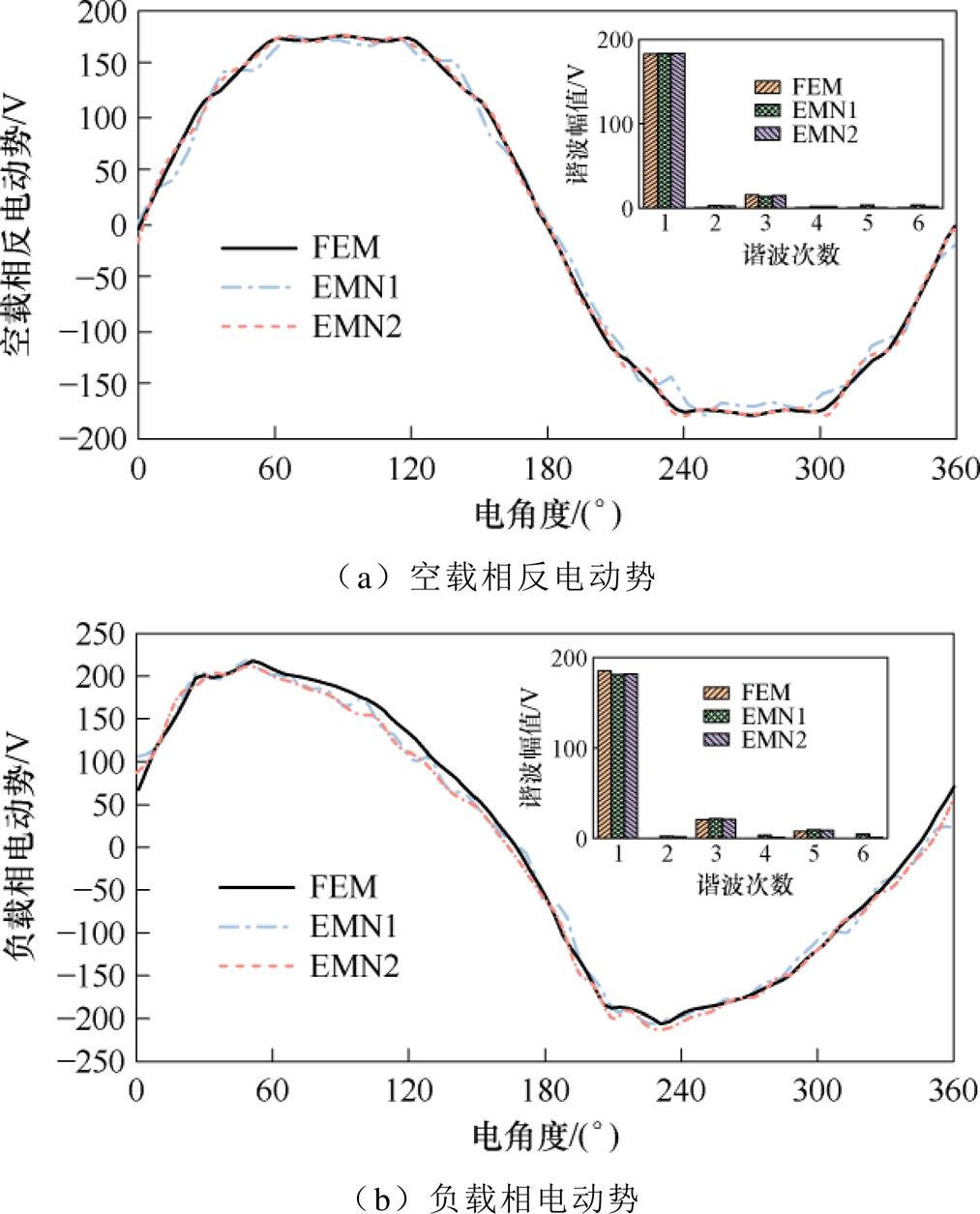
图12 空载和负载电动势
Fig.12 No-load and load electromotive force
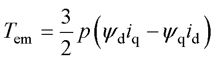 (10)
(10)
式中, 、
、 分别为d、q轴电流;
 、
、 分别为d、q轴磁链。
图13为EMN1、EMN2模型和3D-FEM计算的电磁转矩,平均转矩Tave分别为517.31、502.24和500.11 N·m,EMN2考虑了电机实际拓扑结构,所得转矩数值与3D-FEM结果相近,相对误差减小了3.01%。
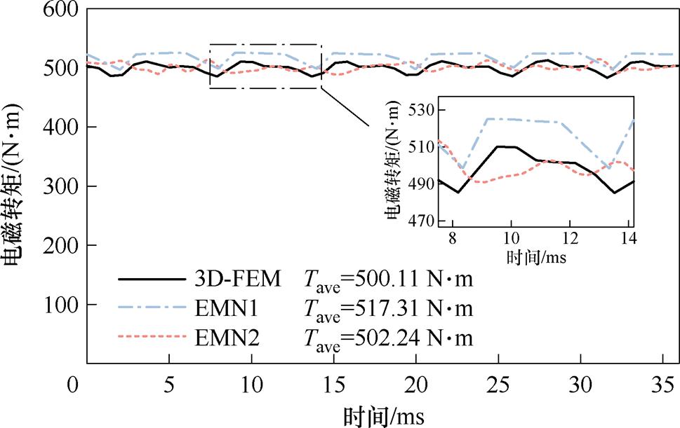
图13 电磁转矩
Fig.13 Electromagnetic torque
为进一步验证所提出的EMN2模型的准确性,依照表1中的参数制造了一台YASA电机,样机和实验测试平台如图14所示,其中控制柜内包含负载电机和YASA样机的控制器。
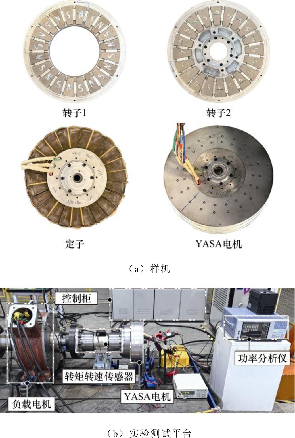
图14 样机与测试平台
Fig.14 Prototype and test platform
图15为转速167 r/min下,样机测试所得反电动势对比。样机空载实验测得的空载反电动势,反电动势有效值为135.628 V,EMN2模型计算的反电动势有效值为136.89 V,二者一致性较好。
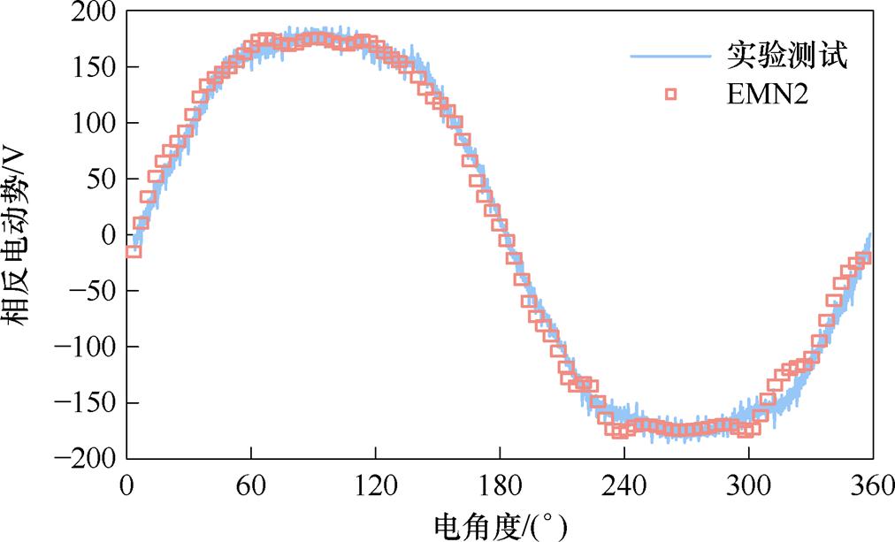
图15 空载反电动势
Fig.15 No-load back electromotive force
额定工况验证如图16所示。图16a为样机在额定转速(167 r/min)、额定转矩(509 N·m)下的电流、电压波形,实测电流有效值为Irms=21.82 A、线电压有效值Urms=285.77 V;在电枢电流Irms=21.82 A时,EMN2模型计算得到的转矩为502.24 N·m,实测转矩为478 N·m,误差为5.07%,电流-转矩曲线如图16b所示。
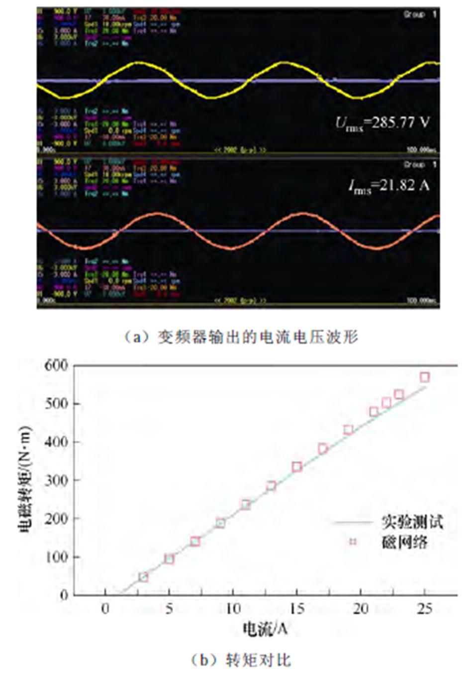
图16 额定工况验证
Fig.16 Rated condition verification
本文针对YASA轴向磁通永磁电机提出了一种通用的三维EMN建模方法,结论如下:
1)电机边缘阶梯等效获得了统一的网络单元,避免了积分运算,提升了计算效率,相较于传统EMN模型,计算速度提高了19.1%。
2)所提边缘阶梯等效YASA电机通用模型不仅考虑了饱和,还考虑了磁通的三维分布特征,基于该模型计算出的反电动势、转矩与实验结果相近,计算精度均优于传统模型。
3)该建模方法具有通用性,可进一步拓展至其他结构轴向磁通电机。
附 录
本文在文献[16]的研究基础上,借助Matlab/Simulink软件,实现对3D-EMN的建模与求解,过程如下。
由本文2.2节和3节可知,网络单元包含径向、切向和轴向三种磁通路径,在建模时,分别通过三条支路进行模拟。附图1a、附图1b分别为在Simulink中搭建的包含非线性磁阻以及包含磁动势源的网络单元。包含非线性磁阻的单元需要进行磁导率迭代,通过在支路上添加电流表获得支路电流(支路磁通)。对元件进行封装后,依照图7所示,连接各网络单元。
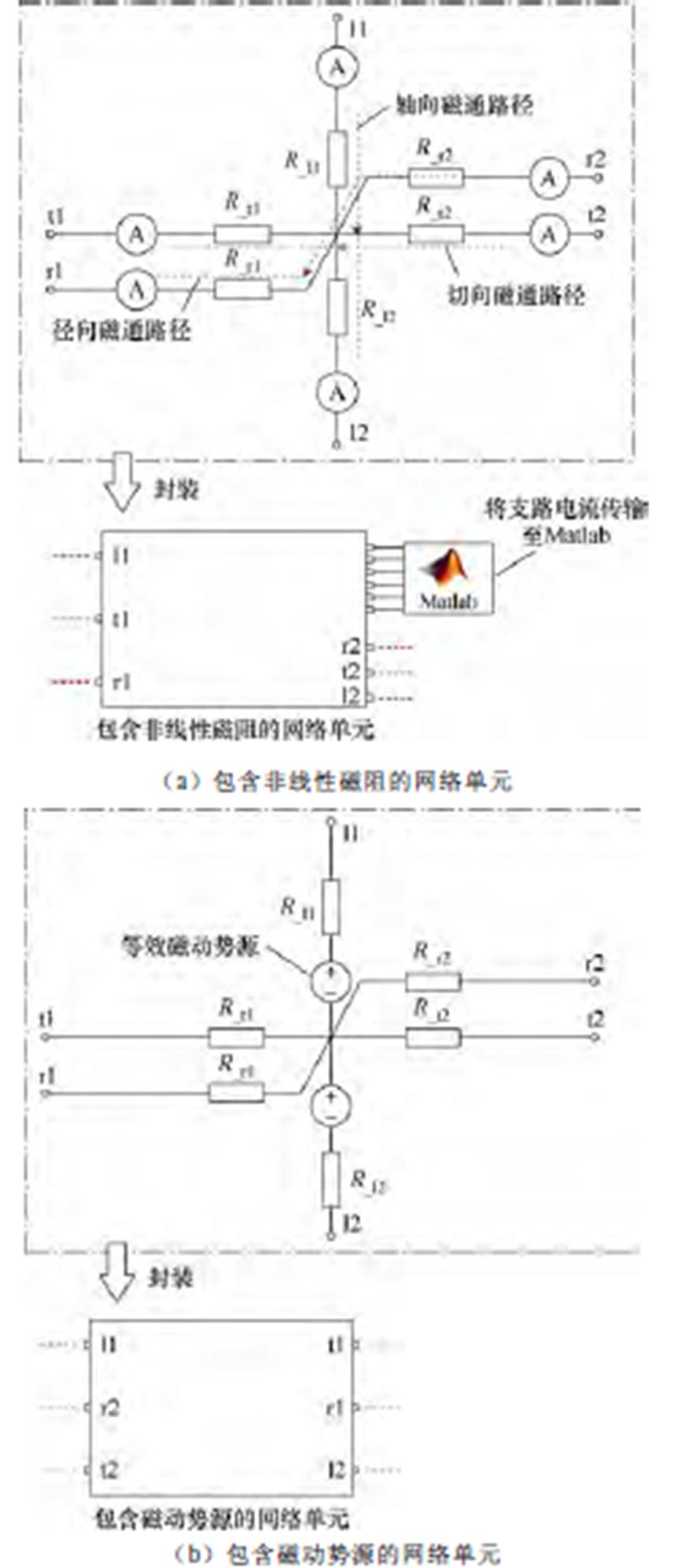
附图1 3D-EMN模型求解方法
App.Fig.1 Solution method of 3D-EMN model
利用Matlab/Simulink软件完成对EMN模型的求解,可得气隙单元j两端的电位差(磁位差),则气隙磁通密度为
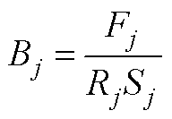 (A1)
(A1)
式中,Bj为单元j处的气隙磁通密度;Fj与Sj分别为j处气隙磁位差及磁通路径方向上的横截面积;Rj为气隙磁阻。
参考文献
[1] 李涛, 张幽彤, 梁玉秀, 等. 定子无磁轭模块化轴向磁通永磁电机研究进展综述[J]. 中国电机工程学报, 2021, 41(1): 340-353, 423.
Li Tao, Zhang Youtong, Liang Yuxiu, et al. An over- view on research progress of yokeless and segmented armature axial flux permanent magnet machine[J]. Proceedings of the CSEE, 2021, 41(1): 340-353, 423.
[2] 高鹏, 任红兴, 王晓远, 等. 磁极径向组合式定子无磁轭模块化轴向磁通电机磁热特性分析[J]. 电工技术学报, 2025, 40(24): 7969-7983.
Gao Peng, Ren Hongxing, Wang Xiaoyuan, et al. Magnetic and thermal characteristics analysis of mag- netic pole radial combination yokeless and segmented armature axial flux machine[J]. Transactions of China Electrotechnical Society, 2025, 40(24): 7969-7983.
[3] 关涛, 刘大猛, 何永勇. 永磁轮毂电机技术发展综述[J]. 电工技术学报, 2024, 39(2): 378-396.
Guan Tao, Liu Dameng, He Yongyong. Review on development of permanent magnet in-wheel motors[J]. Transactions of China Electrotechnical Society, 2024, 39(2): 378-396.
[4] Geng Weiwei, Hou Jining, Li Qiang. Electromagnetic analysis and efficiency improvement of axial-flux permanent magnet motor with yokeless stator by using grain-oriented silicon steel[J]. IEEE Transa- ctions on Magnetics, 2022, 58(2): 8200905.
[5] 佟文明, 杜绍雨, 贾建国, 等. 基于改进复相对磁导函数的开槽轴向磁通永磁电机气隙磁场解析模型[J]. 电工技术学报, 2024, 39(24): 7700-7711.
Tong Wenming, Du Shaoyu, Jia Jianguo, et al. Analytical model of air-gap magnetic field of slotted axial flux permanent magnet motor based on improved complex relative permeance function[J]. Transactions of China Electrotechnical Society, 2024, 39(24): 7700- 7711.
[6] Tak B O, Ro J. Analysis and design of an axial flux permanent magnet motor for in-wheel system using a novel analytical method combined with a numerical method[J]. IEEE Access, 2020, 8: 203994-204011.
[7] Hemeida A, Lehikoinen A, Rasilo P, et al. A simple and efficient quasi-3D magnetic equivalent circuit for surface axial flux permanent magnet synchronous machines[J]. IEEE Transactions on Industrial Elec- tronics, 2019, 66(11): 8318-8333.
[8] Jia Lun, Lin Mingyao, Lin Keman, et al. Design and analysis of axial-flux modular spoke-type permanent magnet machines with segmented stators for traction applications[J]. IEEE Transactions on Transportation Electrification, 2024, 10(2): 4290-4301.
[9] Sun Xining, Wang Limei, Fan Xinggang, et al. A quasi-three-dimensional magnetic equivalent circuit model of yokeless and segmented armature axial flux motors considering radial segmentation magnetic coupling[C]//2022 IEEE Transportation Electrifi- cation Conference and Expo, Asia-Pacific (ITEC Asia-Pacific), Haining, China, 2022: 1-6.
[10] Li Nian, Zhu Jianguo, Lin Mingyao, et al. Analysis of axial field flux-switching memory machine based on 3-D magnetic equivalent circuit network considering magnetic hysteresis[J]. IEEE Transactions on Mag- netics, 2019, 55(6): 7203104.
[11] Hou Jining, Geng Weiwei, Li Qiang, et al. 3-D equivalent magnetic network modeling and FEA verification of a novel axial-flux hybrid-excitation in-wheel motor[J]. IEEE Transactions on Magnetics, 2021, 57(7): 8106912.
[12] 王超, 彭兵, 闫伟, 等. YASA轴向磁通永磁电机定子槽漏感计算[J]. 中国电机工程学报, 2024, 44(10): 4082-4091.
Wang Chao, Peng Bing, Yan Wei, et al. Calculation of slot inductance of axial flux permanent machine with yokeless and segmented armature[J]. Pro- ceedings of the CSEE, 2024, 44(10): 4082-4091.
[13] Li Guidan, Dong Zun, Li Bin, et al. An improved equivalent magnetic network model of modular IPM machines[J]. IEEE Transactions on Magnetics, 2022, 58(4): 8104609.
[14] Liu Guohai, Wang Yong, Chen Qian, et al. Design and analysis of a new equivalent magnetic network model for IPM machines[J]. IEEE Transactions on Magnetics, 2020, 56(6): 8101112.
[15] 朱旭光, 刘正蒙, 刘国海, 等. 基于混合介质网格的表贴式永磁游标电机通用等效磁网络模型[J]. 中国电机工程学报, 2024, 44(5): 2009-2019.
Zhu Xuguang, Liu Zhengmeng, Liu Guohai, et al. General equivalent magnetic network model of surface permanent magnet vernier machine based on hybrid medium mesh[J]. Proceedings of the CSEE, 2024, 44(5): 2009-2019.
[16] Huang Yunkai, Zhou Tao, Dong Jianning, et al. Magnetic equivalent circuit modeling of yokeless axial flux permanent magnet machine with segmented armature[J]. IEEE Transactions on Magnetics, 2014, 50(11): 8104204.
[17] Ghods M, Faiz J, Bazrafshan M A, et al. A mesh design technique for double stator linear PM vernier machine based on equivalent magnetic network modeling[J]. IEEE Transactions on Energy Con- version, 2022, 37(2): 1087-1095.
[18] 佟文明, 王萍, 吴胜男, 等. 基于三维等效磁网络模型的混合励磁同步电机电磁特性分析[J]. 电工技术学报, 2023, 38(3): 692-702.
Tong Wenming, Wang Ping, Wu Shengnan, et al. Electromagnetic performance analysis of a hybrid excitation synchronous machine based on 3D equi- valent magnetic network[J]. Transactions of China Electrotechnical Society, 2023, 38(3): 692-702.
[19] Seyedi S M, Sharifi A H, Mohammadi A A. Com- putation of armature reaction field and full-load characteristics of an axial flux surface mounted PM machine using a new analytical approach[C]//Iranian Conference on ElectricalEngineering (ICEE), Mashhad, Iran, 2018: 1027-1031.
[20] 黄允凯, 周涛. 基于等效磁路法的轴向永磁电机效率优化设计[J]. 电工技术学报, 2015, 30(2): 73-79.
Huang Yunkai, Zhou Tao. Efficiency optimization design of axial flux permanent magnet machines using magnetic equivalent circuit[J]. Transactions of China Electrotechnical Society, 2015, 30(2): 73-79.
[21] 佟文明, 姚颖聪, 李世奇, 等. 考虑磁桥不均匀饱和的内置式永磁同步电机等效磁网络模型[J]. 电工技术学报, 2022, 37(12): 2961-2970.
Tong Wenming, Yao Yingcong, Li Shiqi, et al. Equivalent magnetic network model for interior permanent magnet machines considering non-uniform saturation of magnetic bridges[J]. Transactions of China Electrotechnical Society, 2022, 37(12): 2961- 2970.
[22] 吴胜男, 庞先文, 佟文明, 等. 模块化定子混合励磁同步电机磁网络建模与分析[J]. 电机与控制学报, 2023, 27(12): 95-104.
Wu Shengnan, Pang Xianwen, Tong Wenming, et al. Modeling and analysis of magnetic network of modular stator hybrid excitation synchronous motors[J]. Elec- tric Machines and Control, 2023, 27(12): 95-104.
Abstract Due to the advantages of high power density, short end windings, and compact structure, the yokeless and segmented armature (YASA) axial flux permanent magnet motor has become an essential choice for high-performance drive systems such as electric vehicles and aerospace. The equivalent magnetic network (EMN) method considers core saturation and offers a fast calculation speed for determining the magnetic field of an axial flux motor. However, the traditional EMN method cannot accurately estimate the three-dimensional (3D) flux distribution characteristics or fully consider the actual topology of the motor, resulting in an insufficiently accurate initial design scheme. Therefore, this paper proposes a general 3-D EMN model based on edge step equivalent, which provides a fast and precise calculation tool for the initial design of the YASA motor.
Firstly, the topology of the stator and rotor structures of the YASA motor is introduced, and the edge-step equivalent EMN modeling method is proposed. This method transforms the complex topology structure into a regular cube network unit by approximately mapping the motor's curved surface to a plane through an equivalent edge step. Thus, the computational complexity caused by the curved surface network unit can be avoided. The YASA motor is divided into the rotor, sliding (including the air gap and the stator tooth top), and stator areas. The 3-D EMN model is established. The sliding area utilizes a hybrid medium network unit to address the dynamic connection issue between the stator and rotor nodes. Secondly, taking a 20-pole 24-slot YASA motor as an example, the traditional model, the edge step equivalent model, and the finite element method (FEM) are compared in terms of air gap flux density, stator tooth flux density, back electromotive force (EMF), and electromagnetic torque. Finally, a YASA motor is manufactured, and its effectiveness is verified through experiments.
Compared to the traditional EMN, the edge step equivalent EMN can accurately calculate the 3D magnetic flux distribution and consider the core saturation effect. The relative error of the no-load and load air gap flux density of the edge step equivalent EMN is 2.9% and 3.4%, respectively, significantly lower than those of the traditional EMN. The effective value of the back EMF, measured by the no-load experiment at the rated speed, is 135.62 V, while that calculated by the edge step equivalent EMN model is 136.89 V. Under the rated load condition, the torque calculated by the model is 502.24 N·m, while the measured torque is 478 N·m, resulting in an error of approximately 5.07%.
The following conclusions can be drawn. (1) Edge step equivalent EMN obtains a unified network unit, avoids the integral operation, and improves the calculation efficiency. Compared with the traditional EMN model, the calculation speed is improved by 19.1%. (2) The proposed general edge step equivalent EMN model of the YASA motor not only considers the saturation, but also considers the 3-D distribution characteristics of the magnetic flux. The back EMF and torque calculated based on this model are similar to the experimental results, and the calculation accuracy is better than that of the traditional EMN model. (3) The modeling method is universal and can be further extended to other axial flux motors.
Keywords:Yokeless and segmented armature, axial flux permanent magnet motor, edge step equivalent model, 3D magnetic circuit
中图分类号:TM351
DOI: 10.19595/j.cnki.1000-6753.tces.250074
收稿日期 2025-01-11
改稿日期 2025-02-10
蒋尚轩 男,2000年生,博士研究生,研究方向为高转矩密度永磁同步电机。
E-mail: 2377378904@qq.com(通信作者)
彭 兵 男,1975年生,教授,博士生导师,主要研究方向为永磁电机及特种电机设计。
E-mail: pengbing_gd@163.com
(编辑 崔文静)