图1 基于CHB-PET的交直流微电网拓扑
Fig.1 Topology of AC/DC microgrid based on CHB-PET
摘要 级联型电力电子变压器(CHB-PET)可实现交直流微电网、储能装置等可再生能源和直流负荷的柔性互联。针对某实际工程中CHB-PET通过互为备用的两条交流短引线接入不同母线段的场景,考虑CHB-PET交流短引线发生故障后,备用短引线需快速投入,以实现CHB-PET供电的快速恢复。但常规方案无法判别备用短引线投入时是否存在故障,存在将故障短引线接入的风险。针对此问题,该文提出一种基于CHB-PET与直流微电网协同控制,并主动注入特征电压以实现短引线安全投入的方案。故障发生后,首先闭锁CHB-PET的输入级以实现故障隔离;其次切换±375 V直流微电网所连接的储能装置为直流电压控制,维持±375 V直流母线电压稳定以及直流微电网负荷等装备的正常运行;然后解锁CHB-PET的输入级并切换为定U/f控制,向备用短引线注入特征电压来检测是否存在故障点,并进一步提出一种计及电流不平衡因子的故障检测方法,减少故障检测所需时间,从而实现备用短引线的快速安全投入;最后,利用PSCAD/EMTDC仿真平台和半实物硬件在环实验平台验证所提出方案的可行性和有效性。
关键词:故障检测 级联型电力电子变压器 主动注入 协同控制
级联型电力电子变压器(Power Electronic Transformer with Cascaded H-Bridge, CHB-PET)[1]实现了交直流线路的柔性互联、潮流的灵活控制和新能源的便捷高效接入[2-3],对于提高供电可靠性和设备利用率有显著优势[4]。实际工程中,CHB-PET通过两条互为备用的短引线1和2分别接入分段母线Ⅰ段和Ⅱ段。正常运行时由Ⅰ段母线供电,在短引线1发生故障后,隔离短引线1,将短引线2接入CHB-PET[5],实现供电的快速恢复。但现有方案无法判别备用短引线投入时是否存在故障,若将含有故障点的备用短引线接入,会对电力电子装备的安全造成较大影响[6-7]。因此,进行CHB-PET备用短引线接入前的故障检测,并实现短引线的安全投入具有重要意义[8-10]。
在故障检测方面,文献[11]将不同层级的保护功能集成,通过比较不同区域的主馈线和从馈线的正序电流故障分量的相位特征差异实现故障定位。文献[12]针对主、备过电流继电器在微电网发生故障后配合不利的问题,利用正负序电流的相位差异实现故障方向的判别。文献[13]针对可再生能源并网带来的保护误动问题,利用短时间内序电流及其方向变化来定位故障。文献[14]将一维的时域信号转换为图像信号,充分利用卷积神经网络在图像识别中的优势来检测故障。由于不同负荷类型引起的电弧特性有所差异,文献[15]采用特征化指标以减小不同类型故障带来的特性重叠问题。针对无源网络,文献[16]利用换流器向正常线路和故障线路注入特征信号,提出了一种基于行波的故障检测方法,但该方法对于输电线路近端和远端的识别精度不足,需提升采样频率和特征电压幅值来弥补此缺陷。
在备用线路故障探测及安全投入方面,文献[17]通过正交控制方法,保证了附加控制策略和基础控制策略互不影响,有效地减小了主动探测式保护对原控制系统的影响。文献[18]针对光伏并网换流器弱馈特性导致的保护拒动问题,提出了基于换流器主动注入的保护新原理,提高了保护的选择性。文献[19]分析了主动探测式故障识别方法的核心思路及关键技术,给出了不同场景下主动注入特征信号的设计原则及重要实例。文献[20-22]针对逆变型电源在不同工况下故障特性不同导致保护整定及故障选相困难的问题,提出了基于控保协同的主动注入式保护方法,有效地消除了逆变型电源对保护整定的影响,并显著提升了选相元件的动作正确性。文献[23]针对海缆故障定位困难的问题,提出了基于控保协同的故障探测方法,利用本地量信息完成了对海缆全区段的故障判别及保护。文献[24-25]针对分布式电源对备自投动作的影响,利用频差检测、断路器动作和备用电源供应构造了完整的目标函数,建立了更贴合电网运行工况的备自投策略流程,但该方案尚未考虑电力电子装置对故障过程的影响。文献[26-28]针对故障后残压影响备自投动作时间和检无压过程的问题,根据水电并网后故障初期频率不可突变的特点,提出了改进动作逻辑的备自投方案以及故障后光伏电站的快速可靠分断策略,有效地降低了新能源对备自投的影响。
综上所述,目前国内外学者尚未对CHB-PET备用短引线接入前的故障检测和安全投入开展研究。针对此问题,本文提出了一种基于CHB-PET与直流微电网储能装置协同控制并主动注入特征电压的备用短引线故障检测及安全投入方案。此方案包括三个阶段:短引线故障隔离阶段(阶段一)、CHB-PET与直流微电网储能装置协同控制阶段(阶段二)和备用短引线故障检测及投入阶段(阶段三)。
在阶段一,仅闭锁级联H桥(Cascaded H-Bridge, CHB),实现CHB-PET与故障点的隔离。在阶段二,切换±375 V直流储能装置为稳压控制模式,与CHB- PET隔离级采用协同控制策略,保证±375 V直流母线电压和PET中压直流电容电压稳定。在阶段三,解锁CHB向备用短引线注入特征电压以检测是否存在故障,并提出了计及电流不平衡因子的故障检测判据,减少了故障检测所需时间。最后在PSCAD/ EMTDC仿真平台和半实物硬件在环(Hardware In the Loop, HIL)实验平台验证了所提方案。
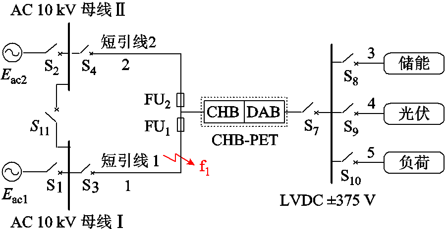
图1所示为含CHB-PET和储能装置的交直流微电网拓扑。中压交流电压等级为10 kV,低压直流电压等级为±375 V,CHB-PET交流端口有两条交流进线。Ⅰ段和Ⅱ段母线经短引线1和2接入CHB-PET。
图1 基于CHB-PET的交直流微电网拓扑
Fig.1 Topology of AC/DC microgrid based on CHB-PET
正常运行时,S1、S2和S3闭合,S4断开,由Ⅰ段母线向CHB-PET供电,Ⅱ段母线作为备用。直流端口连接±375 V母线,直流微电网储能、光伏及负荷经Buck-Boost换流器接入±375 V母线。图1中,S1~S4为交流断路器,FU1、FU2为熔断器,S7~S10为直流断路器。
级联型电力电子变压器(CHB-PET)的拓扑及控制策略如图2所示。
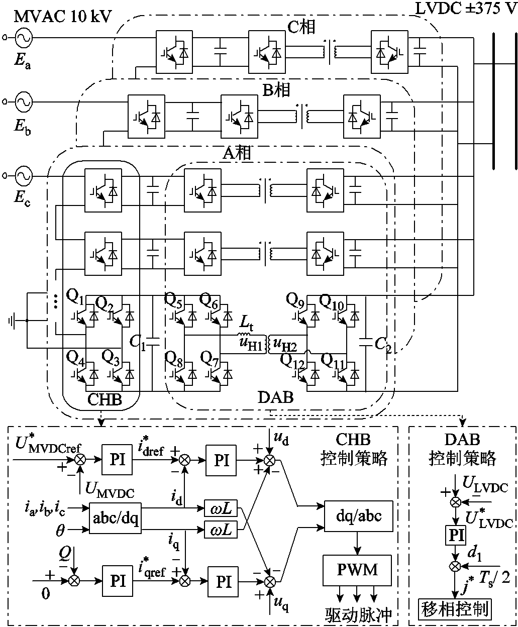
图2 CHB-PET的拓扑及控制策略
Fig.2 Topology and control strategy of CHB-PET
CHB-PET的输入级由CHB组成,CHB每相桥臂由全桥子模块串联而成,三相星形联结形成中性点后接地。CHB通常采用U/Q、P/Q和U/f控制,控制方式为双闭环控制。隔离级由双有源桥(Dual Active Bridge, DAB)组成。DAB由高压H桥和低压H桥通过高频变压器级联形成。低压H桥并联形成±375 V直流端口。DAB可采取电压控制或功率控制,实现功率双向流动。通过控制DAB高压侧与低压侧移相角决定功率流动方向,实现CHB-PET向±375 V直流电网供电或±375 V储能向CHB-PET反向送能等运行工况。
电池储能系统(Battery Energy Storage System, BESS)的拓扑结构及控制策略如图3所示。
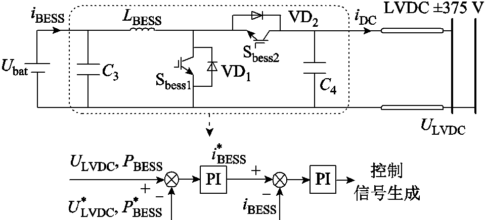
图3 电池储能系统拓扑及控制策略
Fig. 3 Topology and control strategy of BESS
±375 V储能换流器通常采用Buck-Boost换流器,采用定功率或定电压控制。直流微电网孤岛运行时,储能换流器常采用定电压控制以维持直流母线电压的稳定;CHB-PET并网运行时,储能换流器常采用定功率控制。
本文提出的基于CHB-PET与直流微电网协同控制的备用短引线故障检测及安全投入方案可分为三个阶段,分别是短引线故障隔离阶段、CHB-PET与直流微电网储能装置协同控制阶段(以下简称为协同控制阶段)和备用短引线故障检测及投入阶段。
CHB-PET与直流微电网协同控制策略如图4所示。短引线1故障后,FU1熔断,CHB闭锁,短引线1的故障隔离完成,阶段一结束,进入CHB-PET与直流微电网储能装置协同控制阶段(阶段二)。此时交流源向直流线路的功率传输终止,CHB-PET无法控制±375 V直流母线电压,因此储能换流器由稳态运行时的定功率控制模式切换为定电压控制模式,维持±375 V直流母线电压恒定[29-30],如图4点画线框所示。由于母线电压得到储能装置的支撑,可切换DAB由稳态运行时的±375 V直流电压控制模式为中压直流电容电压控制模式,通过DAB与储能装置的协同配合,保证DAB中压直流侧电容电压的稳定,为短引线故障检测奠定基础,如图4黄色虚线框所示。
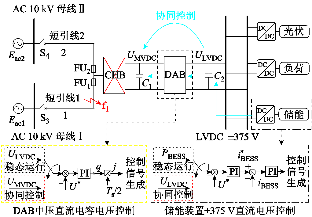
图4 CHB-PET与直流微电网协同控制策略
Fig.4 Schematic diagram of the collaborative control strategy of CHB-PET and DC microgrid
当通过协同控制使得CHB-PET中压直流电容和±375 V直流母线电压稳定后,解锁CHB,进入阶段三。控制CHB主动产生特征信号,向备用短引线注入特征电压。根据备用短引线在不同场景下的电气量特征差异,提出计及电流不平衡因子的故障检测判据,完成备用短引线的故障检测及安全投入。
2.2.1 特征信号的产生
在CHB解锁后,切换为U/f控制,向交流短引线2注入幅值频率可控的特征电压。图5所示为CHB-PET主动注入特征电压的原理示意图。
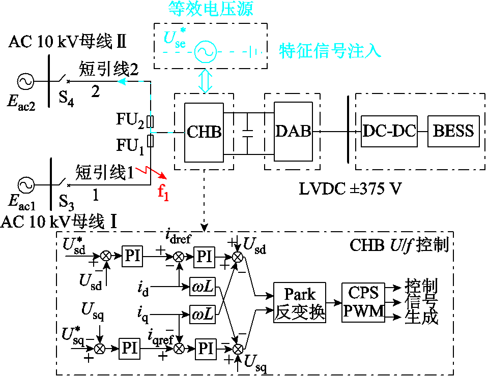
图5 主动注入特征电压原理示意示意图
Fig.5 Diagram of active injection characteristic voltage
特征电压的幅值选择应考虑故障检测和测量精度的要求以及电力电子装备的故障承受能力。特征电压幅值越大,对故障检测越有利,但幅值过大会导致特征电流较大,损坏电力电子装备;幅值过小可能导致测量精度下降。根据文献[31-32],特征电压幅值的选择范围通常在0.1~0.2(pu),本文选择20%的额定电压作为注入特征电压的幅值。
特征电压的频率选择应满足采样定理,同时应小于CHB的载波频率。在本文的研究对象中,保护装置的采样频率为2 kHz,CHB的载波频率为 3 kHz,根据文献[33-34],特征电压频率的选择范围通常在50~200 Hz。本文选择50 Hz作为特征电压的频率,保证特征信号的采样精度和信号注入的有效性[35]。
特征电压的注入时间选择主要考虑控制器的响应延时。CHB的U/f控制响应延时通常在10 ms以内[36]。根据文献[37-38],注入时间的选择范围通常在20~50 ms。本文选择特征电压的注入时间为30 ms。本文所提方案不同阶段的时序如图6所示。
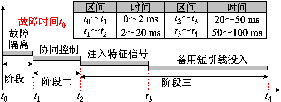
图6 所提方案阶段时序
Fig.6 Stage timing diagram of the proposed scheme
2.2.2 备用短引线电气量特征分析
在主动注入特征电压后,备用短引线电气量特征在不同场景下存在显著差异,分别分析备用短引线在无故障场景和存在故障场景下的电气量特征。
1)备用短引线无故障场景
如图5所示,若CHB-PET交流侧短引线1发生故障,而短引线2没有故障,CHB向短引线2注入特征电压后,特征电流幅值很小。
2)备用短引线存在故障场景
图7所示为交流短引线2存在故障时,注入特征电压后的故障电流示意图。不同故障类型下,交流短引线2的电压和电流的特征如下:
(1)单相接地故障:10 kV交流系统常采用不接地或经消弧线圈接地的接地方式。单相接地故障发生后,系统侧无故障回路,CHB三相采用星形接地的方式,CHB与故障点形成故障回路,CHB-PET可向故障点提供短路电流。
(2)两相短路和两相接地故障:特征电流三相不对称,故障相电流幅值较大。
(3)三相短路故障:特征电流仍三相对称,三相电流幅值很大。
综上所述,向短引线2注入特征电压后,可根据短引线2的三相电流差异判断是否存在故障。

图7 短引线2故障时故障电流示意图
Fig.7 Fault current when short lead line 2 is faulty
2.2.3 计及电流不平衡因子的故障检测判据
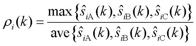
根据2.2.2节的分析,利用特征电流绝对值的积分值与特征电流不平衡因子构造故障检测判据。故障检测判据Siφ(k)的计算式为
 (1)
(1)
式中, 为第k个采样点对应的特征电流不平衡因子;
 为三相特征电流的积分值,下标i表示电流。
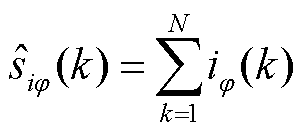
三相特征电流积分值表达式为
 (2)
(2)
式中,iφ(k)为第k个采样点对应的交流电流瞬时值;N为采样点个数。
特征电流不平衡因子的表达式为
 (3)
(3)
式中, 为第k个采样点对应的三相特征电流积分值的最大值;
 为三相特征电流积分值的平均值。
若备用短引线无故障,三相特征电流绝对值的积分值较小,特征电流不平衡因子约为1,因此故障检测判据较小;若备用短引线存在故障,三相特征电流绝对值的积分值较大,特征电流不平衡因子大于1,因此故障检测判据较大。当故障检测判据满足式(4)时,判定备用短引线存在故障。
 (4)
(4)
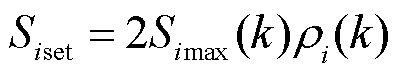
式中,Simax(k)为第k个采样点对应的三相电流故障检测判据的最大值,表达式见式(5);Siset为故障检测判据的整定值。
 (5)
(5)
式中,SiA(k)、SiB(k)、SiC(k)为第k个采样点对应的三相电流故障检测判据,由式(1)计算得到。
整定值Siset的计算方法是,备用短引线无故障时,在特征电压注入的结束时刻,三相电流积分值的最大值与电流不平衡因子相乘后再乘以可靠系数2得到,即
参照我国某10 kV含CHB-PET的柔性互联交直流微电网工程参数,在PSCAD/EMTDC仿真平台搭建如图1所示的直流电网拓扑,仿真参数见表1。
表1 交直流微电网系统及CHB-PET参数
Tab.1 Parameters of AC/DC microgrid system and CHB-PET
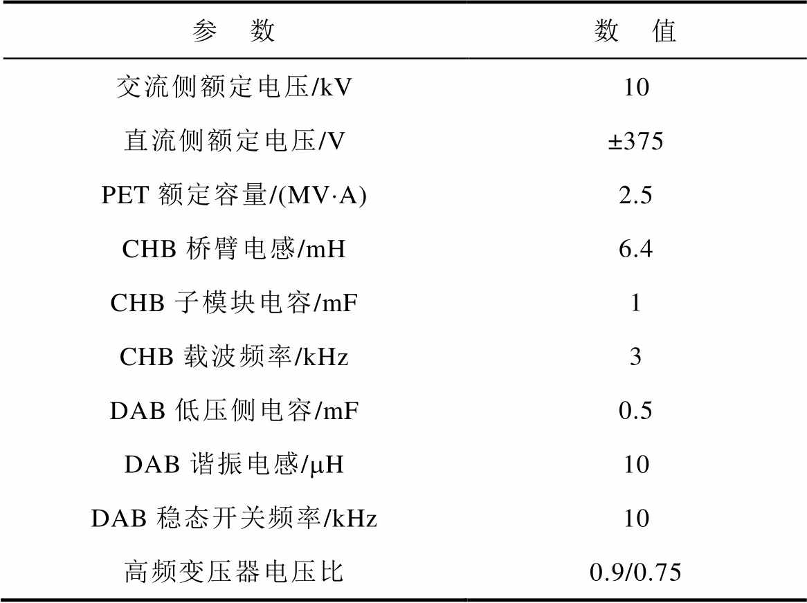
参 数数 值 交流侧额定电压/kV10 直流侧额定电压/V±375 PET额定容量/(MV×A)2.5 CHB桥臂电感/mH6.4 CHB子模块电容/mF1 CHB载波频率/kHz3 DAB低压侧电容/mF0.5 DAB谐振电感/mH10 DAB稳态开关频率/kHz10 高频变压器电压比0.9/0.75
3.1.1 短引线故障隔离及协同控制阶段(阶段一和阶段二)仿真验证
模拟短引线1于0 s发生金属性三相短路故障。故障后阶段一和阶段二对应的时间为0~20 ms。重点对比采用常规方案与协同控制方案时,直流母线电压和直流分支线电流能否保持稳定。
1)常规方案
未采取协同控制(即常规方案)时,±375 V直流母线电压和直流分支线电流如图8所示。电流的参考方向为母线指向线路。故障发生后±375 V母线电压迅速跌落,直流微电网各分支线的换流器电容会向直流母线放电,直流电流发生较大波动。
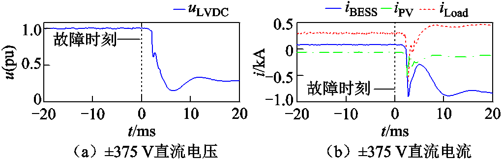
图8 未采取协同控制时直流电压和电流
Fig.8 DC voltage and current without cooperative control
2)协同控制方案
采取本文的协同控制时,±375 V直流电压、直流分支线电流和CHB-PET中压电容电压如图9所示。图9中,Δt1、Δt2、Δt3分别代表阶段一、二、三。
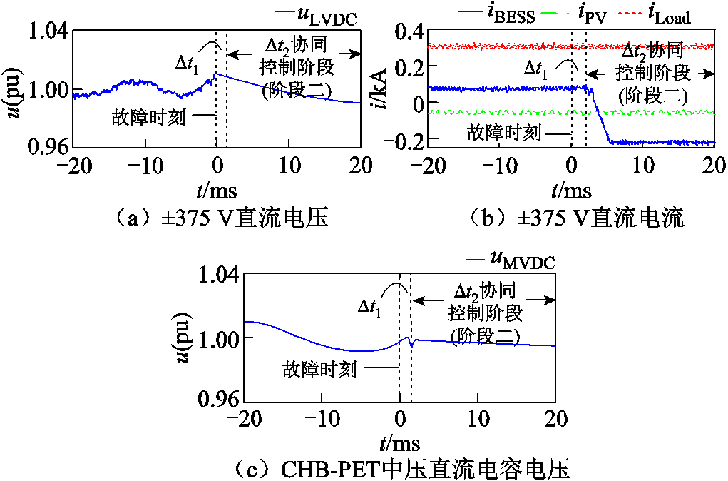
图9 采取协同控制时直流电压和电流
Fig.9 DC voltage and current with cooperative control
由图9可知,在协同控制策略下,±375 V直流电压和电流能够保持稳定。储能装置在故障发生前吸收功率,电流为正,故障发生后切换为定电压控制,电流为负。负荷和光伏支路电流几乎不受影响。
3.1.2 备用短引线故障检测及投入阶段(阶段三)仿真验证
阶段三的仿真验证分为备用短引线2无故障和存在故障两种情况。阶段三重点对比采用本文判据和对比判据在故障检测时间上的差异。
1)备用短引线2无故障
模拟短引线1在0 s时发生金属性三相短路故障。备用短引线2无故障。特征电压电流、故障检测判据及CHB-PET交直流侧电压电流如图10所示。
由图10a和图10b可知,短引线2无故障时,特征电压幅值达到指令值0.2(pu),特征电流较小。
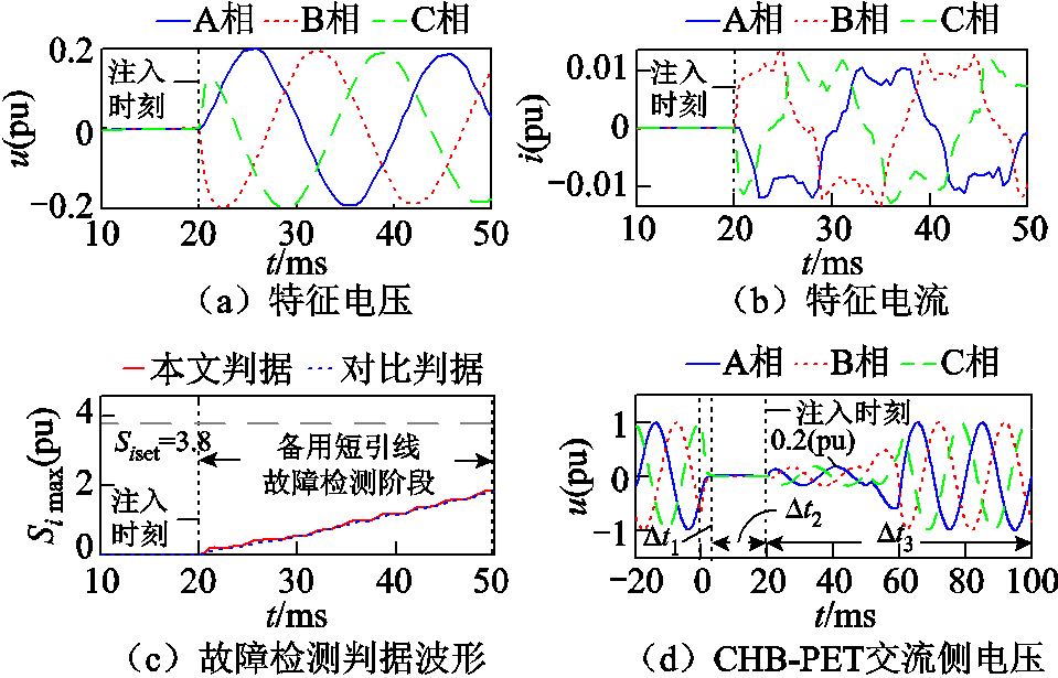

图10 短引线2无故障时电气量波形
Fig.10 Electric quantity waveforms when short lead 2 is fault-free
由图10c可知,特征电压注入的结束时刻 t=50 ms,电流不平衡因子约为1,Simax为1.9。因此故障检测判据的整定值可考虑1.9的2倍为3.8。对比判据的整定值为线路不存在故障时,t=50 ms时三相电流积分值最大值的2倍。两种故障检测方法的整定值相同。
由图10d、图10e、图10f可知,在所提方案的三个阶段,±375 V直流电压电流均能保持稳定。在判别备用交流短引线无故障后将其接入,交流电压恢复正常。
2)备用短引线2存在故障
模拟短引线2末端发生金属性和经过渡电阻A相接地故障。特征电压电流、故障检测判据及CHB-PET交直流侧电压电流如图11所示。
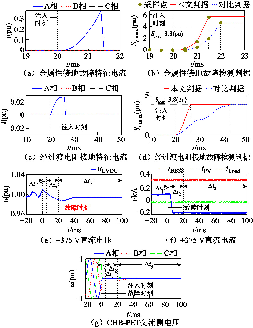
图11 短引线2存在故障时电气量波形
Fig.11 Electric quantity waveforms when short lead 2 is faulty
由图11b可知,在发生金属性A相接地故障时,注入特征电压1.5 ms后可识别出备用短引线存在故障。配电网中故障电流小于50 A时可视为高阻故 障[39],本文设置相间过渡电阻为200 W,接地过渡电阻为300 W,此时故障电流均在30 A(0.15(pu))以下。由图11d可知,在过渡电阻为300 W 的情况下,本文判据缩短了15 ms左右的检测时间。由图11e、图11f、图11g可知,在所提方案的三个阶段,±375 V直流电压电流均能保持稳定。在判别备用交流短引线存在故障后,CHB-PET闭锁,不再接入故障短引线。
模拟短引线2末端发生金属性和经过渡电阻三相短路、两相短路、两相接地故障,本文判据和对比判据所需的故障检测时间见表2。
表2 不同故障类型下故障检测时间
Tab.2 Fault detection time under different fault types
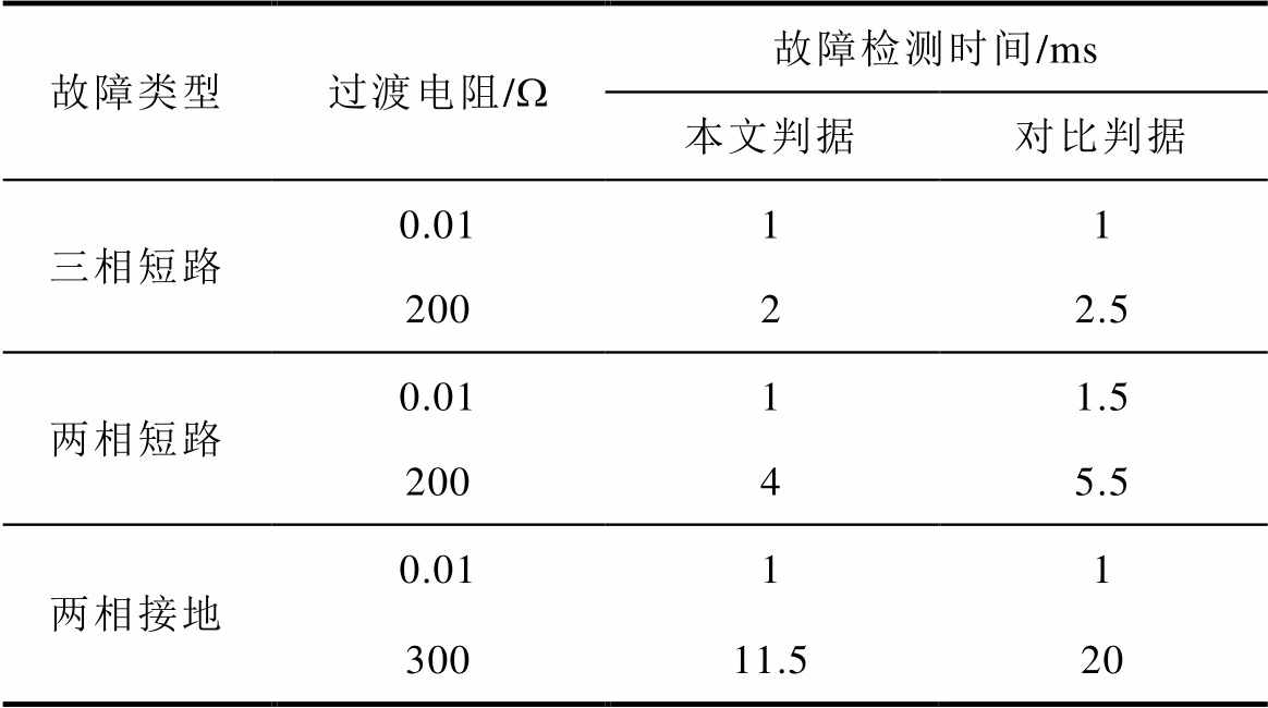
故障类型过渡电阻/W故障检测时间/ms 本文判据对比判据 三相短路0.0111 20022.5 两相短路0.0111.5 20045.5 两相接地0.0111 30011.520
由表2可知,在发生不同类型高阻故障的情况下,本文判据能够更快地完成故障检测。
在3.1节仿真验证的基础上,为进一步验证本文提出方案的可行性,构建了相应的半实物硬件在环实验平台,如图12所示。

图12 实验平台
Fig.12 Experimental platform
该实验平台主要由上海远宽能源科技有限公司生产的MT 8020实时仿真平台和MT 1070快速控制原型机(Rapid Control Prototyping, RCP)搭建而成。MT 8020对应主电路拓扑,将模拟信号输出给控制器MT1070RCP,将输出数字信号控制主电路中信号的开断。两者之间通过DB37线缆交换信号,实现HIL测试系统。本文提出的控制策略对应的算法装载在MT 1070中,主电路拓扑装载于MT 8020,用示波器观察输出波形。由于MT 1070输出通道数量的限制,重点针对协同控制策略进行实验验证。
3.2.1 常规方案实验验证
模拟短引线1发生故障,未采取协同控制时,±375 V直流母线电压和分支线电流如图13所示。
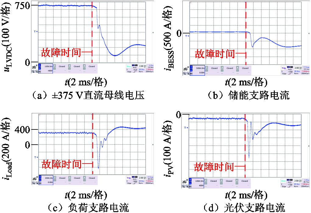
图13 未采取协同控制下电气量波形
Fig.13 Electric quantity waveforms without cooperative control
由图13可知,短引线1故障发生后,±375 V直流母线电压与直流分支线电流均发生较大波动,与3.1.1节仿真结果一致。
3.2.2 协同控制方案实验验证
模拟短引线1发生故障,采取协同控制(本文方案)时,±375 V直流母线电压和电流如图14所示。
由图14可知,在方案的三个阶段,±375 V母线电压较为稳定,储能支路电流在故障后反向,为直流电微网提供功率支撑并维持直流母线电压稳定。在判别备用短引线2安全后,切换为吸收功率的运行工况。负荷和光伏支路电流几乎不受影响,与3.1.1节仿真结果一致。

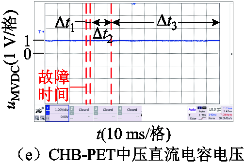
图14 协同控制下电气量波形
Fig.14 Electric quantity waveforms under cooperative control
本文提出的方案在不同场景下的仿真验证和实验验证得出了一致的结果,证实了仿真模型的准确性与本文提出方案的可行性。
本文基于CHB-PET交流短引线互为备用接入不同母线段的场景,针对常规方案在备用短引线投入之前无法判断其是否安全的问题,提出了一种基于CHB-PET与直流微电网储能装置协同控制并主动注入特征电压的备用短引线故障检测及安全投入方案。方案包括三个阶段:短引线故障隔离阶段、协同控制阶段和备用短引线故障检测及投入阶段。主要结论如下:
1)在整体方案上,利用CHB-PET向备用短引线注入特征电压,根据备用短引线在不同场景下电气量特征的差异,可准确地检测备用短引线是否存在故障,实现了备用短引线的安全投入。
2)在所提方案的三个阶段,利用CHB-PET与直流微电网储能装置的协同控制,保证了交流短引线故障后,直流微电网各装备的正常运行,有利于故障后的快速恢复。
3)在备用短引线故障检测阶段,利用特征电流不平衡因子和电流积分值的乘积构造故障检测判据,相较于直接利用电流积分值,缩短了高阻故障下的故障检测时间,提高了保护动作速度。
参考文献
[1] 高范强, 李子欣, 李耀华, 等. 面向交直流混合配电应用的10 kV-3 MV·A四端口电力电子变压器[J]. 电工技术学报, 2021, 36(16): 3331-3341.
Gao Fanqiang, Li Zixin, Li Yaohua, et al. 10 kV- 3 MV·A four-port power electronic transformer for AC-DC hybrid power distribution applications[J]. Transactions of China Electrotechnical Society, 2021, 36(16): 3331-3341.
[2] 李勇, 凌锋, 乔学博, 等. 基于网侧资源协调的自储能柔性互联配电系统日前-日内优化[J]. 电工技术学报, 2024, 39(3): 758-773, 923.
Li Yong, Ling Feng, Qiao Xuebo, et al. Day-ahead and intra-day optimization of flexible interconnected distribution system with self-energy storage based on the grid-side resource coordination[J]. Transactions of China Electrotechnical Society, 2024, 39(3): 758- 773, 923.
[3] 何晓坤, 胡仁杰, 陈武. 一种适用于新能源中压直流汇集的无环流零电流软开关三电平谐振式复合全桥变换器[J]. 电工技术学报, 2023, 38(19): 5274-5287.
He Xiaokun, Hu Renjie, Chen Wu. A novel circulating current free zero current switching three-level resonant composite full bridge converter for new energy medium voltage DC collection system[J]. Transactions of China Electrotechnical Society, 2023, 38(19): 5274-5287.
[4] 徐展鹏, 梁远升, 李海锋, 等. 柔性互联配电网故障恢复的云边协同优化算法[J]. 电力系统自动化, 2023, 47(18): 171-184.
Xu Zhanpeng, Liang Yuansheng, Li Haifeng, et al. Cloud-edge collaborative optimization algorithm for fault restoration of flexible interconnected distribution network[J]. Automation of Electric Power Systems, 2023, 47(18): 171-184.
[5] 王怡, 杨知方, 余娟, 等. 考虑可靠性需求的配电网多种设备统一优化配置[J]. 电工技术学报, 2023, 38(24): 6727-6743.
Wang Yi, Yang Zhifang, Yu Juan, et al. A unified optimal placement method for multiple types of devices in distribution networks considering reliability demand[J]. Transactions of China Electrotechnical Society, 2023, 38(24): 6727-6743.
[6] 张博, 马梓耀, 王辰, 等. 含光储充一体化电站的城市交直流混合配电网韧性提升策略[J]. 电力系统自动化, 2023, 47(12): 28-37.
Zhang Bo, Ma Ziyao, Wang Chen, et al. Resilience improvement strategy for urban AC/DC hybrid distribution network with photovoltaic-storage-charging integrated station[J]. Automation of Electric Power Systems, 2023, 47(12): 28-37.
[7] 许寅, 和敬涵, 王颖, 等. 韧性背景下的配网故障恢复研究综述及展望[J]. 电工技术学报, 2019, 34(16): 3416-3429.
Xu Yin, He Jinghan, Wang Ying, et al. A review on distribution system restoration for resilience enhancement[J]. Transactions of China Electrotechnical Society, 2019, 34(16): 3416-3429.
[8] 马伟明. 关于电工学科前沿技术发展的若干思考[J]. 电工技术学报, 2021, 36(22): 4627-4636.
Ma Weiming. Thoughts on the development of frontier technology in electrical engineering[J]. Transactions of China Electrotechnical Society, 2021, 36(22): 4627-4636.
[9] Chen Zhengyu, Yu Zhanqing, Zhang Xiangyu, et al. Analysis and experiments for IGBT, IEGT, and IGCT in hybrid DC circuit breaker[J]. IEEE Transactions on Industrial Electronics, 2018, 65(4): 2883-2892.
[10] 赵楠, 郑泽东, 刘建伟, 等. 级联H桥变换器IGBT开路故障分析与冗余方法研究[J]. 电工技术学报, 2023, 38(6): 1608-1619.
Zhao Nan, Zheng Zedong, Liu Jianwei, et al. IGBT open-circuit fault analysis and fault-tolerant method for cascaded H-bridge converter[J]. Transactions of China Electrotechnical Society, 2023, 38(6): 1608-1619.
[11] Zhang Fan, Mu Longhua, Guo Wenming. An integrated wide-area protection scheme for active distribution networks based on fault components principle[J]. IEEE Transactions on Smart Grid, 2019, 10(1): 392- 402.
[12] Muda H, Jena P. Superimposed adaptive sequence current based microgrid protection: a new tech- nique[J]. IEEE Transactions on Power Delivery, 2017, 32(2): 757-767.
[13] Zhang Zhihua, Crossley P, Xu Bingyin, et al. Sequence current component and its power direction- based improved protection for spot network with DERs[J]. IET Generation, Transmission & Dis- tribution, 2017, 11(7): 1634-1644.
[14] Zhang Qian, Qi Zhenxing, Cui Puyi, et al. Detection of single-phase-to-ground faults in distribution networks based on gramian angular field and improved convolutional neural networks[J]. Electric Power Systems Research, 2023, 221: 109501.
[15] Wang Yangkun, Zhang Feng, Zhang Xueheng, et al. Series AC arc fault detection method based on hybrid time and frequency analysis and fully connected neural network[J]. IEEE Transactions on Industrial Informatics, 2019, 15(12): 6210-6219.
[16] Wang Ting, Hussain K S T, Song Guobing, et al. Adaptive single-phase/three-phase reclosing scheme for transmission lines in passive network supplied by MMC-HVDC[J]. International Journal of Electrical Power & Energy Systems, 2019, 113: 597-606.
[17] 陈福锋, 杨黎明, 宋国兵, 等. 面向主动探测式保护的变流器正交控制策略[J]. 电力自动化设备, 2024, 44(3): 75-81.
Chen Fufeng, Yang Liming, Song Guobing, et al. Orthogonal control strategy of converter for active detection protection[J]. Electric Power Automation Equipment, 2024, 44(3): 75-81.
[18] 汤耀景, 孔凡坊, 宋国兵, 等. 分布式光伏并网线路的相间故障主动探测式保护原理[J]. 供用电, 2023, 40(1): 41-48.
Tang Yaojing, Kong Fanfang, Song Guobing, et al. Active detection protection method for interphase fault of distributed photovoltaic grid-connected line[J]. Distribution & Utilization, 2023, 40(1): 41-48.
[19] 宋国兵, 王婷, 张保会, 等. 利用电力电子装置的探测式故障识别技术分析与展望[J]. 电力系统自动化, 2020, 44(20): 173-183.
Song Guobing, Wang Ting, Zhang Baohui, et al. Analysis and prospect of detective fault identification technologies using power electronic device[J]. Automation of Electric Power Systems, 2020, 44(20): 173-183.
[20] 戴志辉, 吴桐, 何静远, 等. 基于控保协同的有源配网主动注入式保护方法[J]. 电力系统保护与控制, 2024, 52(3): 94-103.
Dai Zhihui, Wu Tong, He Jingyuan, et al. An active distribution network active injection protection method based on control-protection coordination[J]. Power System Protection and Control, 2024, 52(3): 94-103.
[21] 方重凯, 牟龙华, 欧锐, 等. 基于控保协同的微电网注入式保护方法研究[J]. 中国电机工程学报, 2023, 43(9): 3389-3401.
Fang Chongkai, Mu Longhua, Ou Rui, et al. Research on control-protection coordination based on injection protect scheme of microgrid[J]. Proceedings of the CSEE, 2023, 43(9): 3389-3401.
[22] 康涛, 翁汉琍, 林湘宁, 等. 考虑储能系统控保协同体系的光伏场站送出线路突变量选相能力恢复策略[J]. 中国电机工程学报, 2024, 44(11): 4273- 4285.
Kang Tao, Weng Hanli, Lin Xiangning, et al. Phase selection capacity recovery strategy for transmission line of photovoltaic station based on the control and insurance cooperative of energy storage system[J]. Proceedings of the CSEE, 2024, 44(11): 4273-4285.
[23] 褚旭, 刘琦, 吕昊泽, 等. 基于控保协同海底观测网供电系统保护方案[J]. 电工技术学报, 2023, 38(7): 1780-1792.
Chu Xu, Liu Qi, Lü Haoze, et al. Protection scheme for subsea observatory power supply system based on control and protection coordination[J]. Transactions of China Electrotechnical Society, 2023, 38(7): 1780- 1792.
[24] Liu Haiyang, Ling Xiaobo, Zhu Yifan, et al. Optimization of backup power automatic switching strategy in the distribution network with distributed photovoltaics[C]//2021 IEEE/IAS Industrial and Commercial Power System Asia (I&CPS Asia), Chengdu, China, 2021: 1133-1137.
[25] Zhang Dongying, Guo Yun, Zhang Xu, et al. A complete analytical method for fault diagnosis of power grid considering operation information of backup automatic switch[C]//2019 IEEE Sustainable Power and Energy Conference (iSPEC), Beijing, China, 2019: 1722-1727.
[26] 陈志峰, 沈娜, 王玕, 等. 高渗透率水电接入的变电站备自投逻辑优化研究[J]. 电力系统保护与控制, 2023, 51(4): 157-164.
Chen Zhifeng, Shen Na, Wang Gan, et al. Logic optimization of a transformer substation busbar automatic transfer switch with high penetration of hydropower[J]. Power System Protection and Control, 2023, 51(4): 157-164.
[27] Chen Yang, Li Lei, Lian Hongbo, et al. Analysis of the impact of MW-level grid-connected photovoltaic power station on backup automatic switch in distribution network[C]//2019 IEEE Sustainable Power and Energy Conference (iSPEC), Beijing, China, 2019: 2663-2669.
[28] Yin Chaoyong, Li Gang, Xu Biao, et al. Principle and implementation of remote backup power automatic throw-in in serial power grid connection with multiple-communication modes[C]//2022 Asia Power and Electrical Technology Conference (APET), Shanghai, China, 2022: 138-142.
[29] 李培强, 段克会, 董彦婷, 等. 含分布式混合储能系统的光伏直流微网能量管理策略[J]. 电力系统保护与控制, 2017, 45(13): 42-48.
Li Peiqiang, Duan Kehui, Dong Yanting, et al. Energy management strategy for photovoltaic DC microgrid with distributed hybrid energy storage system[J]. Power System Protection and Control, 2017, 45(13): 42-48.
[30] 米阳, 宋根新, 蔡杭谊, 等. 基于分段下垂的交直流混合微电网自主协调控制[J]. 电网技术, 2018, 42(12): 3941-3950.
Mi Yang, Song Genxin, Cai Hangyi, et al. Autonomous coordinated control of hybrid AC/DC microgrids based on segmented droop[J]. Power System Technology, 2018, 42(12): 3941-3950.
[31] 郑涛, 王赟鹏, 马家璇, 等. 基于特征电压注入的UPFC接入线路三相自适应重合闸方案[J]. 电力系统自动化, 2021, 45(5): 152-158.
Zheng Tao, Wang Yunpeng, Ma Jiaxuan, et al. Three-phase adaptive reclosure scheme based on characteristic voltage injection for transmission line equipped with unified power flow controller[J]. Automation of Electric Power Systems, 2021, 45(5): 152-158.
[32] 宋国兵, 侯俊杰, 郭冰. 基于主动探测式的柔性直流电网纵联保护[J]. 电网技术, 2020, 44(10): 4001-4010.
Song Guobing, Hou Junjie, Guo Bing. Pilot protection of flexible DC grid based on active detection[J]. Power System Technology, 2020, 44(10): 4001-4010.
[33] 宋国兵, 王婷, 张晨浩, 等. 利用全桥MMC注入特征信号的直流自适应重合闸方法[J]. 电网技术, 2019, 43(1): 149-156.
Song Guobing, Wang Ting, Zhang Chenhao, et al. Adaptive auto-reclosing of DC line based on characteristic signal injection with FB-MMC[J]. Power System Technology, 2019, 43(1): 149-156.
[34] 宋国兵, 侯俊杰, 郭冰. 基于主动探测式的混合MMC直流输电系统单端量故障定位[J]. 电网技术, 2021, 45(2): 730-740.
Song Guobing, Hou Junjie, Guo Bing. Single-ended fault location of hybrid MMC-HVDC system based on active detection[J]. Power System Technology, 2021, 45(2): 730-740.
[35] 陈福锋, 杨黎明, 宋国兵, 等. 主动探测式保护关键技术概述及展望[J]. 电力系统保护与控制, 2023, 51(15): 175-186.
Chen Fufeng, Yang Liming, Song Guobing, et al. Overview and prospect of key technologies for active detection protection[J]. Power System Protection and Control, 2023, 51(15): 175-186.
[36] 黄海宏, 颜碧琛, 王海欣. 并联级联H桥电源电流跟踪优化与环流抑制的模型预测控制[J]. 电工技术学报, 2023, 38(16): 4376-4390.
Huang Haihong, Yan Bichen, Wang Haixin. Model predictive control of current tracking optimization and circulating current suppression for multi-parallel cascaded H-bridge power supplies[J]. Transactions of China Electrotechnical Society, 2023, 38(16): 4376- 4390.
[37] 徐瑞东, 常仲学, 宋国兵, 等. 注入探测信号的直流配电网接地故障识别方法[J]. 电网技术, 2021, 45(11): 4269-4276.
Xu Ruidong, Chang Zhongxue, Song Guobing, et al. Grounding fault identification method for DC distribution network based on detection signal injection[J]. Power System Technology, 2021, 45(11): 4269-4276.
[38] Luo Xunhua, Deng Zhiming, Wu Jingyang, et al. Fault nature identification and location scheme for distribution network based on active injection from IIDG[J]. International Journal of Electrical Power & Energy Systems, 2024, 156: 109706.
[39] 徐丙垠, 李天友, 薛永端. 配电网继电保护与自动化[M]. 北京: 中国电力出版社, 2017.
Abstract Power electronic transformer with cascaded H-bridge (CHB-PET) can realize the flexible interconnection of AC/DC microgrid and renewable energy sources such as energy storage devices and DC loads. In a practical project, CHB-PET is connected to different bus segments through two short leads that are standby for each other. Considering the fault occurring ACside of CHB-PET, the spare short lead needs to be put into operation quickly to realize the rapid recovery of power supply.However, the conventional scheme cannot distinguish whether there is a fault before the spare short lead is put into operation, and there is a risk of connecting the faulty short lead.To solve this problem, this paper proposes a scheme based on the cooperative control of CHB-PET and DC microgrid, which achieves safe input of short leads by actively injecting characteristic voltage.
Firstly,CHB is blocked to achieve fault isolation after fault occurring. The energy storage device is switched to DC voltage control mode, maintaining the DC bus voltage and ensuring the normal operation of DC microgrid load and other equipment. Secondly, CHB is unlocked and switched to the U/f control. CHB-PET can inject characteristic voltage into the spare line to detect whether there is a fault point in the line.Furthermore, a fault detection method considering the current imbalance factor is proposed to reduce the time required for fault detection, so as to realize the rapid and safe investment of spare short lead.
The verification results on PSCAD/EMTDC simulation platform show that the scheme based on characteristic voltage injection can give accurate detection results when the spare line is fault-free. When three-phase fault, phase-phase fault, double-phase to ground fault and single-phase to ground fault occur in the spare line, the transition resistance of the phase-to-phase fault is 200 W, and the transition resistance of the ground fault is 300 W. The proposed scheme can also give accurate detection results. Through the simulation verification and experimental verification of the proposed scheme in different scenarios, the consistent results are obtained, which confirms the accuracy of the simulation model and the feasibility of the proposed scheme.
Through the simulation analysis, the following conclusions can be drawn: (1) The scheme uses the CHB-PET ontology to inject characteristic voltage with controlled amplitude and frequency into the standby line. According to the difference of electrical characteristics of the standby line in different scenarios, proposed scheme can accurately detect whether there is a fault in the standby line. (2) In three stages of the proposed scheme, the collaborative control of CHB-PET and DC microgrid energy storage device is used to ensure the normal operation of each equipment in the DC microgrid after the AC short lead fault, which is conducive to the rapid recovery after the fault. (3) In the fault detection stage of spare short lead, the fault detection criterion is constructed by using the product of the characteristic current imbalance factor and the current integral value. Compared with the direct use of the current integral value, the fault detection time under high resistance fault is reduced and the protection action speed is improved.
Keywords:Fault detection, power electronic transformer with cascaded H-bridge, active injection, cooperative control
中图分类号:TM771
DOI: 10.19595/j.cnki.1000-6753.tces.240273
国家自然科学基金联合基金资助项目(U2166205)。
收稿日期 2024-02-19
改稿日期 2024-04-19
郑 涛 男,1975年生,教授,博士生导师,研究方向为电力系统自动化及继电保护。
E-mail: zhengtao_sf@126.com(通信作者)
郭勇帆 男,1995年生,博士研究生,研究方向为新能源电力系统继电保护。
E-mail: 245494938@qq.com
(编辑 郭丽军)