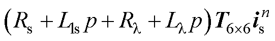
图1 定子分段直线感应电机拓扑、绕组及供电结构
Fig.1 The topology, winding and power supply structure of the segmented linear induction motor
摘要 定子分段直线感应电机在超高速电磁推进领域具有较好的应用前景,然而多相直线感应电机定子与动子耦合程度快速时变、供电切换晶闸管开关电流过零关断、供电电缆阻抗随动子位置变化等非线性特性显著,导致现有建模方法难以准确实时地模拟系统电磁暂态过程。该文将直线感应电机系统依据能量转换特性划分为有效转换、无效转换和电源三部分,采用多相电机定子空间矢量解耦建模和虚拟动子磁链方法,实现了晶闸管与直线电机、电机定子与动子之间的解耦,并建立了数学模型。硬件在环实验结果表明,数学模型无迭代实时运算步长低至500 ns,原理样机实验结果表明,数学模型与物理实验误差小于7%,验证了数学模型的快速性和准确性,研究成果可为超高速直线感应电机推进系统高性能控制提供建模基础。
关键词:分段供电 多相直线感应电机 晶闸管开关 非线性特性 实时模型
长定子直线感应电机因其动子质量轻、结构简单等优点,在电磁推进高速地面试验设施(简称电磁橇)、航天电磁发射、超高速交通等领域具有较好的应用前景[1-2],目前公开报道长定子直线感应电机最高推进速度已到达1030 km/h。高速直线感应电机通常采用长定子分段供电拓扑,直线电机分段结构、供电切换晶闸管非线性特性、供电电缆阻抗长度变化等因素导致现有建模方法无法准确实时模拟系统电磁暂态过程[3-4],难以实现系统高性能控制。
现有高速直线电机数学建模方法主要有场路联合运算数学模型和集总参数等效电路数学模型。场路联合运算数学模型通过电磁场有限元和电路迭代运算,可实现系统电磁暂态特性精确模拟。该方法可为直线电机驱动系统提供精确的仿真结果,但其运算量大、时间长,无法实现实时运算[5-6]。集总参数等效电路数学模型具有效率高的优点,但存在直线电机非线性特性难以准确表征的问题[7]。现有文献已开展了直线电机参数不对称规律、边端效应、定子与动子非线性耦合特性等方面的研究[8]。文献[9]采用磁动势理论分析了直线电机定子互感不对称规律,文献[10]建立了考虑动子等效绕组不对称分布的数学模型。针对直线电机边端效应,文献[11-12]分析了直线电机的静态和动态纵向边端效应,并研究其对等效电路参数的影响。文献[13-14]在求解长初级双边直线感应电机气隙磁场解析解的基础上,推导出考虑纵向动态端部效应的解析表达式。对于分段供电直线电机定子与动子时变耦合关系建模,文献[15]提出了基于串联分段供电条件下定子与动子互感不变的原则建立直线感应电机T型等效电路模型。文献[16-19]通过引入时变次级耦合因子对全耦合时互感参数进行修正,建立了单元电机的数学模型并推导不同供电模式下的电机模型,但是未考虑供电切换影响。文献[20]分别建立正常模态、并联模态及错位模态下的电机模型,并通过模型之间的切换模拟供电切换时的暂态特性,但该方法模态较多导致较难实现多相电机实时运算。综上所述,现有直线电机建模方法难以同时满足直线电机非线性特性表征的快速性和准确性需求。
本文将直线感应电机推进系统依据能量转换特性划分为有效转换、无效转换和电源三部分,采用多相电机定子空间矢量解耦建模和虚拟动子磁链方法,提出分段供电直线感应电机推进系统非线性特性解耦建模方法,为系统高性能控制提供建模基础。
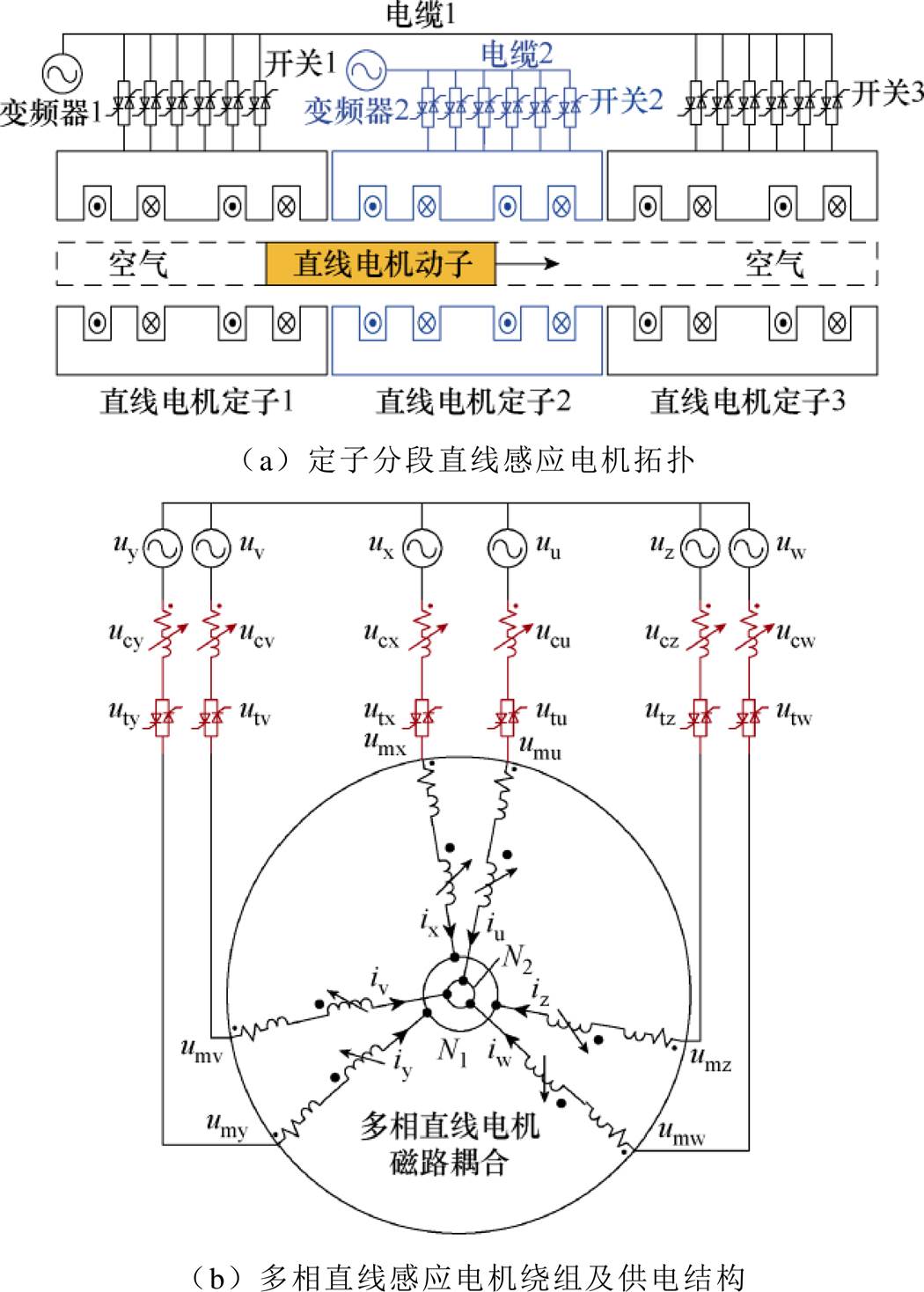
定子分段直线感应电机拓扑、绕组及供电结构如图1所示,图1a为定子分段直线感应电机拓扑,由直线电机定子、动子、晶闸管开关、变频器和电缆组成,依据动子位置控制晶闸管开通和关断实现定子分段供电。图1b为多相直线感应电机绕组及供电结构,直线电机采用双Y移30°绕组结构,图1将行波磁场等效为圆形磁场。直线电机供电结构为变频器输出电压经过长距离电缆和晶闸管开关对定子各相绕组供电。供电切换时晶闸管电流过零关断、电缆阻抗随动子位置变化、多相直线感应电机定子与动子耦合特性快速时变等非线性特性给实时数学建模带来较大挑战。本文所研究的直线电机为长定子直线感应电机,在高速运行时纵向边端效应对电机性能的影响不明显[21],且直线电机边端效应建模通常采用等效电路参数修正法[22],对实时运算也影响较小,因此本文所研究的实时建模方法暂不考虑边端效应影响。
图1 定子分段直线感应电机拓扑、绕组及供电结构
Fig.1 The topology, winding and power supply structure of the segmented linear induction motor
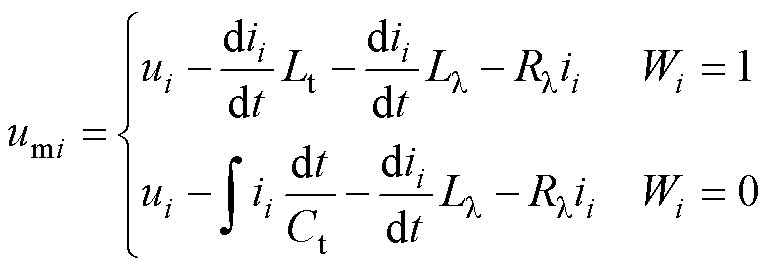
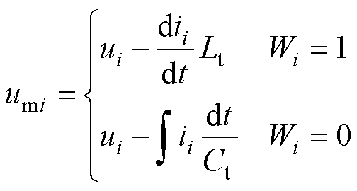
图2为定子分段直线感应电机推进系统非线性特性分析,图2a为直线感应电机单相绕组供电等效电路,为了实现系统实时运算,晶闸管通常采用LC开关模型[23-25],开通等效为电感,关断等效为阻容,供电电缆长度变化等效为可变阻感负载。直线感应电机单相绕组供电电压为
 (1)
(1)
式中,Wi为任意一相晶闸管导通状态,导通时Wi=1、关断时Wi=0;ii、umi分别为任意一相电机绕组电流和实际供电电压;ui为任意一相电源供电电压,下标i=u, v, w, x, y, z代表6相;Lt为晶闸管导通时等效电感;Ct为晶闸管关断时等效电容;Ll 和Rl分别为供电电缆等效可变电感和电阻,随着动子位置变化而变化。由式(1)可知,直线感应电机和晶闸管都为电流源特性,当电缆长度增加,阻抗越来越大时,电感电压微分项易引起系统运算不收敛。
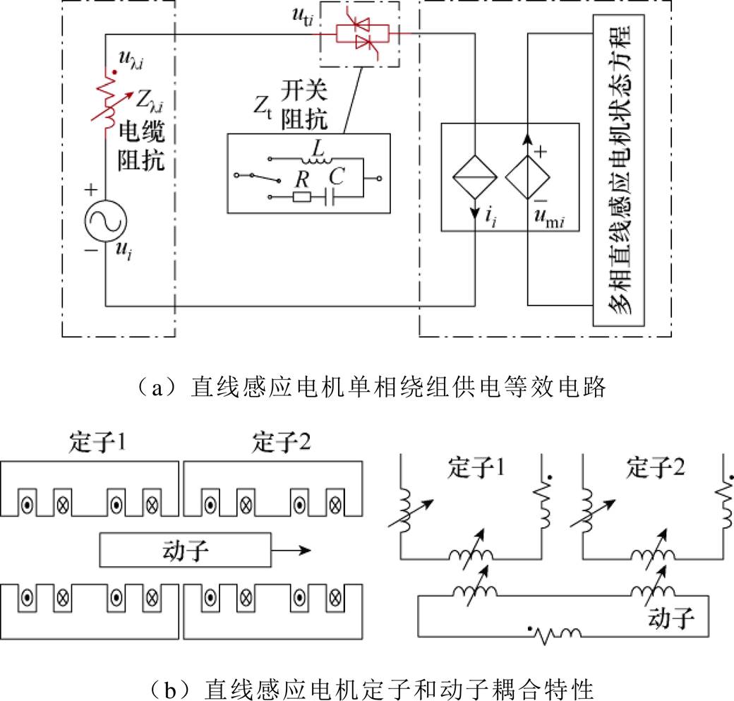
图2 定子分段直线感应电机推进系统非线性特性分析
Fig.2 Nonlinear analysis of linear induction motor propulsion system with segmented stator
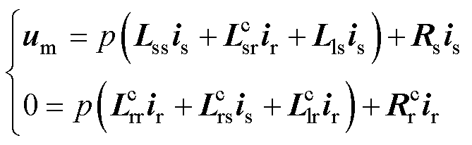
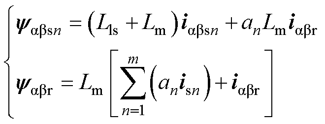
图2b为直线感应电机定子与动子之间耦合时变特性,当动子快速移动时,定子与动子覆盖比例快速时变,状态方程为
 (2)
(2)
其中
式中, 、
、 、
、 、
、 、
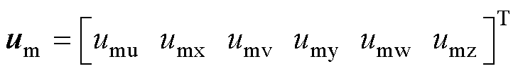
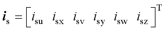
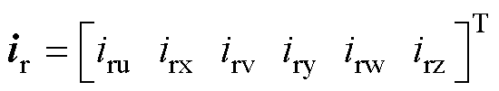
、 分别为电机动子自感、定子与动子互感、动子与定子互感、动子电阻、动子漏感矩阵,=,上标c代表参数具有非线性快速时变特性;Lss、Lls、Rs分别为定子自感、定子漏感、定子电阻矩阵;p为微分算子;is和ir分别为6相定子和动子电流。
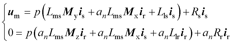
定义an为定子被动子覆盖比例,由式(2)可推导出式(3),由于an具有多个连续不可导点,数学模型在连续不可导点会存在数值运算发散问题。
 (3)
(3)
式中,an为定子被动子覆盖比例;Mx为定子与动子互感常系数矩阵;My和Mz分别为定子和动子自感常系数矩阵;Lls、Llr和Lms分别为电机各相定子漏感、动子漏感和自感;Rs和Rr分别为电机定子电阻和动子电阻。
因此,针对定子分段直线感应电机推进系统,需研究晶闸管切换过程、动子进入和离开定子段等工况下系统电磁暂态特性,需提出解耦建模方法并解决非线性特性的导致数学模型运算发散问题。
对于双Y移30°绕组多相旋转电机,空间矢量解耦变换方法将电机输入能量划分为1, 3, 5次空间,1次空间为有效机电能量转换,3次和5次空间属于谐波空间,为无效机电能量转换部分,有
 (4)
(4)
多相旋转电机经空间矢量解耦变换后电压和电流方程为
 (5)
(5)
 (6)
(6)
 (7)
(7)
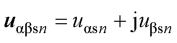
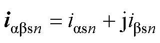
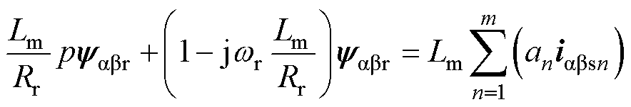
式中,uabs、iabs、iabr分别为ab 坐标系下定子电压、定子电流和动子电流;Lm为励磁电感;Lr为动子电感;wr为动子机械角速度;j为虚数;uz和iz分别为z空间定子电压和定子电流;uo和io分别为o空间定子电压和定子电流。
由式(5)~式(7)可知,Lm仅分布于式(5),Lls分布于式(6)和式(7),因此Lm被投影至1次空间为有效机电能量转换,漏感Lls被投影至3次和5次空间为无效机电能量转换。
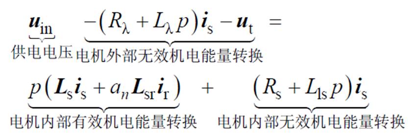
长定子直线感应电机与旋转电机差别较大,主要体现在两个方面。首先,定子和动子之间互感快速时变,也就是电机内部有效和无效机电能量转换部分快速时变。其次,动子位置变化引起供电电缆阻抗变化,电机外部无效机电能量转换部分发生变化。单个定子段直线感应电机推进系统状态方程为
 (8)
(8)
式中,uin为供电电压;ut为晶闸管电压。uin经过长距离电缆和晶闸管开关对电机各相绕组供电,因此ut和电缆压降为电机外部无效机电能量转换部分,定子漏感和定子电阻为电机内部无效机电能量转换部分,气隙磁链为电机内部有效机电能量转换部分。
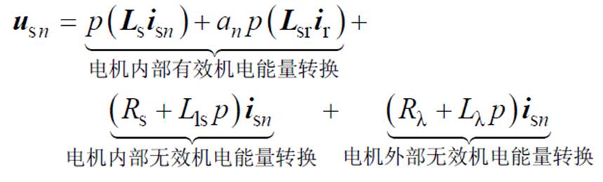
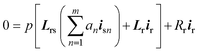
为了解决第1节所分析系统运算发散问题,提出了定子分段直线感应电机推进系统解耦建模方法,如图3所示,相对传统方法有两点改进:①对于直线感应电机定子,将电缆压降移入电机漏感部分,视为定子无效机电能量转换部分,可有效避免式(1)中微分项导致的运算发散问题。②对于直线感应电机动子,不同于传统方法式(3),本文虚拟出动子无效机电能量转换部分,提出了虚拟动子磁链方法。从动子角度看直线感应电机定子与动子之间互感为常数,覆盖比例变化等效为磁链占比变化,避免系数an在不可导点状态方程运算的发散问题。第n个定子段的直线感应电机解耦建模方法定子和动子状态方程分别为
 (9)
(9)
 (10)
(10)
式中,Ls、Lr为电机定子和动子电感矩阵;Lsr=Lrs为互感矩阵;usn、isn为第n个定子段电压和电流;m为定子段数量。
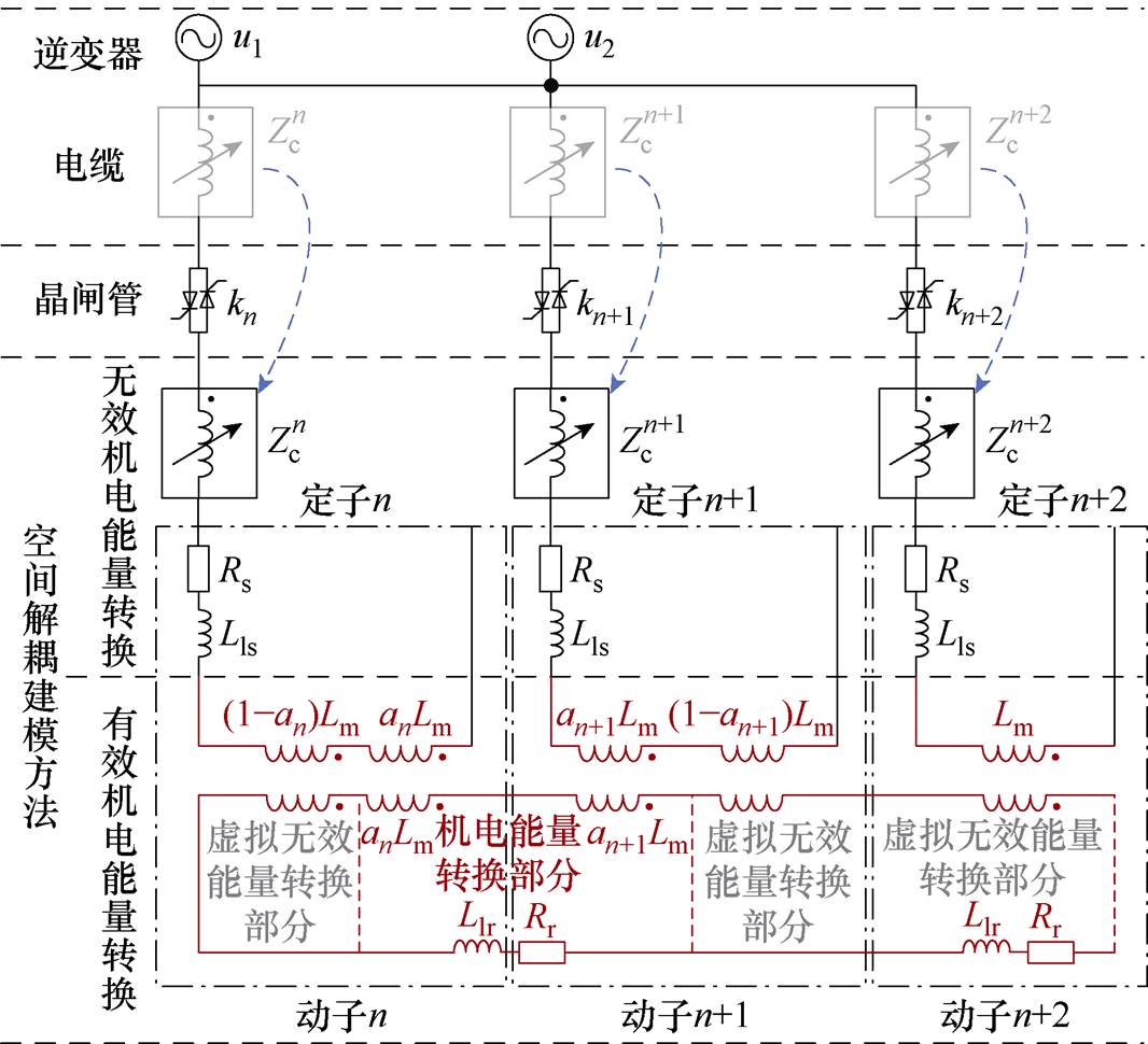
图3 定子分段直线感应电机推进系统解耦建模方法
Fig.3 Decoupled modeling method of linear induction motor propulsion system with segmented stator
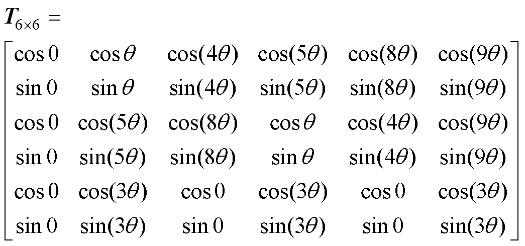
将式(9)和式(10)定子和动子状态方程两边同时乘以T6×6解耦变换矩阵,可得到解耦变换后定子和动子状态方程

 (11)
(11)
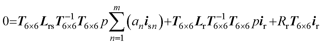 (12)
(12)
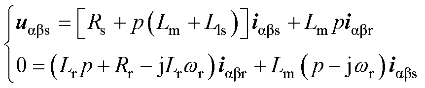
解耦变化后电机定子与动子1次空间状态方程复数表达式如式(13)和式(14)所示,该部分为ab 坐标系下直线电机有效机电能量转换部分。
 (13)
(13)
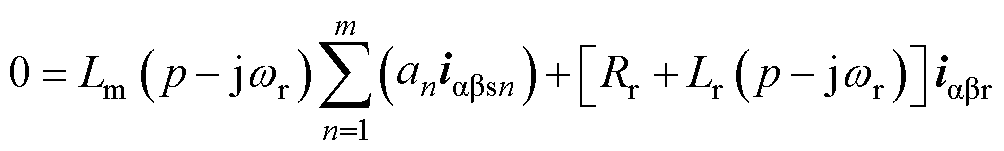 (14)
(14)
其中
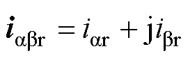
式中,v为动子的速度;t 为极距;uabsn、iabsn、iabr为ab 坐标系第n个定子电压、电流和动子电流。
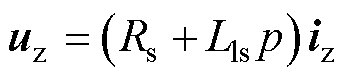
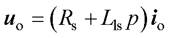
直线感应电机无效机电能量转换部分为
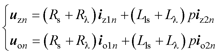 (15)
(15)
其中
式中,uzn、izn为第n个定子段z空间定子电压和电流;uon、ion为第n个定子段o空间定子电压和电流。
直线感应电机第n个定子磁链和动子磁链方程为
 (16)
(16)
其中
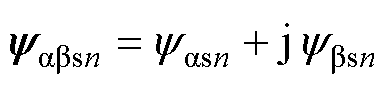
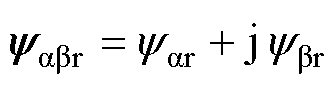
式中,yabsn、yabr为ab 坐标系下第n个定子磁链和动子磁链。动子磁链为本文提出的虚拟动子磁链,当各定子段电流恒定时动子磁链为恒定值。
由式(13)、式(14)和式(16)可得以定子电流和虚拟动子磁链为状态变量的直线感应电机状态方程为
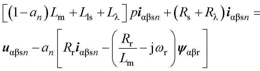 (17)
(17)
 (18)
(18)
该方程为本文提出的直线感应电机解耦建模方法构建的数学模型。
定子分段直线感应电机推进系统通常由数百个定子段和晶闸管切换开关组成,大规模非线性数学模型高效运算方法是实时运算的关键。
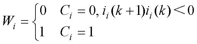
首先,针对晶闸管电流过零关断的特点,采用开关指令与电流过零点判断方法,计算各相晶闸管实际开通或关断状态,有

 (19)
(19)
式中,Ci为各相晶闸管开通关断控制信号;k为离散化数字仿真计算次数。
由LC开关模型实时计算多相直线感应电机各相绕组输入电压如式(20)所示,避免了晶闸管非线性特性的迭代运算,提高了数值运算效率。
 (20)
(20)
其次,针对数百个定子段的大规模电路实时运算难的问题,考虑供电切换过程3台变频器最多同时给6个定子段供电,可将数百个定子段等效为6个定子段循环计算,降低数值运算硬件资源。由6个定子段被动子覆盖比例an实现各定子段数学模型相互解耦并行计算,提高运算效率。采用现场可编程逻辑阵列(Filed Programmable Gate Array, FPGA)硬件加速方式实现系统小步长实时运算[26-27]。
为了验证本文提出的分段供电直线感应电机推进系统非线性特性解耦建模方法的有效性,搭建了硬件在环(Hardware in the Loop, HIL)实验平台如图4所示,包括直线感应电机控制器和数学模型实时仿真器。直线感应电机控制器由Freescale/ PowerPC/P2020双核处理器芯片及Xilinx/A7200T/ FPGA组成,中断时间为100 ms。数学模型实时仿真器由RTLAB5700和RTLAB5607构成,实时计算步长为500 ns。控制器与仿真器之间通信采用Aurora 2.5 Gbit/s,每10 ms交互一次数据。
分段供电直线感应电机推进硬件在环测试系统参数见表1,采用恒定电流和恒定转差间接磁场定向控制策略,电流有效值为7 kA,直线感应电机动子控制分为加速、惰行和制动三个阶段。
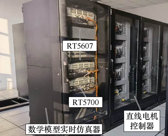
图4 分段直线感应电机推进系统硬件在环实验平台
Fig.4 Hardware-in-the-loop test platform of linear induction motor with segmented stator
表1 硬件在环数学模型参数
Tab.1 The parameters of the HIL model
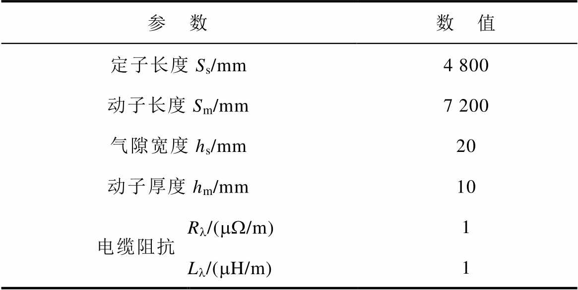
参 数数 值 定子长度Ss/mm4 800 动子长度Sm/mm7 200 气隙宽度hs/mm20 动子厚度hm/mm10 电缆阻抗Rl/(mW/m)1 Ll/(mH/m)1
图5为式(8)所示传统方法硬件在环测试实验结果,图5a和图5b分别为变频器输出电压和电流,图5c为定子段输出推力,图5d为直线电机动子位置和速度。由图5可知,约0.84 s动子位于90 m时,随着电缆长度增加,传统数学模型数值运算发散,与理论分析结果一致。图6~图8为本文提出解耦建模方法硬件在环测试系统实验结果。图6为解耦建模方法硬件在环测试实验结果,当定子电流恒定时,图中虚拟动子磁链在稳态时保持恒定,避免了传统方法动子磁链变化导致实时运算发散的问题。直线感应电机供电电压和推力随定子覆盖比例变化而发生非线性快速时变,计算结果与理论分析一致。图7为解耦建模方法供电切换过程中电压和电流波形细节,在定子供电切换时,变频器输出电流因两定子并联电流产生冲击现象。图7a和图7b为变频器输出电压和电流波形,体现了供电切换过程中变频器输出电流冲击特征。图7c体现了晶闸管各相电流过零关断时电机电流的非线性特性,图7d体现了晶闸管开通过程中电机各相电流特性。图8为解耦建模方法的直线电机推力、位置和速度波形,直线感应电机定子段推力非线性变化特性与理论分析一致,电机最高运行速度达到310 m/s。硬件在环实验结果表明,解耦建模方法快速准确地表征了分段直线感应电机推进系统供电切换和动子进出定子段时电压、电流和推力特性,实时运算步长低至500 ns。

图5 传统方法硬件在环测试实验结果
Fig.5 Hardware in the loop experimental results of the traditional method
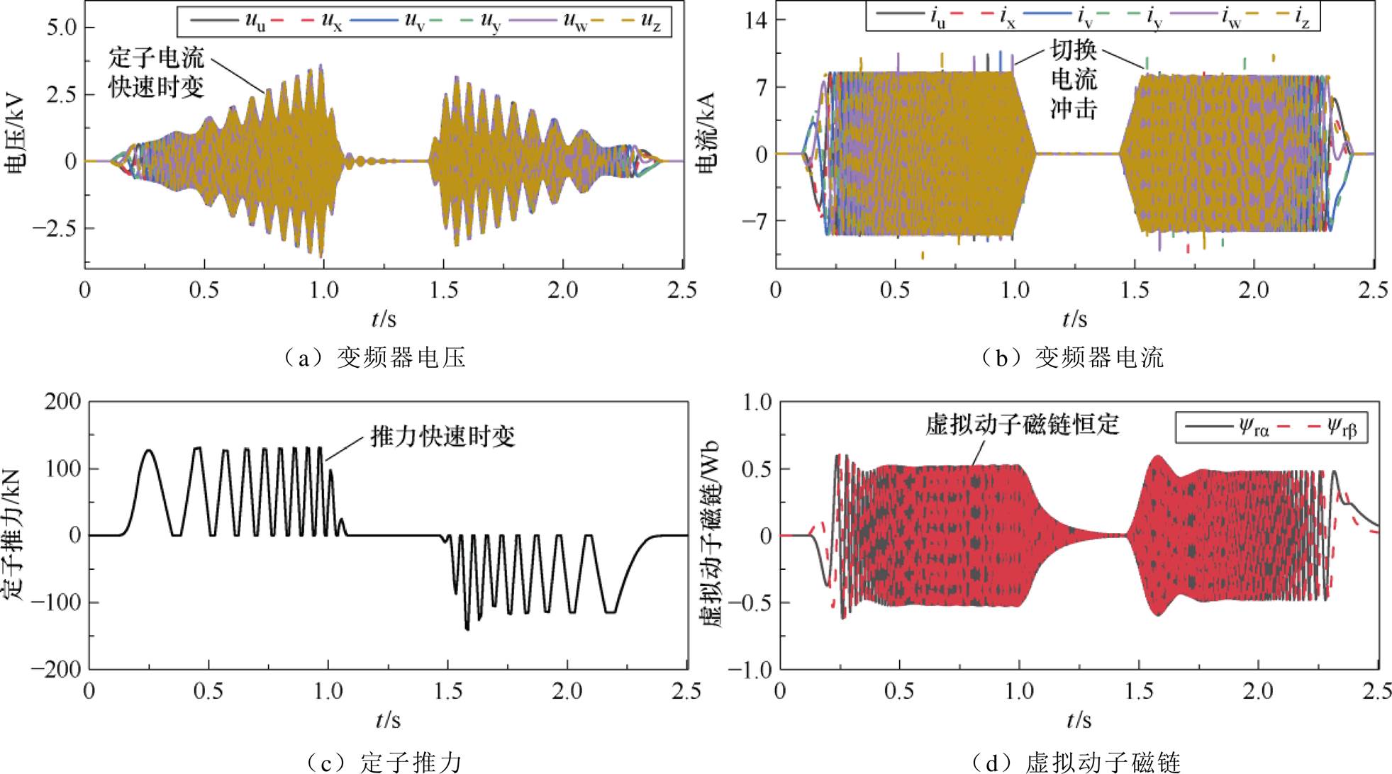
图6 解耦建模方法硬件在环测试实验结果
Fig.6 Hardware in the loop experimental results of decoupled modeling method
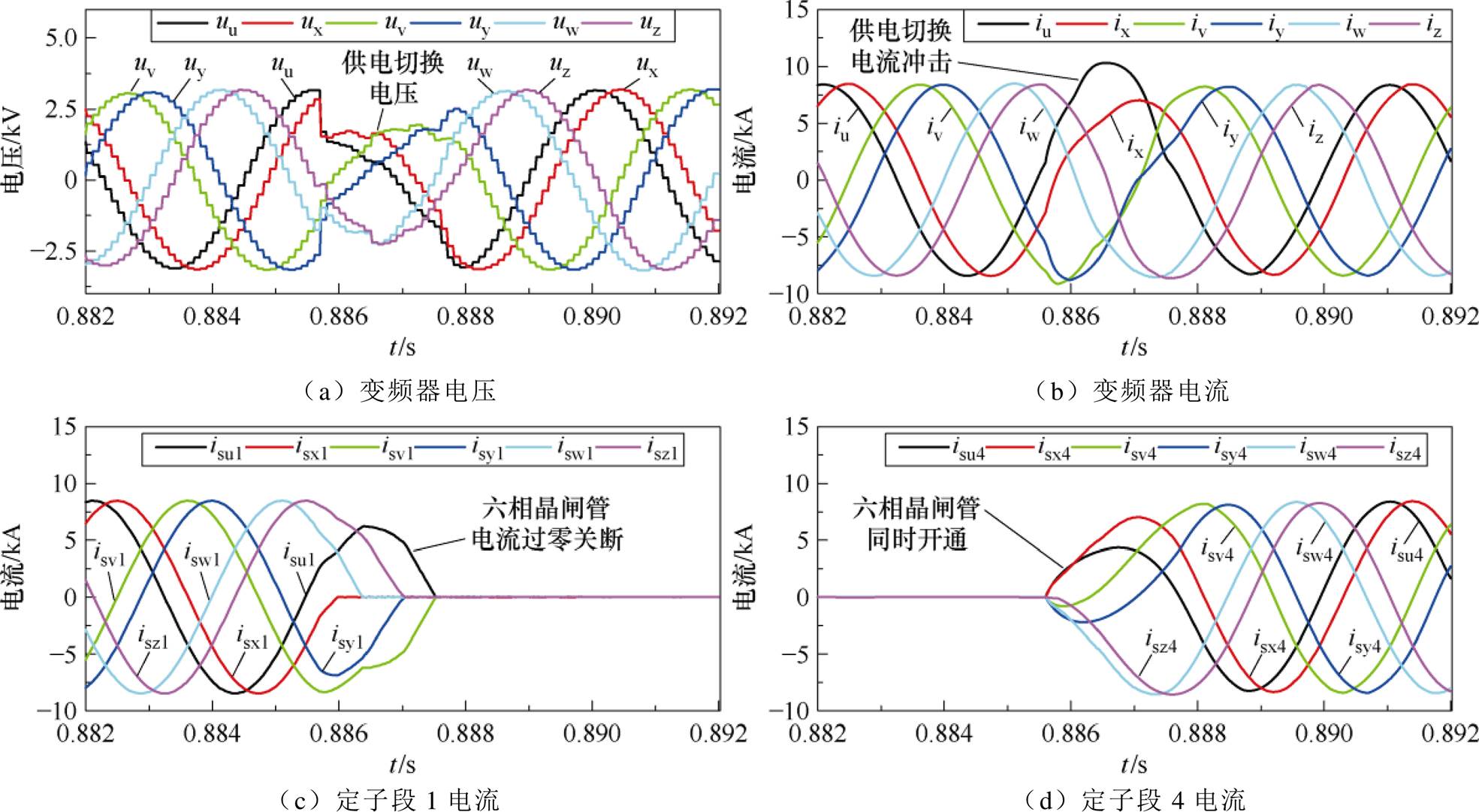
图7 解耦建模方法供电切换过程电机电压和电流波形细节
Fig.7 The detailed voltage and current waveforms of the decoupled modeling method during the switching process
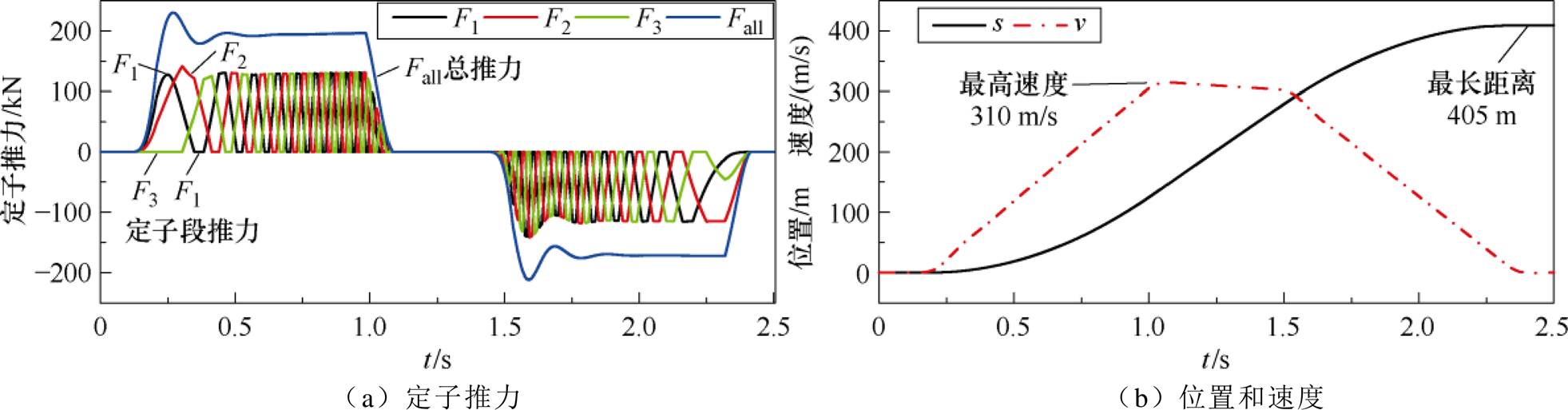
图8 解耦建模方法电机推力、位置和速度波形
Fig.8 The waveforms of the linear induction motor’s thrust, position, and velocity using decoupled modeling method
为了实验验证解耦建模方法的准确性,构建了分段供电直线感应电机推进系统原理样机实验平台如图9所示,包括定子、动子、分段供电设备等。
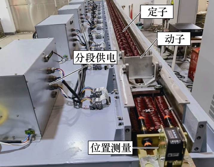
图9 分段供电直线感应电机推进系统实验平台
Fig.9 The experiment platform of linear induction motor with segmented stator
实验平台参数见表2,由24个定子段组成,控制算法与硬件在环测试一致,电流幅值为8 A,频率为20 Hz,供电切换时定子内无动子覆盖。
表2 原样样机实验平台参数
Tab.2 The parameters of the experiment platform
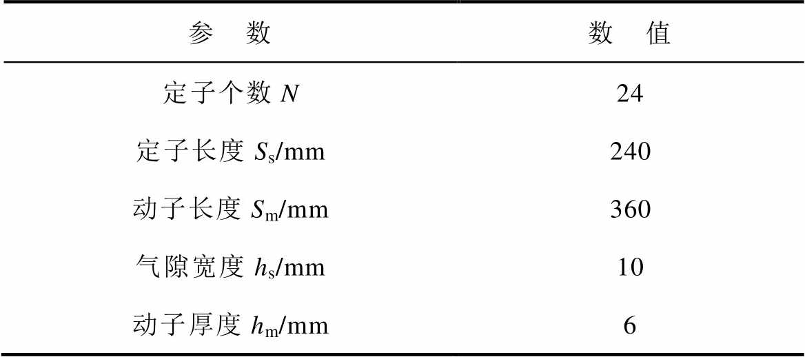
参 数数 值 定子个数N24 定子长度Ss/mm240 动子长度Sm/mm360 气隙宽度hs/mm10 动子厚度hm/mm6
图10为解耦建模方法原理样机实验验证结果,在0.346 s时定子1晶闸管开关关断,定子4晶闸管开关导通。图中,下标f代表硬件在环,e代表实验。图10a为直线感应电机定子1在晶闸管关断过程的电流,图10b为定子4在晶闸管开通过程的电流,图10c为变频器输出总电流,具有供电切换冲击特性。图10中实线为原理样机实验平台实验结果,虚线为硬件在环测试结果。可知,实验结果与硬件在环仿真结果一致性较好,稳态时差别小于7%。原理样机与硬件在环测试实验结果差别主要来源于功率半导体器件开关过程动态特性和直线电机各相电感差异。图10a中晶闸管关断过程定子电流实验结果和硬件在环测试结果有较小差别,主要原因是晶闸管阳极电流小于维持电流晶闸管便提前关断,且在电流过零时IGBT死区也影响变频器电压输出。图10a、图10b和图10c中定子电流y相实验结果和硬件在环测试结果有较小差异,其原因是直线感应电机定子为开断结构,六相绕组之间难以完全对称导致各相电感具有较小差别。由于本文所研究的解耦模型方法和数学模型主要应用于高速直线感应电机推进系统硬件在环测试和高性能控制,该差异对系统级测试及控制影响较小。图10所示实验结果验证了提出的解耦建模方法能够实时准确地表征定子分段多相直线感应电机供电切换过程非线性特性。
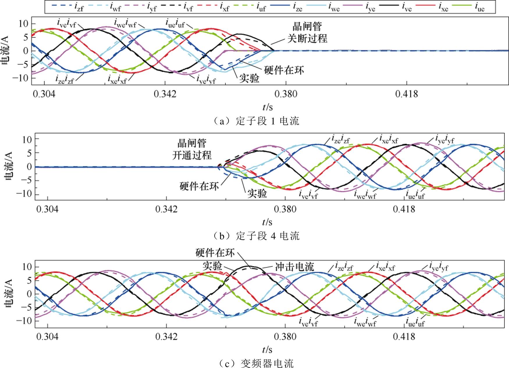
图10 解耦建模方法原理样机实验验证结果
Fig.10 Experimental verification results of decoupled modeling method
本文提出了定子分段直线感应电机推进系统非线性解耦建模方法,得出结论如下:
1)解耦建模方法将直线感应电机推进系统依据能量转换特性划分为有效转换、无效转换和电源三部分,将电缆压降等效为电机内机电能量转换部分,可有效解决传统方法微分项引起的运算发散问题。
2)虚拟动子磁链方法将直线感应电机定子与动子之间的耦合电感视为常数,有效解决覆盖比例系数不可导点引起的电机状态方程运算发散问题。
3)构建的数学模型可实现定子分段直线感应电机推进系统供电切换和定动子耦合变化等多工况的实时准确表征。数学模型硬件在环实时运算步长低至500 ns,与原理样机实验结果误差小于7%。
研究成果可为超高速直线电机推进系统高性能控制提供建模基础。
参考文献
[1] Ma Weiming, Lu Junyong, Liu Yingquan. Research progress of electromagnetic launch technology[J]. IEEE Transactions on Plasma Science, 2019, 47(5): 2197-2205.
[2] 马伟明, 鲁军勇. 电磁发射技术的研究现状与挑战[J]. 电工技术学报, 2023, 38(15): 3943-3959.
Ma Weiming, Lu Junyong. Research progress and challenges of electromagnetic launch technology[J]. Transactions of China Electrotechnical Society, 2023, 38(15): 3943-3959.
[3] 陈萍, 陈垟, 于明月, 等. 基于OPAL-RT的电机模拟器仿真方法[J]. 电气技术, 2023, 24(4): 15-21.
Chen Ping, Chen Yang, Yu Mingyue, et al. Simulation method of motor simulator based on OPAL-RT[J]. Electrical Engineering, 2023, 24(4): 15-21.
[4] Mojlish S, Erdogan N, Levine D, et al. Review of hardware platforms for real-time simulation of elec- tric machines[J]. IEEE Transactions on Transportation Electrification, 2017, 3(1): 130-146.
[5] 杨雄, 张凤阁, 王秀平. 轨道交通用初级永磁型直线电机电磁特性分析[J]. 电气工程学报, 2018, 13(5): 1-7.
Yang Xiong, Zhang Fengge, Wang Xiuping. Elec- tromagnetic characteristics analysis of primary permanent magnet linear motor for rail transit[J]. Journal of Electrical Engineering, 2018, 13(5): 1-7.
[6] 李响, 郭鹏涛, 丁远. 基于场路结合的大功率直线超声波电机压电-热-结构多物理场分析[J]. 电工技术学报, 2024, 39(2): 423-433.
Li Xiang, Guo Pengtao, Ding Yuan. Piezo-thermal- structure coupling analysis for high-power linear ultrasonic motor based on field-circuit combination method[J]. Transactions of China Electrotechnical Society, 2024, 39(2): 423-433.
[7] 周世炯, 李耀华, 史黎明, 等. 分段式双三相永磁直线同步电机的无模型电流预测控制[J]. 电工技术学报, 2024, 39(4): 996-1009, 1021.
Zhou Shijiong, Li Yaohua, Shi Liming, et al. Model- free predictive current control of segmented dual three-phase permanent magnet linear synchronous motor[J]. Transactions of China Electrotechnical Society, 2024, 39(4): 996-1009, 1021.
[8] 韩雪岩, 刘景铭, 朱龙飞. 永磁直线电机端部力抑制措施[J]. 电机与控制学报, 2023, 27(8): 54-63.
Han Xueyan, Liu Jingming, Zhu Longfei. Measures of reducing detent force and design of linear motor[J]. Electric Machines and Control, 2023, 27(8): 54-63.
[9] 聂世雄, 付立军, 许金, 等. 分段供电直线感应电机动子不对称模型及参数计算[J]. 电机与控制学报, 2017, 21(2): 10-17.
Nie Shixiong, Fu Lijun, Xu Jin, et al. Asymmetrical model and parameter calculation of segment-powered linear inductive motor mover[J]. Electric Machines and Control, 2017, 21(2): 10-17.
[10] 许金, 马伟明, 鲁军勇, 等. 分段供电直线感应电机气隙磁场分布和互感不对称分析[J]. 中国电机工程学报, 2011, 31(15): 61-68.
Xu Jin, Ma Weiming, Lu Junyong, et al. Analysis of magnetic field distribution and mutual inductance asymmetry in air gap of linear induction motor with segmented power supply[J]. Proceedings of the CSEE, 2011, 31(15): 61-68.
[11] 鲁军勇, 马伟明, 孙兆龙, 等. 多段初级直线感应电机静态纵向边端效应研究[J]. 中国电机工程学报, 2009, 29(33): 95-101.
Lu Junyong, Ma Weiming, Sun Zhaolong, et al. Research on static longitudinal end effect of linear induction motor with multi-segment primary[J]. Pro- ceedings of the CSEE, 2009, 29(33): 95-101.
[12] 朱俊杰, 吴志程, 许金, 等. 电磁发射直线感应电机多约束改进间接矢量控制策略[J]. 电机与控制学报, 2022, 26(8): 11-20.
Zhu Junjie, Wu Zhicheng, Xu Jin, et al. Improved indirect vector control strategy with multi-constraints of linear induction motor for generalized electro- magnetic launch[J]. Electric Machines and Control, 2022, 26(8): 11-20.
[13] 杨通, 周理兵. 长初级双边直线感应电机纵向动态端部效应 第一部分: 气隙磁场[J]. 电机与控制学报, 2014, 18(4): 52-59.
Yang Tong, Zhou Libing. Longitudinal dynamic end effect in long primary double-sided linear induction motor part 1: airgap magnetic field[J]. Electric Machines and Control, 2014, 18(4): 52-59.
[14] 杨通, 周理兵. 长初级双边直线感应电机纵向动态端部效应 第二部分: 性能计算[J]. 电机与控制学报, 2014, 18(8): 67-74.
Yang Tong, Zhou Libing. Longitudinal dynamic end effect in long primary double-sided linear induction motor part 2: performance calculation[J]. Electric Machines and Control, 2014, 18(8): 67-74.
[15] 鲁军勇, 马伟明, 许金. 高速长定子直线感应电动机的建模与仿真[J]. 中国电机工程学报, 2008, 28(27): 89-94.
Lu Junyong, Ma Weiming, Xu Jin. Modeling and simulation of high speed long primary double-sided linear induction motor[J]. Proceedings of the CSEE, 2008, 28(27): 89-94.
[16] Sun Xiao, Shi Liming, Zhang Zhihua, et al. Thrust control of a double-sided linear induction motor with segmented power supply[J]. IEEE Transactions on Industrial Electronics, 2019, 66(6): 4891-4900.
[17] Guo Keyu, Li Yaohua, Shi Liming, et al. A phase- domain model of dual three-phase segmented powered linear PMSM for hardware-assisted real-time simu- lation[J]. IEEE Transactions on Industry Applications, 2022, 58(4): 4511-4521.
[18] Zhang Mingyuan, Shi Liming. Modeling and cooperative control of segmented long primary double- sided linear induction motor[J]. IEEE Transactions on Industrial Electronics, 2023, 70(2): 1706- 1716.
[19] 徐飞, 李子欣, 孔甘霖, 等. 变长分段直线感应电机数学建模[J]. 中国电机工程学报, 2024, 44(13): 5338-5348.
Xu Fei, Li Zixin, Kong Ganlin, et al. Mathematical model of variable-length segmented linear induction motor[J]. Proceedings of the CSEE, 2024, 44(13): 5338-5348.
[20] 张明元, 马伟明, 徐兴华, 等. 一种考虑电流过零的直线电机分段供电策略[J]. 海军工程大学学报, 2019, 31(4): 11-16.
Zhang Mingyuan, Ma Weiming, Xu Xinghua, et al. A block feeding strategy for linear motor considering switching at current-crossing point[J]. Journal of Naval University of Engineering, 2019, 31(4): 11-16.
[21] 鲁军勇, 马伟明, 李郎如, 等. 高速长初级直线感应电动机纵向边端效应研究[J]. 中国电机工程学报, 2008, 28(30): 73-78.
Lu Junyong, Ma Weiming, Li Langru, et al. Research on longitudinal end effect of high speed long primary double-sided linear induction motor [J]. Proceedings of the CSEE, 2008, 28(30), 73-78.
[22] Wang Ke, Li Yaohua, Ge Qiongxuan, et al. An improved indirect field-oriented control scheme for linear induction motor traction drives[J]. IEEE Transactions on Industrial Electronics, 2018, 65(12): 9928-9937.
[23] 李子润, 徐晋, 汪可友, 等. 电力电子换流器离散小步合成实时仿真模型[J]. 电工技术学报, 2022, 37(20): 5267-5277.
Li Zirun, Xu Jin, Wang Keyou, et al. A discrete small-step synthesis real-time simulation model for power converters[J]. Transactions of China Electro- technical Society, 2022, 37(20): 5267-5277.
[24] 郭希铮, 袁佳琦, 游小杰, 等. 电力电子实时仿真建模的FPGA资源优化方法研究[J]. 电机与控制学报, 2020, 24(7): 12-19.
Guo Xizheng, Yuan Jiaqi, You Xiaojie, et al. Research on FPGA optimization approach of power electronics real-time simulation modeling[J]. Electric Machines and Control, 2020, 24(7): 12-19.
[25] 王钦盛, 王灿, 潘学伟, 等. 基于FPGA的电力电子恒导纳开关模型修正算法及实时仿真架构[J]. 电力系统自动化, 2024, 48(1): 150-159.
Wang Qinsheng, Wang Can, Pan Xuewei, et al. Fixed-admittance switch model correction algorithm and real-time simulation architecture of power electro- nics based on field programmable gate array[J]. Auto- mation of Electric Power Systems, 2024, 48(1): 150-159.
[26] 周斌, 汪光森, 李卫超, 等. 基于FPGA的电力电子系统电磁暂态实时仿真通用解算器[J]. 电工技术学报, 2023, 38(14): 3862-3874.
Zhou Bin, Wang Guangsen, Li Weichao, et al. An FPGA-based general solver for electromagnetic transient real-time simulation of power electronic systems[J]. Transactions of China Electrotechnical Society, 2023, 38(14): 3862-3874.
[27] 何绍民, 张喆, 卢倚平, 等. 基于计算前沿面的实时仿真数值积分并行构造及其数值模型解耦加速方法[J]. 电工技术学报, 2023, 38(16): 4246-4262.
He Shaomin, Zhang Zhe, Lu Yiping, et al. Numerical model decoupling acceleration method with numerical integration parallelism construction based on com- putation front in real-time simulation[J]. Transactions of China Electrotechnical Society, 2023, 38(16): 4246-4262.
Abstract The linear induction motor with a segmented stator (LIM-SS) has great potential for ultra- high-speed electromagnetic propulsion. However, simulating the system’s electromagnetic transient feature in real time poses challenges due to rapid time-varying coupling characteristics between the stator and rotor, zero-crossing thyristor switching current, and varying cable impedance. Mathematical modeling methods for high-speed linear motors mainly include the field-circuit joint operation mathematical model and lumped parameter equivalent circuit mathematical model. While the field-circuit joint operation mathematical model can accurately simulate the system's electromagnetic transient characteristics, it requires extensive computational time and cannot operate in real-time. The lumped parameter equivalent circuit mathematical model is more efficient but struggles to accurately represent the nonlinear characteristics of linear motors. Therefore, this paper proposes a decoupling modeling method for the nonlinear characteristics of the LIM-SS propulsion system.
Firstly, this paper analyzes the electromagnetic transient characteristics of the LIM-SS propulsion system under the conditions of the thyristor switching process, rotor entering, and leaving the stator segment. According to the multi-phase motor space vector decoupling modeling method, the system energy conversion characteristics are divided into three parts: effective conversion, invalid conversion, and power supply. The cable voltage drop is moved into the motor leakage inductance part as the stator invalid electromechanical energy conversion part, which effectively avoids the problem of computational divergence caused by the differential term of inductance when calculating the thyristor voltage. Secondly, this paper proposes a virtual rotor flux modeling method for the virtual invalid electromechanical energy conversion part of the linear motor rotor. From the perspective of the rotor, the mutual inductance between the stator and the rotor of the linear induction motor is a constant, which effectively avoids the problem of state equation computational divergence when the coverage ratio is at a continuous non-differentiable point. Finally, a decoupling mathematical model of the LIM-SS propulsion system is proposed based on the multi-phase motor stator space-vector decoupling modeling and virtual rotor flux method. The thyristor’s switching state is judged by the switch command and the current zero crossing point. The stator coverage ratio realizes the mutual decoupling operation of the mathematical model of each stator segment, and the FPGA hardware acceleration realizes the system's small-step real-time calculation.
The results of the hardware-in-the-loop test indicate that the traditional mathematical model's numerical calculation diverges as the cable length increases. However, the decoupling modeling method can maintain a constant virtual rotor flux in a steady state, thus avoiding real-time calculation divergence. The simulation results align with the theoretical analysis, achieving a real-time calculation step as low as 500 ns. The steady-state variation between the prototype experimental results and the hardware-in-the-loop simulation results is less than 7%. This difference primarily stems from the dynamic characteristics of the power semiconductor device switching process and the disparity in inductance of each phase from a disconnected structure of linear motor stator.
The following conclusions are drawn. (1) The decoupling modeling method equates the cable voltage drop to the electromechanical energy conversion part in the motor. (2) The virtual rotor flux method regards the coupling inductance between the stator and the mover of the linear induction motor as a constant. (3) The constructed mathematical model can realize real-time and accurate characterization of multiple working conditions, such as power supply switching and stator-rotor coupling changes of the stator segmented linear induction motor propulsion system. The results provide a modeling basis for high-performance control of ultra-high-speed linear motor propulsion systems.
keywords:Segmented power supply, multi-phase linear induction motor, thyristor switch, nonlinear characteristics, real-time modeling
中国科学院稳定支持基础研究领域青年团队计划资助项目(YSBR-045)。
收稿日期 2024-06-04
改稿日期 2024-07-08
DOI: 10.19595/j.cnki.1000-6753.tces.240944
中图分类号:TM346
徐 飞 男,1983年生,副研究员,硕士生导师,研究方向为高速直线电机数学建模与优化控制。E-mail: xufei@mail.iee.ac.cn
史黎明 男,1964年生,研究员,博士生导师,研究方向为直线电机和驱动控制、磁悬浮技术、电能无线传输技术等。E-mail: limings@mail.iee.ac.cn(通信作者)
(编辑 崔文静)