图1 旋转导向应用CWPT系统结构示意图
Fig.1 The structure of the CWPT system in rotary steerable system
摘要 针对旋转导向设备使用电场耦合式无线电能传输(CWPT)技术为电池负载供电的应用场景,该文提出一种恒流/恒压自切换的CWPT系统。该系统无需任何额外的主动控制即可实现自动、平滑地从恒流输出到恒压输出的切换,同时系统在两种输出模式下均工作于零相角(ZPA)状态。该文首先给出恒流/恒压自切换CWPT系统的拓扑结构,建立耦合结构等效模型,并对耦合结构模型和物理参数进行设计;然后详细分析系统恒流/恒压的输出特性和工作原理;最后搭建实验样机,验证所提方法与系统结构的有效性,实验中实现了1.5 A的恒流输出和60 V的恒压输出,最高效率为90%。
关键词:电场耦合式无线电能传输 旋转耦合 恒流/恒压 自切换
无线电能传输(Wireless Power Transfer, WPT)技术综合应用了电路理论、电力电子技术、现代控制理论与技术等内容,以磁场[1-2]、电场[3-4]、微波[5]、激光[6]等作为能量载体实现电能的无线传输。其中,电场耦合式无线电能传输(Capacitive Wireless Power Transfer, CWPT)系统以其耦合结构成本低、电磁干扰小、能跨越金属传能、涡流损耗低等优势受到国内外学者的广泛关注,在电动汽车充电、植入式医疗设备、消费电子、水下设备等领域均开展相关研究,并取得了一定的成果[7-10]。
在WPT技术实际应用中,大多采用电池作为负载,而电池充电过程中通常包括恒流充电和恒压充电两个阶段,开始先以恒流模式充电,充电电压随电池等效负载的增大而快速上升,当电压上升到额定值后,切换至恒压模式直至充电结束[11-12]。此外,为提高系统效率、减少无功功率,充电系统在两种模式下均应实现零相角(Zero Phase Angle, ZPA) 运行。
当前实现CWPT系统恒定输出的方法主要有增加控制电路和设计补偿网络两种。文献[13-14]分别设计了不同的外部控制电路实现了CWPT系统输出电压恒定,然而额外的控制电路增加了系统的复杂度和成本。相较之下,通过不同结构补偿网络实现系统恒定输出的方式无需额外的电路与通信,拥有更显著的优势。文献[15]提出双边LC补偿的CWPT系统,可以实现恒流和恒压两种输出模式,但是在恒压输出模式下无法实现ZPA运行。近年来,学者们提出了双边LCLC[16]、CLL-L[17]等多种高阶补偿的恒定输出CWPT系统,推动了CWPT技术的发展和应用,但这些补偿网络结构和参数设计方法只能实现单一类型的恒定输出和ZPA运行。文献[18-19]分别提出了F-F/T和LC-CLCL变结构补偿网络结构,利用二次侧补偿网络内的开关控制CWPT系统在恒流和恒压输出模式间切换。文献[20]则基于LCLC-LC补偿网络的CWPT系统,通过合理地设计工作频率和元件参数,实现了频率切换控制输出模式。以上输出模式切换方法都依赖精准的负载电压检测和控制,频率切换的方法还依赖一次侧和二次侧之间的通信,系统可靠性较差。
此外,当前对CWPT系统的研究中,电场耦合结构大多采用平板式四极板结构,针对旋转工况应用的耦合结构和两组以上极板的解耦设计研究较少。文献[21]设计了一系列套筒式耦合结构,并分析讨论了不同的耦合结构传输性能差异。文献[22]针对多功率传输通道的CWPT系统设计了同侧解耦型平板式电场耦合结构,实现了两组耦合结构的相互解耦。文献[23]基于二次侧解耦极板提出了一种间接测量拾取端感应电压、评估拾取端回路失谐程度的CWPT系统。
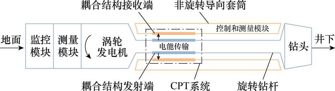
本文针对旋转导向系统中为导向控制和测量模块的电池充电的应用场景展开研究,旋转导向应用CWPT系统结构示意图如图1所示[24]。旋转导向设备由钻头、旋转钻杆、非旋转导向套筒等组成,电场耦合结构发射端安装于旋转钻杆上,接收端安装在非旋转套筒上,电能通过CWPT系统传输至非旋转导向套筒一侧,为套筒上的控制和测量模块的电池充电。
图1 旋转导向应用CWPT系统结构示意图
Fig.1 The structure of the CWPT system in rotary steerable system
基于上述应用场景,本文主要提出了一种恒流/恒压自切换的CWPT系统,该系统随着电池等效负载的升高从恒流输出模式自动过渡至恒压输出模式,无需任何额外的控制方法,具有高鲁棒性。首先,给出恒流/恒压自切换CWPT系统拓扑结构,构建了单发射双接收电场耦合结构的电路等效模型,并结合应用场景进行了耦合结构物理参数设计。其次,对所提系统的恒定输出特性和模式切换过程进行了理论分析。最后,搭建了实验样机,对所提CWPT系统的输出特性进行了实验验证。
本文提出的恒流/恒压自切换CWPT系统拓扑结构如图2所示。Edc为直流电压源,为4个MOSFET(Q1~Q4)组成的全桥逆变器供电,L1、Cx1构成一次侧补偿网络,电场耦合结构包括两块发射极板P1、P2和四块接收极板P3~P6,Ls1、Cx2和Ls2、Lf、Cx3、Cf分别构成两组二次侧补偿网络,两个整流器(VD1~VD4、VD5~VD8)的输出端并联后经过滤波电容Co为电池负载RL充电,Io和Vo分别为电池负载RL上的电流和电压。
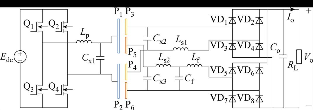
图2 恒流/恒压自切换CWPT系统
Fig.2 Constant current and constant voltage self-switching CWPT system
电场耦合结构采用单发射双接收耦合结构,在接收端设置两组接收极板,二次侧形成了两条能量传输通道,分别采用不同的谐振补偿网络,在整流器输出并联且彼此钳位的作用下,实现了系统输出模式的自切换。
图3为单发射双接收电场耦合结构全耦合电容模型。P1~P6中每两块极板之间均存在耦合电容,因此整个电场耦合结构中共存在15个耦合电容。通常情况下,C12、C34、C56都很小,需要添加外部并联电容Cx1、Cx2、Cx3以降低补偿电感。
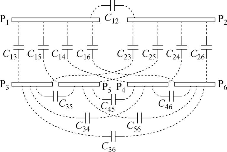
图3 单发射双接收结构全耦合电容模型
Fig.3 Single-transmitter and dual-receiver full-capacitive coupling model
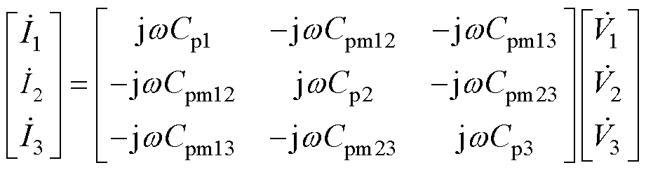
单发射双接收耦合结构受控电流源等效模型如图4所示[25], 、
、 、
、 分别为三个端口所对应的受控电流源输出电流,各个端口输入电压
 、
、 、
、 与输入电流
与输入电流 、
、 、
、 之间满足
之间满足
 (1)
(1)
式中,Cp1、Cp2、Cp3为三个端口的等效自电容,等效自电容已将外部并联电容Cx1、Cx2、Cx3考虑在内,Cpmik(i, k=1, 2, 3,i<k 为受控电流源模型第i端口和第k端口之间的等效互电容,各等效电容分别为
 (2)
(2)
图4 单发射双接收结构受控电流源等效模型
Fig.4 Controlled current source equivalent model of single-transmitter and dual-receiver structure
在受控电流源模型中,等效自电容与受控电流源并联,难以直接得到系统谐振条件和补偿电感值。为解决这一问题,本文提出了单发射双接收电场耦合结构的受控电压源等效模型,如图5所示。
在受控电压源模型中, 、
、 、
、 分别为三个端口所对应的受控电压源输出电压,各端口输入电压和输入电流满足
 (3)
(3)
图5 单发射双接收结构受控电压源等效模型
Fig.5 Controlled voltage source equivalent model of single-transmitter and dual-receiver structure
式中, 、
、 、
、 为受控电压源模型的等效自电容;CMik(i, k=1, 2, 3,i<k为受控电压源模型第i端口和第k端口之间的等效互电容,根据式(1)和式(3),可以得到两种等效模型参数之间的关系如下
 (4)
(4)
其中
 (5)
(5)
在受控电压源模型中,等效自电容、、与受控源串联,能够更为简便地得到电路谐振时补偿电感需要满足的条件。
由1.2节分析可知,单发射双接收电场耦合结构中各端口之间相互耦合,受控电压源模型中、分别与电流、 相关,而本文提出的恒流/恒压自切换CWPT系统需要二次侧输出相互独立,因此需要设计耦合结构实现二次侧互相解耦。
根据文献[22]分析可知,在耦合结构受控电压源模型中,端口间的耦合强度由互容抗XMik衡量,XMik越大代表两端口的耦合程度越高,端口间的互容抗表示为
 (6)
(6)
因此在耦合结构设计过程中,确保XM23=0可实现耦合结构二次侧解耦。本文设计了如图6所示电场耦合结构,其中二次侧同端口极板交错分布,P3~P6四块极板的相对位置关系固定, 为P3~P6每扇弧形极板的圆心角。
图6 二次侧解耦电场耦合结构
Fig.6 Structure of the secondary side decoupled coupler
由文献[26]可知,电场耦合结构传输功率取决于系统工作频率,等效互电容Cpm12、Cpm13、Cpm23和耦合结构端口电压、、,相同的传输功率下,更大的互容抗能够降低耦合结构端口电压,保证系统安全运行,而极板长度l1与等效互电容呈正相关,因此选择l1时尽可能地大。由于系统运行过程中极板之间存在高电压,相邻极板P1和P2、P3和P6、P4和P5之间留出安全距离l2[27]。同时根据相关研究内容[24,28-29],保证耦合结构总长度、内外径尺寸和极板间距处于合理范围,最终确定电场耦合结构尺寸:l1=150 mm,l2=10 mm,r1=70 mm,r2= 80 mm,d=10 mm。
设定3个外部并联电容Cx1=Cx2=Cx3=275 pF,CWPT系统运行频率为1 Hz。以为变量,基于前文的建模方法和Ansys Maxwell有限元仿真得出的全耦合电容矩阵,计算得到如图7所示圆心角与端口互容抗XMik的关系曲线,最终选择=155°使得XM23 XM12且XM23XM13,即XM23可忽略不计。
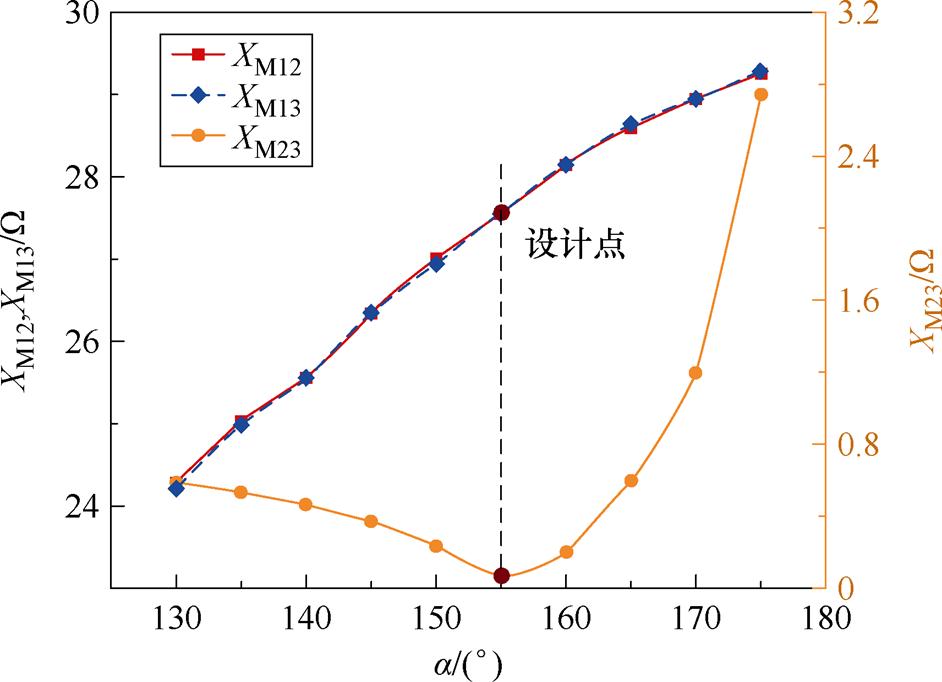
图7 极板圆心角a与端口互容抗XMik关系曲线
Fig.7 Relationship curves between the plate central angle and the port mutual capacitance impedance
根据1.2节中的分析,将图2电路中的电场耦合结构替换为受控电压源模型,并简化得到系统等效电路如图8所示。
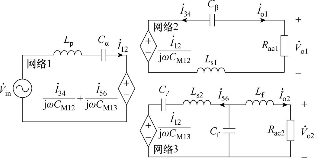
图8 基于受控电压源模型的CWPT系统等效电路
Fig.8 Equivalent circuit of CWPT system based on the controlled voltage source model
外部并联电容Cx1、Cx2、Cx3作为耦合结构的一部分进行了等效,Rac1和Rac2分别为两个整流器的输入交流电阻,因此负载RL可表示为
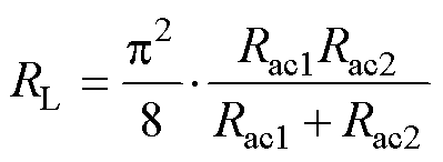 (7)
(7)
系统补偿网络元件参数满足
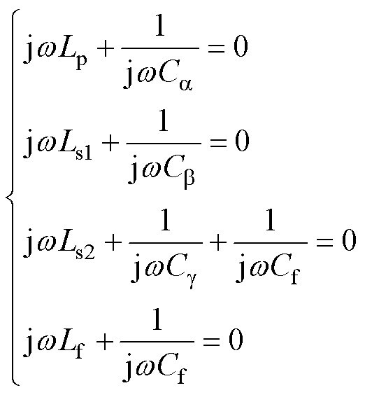 (8)
(8)
由于两个整流器输出并联,输出电压Vo将由 和
和 中更高的值决定。根据系统等效电路和式(8)可计算出
 和
和 为
为
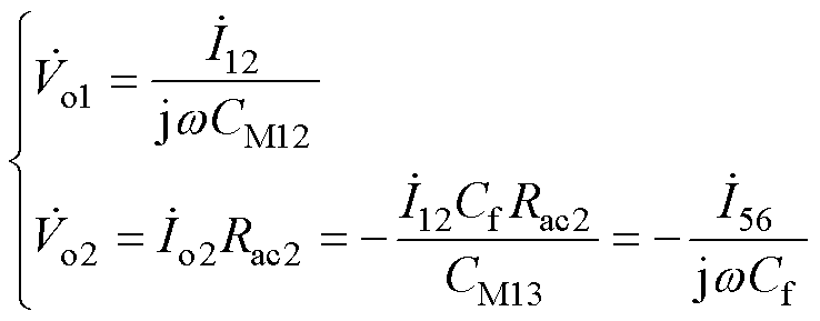 (9)
(9)
定义=时Rac2的值为RC,由式(9)可得RC满足
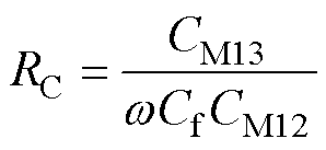 (10)
(10)
在充电开始时,负载RL很小,因此Rac2不足以使 >
> ,输出电压Vo由决定,在此过程中Rac2始终等于RC,因此网络3输出电流
 为
为
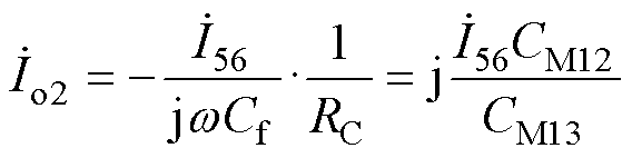 (11)
(11)
此外,在网络1中满足
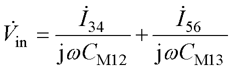 (12)
(12)
根据式(11)和式(12)可得系统直流输出电流Io为
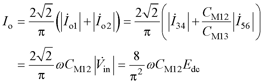 (13)
(13)
因此在负载RL较小的情况下,系统可实现恒流输出,此外,逆变器输入阻抗Zin如式(14)所示,Zin为纯阻性,说明在恒流输出状态下可实现ZPA运行,系统功率因数高。
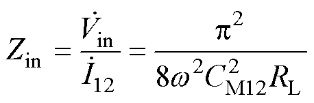 (14)
(14)
电池充电过程中,负载RL逐渐增大,在恒流输出模式下,Rac2保持恒定,Rac1逐渐增加。当RL= (p2/8)RC时,Rac1趋于无穷,系统恒流输出模式终止,进入过渡过程。进入过渡过程后,Rac2不再保持恒定,而是跟随RL增加,输出电压Vo由 决定,即
决定,即
 (15)
(15)
整流器1(VD1~VD4)导通角减小直至关断,而整流器2(VD5~VD8)导通角逐渐增大至完全导通,输出从恒流模式过渡至恒压模式。当RL刚刚超过(p2/8)RC时, 的峰值Vo1peak>Vo仍成立,整流器1(VD1~VD4)是部分导通的,网络2没有被完全阻塞。在Vo1peak<Vo后,整流器1(VD1~VD4)完全关断,网络2是完全阻塞的,进入恒压输出模式[30]。因此进入恒压输出模式临界时刻满足Vo1peak=Vo,即
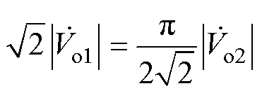 (16)
(16)
结合式(9)和式(10)可得,系统终止恒流输出模式的负载临界值RLC和完成过渡过程进入恒压输出模式的负载临界值RLV分别为
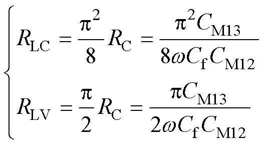 (17)
(17)
当RL>RLV时,系统进入恒压输出模式,由于网络2被阻塞,此时系统是作为传统的S-LCL结构CWPT系统运行的,根据系统谐振关系可得
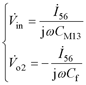 (18)
(18)
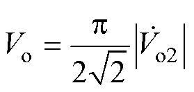
因此系统直流输出电压Vo为
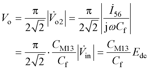 (19)
(19)
由式(19)可知在负载RL>RLV后,可以实现恒压输出。在此模式下,负载RL≡(p2/8)Rac2,逆变器的输入阻抗为
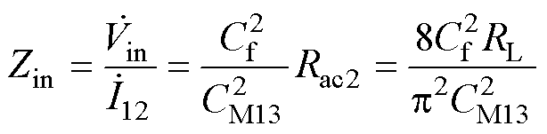 (20)
(20)
恒压输出模式下输入阻抗也为纯阻性,两种输出模式下都能实现ZPA运行,系统功率因数高。基于以上分析,本文提出的CWPT系统共有三个阶段:恒流输出阶段、过渡阶段和恒压输出阶段,所提CWPT系统输出特性曲线如图9所示。充电过程中,随负载RL增加系统自动从恒流输出模式切换至过渡模式再切换至恒压输出模式。
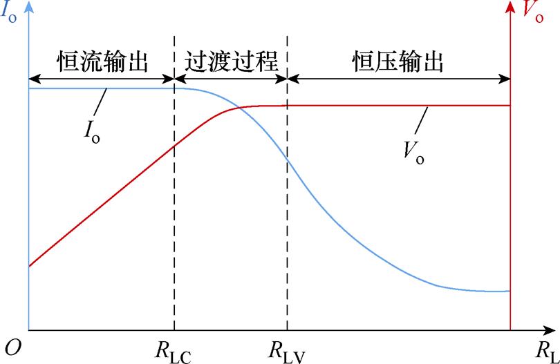
图9 所提CWPT系统输出特性曲线
Fig.9 Output characteristic curves of the proposed CWPT system
根据1.3节中对耦合结构的设计与分析,搭建二次侧解耦的电场耦合结构模型,使用有限元分析法得到板间电容,并根据式(2)和式(4)得到受控电压源等效模型中的等效电容,见表1。
表1 二次侧解耦耦合结构电容参数
Tab.1 Capacitor parameters of the secondary side decoupled coupler
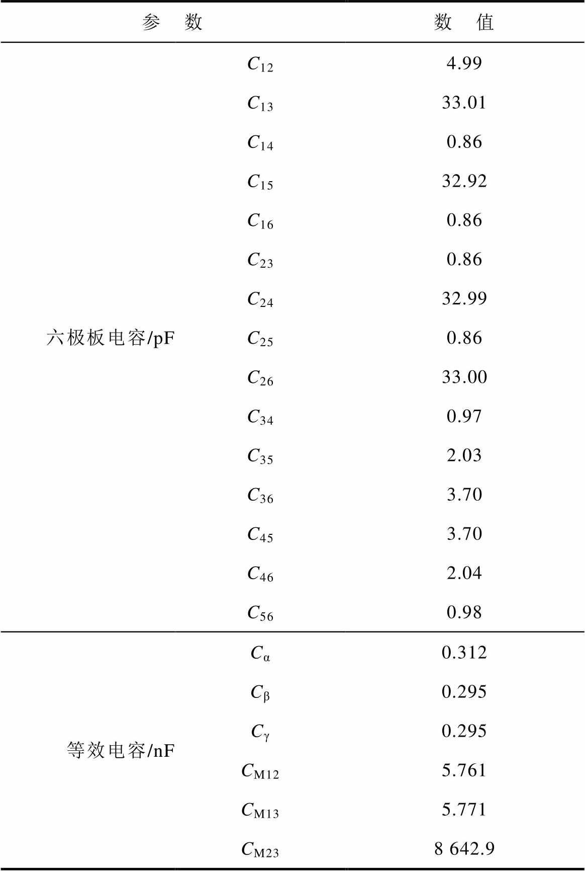
参 数数 值 六极板电容/pFC124.99 C1333.01 C140.86 C1532.92 C160.86 C230.86 C2432.99 C250.86 C2633.00 C340.97 C352.03 C363.70 C453.70 C462.04 C560.98 等效电容/nFCα0.312 Cβ0.295 Cγ0.295 CM125.761 CM135.771 CM238 642.9
系统其余参数见表2。为降低开关损耗,逆变器的MOSFET应工作在零电压软开关(Zero Voltage Switching, ZVS)状态。为实现ZVS,输入阻抗应该是微感性,交流输入电流 滞后于交流输入电压
 ,同时输出增益保持相对稳定。本文提出的系统本身工作过程中始终保持ZPA状态,因此一种实现ZVS的简单方法是在保持其余元件谐振的同时略微增加一次侧补偿电感Lp的大小[15]。
表2 CWPT系统元件参数
Tab.2 CWPT system component parameters
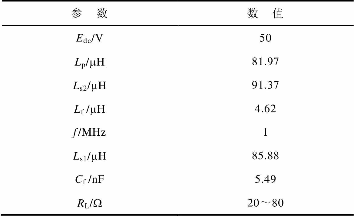
参 数数 值 Edc/V50 Lp/mH81.97 Ls2/mH91.37 Lf/mH4.62 f/MHz1 Ls1/mH85.88 Cf/nF5.49 RL/W20~80
由表2中各元件参数和式(17)计算得出系统终止恒流输出模式的负载临界值RLC≈36 W,进入恒压输出模式负载临界值RLV≈46 W。图10和图11给出了恒流和恒压模式下归一化输出和相应的输入阻抗角随补偿电感Lp和负载RL的变化情况。
从图10和图11中可以看出,略微增大一次侧补偿电感Lp可以使输入阻抗Zin电感化,同时对输出增益的影响相对较小。本次实验中的一次侧补偿电感Lp约为理论值的1.01倍,对应输出电流电压和输入阻抗角与负载的关系在图10和图11中使用红色曲线表示。
将表1和表2中各元件参数代入系统电路中,仿真得到各个极板的电压,进一步通过有限元仿真得到电场耦合结构电场强度分布如图12所示。国际安全标准中要求漏电场小于614 V/m[31],而非旋转套筒中控制和测量模块位于图12标注的高辐射区域以外,因此CWPT系统工作过程中不会对相关仪器设备造成影响。

图10 恒流输出模式下输出电流和输入阻抗角随补偿电感和负载变化情况
Fig.10 Variation of output current and input impedance angle with Lp and RL in constant current output mode
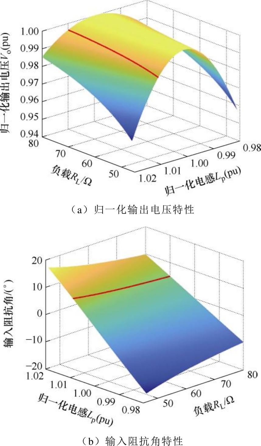
图11 恒压输出模式下输出电压和输入阻抗角随补偿电感和负载变化情况
Fig.11 Variation of output current and input impedance angle with Lp and RL in constant voltage output mode
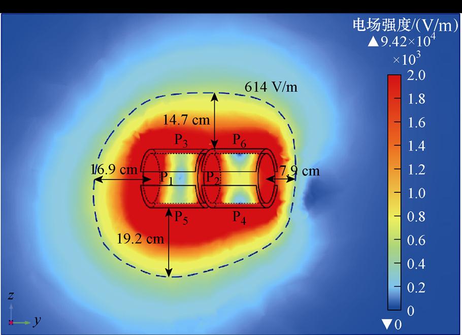
图12 耦合结构漏电场YZ切面
Fig.12 YZ section of coupler leakage field
为验证所提系统结构的可行性和有效性,本文按照图2的电路结构搭建了一套CWPT系统,如图13所示。逆变器Q1~Q4采用大功率高速开关SiC MOSFET IMZ120R045M1,电容器采用高耐压薄膜电容以满足补偿电容高电压应力要求,电感使用利兹线绕制的空心电感,减少电能传输过程中的损耗,实验过程中使用电子负载模拟不同充电阶段电池的不同阻值进行可变负载实验。
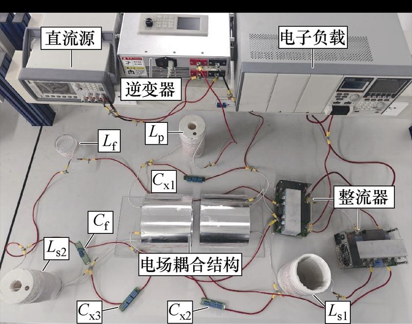
图13 自切换CWPT系统实验装置
Fig.13 Experimental prototype of a self-switching CWPT system
图14给出了RL=30、40、60 W时,对应恒流输出、过渡过程和恒压输出三种模式下逆变器输出电压、逆变器输出电流和负载电压Vo对应的实验波形,其中,略微滞后于,保证了系统在不同工作模式下实现ZVS。
图15为系统充电过程中实测的输出电压Vo、输出电流Io与电池组等效负载RL的关系曲线。在恒流输出阶段,Io的值基本不变;恒流输出向恒压输出转变的过程中,Io值有所下降,Vo值逐渐升高;在恒压输出阶段,Vo值有小幅上升。恒流模式下充电电流Io波动变化小于5%,恒压模式下充电电压Vo变化小于3%。

图14 不同模式下 、
、 和Vo的实验波形
Fig.14 Experimental waveforms of , ,Vo in different modes
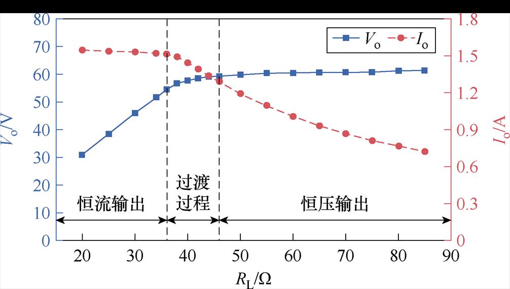
图15 充电电压和充电电流随负载变化曲线
Fig.15 Variation curves of charging voltage and charging current with load
图16为系统实测功率与效率曲线。系统运行过程中,输出功率随负载RL增大先增加后减小,整体效率保持在83%以上。当RL≈42 W时,系统峰值功率约为86 W,效率约为90%。进入恒压输出模式后,系统功率和效率随RL增大而变小,当系统功率为45 W时,效率下降到85.5%。
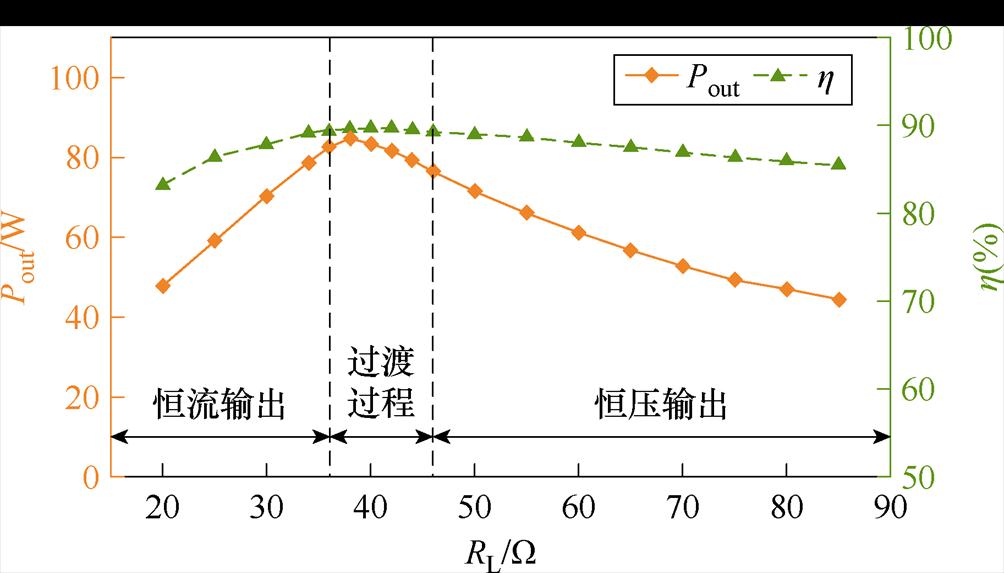
图16 系统功率与效率随负载变化曲线
Fig.16 Variation curves of power and efficiency with load
为了验证旋转工况下系统输出特性,分别对恒流输出模式(RL=30 W)和恒压输出模式下(RL= 60 W)的充电电流Io、充电电压Vo和传输效率h 与耦合结构一次侧和二次侧相对旋转角度的关系进行实验,实验结果如图17所示。
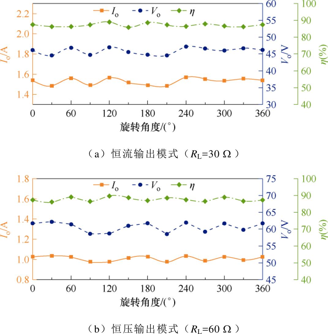
图17 不同模式下充电电流、充电电压和传输效率随耦合结构旋转角度的变化
Fig.17 Variation of charging current, charging voltage and efficiency with coupler rotational angle in different modes
恒流输出模式(RL=30 W)下最大输出电流为1.57 A,最小输出电流为1.49 A,输出波动约为5.1%,传输效率在87.5%左右波动;恒压输出模式(RL=60 W)下最大输出电压为62.1 V,最小输出电压为58.5 V,输出波动约为5.8%,传输效率在88%左右波动。旋转过程中,耦合结构的耦合电容C12~C56理论上不会发生变化,出现波动的原因主要是手动固定耦合结构产生的相对位置误差,导致系统耦合电容容值出现波动。
本文提出了一种应用于旋转导向设备中电池充电场景的CWPT系统,该系统采用单输入双输出的电路结构,无需额外的控制方法和相应电路即可自动实现输出模式切换,简化了控制方案,提高了系统的可靠性。针对该系统,本文首先提出了单发射双接收电场耦合结构的受控电压源等效模型,大大简化了耦合结构补偿分析。其次针对单发射双接收的电场耦合结构,设计了一种旋转工况应用的二次侧解耦的耦合结构模型,通过物理参数设计的方法消除了两组接收极板间的互耦合。然后本文应用所提出的耦合结构等效模型对该系统输出特性进行了理论分析。最后搭建了实验装置进行验证,系统传输功率为86 W时,最大效率达到90%,且系统能够随负载值的增加从恒流输出模式自动过渡至恒压输出模式。
参考文献
[1] 贾亚辉, 王智慧, 肖静, 等. 磁耦合无线电能传输系统宽范围零电压开关实现方法[J]. 电工技术学报, 2024, 39(22): 6952-6964.
Jia Yahui, Wang Zhihui, Xiao Jing, et al. Imple- mentation method of wide range zero voltage switching in magnetic coupling wireless power transfer system[J]. Transactions of China Elec- trotechnical Society, 2024, 39(22): 6952-6964.
[2] 吉莉, 葛富辰, 张弛, 等. 基于电磁耦合结构的谐振屏蔽及抗偏移性能研究[J]. 电工电能新技术, 2023, 42(7): 68-76.
Ji Li, Ge Fuchen, Zhang Chi, et al. Research on resonance shielding and anti-misalignment per- formance based on electromagnetic coupling structure[J]. Advanced Technology of Electrical Engineering and Energy, 2023, 42(7): 68-76.
[3] 刘耀, 肖晋宇, 赵小令, 等. 无线电能传输技术发展与应用综述[J]. 电工电能新技术, 2023, 42(2): 48-67.
Liu Yao, Xiao Jinyu, Zhao Xiaoling, et al. Development and application review on wireless power transmission technology[J]. Advanced Tech- nology of Electrical Engineering and Energy, 2023, 42(2): 48-67.
[4] 张鑫, 杨帅鑫, 王文杰, 等. 电场耦合无人机无线电能传输系统轻量化抗偏无线输电耦合机构研究[J]. 电工技术学报, 2025, 40(14): 4343-4354.
Zhang Xin, Yang Shuaixin, Wang Wenjie, et al. Study on Lightweight Anti-Bias Wireless Transmission Coupling Mechanism for Electric Field Coupled UAV WPT System[J]. Transactions of China Electrote- chnical Society, 2025, 40(14): 4343-4354.
[5] 荣灿灿, 严俐慧, 路聪慧, 等. 基于超材料与超表面的无线电能传输技术研究现状与进展综述[J]. 电工技术学报, 2023, 38(20): 5369-5384.
Rong Cancan, Yan Lihui, Lu Conghui, et al. Over- view on research status and progress of wireless power transfer technology based on metamaterials and metasurfaces[J]. Transactions of China Electro- technical Society, 2023, 38(20): 5369-5384.
[6] 王得安, 张剑韬, 朱春波, 等. 海洋环境对水下无线电能传输系统的影响机理研究进展[J]. 电工技术学报, 2025, 40(3): 653-675.
Wang Dean, Zhang Jiantao, Zhu Chunbo, et al. Review of progress in the study of marine environment effects on underwater wireless power transfer systems[J]. Transactions of China Elec- trotechnical Society, 2025, 40(3): 653-675.
[7] 唐丁源, 周玮, 黄亮, 等. 具有恒压输出特性的电场耦合式动态无线电能传输技术[J]. 电工技术学报, 2023, 38(20): 5385-5397.
Tang Dingyuan, Zhou Wei, Huang Liang, et al. Dynamic electric-filed coupled wireless power transfer system with constant voltage output characteristics[J]. Transactions of China Electro- technical Society, 2023, 38(20): 5385-5397.
[8] Yang Lei, Feng Baoxiang, Zhang Yuanqi, et al. Single wire capacitive wireless power transfer system for wearable biomedical sensors based on flexible graphene film material[J]. IEEE Transactions on Biomedical Circuits and Systems, 2022, 16(6): 1337- 1347.
[9] Chang Yufang, Zhang Xiaoke, Ma Chao, et al. A constant voltage/current CPT system with lightweight characteristics for the unmanned aerial vehicle[J]. IEEE Access, 2023, 12: 1737-1746.
[10] 苏玉刚, 檀竹斌, 胡宏晟, 等. 电场耦合电动车动态无线充电系统及耦合机构设计方法[J]. 中国电机工程学报, 2025, 45(4): 1599-1610.
Su Yugang, Tan Zhubin, Hu Hongsheng, et al. Electric-field coupled dynamic wireless charging system for electric vehicles and the design method of coupler[J]. Proceedings of the CSEE, 2025, 45(4): 1599-1610.
[11] 杨云虎, 贾维娜, 梁大壮, 等. LCC-LCC/S自切换恒流-恒压复合型无线电能传输系统[J]. 电工技术学报, 2023, 38(18): 4823-4837, 4852.
Yang Yunhu, Jia Weina, Liang Dazhuang, et al. A self-switching wireless power transfer system based on hybrid topology of LCC-LCC/S with constant current and constant voltage[J]. Transactions of China Electrotechnical Society, 2023, 38(18): 4823-4837, 4852.
[12] 李中启, 张晨曦, 王建斌, 等. 基于变频重构S/SP拓扑的无线电能传输系统恒流恒压研究[J]. 电工技术学报, 2024, 39(15): 4718-4732.
Li Zhongqi, Zhang Chenxi, Wang Jianbin, et al. Research on constant current and constant voltage of WPT system based on variable frequency recon- figuration S/SP topology[J]. Transactions of China Electrotechnical Society, 2024, 39(15): 4718-4732.
[13] 苏玉刚, 颜志琼, 胡宏晟, 等. 基于频率切换实现恒流/恒压输出的电场耦合无线电能传输系统[J]. 中国电机工程学报, 2024, 44(4): 1553-1565.
Su Yugang, Yan Zhiqiong, Hu Hongsheng, et al. Electric-field coupled wireless power transfer system with constant current/constant voltage output characteri- stics based on frequency switching[J]. Proceedings of the CSEE, 2024, 44(4): 1553-1565.
[14] Zang Shaoge, Lu Kai, Nguang S K, et al. Robust- output feedback control of a rotary capacitive power transfer system[J]. IEEE Access, 2019, 7: 113452- 113462.
[15] Lu Fei, Zhang Hua, Hofmann H, et al. A double-sided LC-compensation circuit for loosely coupled capa- citive power transfer[J]. IEEE Transactions on Power Electronics, 2018, 33(2): 1633-1643.
[16] 王卓, 牛小方, 杨明, 等. LCLC电场式无线电能传输的耦合分析与实验[J]. 电力电子技术, 2023, 57(11): 63-67.
Wang Zhuo, Niu Xiaofang, Yang Ming, et al. Coupling analysis and experiment of electric field wireless power transfer in bilateral LCLC[J]. Power Electronics, 2023, 57(11): 63-67.
[17] Wang Shiying, Liang Junrui, Fu Minfan. Analysis and design of capacitive power transfer systems based on induced voltage source model[J]. IEEE Transactions on Power Electronics, 2020, 35(10): 10532-10541.
[18] 苏玉刚, 谢诗云, 王智慧, 等. 基于F-F/T变结构谐振网络的恒压-恒流型电场耦合电能传输系统[J]. 电工技术学报, 2019, 34(6): 1127-1136.
Su Yugang, Xie Shiyun, Wang Zhihui, et al. An electric-field coupled power transfer system with constant voltage and constant current output based on F-F/T changeable resonant circuit[J]. Transactions of China Electrotechnical Society, 2019, 34(6): 1127- 1136.
[19] 廖志娟, 周磊, 吴镇, 等. 变结构LC-CLCL拓扑恒压恒流型电场耦合电能传输系统[J]. 中国电机工程学报, 2021, 41(17): 6039-6049.
Liao Zhijuan, Zhou Lei, Wu Zhen, et al. An electric-field coupled power transfer system with constant voltage and constant current output based on changeable LC-CLCL resonant circuit[J]. Proceedings of the CSEE, 2021, 41(17): 6039-6049.
[20] Lian Jing, Qu Xiaohui. An LCLC-LC-compensated capacitive power transferred battery charger with near-unity power factor and configurable charging profile[J]. IEEE Transactions on Industry Appli- cations, 2022, 58(1): 1053-1060.
[21] Wu Xueying, Su Yugang, Hu A P, et al. A sleeve-type capacitive power transfer system with different coupling arrangements for rotary application[J]. IEEE Access, 2020, 8: 69148-69159.
[22] 周玮, 高侨, 陈泽林, 等. 基于同侧解耦型电场耦合机构的多发射多接收无线电能传输系统[J]. 电工技术学报, 2023, 38(18): 4811-4822.
Zhou Wei, Gao Qiao, Chen Zelin, et al. Same-sided decoupled electric-field coupler based wireless power transfer system with multi-transmitter and multi- receiver[J]. Transactions of China Electrotechnical Society, 2023, 38(18): 4811-4822.
[23] 周玮, 郑宇锋, 陈泽林, 等. 基于副边解耦极板的电容式无线电能传输系统拾取端失谐评估[J]. 电力系统自动化, 2024, 48(3): 142-149.
Zhou Wei, Zheng Yufeng, Chen Zelin, et al. Detuning estimation of pickup loop in capacitive wireless power transfer system based on secondary-side decoupled capacitive coupler[J]. Automation of Electric Power System, 2024, 48(3): 142-149.
[24] Ji Li, Ge Fuchen, Zhang Chi. Design of wireless power transmission coupling structure based on rotary steerable drilling[J]. IEEE Transactions on Power Electronics, 2023, DOI: 10.1109.TPEL.3023.3319577.
[25] 胡杰, 陈丽华, 罗博, 等. 基于全耦合电容模型的双发射电场耦合式无线电能传输系统[J]. 电工技术学报, 2019, 34(17): 3542-3551.
Hu Jie, Chen Lihua, Luo Bo, et al. Electric field coupled power transmission system with dual transmitting terminals based on full-capacitive coupling model[J]. Transactions of China Electro- technical Society, 2019, 34(17): 3542-3551.
[26] Wang Yao, Zhang Hua, Lu Fei. Review, analysis, and design of four basic CPT topologies and the application of high-order compensation networks[J]. IEEE Transactions on Power Electronics, 2022, 37(5): 6181-6193.
[27] Liu Yipeng, Wu Tao, Fu Minfan. Interleaved capacitive coupler for wireless power transfer[J]. IEEE Transactions on Power Electronics, 2021, 36(12): 13526-13535.
[28] Jia Jianbo, Jia Yahui, Li Xiaofei. Analysis, design, and experimental verification of a parallel wireless power and data transmission method for rotary steering systems[J]. Energies, 2022, 15(17): 6349.
[29] 张辉, 刘庆波, 底青云, 等. 井下非接触电能传输耦合器仿真与优化[J]. 地球物理学进展, 2022, 37(4): 1780-1788.
Zhang Hui, Liu Qingbo, Di Qingyun, et al. Simulation and optimization of downhole contactless power transmission coupler[J]. Progress in Geophysics, 2022, 37(4): 1780-1788.
[30] Wang Youzheng, Liu Hongchen, Yu Huiying, et al. A hybrid battery wireless charger for self-adapting battery charging curve and anti-misalignment[J]. IEEE Journal of Emerging and Selected Topics in Industrial Electronics, 2023, 4(4): 1192-1203.
[31] 钱林俊, 于博泉, 刘亚兵, 等. 具有抗偏移及漏电场屏蔽特性的UUV电场耦合无线电能传输系 统[J/OL]. 电源学报, 1-13 [2025-02-05]. http://kns. cnki.net/kcms/detail/12.1420.TM.20231219.0952.004.html.
Qian Linjun, Yu Boquan, Liu Yabing, et al. Electric- filed coupled wireless power transfer system for UUV with anti-offset and leakage field shielding characteristics[J/OL]. Journal of Power Supply, 1-13 [2025-02-05]. http://kns.cnki.net/kcms/detail/12.1420. TM.20231219.0952.004.html.
Abstract Brushes and slip rings in rotary steerable systems are the main equipment for power transmission under rotational conditions to charge the batteries in steering control and measurement modules. However, this transmission method is prone to generating electrical sparks, potentially triggering safety risks. In addition, the wear and tear caused by long-term operation may lead to poor contact, resulting in unstable power transmission, which reduces the stability of the power supply in a rotary steerable system. Wireless power transfer (WPT) technology can address the issues of poor power supply safety and stability caused by traditional brushes and slip rings. The capacitive power transfer (CPT) system offers advantages such as low eddy current loss and strong resistance to electromagnetic interference. It is well-suited to withstand harsh conditions in the downhole.
The battery charging process typically includes two stages: constant current charging and constant voltage charging. Firstly, the charging is carried out in constant current mode, where the charging voltage rises rapidly as the equivalent load of the battery increases. Once the voltage reaches the rated value, it switches to constant voltage mode until the charging process is complete. This paper proposes a CPT system that automatically switches between constant current and voltage modes. The system achieves a smooth, automatic transition from constant current output to constant voltage output without additional active control while maintaining zero phase angle (ZPA) operation in both output modes.
The topology of the CPT system with automatic switching between constant current and constant voltage modes was presented. The electric field coupler adopted a single transmitter and dual receiver structure in the system. Therefore, the coupler’s voltage source equivalent model was established. Then, a decoupled secondary-side single-transmitter dual-receiver coupler model was designed based on physical parameter design to avoid mutual interference between the secondary side inputs. The system's output characteristics were theoretically analyzed. The system's output characteristics gradually transition from constant current output to constant voltage output as the load increases. The system maintains the ZPA state throughout the entire charging process.
Electromagnetic simulation of the electric field distribution of the coupler was conducted using the finite element method. The simulation results show that the leakage electric field generated by the coupler during system operation does not interfere with the normal operation of the instruments in the rotary steerable system. Then, a prototype was built. The experimental results indicate that the system can achieve a constant current output of 1.5 A and a constant voltage output of 60 V. The current fluctuation is less than 5% in the constant current output mode, the voltage fluctuation is less than 3% in the constant voltage output mode, and the maximum transmission efficiency is approximately 90% during system operation. These results meet the constant current and constant voltage requirements for battery charging.
Keywords:Capacitive wireless power transfer, rotary coupler, constant current and constant voltage, self- switching
中图分类号:TM724
DOI: 10.19595/j.cnki.1000-6753.tces.242269
国家自然科学基金资助项目(52377020)。
收稿日期 2024-12-17
改稿日期 2025-01-06
吉 莉 女,1981年生,教授,博士生导师,研究方向为无线电能传输技术和能源互联网。
E-mail: huanxir@126.com
张家琦 男,1997年生,硕士研究生,研究方向为电场耦合式无线电能传输技术。
E-mail: 2022216006@student.cup.edu.cn
(编辑 陈 诚)