图1 直驱式PMSG风力发电系统内部结构
Fig.1 Direct-drive PMSG WPGSs
摘要 风力发电系统(WPGS)中的并网逆变器(GCI)在运行过程中常受参数扰动影响,这会导致WPGS并网性能下降。为此,该文考虑GCI的内外参数扰动,基于连续高阶滑模超螺旋(Super-Twisting)算法设计GCI鲁棒控制系统。首先,构建了包含直流电压外环、交流电流内环和交流电压内环的GCI系统模型,同时考虑直流母线瞬时功率波动和GCI内部参数扰动;其次,为减少传统SMC的固定增益与抖振问题,根据GCI电流环与电压环的工作特性,分别构造具有时变增益与可预估增益的积分型Super-Twisting滑模控制器(STSMC),以高效控制GCI与电网侧的交互功率,减少因系统不确定性边界造成的过度控制增益的能量损耗;然后,根据Lyapunov理论证明了该文所提控制策略的稳定性和有限时间收敛性;最后,设计了考虑参数扰动的多工况仿真和实验,结果表明所提控制策略有效地减小了GCI系统受扰后的输出信号波动,提高了其动态响应能力与WPGS的并网电能质量。
关键词:并网逆变器 Super-Twisting算法 风力发电系统 参数扰动 积分型滑模
风力发电作为一种重要的可再生能源技术,其在电力系统中的应用越来越广泛[1]。现代风力发电系统(Wind Power Generation System, WPGS)的主要部件包含直驱式永磁同步发电机(Permanent Magnet Synchronous Generators, PMSG)、机侧整流器(Machine-Side Rectifier, MSR)、并网逆变器(Grid-Connected Inverter, GCI)及主控制[2]。其中,GCI作为核心部件,可同时实现对直流链路的电压反馈与网侧电能的稳定馈入[3]。然而由于风能的强随机性、高爆发性与不稳定性,导致PMSM输出功率易存在波动现象,进而使得GCI在并网过程中易受MSR输出直流电压的扰动,长时间下去还会造成GCI内部参数的快速老化,严重时还可能导致电网功率与负荷不匹配,引发大面积的停电事故[4-5]。
通过设计高效稳定的GCI控制系统来实现WPGS的高效可靠并网,是目前解决上述问题的热点研究方向[6-7]。而实际工程应用型的GCI控制策略仍不断聚焦于PI控制及其扩展上:文献[8]设计了由双向DC-DC变换器与带有LCL滤波器的三电平T型GCI组成的功率转换系统,通过引入PI控制器实现对GCI包含的直流链路电压及dq轴电流的协调控制;文献[9]设计了一种面向储能系统的多源GCI控制系统,其结合PI策略与空间矢量脉宽调制(Space Vector Pulse Width Modulation, SVPWM)技术,通过改变GCI开关脉冲有效减少系统功率损耗;文献[10]进一步结合PI控制与分数阶谐波干扰观测器以抑制GCI直流和交流分量的周期性干扰,增强了其对电网频率的适应性;文献[11]为解决GCI系统应对直流侧电压波动时的复杂控制计算问题,结合PI控制与PWM技术选择最优的GCI开关顺序,以平衡其直流链路的电压波动。
随着GCI应用场景的拓展,不断有学者将H∞控制[12]、模型预测控制[13-14]、神经网络控制[15]、滑模控制(Sliding Mode Control, SMC)[16]等先进控制策略应用于GCI的控制系统中:文献[17]针对非理想电网环境,提出GCI系统的直流外环PI控制与交流内环线性H∞控制结合的二次调节策略,抑制了GCI控制系统的参数漂移;为降低LCL滤波器型GCI系统的输出谐波含量,文献[18]提出了一种简化型模型预测控制方法,提升了GCI系统的快速响应性能;文献[19]在文献[18]的基础上将神经网络控制器应用于GCI的交流内环控制中,增强了对GCI的内环电流控制;文献[20]针对GCI的输出跟踪问题,提出了一种连续输出反馈终端滑模控制(Terminal Sliding Mode Control, TSMC)方法,以保证系统输出在有限时间内收敛。
分析上述GCI控制策略,其突出特点与局限性体现在:
(1)直流侧瞬时功率调节是GCI并网稳定运行的有效方法,且SVPWM是GCI的有效控制方法。
(2)被广泛使用的PI控制虽能够在GCI抗扰方面表现出次优性能,但其控制性能受LCL滤波器谐振与控制频率间狭窄裕度的影响。
(3)针对GCI模型参数不确定性的研究较少,且忽视了对控制器鲁棒性能的研究。
(4)目前应用于GCI的SMC技术依赖于控制律切换项与GCI开关控制信号间的配合,导致抖振问题的存在,进而限制了GCI在高开关频率、大输出功率条件下的广泛应用。
为了解决上述问题,本文基于连续超螺旋滑模控制(Super-Twisting Sliding Mode Control, STSMC),设计GCI的积分型鲁棒SMC策略。首先设计直流电压外环瞬时功率STSMC控制器,有效调节直流链路电压,提升其抗外部输入扰动能力,并为交流内环提供精确的参考信号;其次利用时变增益构造积分型STSMC控制器,以消除交流电流内环的过增益抖振现象,并提升GCI电流环输出精度;最后借助可预估增益条件设计积分型STSMC,用于管理GCI交流电压内环与电网间的交互功率,实现交流内环误差的快速收敛,进而提高GCI系统的整体输出性能与鲁棒性。
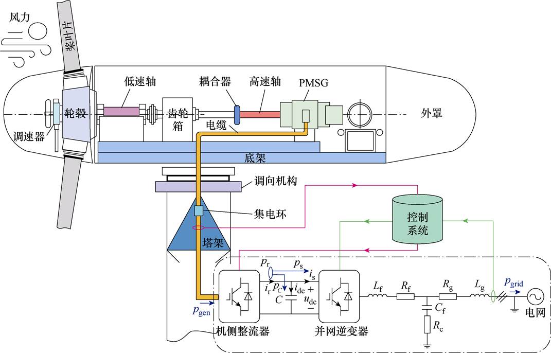
图1给出了WPGS的内部结构,其包含直驱式PMSG、MSR、GCI、电网侧及主控系统五部分[21]。其中,GCI采用LCL型滤波器以降低输出信号谐波;MSR与GCI通过功率电容C连接以减少损耗。风力带动桨叶转动,机械能通过齿轮与PMSG相连,产生初级交流电先通过MSR一次变流,再经逆变器二次变流,后被注入电网,完成电能转换。
图1 直驱式PMSG风力发电系统内部结构
Fig.1 Direct-drive PMSG WPGSs
图1中,pgen为MSR输入侧总功率,pr为其输出侧瞬时功率;ps为GCI的瞬时输入功率;pC为流向连接电容C的功率;udc为直流侧平衡系统功率变化的电压;pgrid为GCI注入网侧总功率,图2给出了详细风力发电系统简化拓扑结构。
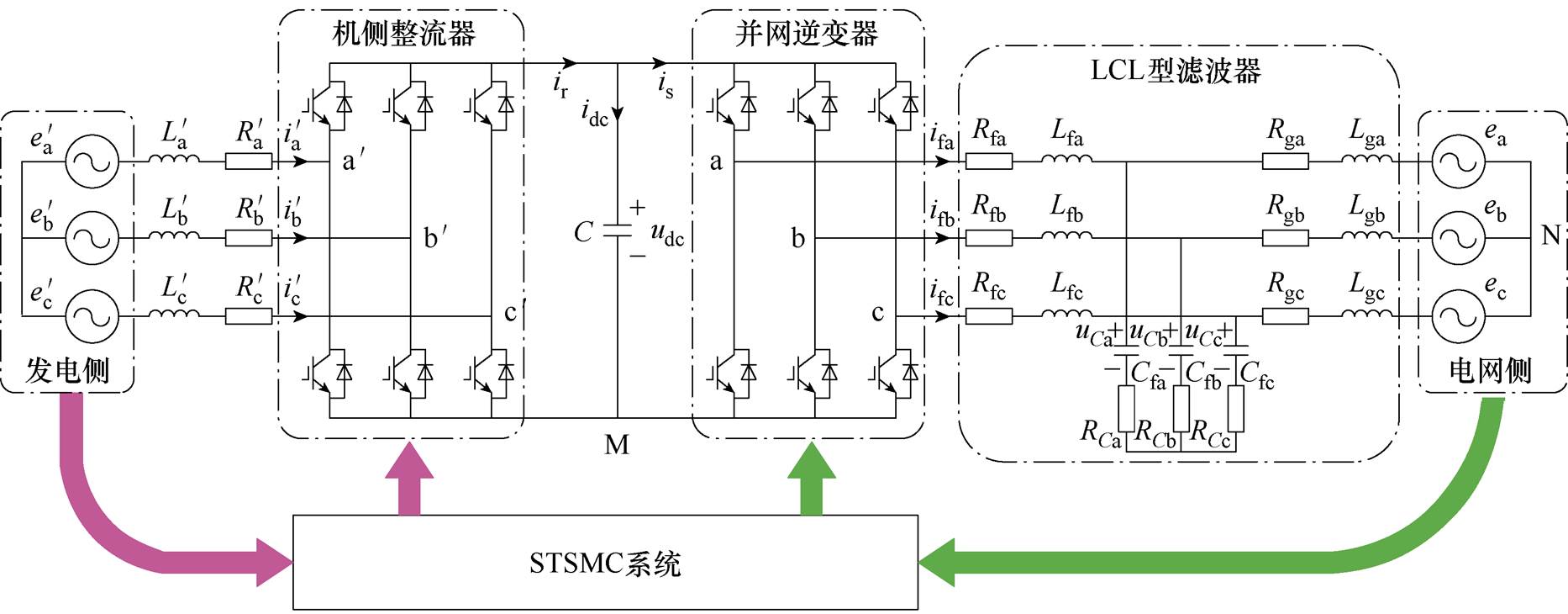
图2 风力发电系统简化拓扑结构
Fig.2 Simplified topology of the WPGS
图2中, 为PMSG产生的三相电压,k=a, b, c;
 和
和 为发电侧传输线路电感与等效电阻;ek为电网侧电压;Lfk和Lgk分别为GCI侧与电网侧滤波电感,Rfk与Rgk为对应的寄生电阻;Cfk为滤波电容,RCk为其串联的寄生电阻以减少共振;ir为MSR输出电流;idc为流经C的电流;is为流入GCI的电流。为了简化对GCI系统分析,这里假设以下两个理想因素:①忽略电网侧电压谐波影响;②忽略各变换器的开关损耗。
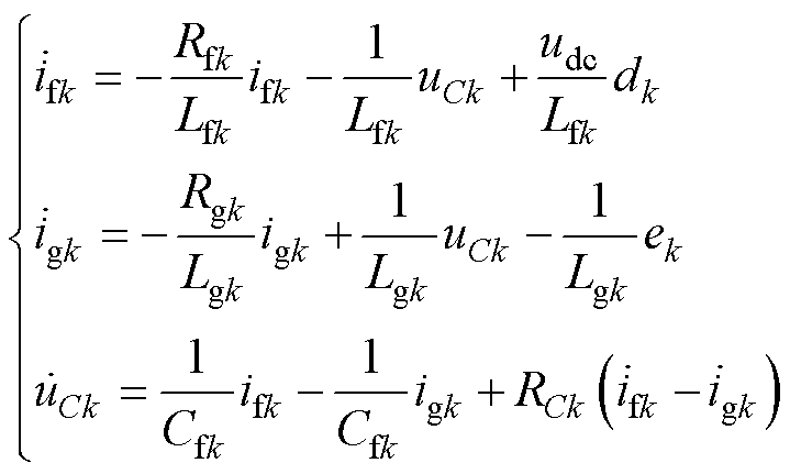
图2中,基于Kirchhoff电流定律,可得到abc静态坐标系下的GCI输出电流模型为
 (1)
(1)
式中,ifk和igk分别为流经滤波电感Lfk和Lgk的三相电流, ;uCk为滤波电容Cfk两端电压;dk为功率管的开关调制信号,通常配合SVPWM模块给出。
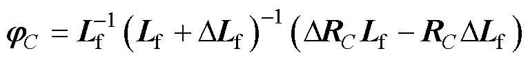
在实际应用中,由于器件制造时无法保证一致的额定值,且外界环境因素不确定,使得式(1)中的参数扰动情况必须被考虑。GCI扰动参数主要包括:①内部电感器Lfk与Lgk,电网侧波动可对其产生直接影响,且环境温度变化、设备老化也会导致电感值下降[22];②内部电容器Cfk,设备老化会造成其电荷存储能力减弱,进而导致电容值降低[23];③内部寄生电阻Rfk、RCk及Rgk,材料老化与高温工况会导致其实际阻值变大[24];④外部直流侧输入电压参考值 ,其因外部干扰因素会出现幅值波动[25]。
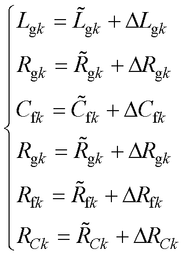
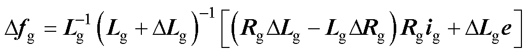
由此,模型式(1)中被考虑的参数扰动包括Lgk、Rgk、Cfk、RCk、Lfk、Rfk,且可被进一步描述为
 (2)
(2)
式中, 、
、 、
、 、
、 、
、 、
、 分别为对应电感器、电阻器、电容器的标称值;DLfk、DRfk、DLgk、DRgk、DCfk、DRCk为参数值的变化量。
为了方便图2中对GCI控制系统的设计,可将式(1)中的系统电流模型转换为矩阵形式,有
 (3)
(3)
 (4)
(4)
 (5)
(5)
 (6)
(6)
 (7)
(7)
其中
uC=[uCa uCb uCc]T if=[ifa ifb ifc]T
ig=[iga igb igc]T e=[ea eb ec]T d=[da db dc]T
Rg=diag( ,
,  ,
,  ) RC=diag(
 ,
,  ,
,  )
)
Rf=diag( , , ) Lg=diag(
 ,
,  ,
,  )
)
Lf=diag( ,
,  ,
,  ) Cf=diag(
 ,
,  ,
,  )
)
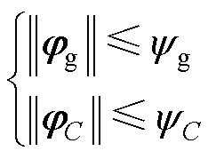
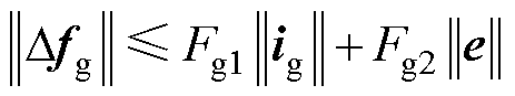
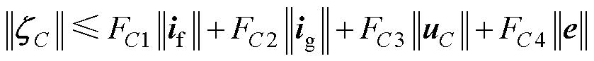
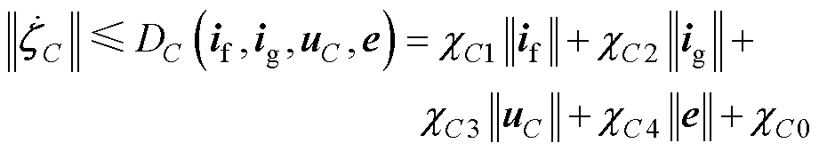
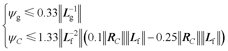
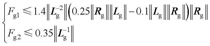
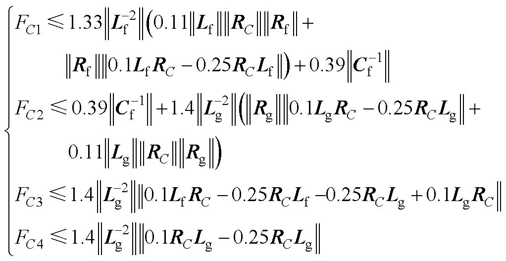
由式(2)中给出的参数变化特性,易知式(4)~式(7)的不确定项均有边界值,即
 (8)
(8)
 (9)
(9)
 (10)
(10)
 (11)
(11)
 (12)
(12)
式中,yg、yC、Fgm(m=1, 2)、FCn(n=1, 2, 3, 4)、cgj(j=0, 1, 2, 3)、cCl(l=0, 1, 2, 3, 4)为不确定项的边界值。
本文所提控制系统基于ab 坐标系建立,其不仅能够清晰表达线路功率传输关系,且不需要考虑锁相环的复杂设计。通过Clarke变换Xab=TXabc或Xabc=PXab(X=if、ig、uC、ug、d)得
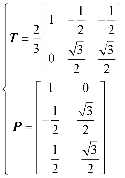 (13)
(13)
可将式(3)中的电流模型进一步转换为
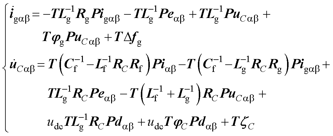 (14)
(14)
式中,igab=[iga igb]T、iab=[ia ib]T、uCab=[uCa uCb]T、dab=[da db]T为ab 坐标系下的系统电流、网侧电流、系统电压及控制信号;eab=[ea eb]T为ab坐标系下的网侧电压。
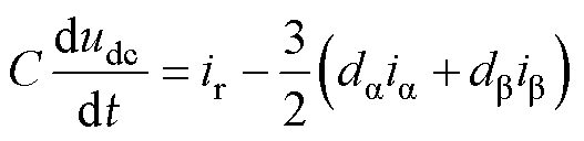
除了式(14)中所示的交流电流动态模型外,图2中的风力发电系统还包含直流侧电压动态模型,依据电容C的储能特性可将其表示为
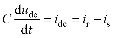 (15)
(15)
图2中,结合Kirchhoff电流定律,可将式(15)中流入GCI的电流is进一步表示为
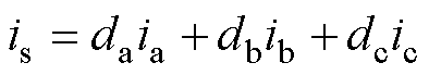 (16)
(16)
基于式(13)中的Clarke变换iab=Tiabc或iabc=Piab,式(16)可被重写为
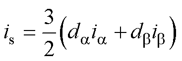 (17)
(17)
其中
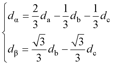 (18)
(18)
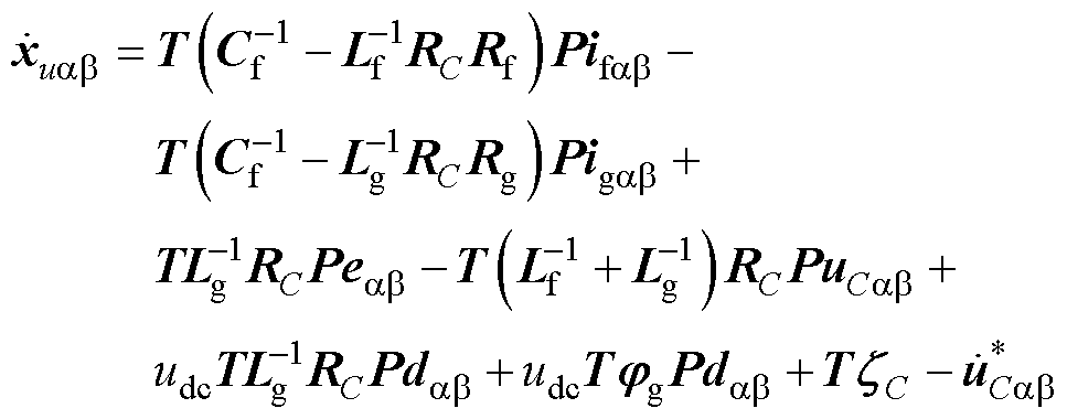
进一步将式(17)代入式(15)可得
 (19)
(19)
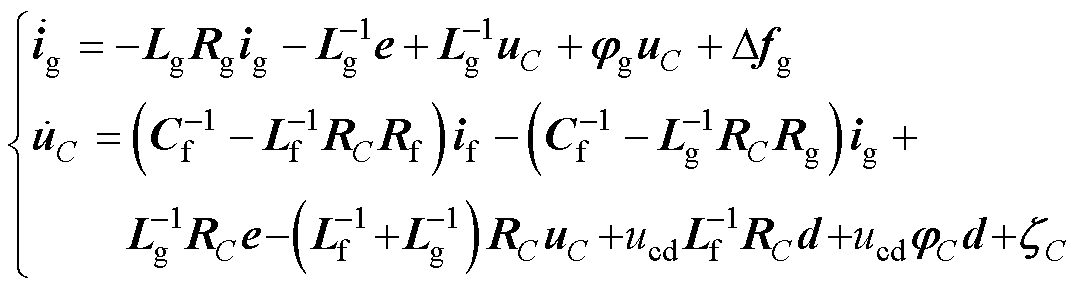
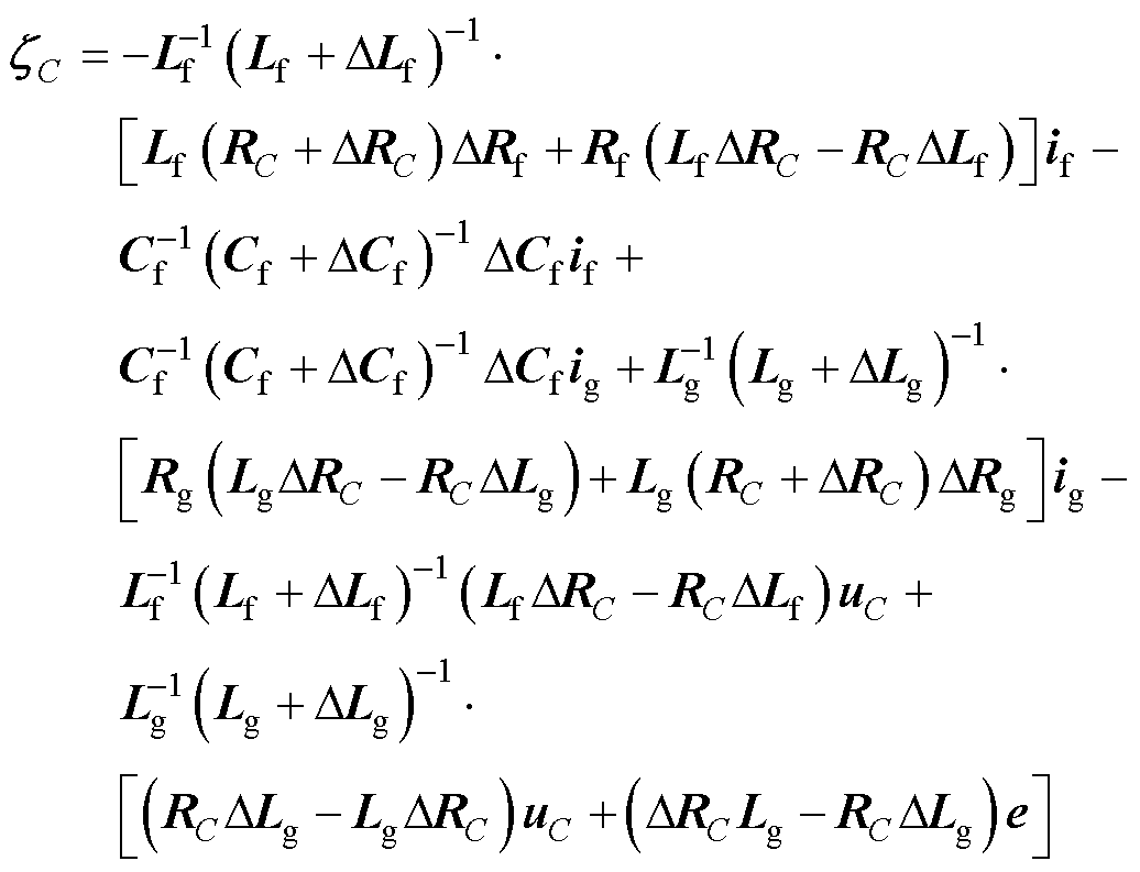
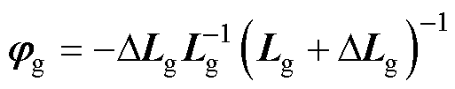
由此得到了ab坐标系下的GCI输出电流模型式(14)与直流侧电压模型式(19)。
式(3)所示的GCI模型中,考虑了 、
、 、
、 和
和 四种参数扰动。可将其分为匹配扰动
 和非匹配扰动
 ,其中、为与实际或虚拟控制项相关的不确定增益。且式(1)中的GCI模型基于理想网侧谐波与系统开关损耗情况的假设,但仍需注意,实际电网中的电压谐波会影响GCI系统的电流控制精度和输出电能质量;且开关损耗会导致GCI转换效率降低,影响整体系统的热管理和动态响应;由于本文研究内容的侧重,故不对上述两点内容做细致研究与讨论。
如图3所示为GCI控制系统框图,其中包括直流电压外环、交流电流内环、交流电压内环三部分。其中电压外环依据直流链路电压参考值给出GCI所需参考功率;交流内环控制器保障GCI的输出性能,帮助减轻不平衡电网中的电感、电容等器件参数变化对系统的影响。因此,所设计STSMC的控制调节对于GCI系统的可靠运行至关重要。
图3中的直流电压外环通过将直流链路电压维持在一恒定值,计算系统瞬时有功与无功功率,给出交流内环所需参考值 和
和 。图4给出了电压外环控制器的内部结构,包含STSMC控制器与低通滤波器1/(1+sTf),其中Tf为时间常数。
在式(15)两边同时乘以udc得
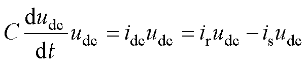 (20)
(20)
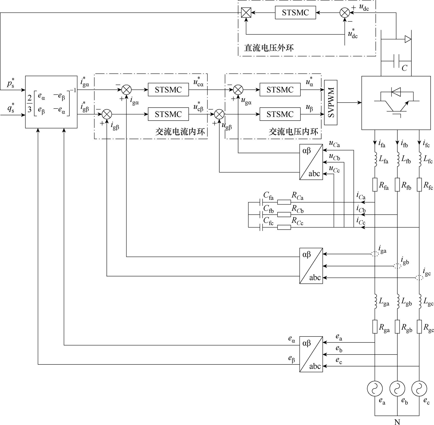
图3 GCI控制系统框图
Fig.3 Diagram of the GCI control system
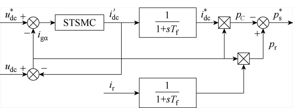
图4 直流电压外环控制结构
Fig.4 Structure of the DC voltage outer loop
从功率传递角度分析,可将式(20)改写为
 (21)
(21)
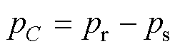
式中,pC=C(dudc/dt)udc、pr=irudc、ps=isudc分别为图1中连接电容侧、整流器输出侧、GCI输入侧的瞬时功率。结合图4可知,当受扰增大时,由于pr在短时间内保持不变,电容C上消耗的功率pC会随一定程度的增大,进而导致ps降低。
在三相三线制PMSG系统中,应用瞬时功率理论[26]可得到GCI输出视在功率S为
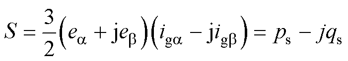 (22)
(22)
式中,ps、qs分别为GCI输出有功与无功功率,且此处ps与式(21)中相同。由式(22)可将GCI输出功率进一步表示为
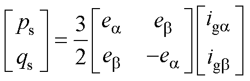 (23)
(23)
定义 、
、 为有功与无功功率参考值,由式(23)可给出ab坐标系下GCI输出电流参考值、为
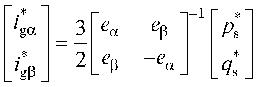 (24)
(24)
为了使系统理想功率因数接近1,即保证发电侧向电网侧电能传输效率的最大化,故这里有必要将式(23)中的无功功率校准为0,即=0。由于功率因数等于有功功率ps与视在功率|S|的比值,则通过GCI的实际输出功率就可估计发电转换效能。
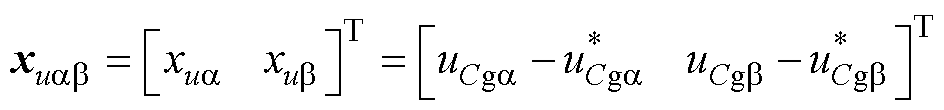
图4中的STSMC控制器内部结构如图5所示,图中, 为STSMC的输出调节电流。
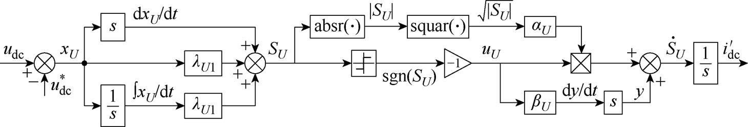
图5 直流电压外环控制的内部结构
Fig.5 Internal structure of the DC voltage outer loop
定义该电压外环输出侧电压差状态变量xU为
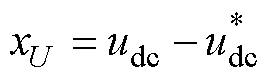 (25)
(25)
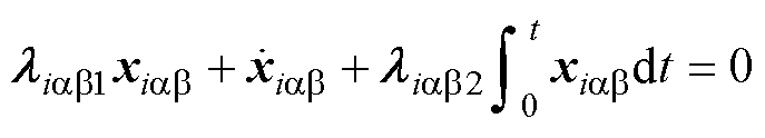
进一步可设计滑模面SU与控制律uU分别为
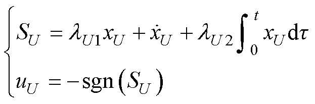 (26)
(26)
式中,lU1>0为比例项参数,用于调节udc的响应速度;lU2>0为积分项参数,用于调节输出稳态误差,帮助提升电压外环输出参考功率的精度。
对式(26)中的滑模面求导可得
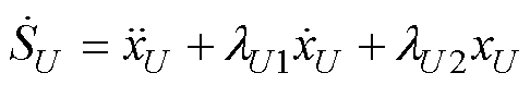 (27)
(27)
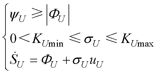
为保证电压状态能够沿预设滑模面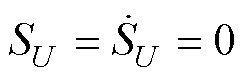 到达原点,利用积分思想可设计SU的导数为
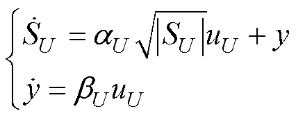 (28)
(28)
式中,( ,
,  )>0为控制律预估增益;含的y项可被视为等效控制律,负责驱使电压状态迅速到达;含项可被视为切换控制律,负责迫使电压状态沿到达原点。由式(28)易知,通过积分运算可实现SU控制律的连续化。
为使所设计的STSMC能够实现有限时间内的快速收敛,增益、的预估范围需满足
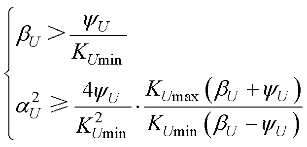 (29)
(29)
其中
 (30)
(30)
式中, 为系统非确定连续可导函数
 的上界;KUmin、KUmax分别为系统非确定连续可导函数
 的下、上界。
图6给出了式(30)约束下积分型STSMC系统收敛相轨迹。可见,系统电压状态在式(27)、式(28)的控制律下以螺旋曲线收敛至零点,且系统相轨迹与 轴的每次相交均伴随着控制律项y(t)符号的改变。换而言之,y(t)项中切换函数sgn( · )符号来回切换迫使系统状态不断向原点收敛,这也是SMC策略强鲁棒性所在[27]。
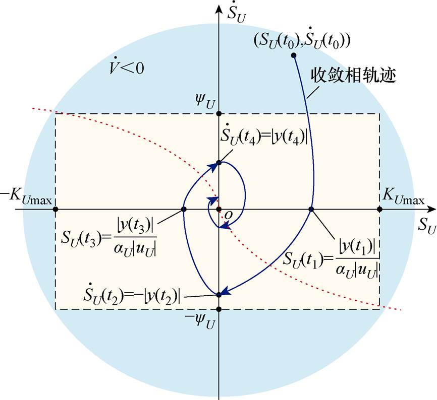
图6 积分型STSMC控制系统相轨迹
Fig.6 Integral type STSMC control system phase trajectory
为了进一步证明所设计STSMC系统能够在有限个周期T内稳定收敛,考虑Lyapunov函数VU为
 (31)
(31)
对式(31)求导,并将式(26)、式(28)代入得
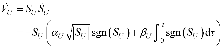
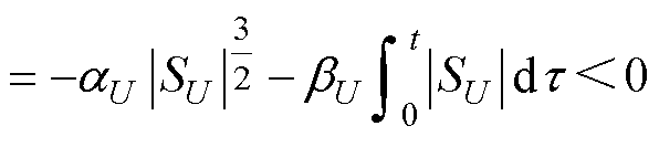 (32)
(32)
由式(32)可知,所设计SMC系统满足滑模存在条件 <0,即母线电压跟随SMC系统可以达到自稳定状态。
相较于传统SMC策略,式(29)、式(30)中设计的可预估增益将系统的收敛状态限制在了如图6所示的蓝色区域中,为实际不同工况下STSMC增益范围的选择提供了计算依据,从而避免了因控制增益的过度设置导致的不必要的能量损耗(波形比较详见附图1)。
交流电流内环控制结构如图7所示。同样定义电流环的输入电流误差为状态变量为
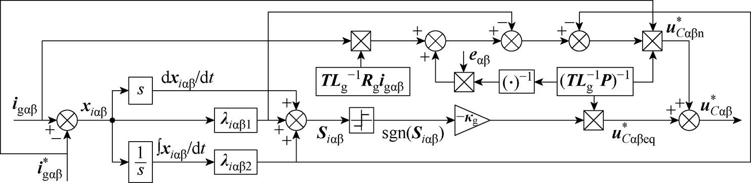
图7 交流电流内环控制结构
Fig.7 Structure of the AC current inner loop
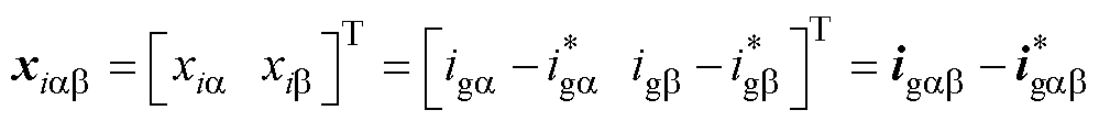 (33)
(33)
式中,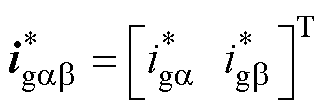 为电流参考值,由式(24)给定。
由式(33)可得到电流误差变化率为

 (34)
(34)
定义电流内环滑模面为
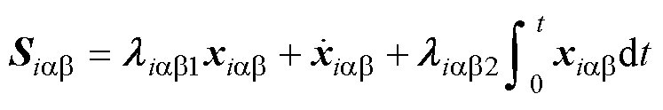 (35)
(35)
式中,滑模面 ;
; =
= ;
; =
= ,且
,且 、
、 、
、 、
、 均为正数。
均为正数。
定理1:在式(36)~式(39)中的虚拟控制律 的约束下,式(33)中的电流状态
 能够实现沿预设滑模面
 运动的有限时间收敛。
 (36)
(36)
 (37)
(37)
 (38)
(38)
 (39)
(39)
式中, 为虚拟等效控制律;
 为积分型虚拟切换控制律;
 为时变增益;
 为调节参数,
 。
。
证明:通过将式(34)中的电流误差变化率代入到式(33)中得到
 (40)
(40)
式中,为式(36)中的虚拟控制律,能够确保电流状态 快速响应并跟随参考值
 。
。
将式(36)代入式(40)后可得
 (41)
(41)
对式(41)求导可得
 (42)
(42)
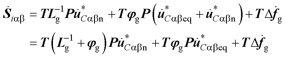
进一步构建Lyapunov方程为
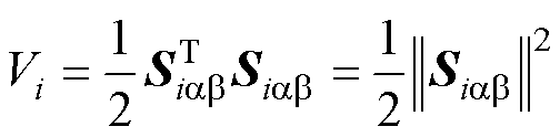 (43)
(43)
对Vi求导并将式(42)代入式(43)中可得
 (44)
(44)
再将式(9)代入式(44)中得到
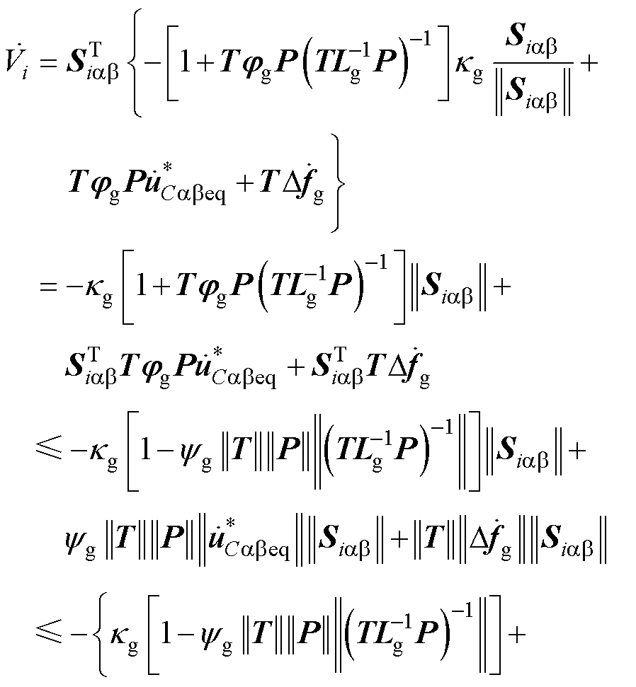
 (45)
(45)
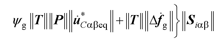
进一步将式(39)代入式(45)中可得
 (46)
(46)
由式(46)易知,所设计能够保证在有限时间收敛,且得益于的设计,使得切换控制项能够通过积分运算而连续化。至此,定理1得证。
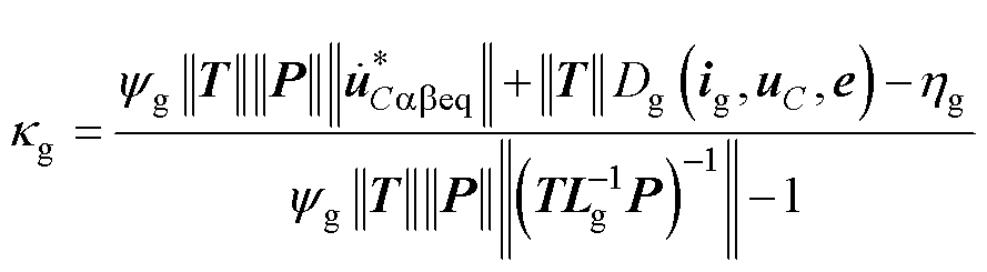
结合式(39)可知,时变增益κg会随GCI输出电流ig、电容电压uC以及网侧电压e的变化而变化。所设计STSMC控制器实现了对输出ig及uC的闭环控制,以及对网侧电压e的周期性采样。故通过图7中的反馈调节可实现控制增益对系统内外参数扰动的自适应性,从而避免了因传统固定控制增益造成的系统的输出能量波动与过度响应(波形比较详见附图2)。
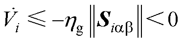
定理2:式(35)~式(39)中所设计的STSMC控制器,能够确保电流状态沿在时间tr≤||Siab(0)||/hg内稳定收敛。
证明:式(46)中的Lyapunov方程可重写为
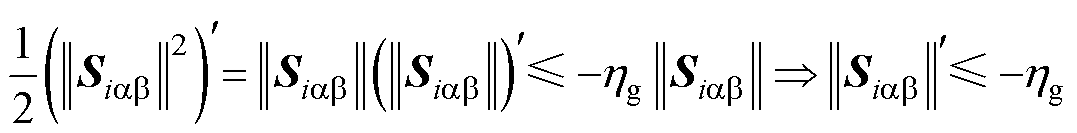 (47)
(47)
对式(47)两边同时积分得到
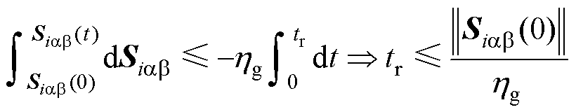 (48)
(48)
当电流状态到达 ,由式(35)可得
 (49)
(49)
由式(49)易知,电流状态将沿着
 在时间tr内到达原点。至此,定理2得证。
值得注意的是,式(36)中设计的虚拟控制律,也是交流电压内环的输入参考值。决定了 的收敛基准,并直接影响到电压内环的输出性能,由此充当了虚拟控制律的角色。
从式(14)中的电流模型可以看出,GCI系统的实际控制量为 。故需利用交流电压内环将式(36)中的虚拟控制律转换为。图8给出了交流电压内环STSMC内环控制结构。
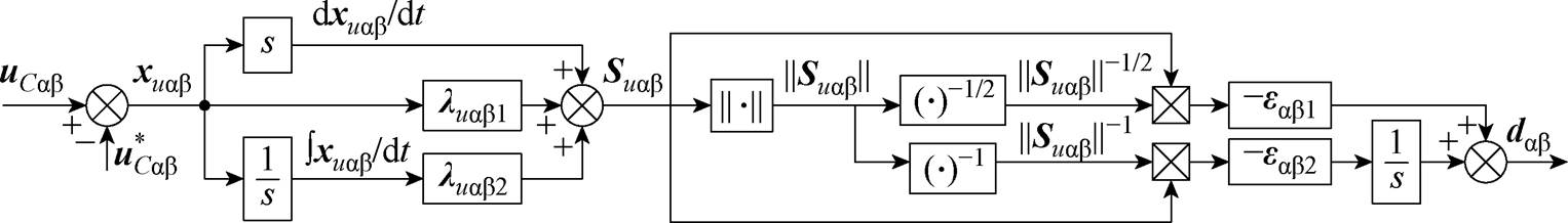
图8 交流电压内环控制结构
Fig.8 Structure of the AC voltage inner loop
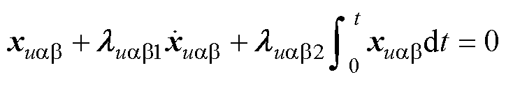
定义交流电压内环的输入误差为状态变量,即
 (50)
(50)
式中, 为定理2中的虚拟控制律。
对式(50)求导后,得到电压误差的变化率为
 (51)
(51)
设计电压状态滑模面为
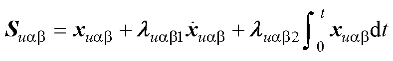 (52)
(52)
式中,滑模面 ;
; ;
; ,且
,且 、
、 、
、 、
、 >0。
>0。
结合式(51)可知,控制律存在于 的一阶导数上,故对式(52)求导可得
 (53)
(53)
式中,hg、bg为不确定项,且满足
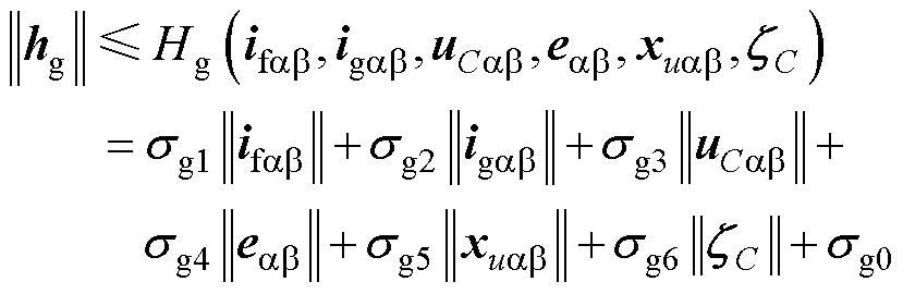 (54)
(54)
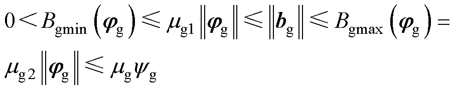 (55)
(55)
式中,sgz(z=0, 1, 2, 3, 4, 5, 6)>0与mgv(v=1, 2)均表示不确定项的边界值;Hg(ifab, igab, uCab, eab, xuab)与Bgmax(jg)、Bgmin(jg)分别为hg与bg的边界函数。
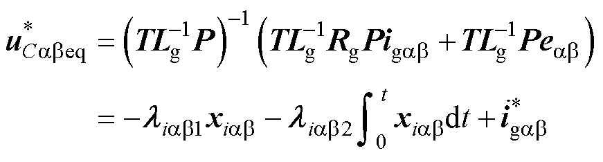
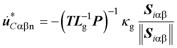
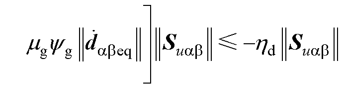
定理3:对于式(50)中构造的电压状态xCab与式(52)中的滑模面Suab,如式(56)所示的控制律 能够保证
能够保证 沿
沿 快速稳定收敛至原点。
 (56)
(56)
 (57)
(57)
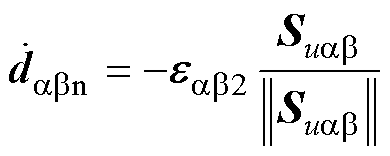 (58)
(58)
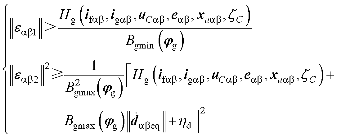 (59)
(59)
式中,dabeq与dabn分别为等效与切换控制律;eab1=diag(ea1, eb1)、eaβ2=diag(ea2, eb2)表示控制律预估增益,且满足ea1、eb1、ea2、eb2>0;hd为调节参数,hd>0。
证明:设计Lyapunov方程Vu为
 (60)
(60)
对Vu求导并将式(53)~式(55)代入式 (60)得
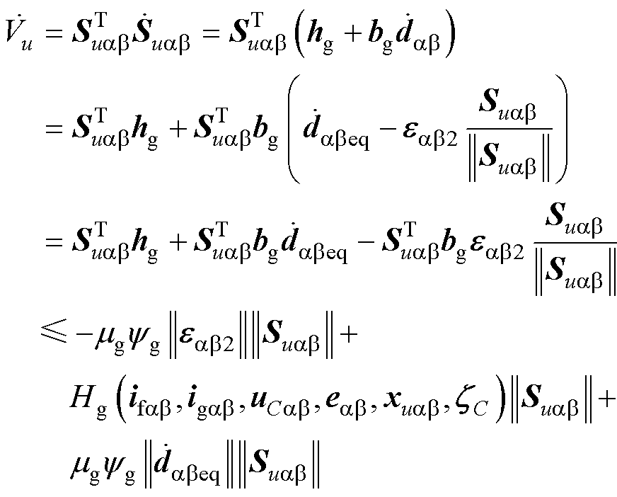 (61)
(61)
将式(59)中的增益预估范围代入式(61)得
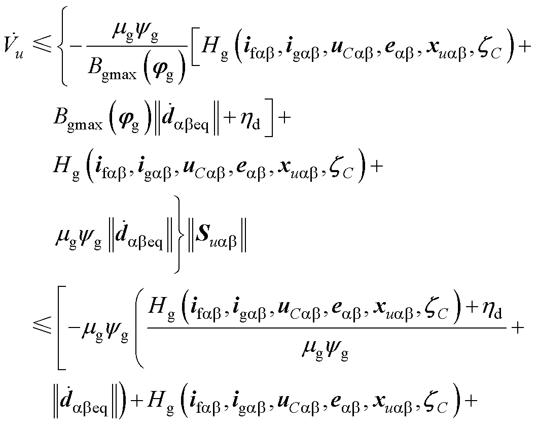
 (62)
(62)
当电压状态xCab到达后,可得
 (63)
(63)
由式(63)易知, 能够在的约束下沿着到达原点。且
 中包含的切换项能够通过积分运算实现连续化。至此,定理3得证。
为了验证本文所提方法的可行性,这里基于Matlab/Simulink平台搭建风力发电系统模型,并引入传统PI控制[8]、TSMC[20]与螺旋算法(Twisting Algorithm, TA)控制[28]与本文STSMC策略对比,以分析本文策略的优势,且为方便分析,分别用PI、TM、TW、ST表示各控制器下的系统输出曲线。电路模型参数与控制器参数分别见表1、表2。
表1 风力发电系统电路模型参数
Tab.1 WPGSs' circuit model parameters
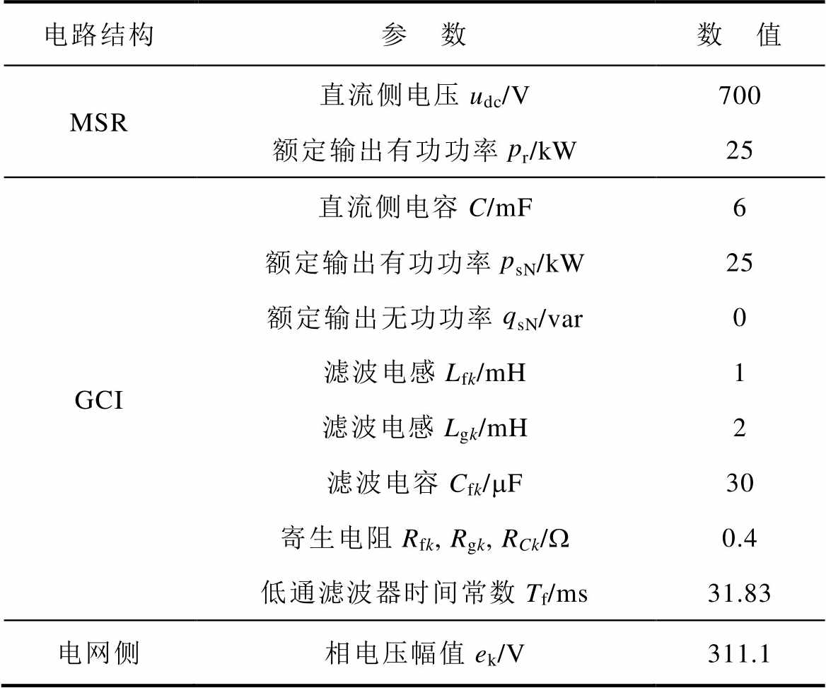
电路结构参 数数 值 MSR直流侧电压udc/V700 额定输出有功功率pr/kW25 GCI直流侧电容C/mF6 额定输出有功功率psN/kW25 额定输出无功功率qsN/var0 滤波电感Lfk/mH1 滤波电感Lgk/mH2 滤波电容Cfk/mF30 寄生电阻Rfk, Rgk, RCk/W0.4 低通滤波器时间常数Tf/ms31.83 电网侧相电压幅值ek/V311.1
表2 STSMC控制器参数
Tab.2 STSMC controller parameters

STSMC控制器参 数数 值 直流电压外环lU10.1 lU20.1 aU0.1 bU100 交流电流内环lia1, lia22 000 lib1, lib210 hg1 000 交流电压内环lua1, lua10.1 lub2, lub210 ea1, eb1170 ea2, eb2100 hd10
为分析在考虑式(2)中的参数扰动后,不同控制策略的输出性能,本文设计参数扰动环境下的系统输出性能仿真。为了更好地观察不同参数扰动对系统的影响,这里分为外部输入参考电压 扰动与内部LCL值扰动两种情况进行分析。
由于直流发电侧的参考电压值决定着GCI侧的注入功率参考值 ,故系统本身对的扰动克服至关重要,这直接决定着GCI能否向网侧提供稳定功率。保持表1与表2中其他参数不变,设定如下仿真过程:当t=0 s时,=700 V;当t=0.05 s时,=710 V;当t=0.1 s时,=690 V;当t=0.15 s时,=700 V。仿真结果如图9所示与见表3。
如图9a所示为GCI输出有功功率ps。易见ps(PI)的稳态误差为3 111.501 W,是ps(ST)的近4倍;且结合表3对比三种SMC策略,ps(ST)相较于ps(TM) 和ps(TW),稳态误差分别降低2/3与1/2。且ps(ST)实现了2.559 ms内的系统受扰后稳定,保证了GCI输出有功功率的快速稳定。
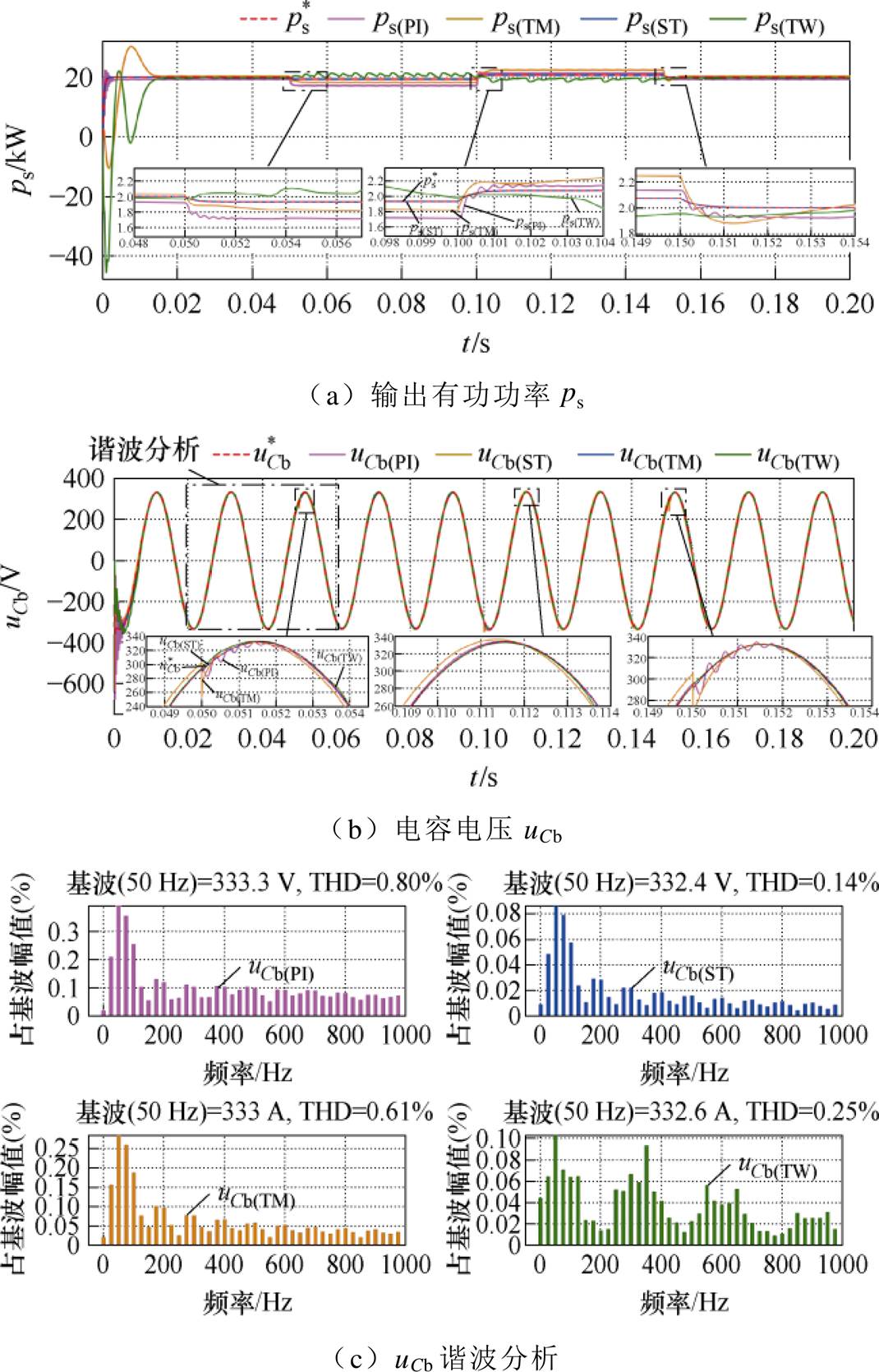
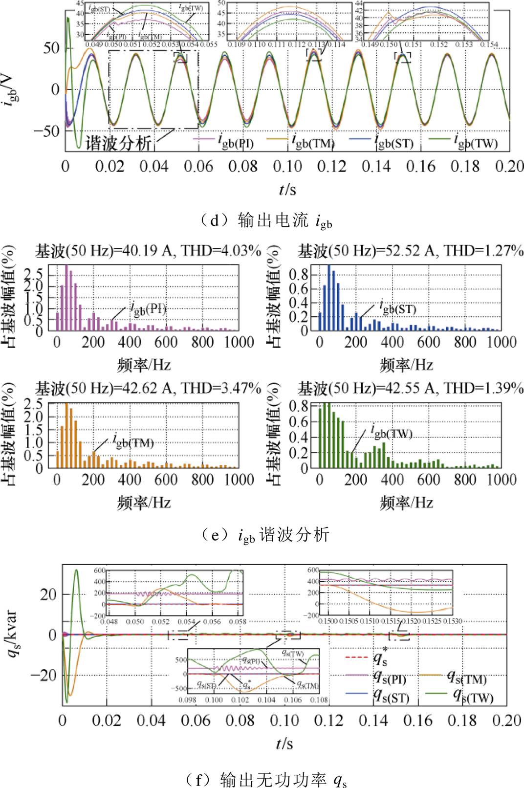
图9  扰动时系统输出性能分析
Fig.9 Analysis of system output performance when is disturbed
表3  扰动时各控制系统输出性能对比
Tab.3 Comparison of output performance of each control system when  is disturbed
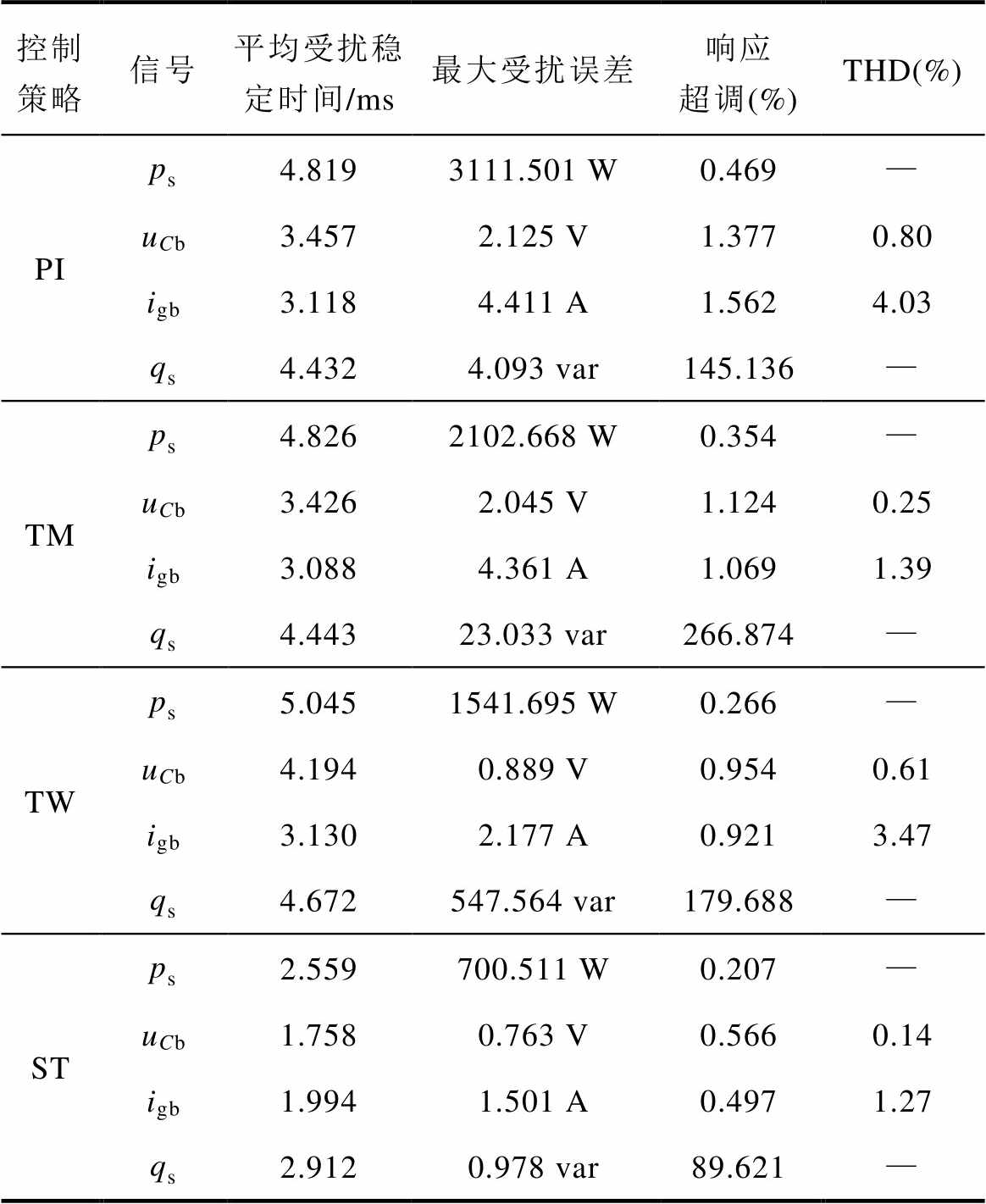
控制策略信号平均受扰稳定时间/ms最大受扰误差响应超调(%)THD(%) PIps4.8193111.501 W0.469— uCb3.4572.125 V1.3770.80 igb3.1184.411 A1.5624.03 qs4.4324.093 var145.136— TMps4.8262102.668 W0.354— uCb3.4262.045 V1.1240.25 igb3.0884.361 A1.0691.39 qs4.44323.033 var266.874— TWps5.0451541.695 W0.266— uCb4.1940.889 V0.9540.61 igb3.1302.177 A0.9213.47 qs4.672547.564 var179.688— STps2.559700.511 W0.207— uCb1.7580.763 V0.5660.14 igb1.9941.501 A0.4971.27 qs2.9120.978 var89.621—
观察图9b中的电压波形uCb,uCb(PI)在 受扰后出现明显振荡,暂态恢复时间为3.457 ms,相比uCb(ST)增加了2倍;且uCb(PI)的最大扰动偏差达到了2.125 V,是uCb(ST)的近2倍。再横向对比三种SMC策略,uCb(ST)受扰后的响应超调相比uCb(TM)与uCb(TW)分别减少0.558%和0.388%,进一步保证了图9c中uCb(ST)谐波含量仅为0.14%。图9d中所示的igb(ST)很好地继承了uCb(ST)的优点:当波动时,得益于交流电流内环STSMC的设计,igb(ST)的最大扰动偏差仅为1.501 A,是igb(TW)的近1/2,igb(PI)与igb(TW)的近1/3,有效地降低了图9e中igb(ST)的谐波含量;且igb(ST)的受扰恢复时间仅为1.994 s,这种快速的动态响应性能也是保证ps(ST)动态性能的关键。由此可看出,STSMC策略能够有效提升GCI应对风力发电侧波动的鲁棒性能。
所设计STSMC的优越性能在图9f所示的qs波形中进一步得到验证。当波动时,qs(PI)、qs(TM)及qs(TW)的响应超调分别达到了145.136%、266.874%与179.688%,而qs(ST)仅为89.621%,最大程度保证了GCI输出无功的稳定性。
针对图2中GCI侧LCL滤波器中的储能器件Lfk、Cfk、Lgk,保持表1与表2中其他参数不变,设置如下参数扰动过程:当t=0 s与t=0.2 s时,各元器件参数均为额定值,即Lfk=1 mH、Cfk=30 mF、Lgk= 1 mH且Rfk=0.5 W、RCk=0.5 W、Rgk=0.5 W;当t=0.05 s时,仅Lfk=0.75 mH、Rfk=0.6 W,其他元器件均为额定值;当t=0.1 s时,仅Cfk=22 mF、RCk=0.6 W,其他元器件均为额定值;当t=0.15 s时,仅Lgk=0.75 mH、Rgk=0.6 W,其他元器件均为额定值。仿真结果如图10所示与见表4。


图10 LCL扰动时系统输出性能分析
Fig.10 Analysis of system output performance when LCL is disturbed
如图10a所示为系统输出功率ps波形。结合表4易知,当LCL元器件参数波动时,ps(PI)的波形振荡恢复时间最长,达到了4.896 ms,是ps(ST)的近1.5倍;且ps(PI)的最大受扰误差达到了871.162 W,相比ps(ST)增加了61.978%。且ps(ST)同时克服了TM稳定时间长、TW扰动误差大这两个缺点,保证了LCL参数扰动情况下GCI输出功率的准确性。由图10b所示的输出无功曲线qs可知,qs(PI)受扰后的超调达到了779.778%,是qs(ST)的近10倍;qs(PI)的受扰稳定时间为4.144 s,是qs(ST)的近1.3倍。且qs(ST)相较于qs(TM)将受扰恢复时间缩短了23.51%,相较于qs(TW)将最大误差降低了89.92%。
表4 LCL扰动时各控制系统输出性能对比
Tab.4 Comparison of output performance of each control system when LCL is disturbed
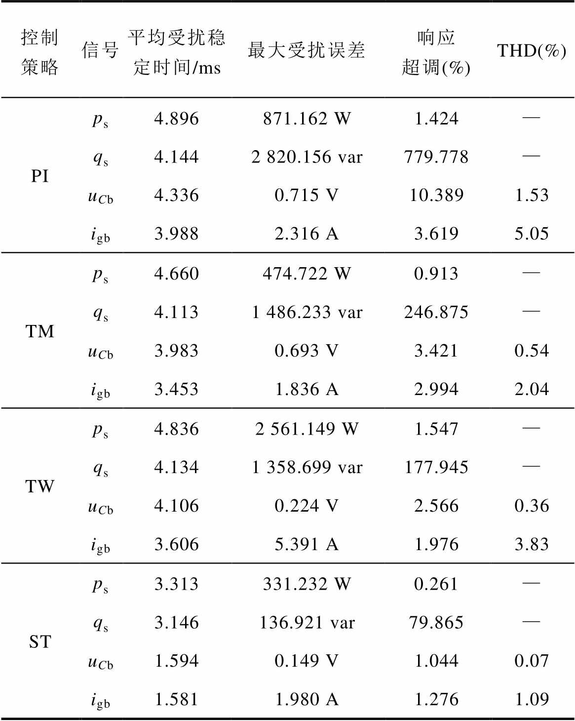
控制策略信号平均受扰稳定时间/ms最大受扰误差响应超调(%)THD(%) PIps4.896871.162 W1.424— qs4.1442 820.156 var779.778— uCb4.3360.715 V10.3891.53 igb3.9882.316 A3.6195.05 TMps4.660474.722 W0.913— qs4.1131 486.233 var246.875— uCb3.9830.693 V3.4210.54 igb3.4531.836 A2.9942.04 TWps4.8362 561.149 W1.547— qs4.1341 358.699 var177.945— uCb4.1060.224 V2.5660.36 igb3.6065.391 A1.9763.83 STps3.313331.232 W0.261— qs3.146136.921 var79.865— uCb1.5940.149 V1.0440.07 igb1.5811.980 A1.2761.09
观察图10c与图10d中的系统输出uCb、igb曲线,易见所设计STSTC策略实现了LCL参数扰动情况下的三相输出信号稳定。由式(3)中的GCI模型可知,LCL的参数扰动会造成GCI模型的内部参数误差,而STSTC算法不仅通过积分运算消除了传统SMC算法的抖振问题,且得益于式(35)与式(52)中积分项的引入,有效地消除了uCb、igb的稳态误差,缩短了二者的收敛时间,有效地降低了LCL的参数扰动对GCI系统稳定运行的影响。
本文基于dSPACE1006半实物仿真平台搭建实验机,如图11所示:包含一台20 kW的PMSG实验机、20 kW的整流器与GCI、并网模拟器。设置发电侧输出相电压幅值500 V,直流侧额定电压700 V,GCI输出额定三相电压幅值为311 V,输出额定有功功率与无功功率分别为10 kW与0 var,平台采样频率为10 kHz。GCI输出侧的LCL滤波器参数值可选:Lfk(2 mH, 1 mH)、Lgk(2 mH, 1 mH)、Cfk(30 mF, 25 mF)。
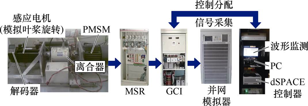
图11 基于dSPACE半实物仿真平台
Fig.11 dSPACE semi-physical simulation platform
实验中GCI输出功率不便测量,根据式(23)可知,其输出功率与电流igab呈正相关,故可利用dq变换,通过测量igdq来间接观察GCI的输出功率情况。且在表5中列出了GCI的关键输出参数,对本文提到的四种控制策略进行集中比较,以突出本文所设计的STSMC策略的优越性。
表5 参数扰动下各控制策略输出性能综合比较
Tab.5 Comprehensive comparison of output performance of each control strategy under parameter perturbation
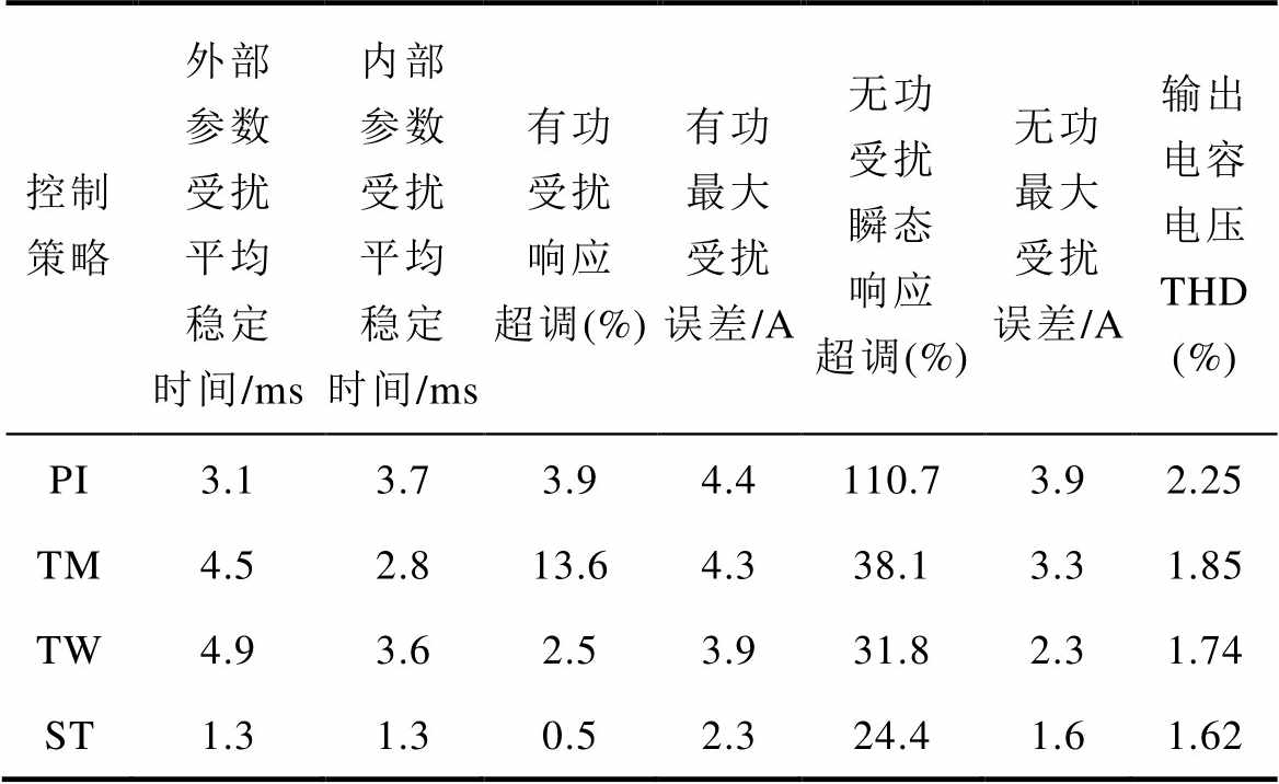
控制策略外部参数受扰平均稳定时间/ms内部参数受扰平均稳定时间/ms有功受扰响应超调(%)有功最大受扰误差/A无功受扰瞬态响应超调(%)无功最大受扰误差/A输出电容电压 THD (%) PI3.13.73.94.4110.73.92.25 TM4.52.813.64.338.13.31.85 TW4.93.62.53.931.82.31.74 ST1.31.30.52.324.41.61.62
注:由于实验过程中利用dq轴电流igdq来间接观察GCI的输出功率情况,故表中关于功率性能项的单位均为A;表中数据为内/外部参数受扰与恢复两个阶段的平均值。
1)外部参数扰动下的GCI性能分析
图3中,考虑GCI工作时的外部输入参数扰动。设置直流侧输入参考电压从700 V跳变至710 V,由此观察GCI的实际输出性能,四种控制策略的实验结果如图12所示。
由式(20)与式(21)分析可知,的增大一定程度上会导致GCI的输出功率ps降低。进一步观察图12a易见,PI控制下的GCI输出igd(PI)与uCk(PI)在受扰后的幅值变化量为4.4 A与2.6 V,响应时间达到3.1 ms,且稳态后纹波振荡明显,这表明传统PI策略应对外部参数扰动时的鲁棒性较弱。对比图12d中的本文策略,得益于式(39)中时变增益的设计,使得igd(ST)在扰动后仅降低了2.3 A,相较PI减少近1/2的电流损失,且STSMC在时变增益的调节下保持了快速收敛特性,使得igd(ST)的响应时间仅为1.3 ms,较PI减少了近1/3;上述交流电流内环的鲁棒调节进一步保证了交流电压内环输入参考信号的稳定性,uCk(ST)的幅值变化量仅为1.4 V,较PI降低近1/2;且式(59)中的可预估增益通过收敛范围的限制减少了uCk(ST)的收敛时间,使uCk(ST)在受扰后的1 ms内就能够达到稳定。由此证明,本文所提STSMC策略能够有效抑制直流侧电压波动对GCI的影响。

图12  扰动时系统输出性能分析
Fig.12 Analysis of system output performance when is disturbed
再横向对比三种SMC策略:图12b的TSMC策略相比本文策略,由于控制环增益固定,使得其在扰动后的igd(TM)产生10 A的超调响应,比igd(ST)增加48.9%,且uCk(TM)的幅值变化量相比uCk(ST)也增加近2倍;进一步观察igd(TM)波形,由于TSMC对控制环输出抖振抑制能力较弱,使得igd(TM)稳态幅值间歇性抖动,降低了GCI的并网电能质量。对比传统Twisting策略,由图12c看到,igd(TM)在扰动后的幅值波动明显,这主要是由于其电流内环增益固定造成的,且由于缺少对控制环增益范围的限制,使得igd(TM)与igq(TM)在受扰过程中会消耗更多控制能量,对GCI的硬件散热提出更高的要求。进一步结合表5可知,所提STSMC策略相比其他SMC策略,由于控制增益的先进性,同时实现了最短的受扰恢复时间与最小的有功受扰误差,GCI输出电容电压谐波含量仅为1.62%,显著增强了受外部参数扰动的GCI的鲁棒性能与输出动静态特性。值得注意的是,上述波形变化趋势与图9中的仿真结果基本保持一致,但受实际实验环境的影响,使得实验值相比理想仿真值略有差异。
2)内部参数扰动下的GCI性能分析
图3中,考虑GCI工作时的内部参数扰动。在图11中,调整LCL滤波器参数,为方便观察,在同一时刻设置Lfk与Lgk由2 mH跳变至1 mH、Cfk由30 mF跳变至25 mF。实验结果如图13所示。
由式(3)可知,LCL的参数扰动会直接影响GCI模型内部的信号变化。图13a中,PI控制下的GCI输出电流igq(ST)在LCL参数受扰后波形振荡明显,变化量达到3.9 A,其响应时间达到3.7 ms;且这种变化后的惯性振荡在uCk中同样体现,表明传统PI控制策略并无法保证内部参数扰动下的GCI输出性能。对比图13d中的本文所提策略,igq(ST)在参数扰动后的变化量仅为1.6 A,相比PI降低近2.5倍;其响应时间仅为1.3 ms,相比PI降低近3倍;这证明所设计交流电流内环时变增益与交流电压内环预估增益使得STSMC的强鲁棒性得到充分展现,且式(2)中内部参数扰动量的考虑保证了STSMC能够更好地应对LCL滤波器的参数波动,实现了内部器件参数扰动时的系统输出功率的稳定。进一步结合表5对比三种SMC策略,本文所提策略由于在控制环中引入时变增益与可预估增益,有效避免了传统TSMC算法因过量估计控制增益而对GCI造成的能量损耗与不稳定振荡,降低了46.3%与51.5%的有功与无功受扰误差;同样也减少了传统Twisting策略近68.4%的动态响应时间,提升了内部参数扰动下GCI的输出性能。

图13 LCL扰动时系统输出性能分析
Fig.13 Analysis of system output performance when LCL is disturbed
本文针对应用于WPGS的GCI系统受内外参数扰动后暂态性能差、稳态波动性强的问题,提出了一种抗参数扰动的积分型STSMC策略,以提升GCI的输出性能与抗扰鲁棒性。通过理论分析与设计、多工况仿真和实验对比,相比于传统PI控制和传统SMC策略,得出如下结论:
1)在系统模型和控制器设计中同时考虑了匹配和非匹配参数扰动,进而保证了系统的鲁棒性,输出功率受扰误差相比传统PI控制减少了79.55%。
2)传统SMC策略中的切换项通过STSMC的积分器运算而连续化,有效避免了抖振现象;且在内外参数扰动下,与传统TSMC与Twisting策略对比,本文控制策略使GCI的输出功率纹波幅值分别降低了25.4%和52.72%。
3)在直流电压外环中设计可预估控制增益,以替换传统PI控制中的过度增益,实现了直流链路输出功率参考值误差降低0.15%,且结合所引入积分项的调控作用进一步确保了交流内环的控制精度;在交流电流内环控制器中设计时变控制增益,以减少参数扰动下不必要的能量损耗,进而将GCI输出电容电压与电流谐波含量降低0.27%和5.62%,且将输出功率误差限制在4.92%。
上述控制特性对WPGS中GCI系统的稳定运行提供了可行方案。在未来的研究工作中,将进一步考虑GCI开关损耗与电网侧谐波对控制系统的实际影响,建立更加完整的GCI数学模型;并进一步考虑不平衡电网下本控制策略的拓展性设计。
附 录
附图1与附图2对应文中图9工况,分别展示了传统TSMC策略、Twisting策略以及本文所提STSMC策略的交流电流/电压内环SMC控制器输出性能比较,能够进一步验证所引入时变增益与可预估增益应对参数扰动的有效性。

附图1 交流电流内环STSMC性能曲线
App.Fig.1 AC current inner loop STSMC performance curves

附图2 交流电压内环STSMC性能曲线
App.Fig.2 AC voltage inner loop STSMC performance curves
由于电网侧谐波会影响式(1)中GCI模型的控制精度与输出性能。故这里利用仿真模拟系统稳态后,t=0.05 s时网侧出现占基波幅值15%的3次谐波与10%的5次谐波的情况,以验证STSMC策略对GCI的鲁棒控制。仿真结果如附图3与附图4所示。
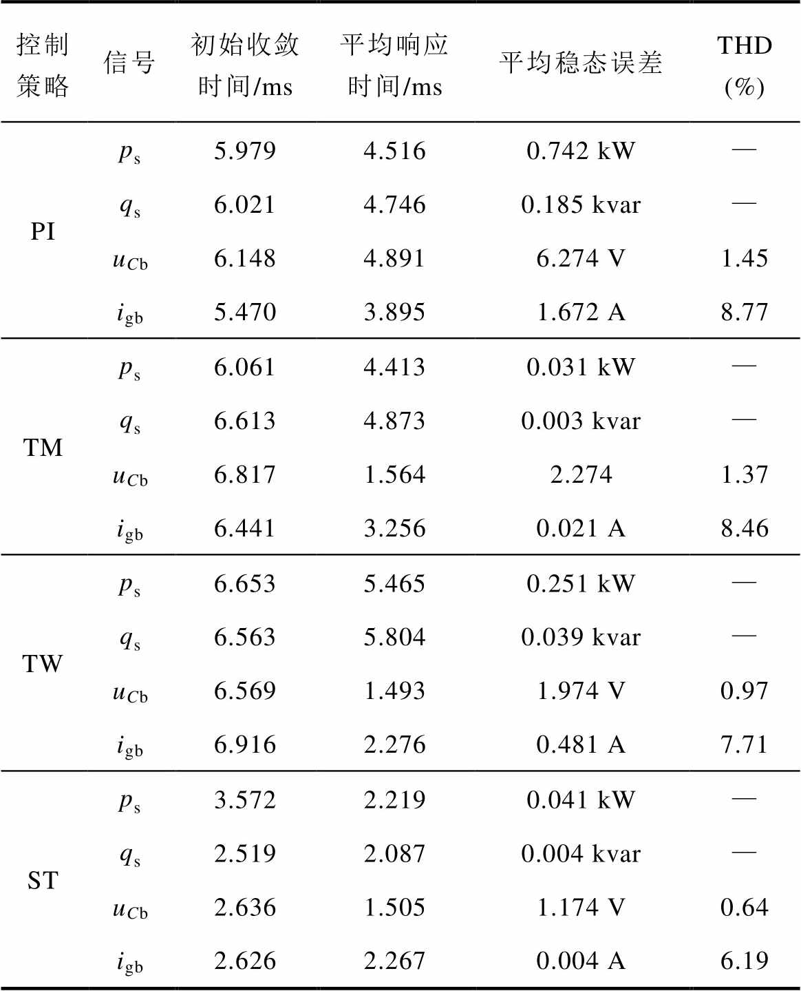
附表1与附图5给出了模拟WPGS发电侧风速快速变化造成GCI输入侧功率波动时(当t=0 s时, 保持额定值为20 kW;当
 时,上升至25 kW;当
 时,下降至15 kW;当
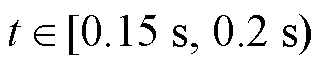 时,恢复额定值20 kW),不同控制策略的输出性能比较结果,以更全面地展现本文所提STSMC策略的强鲁棒性。

附图3 网侧谐波影响下各策略输出电流性能比较
App.Fig.3 Comparison of output current performance of each strategy under the influence of network side harmonics

附图4 网侧谐波影响下各策略输出电容电压性能比较
App.Fig.4 Comparison of output voltage performance of each strategy under the influence of network side harmonics
式(8)~式(12)中不确定项的范围在参考文献[22-25]后,确定GCI的电感参数扰动值为标称值的-25%、电容参数扰动值为标称值的-27%、寄生电阻参数扰动值为标称值的+10%、电压/电流信号波动值取其额定值的+5%。由此对应式(8)~式(11)给出如下扰动项边界常数范围确定公式为
附表1 输入功率扰动下各控制策略输出性能比较
App.Tab.1 Comparison of output performance of each control strategy under input power disturbance
控制策略信号初始收敛时间/ms平均响应时间/ms平均稳态误差THD (%) PIps5.9794.5160.742 kW— qs6.0214.7460.185 kvar— uCb6.1484.8916.274 V1.45 igb5.4703.8951.672 A8.77 TMps6.0614.4130.031 kW— qs6.6134.8730.003 kvar— uCb6.8171.5642.2741.37 igb6.4413.2560.021 A8.46 TWps6.6535.4650.251 kW— qs6.5635.8040.039 kvar— uCb6.5691.4931.974 V0.97 igb6.9162.2760.481 A7.71 STps3.5722.2190.041 kW— qs2.5192.0870.004 kvar— uCb2.6361.5051.174 V0.64 igb2.6262.2670.004 A6.19
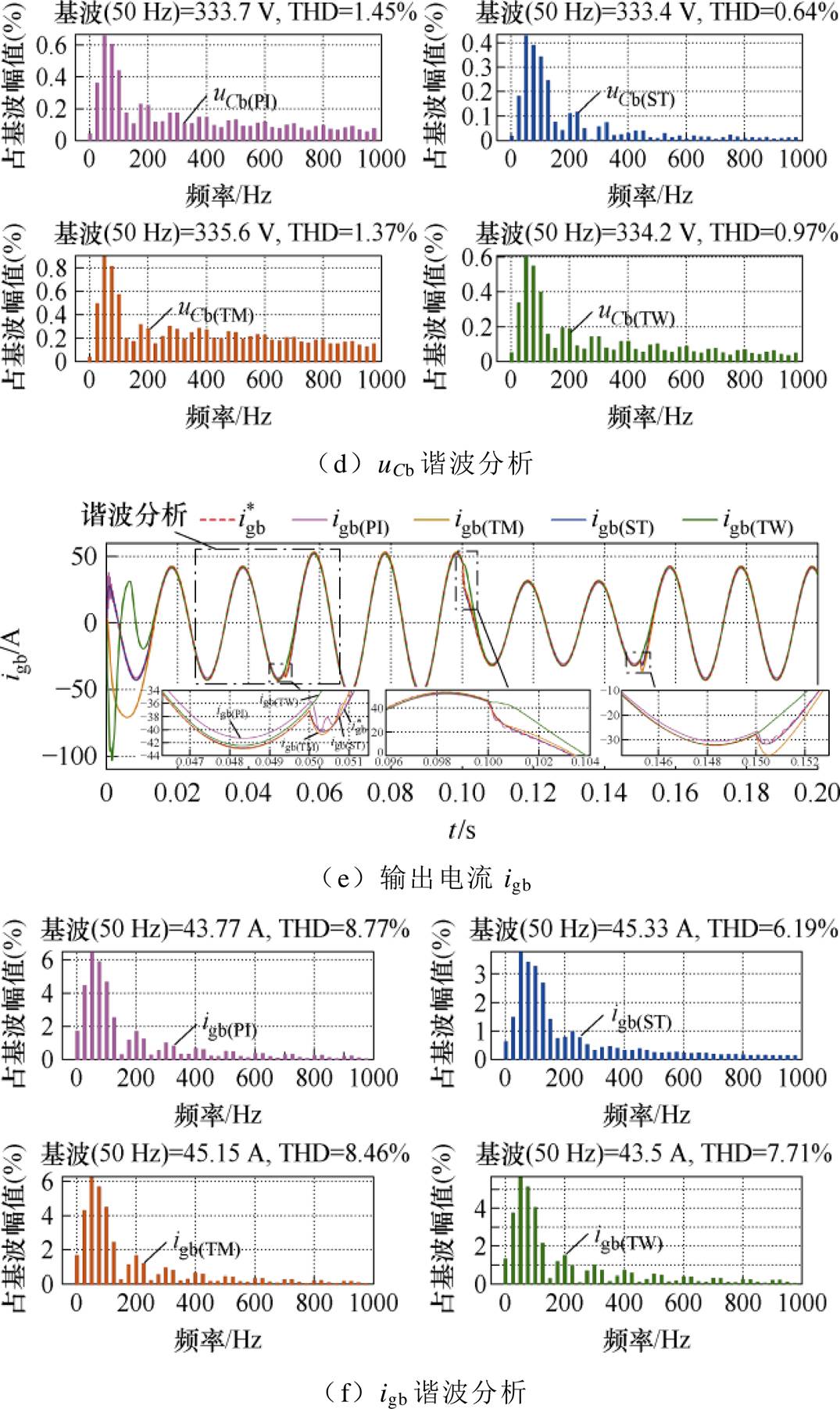
附图5 输入功率扰动下系统输出性能结果
App.Fig.5 Output performance of the system under input power disturbance
 (A1)
(A1)
 (A2)
(A2)
 (A3)
(A3)
参考文献
[1] 张祥宇, 黄泳漩, 付媛. 非线性弹性耦合下双馈风电机组的暂态能量转移与振荡特性分析[J]. 电工技术学报, 2024, 39(13): 3956-3974.
Zhang Xiangyu, Huang Yongxuan, Fu Yuan. Transient energy transfer and oscillation characteri- stics analysis of doubly-fed wind turbine under nonlinear elastic coupling[J]. Transactions of China Electrotechnical Society, 2024, 39(13): 3956-3974.
[2] 刘昊, 方天治, 张惠丽, 等. 弱电网下应对复杂稳定性问题的并网逆变器改进电压前馈通路研究[J]. 电工技术学报, 2024, 39(16): 4955-4967.
Liu Hao, Fang Tianzhi, Zhang Huili, et al. Research on an improved voltage feedforward path of grid- connected inverter coping with complex stability issues in weak grid[J]. Transactions of China Elec- trotechnical Society, 2024, 39(16): 4955-4967.
[3] Liu Jianhong, Cheng Jiesheng. Online voltage security enhancement using voltage sensitivity-based coherent reactive power control in multi-area wind power generation systems[J]. IEEE Transactions on Power Systems, 2021, 36(3): 2729-2732.
[4] Mahdavi M, Jurado F, Schmitt K, et al. Electricity generation from cow manure compared to wind and photovoltaic electric power considering load uncer- tainty and renewable generation variability[J]. IEEE Transactions on Industry Applications, 2024, 60(2): 3543-3553.
[5] 洪国庆, 吴国旸, 金宇清, 等. 电力系统风力发电建模与仿真研究综述[J]. 电力系统自动化, 2024, 48(17): 22-36.
Hong Guoqing, Wu Guoyang, Jin Yuqing, et al. Review on research of modeling and simulation for wind power generation in power system[J]. Auto- mation of Electric Power System, 2024, 48(17): 22-36.
[6] 李啸骢, 罗雪丽, 侯立亮, 等. 基于分数阶LCL滤波器的风力发电网侧控制研究[J]. 太阳能学报, 2022, 43(12): 383-391.
Li Xiaocong, Luo Xueli, Hou Liliang, et al. Research on grid-side control of wind power generation based on fractional LCL filter[J]. Acta Energiae Solaris Sinica, 2022, 43(12): 383-391.
[7] Chow J H. Enabling inverter-based resource stability control in power systems with high renewable penetration[J]. CSEE Journal of Power and Energy Systems, 2023, 9(3): 1248-1250.
[8] Sung W Y, Ahn H M, Oh C Y, et al. Design and control of a bidirectional power conversion system with 3-level T-type inverter for energy storage systems[J]. Journal of Electrical Engineering & Technology, 2018, 13(1): 326-332.
[9] Ebrahimi J, Eren S. A multi-source DC/AC converter for integrated hybrid energy storage systems[J]. IEEE Transactions on Energy Conversion, 2022, 37(4): 2298-2309.
[10] Lai Jinmu, Yin Xin, Yin Xianggen, et al. Fractional order harmonic disturbance observer control for three-phase LCL-type inverter[J]. Control Engin- eering Practice, 2021, 107: 104697.
[11] Liang Weihua, Liu Yushan, Ge Baoming, et al. DC-link voltage balance control strategy based on multidimensional modulation technique for quasi- Z-source cascaded multilevel inverter photovoltaic power system[J]. IEEE Transactions on Industrial Informatics, 2018, 14(11): 4905-4915.
[12] Sellali M, Betka A, Djerdir A, et al. A novel energy management strategy in electric vehicle based on H∞ self-gain scheduled for linear parameter varying systems[J]. IEEE Transactions on Energy Conversion, 2021, 36(2): 767-778.
[13] 周汉斌, 杨建, 黄连生, 等. 基于有限状态机的三电平逆变器双矢量模型预测控制策略[J]. 电力系统自动化, 2023, 47(11): 155-164.
Zhou Hanbin, Yang Jian, Huang Liansheng, et al. Double-vector model predictive control strategy of three-level inverter based on finite state machine[J]. Automation of Electric Power Systems, 2023, 47(11): 155-164.
[14] 任志玲, 叶俊, 王继超. 三相并网逆变器改进定频模型预测电流控制[J]. 电源学报, 2023, 21(4): 88-96.
Ren Zhiling, Ye Jun, Wang Jichao. Model predictive current control with improved fixed-frequency for three-phase grid-connected inverter[J]. Journal of Power Supply, 2023, 21(4): 88-96.
[15] 施建强, 李双, 赵宁宁, 等. 基于神经网络的逆变器约束自适应PI控制[J]. 太阳能学报, 2023, 44(10): 19-27.
Shi Jianqiang, Li Shuang, Zhao Ningning, et al. Constrained adaptive PI control of inverter based on neural network[J]. Acta Energiae Solaris Sinica, 2023, 44(10): 19-27.
[16] 许水清, 许晓凡, 何怡刚, 等. 基于自适应滑模观测器的中点钳位型三电平并网逆变器开关管和电流传感器故障诊断[J]. 电工技术学报, 2024, 39(13): 4066-4078.
Xu Shuiqing, Xu Xiaofan, He Yigang, et al. A diagnosis method for power switch and current sensor faults in grid-connected three-level neutral-point clamped inverters based on adaptive sliding mode observer[J]. Transactions of China Electrotechnical Society, 2024, 39(13): 4066-4078.
[17] Tran T V, Kim K H, Lai J S. H2/H∞ robust observed- state feedback control based on slack LMI-LQR for LCL-filtered inverters[J]. IEEE Transactions on Industrial Electronics, 2023, 70(5): 4785-4798.
[18] Heydari R, Young H, Flores-Bahamonde F, et al. Model-free predictive control of grid-forming inver- ters with LCL filters[J]. IEEE Transactions on Power Electronics, 2022, 37(8): 9200-9211.
[19] Prasad M V S. Design and implementation of model parameter independent robust current control scheme of three-phase inverter-a neural network-based classification approach[J]. CPSS Transactions on Power Electronics and Applications, 2024, 9(2): 166-174.
[20] Zhao Zhenhua, Yang Jun, Li Shihua, et al. Continuous output feedback TSM control for uncertain systems with a DC-AC inverter example[J]. IEEE Transa- ctions on Circuits and Systems II: Express Briefs, 2018, 65(1): 71-75.
[21] Liu Xiangjie, Wang Ce, Kong Xiaobing, et al. Tube- based distributed MPC for load frequency control of power system with high wind power penetration[J]. IEEE Transactions on Power Systems, 2023, 39(2): 3118-3129.
[22] Fu Cheng, Zhang Chenghui, Zhang Guanguan, et al. Current sensorless sliding-mode voltage control for LC filtered three-level T-type inverters[J]. IEEE Transactions on Circuits and Systems II: Express Briefs, 2024, 71(4): 2264-2268.
[23] Liu Zhongqian, Wu Hongbin, Jin Wei, et al. Two-step method for identifying photovoltaic grid-connected inverter controller parameters based on the adaptive differential evolution algorithm[J]. IET Generation, Transmission & Distribution, 2017, 11(17): 4282- 4290.
[24] Tran T V, Kim K H, Lai J S. Optimized active disturbance rejection control with resonant extended state observer for grid voltage sensorless LCL-filtered inverter[J]. IEEE Transactions on Power Electronics, 2021, 36(11): 13317-13331.
[25] Yuan Xin, Xie Shuangchun, Chen Jiahao, et al. An enhanced deadbeat predictive current control of SPMSM with linear disturbance observer[J]. IEEE Journal of Emerging and Selected Topics in Power Electronics, 2022, 10(5): 6304-6316.
[26] 彭寥廓, 陈艳慧. 单相全桥离网逆变器输出侧功率解耦电路研究[J]. 电气技术, 2022, 23(1): 42-48, 55.
Peng Liaokuo, Chen Yanhui. Research on a single- phase full-bridge off-grid inverter with active power decoupling circuit at output side[J]. Electrical Engineering, 2022, 23(1): 42-48, 55.
[27] Gong Cheng, Sou W K, Lam C S. Reinforcement learning based sliding mode control for a hybrid- STATCOM[J]. IEEE Transactions on Power Elec- tronics, 2023, 38(6): 6795-6800.
[28] Kandil M S, Dubois M R, Bakay L S, et al. Application of second-order sliding-mode concepts to active magnetic bearings[J]. IEEE Transactions on Industrial Electronics, 2018, 65(1): 855-864.
Abstract In the burgeoning field of clean wind energy, integrating wind power generation systems (WPGSs) into the power grid has become a critical area of research and development. The performance and reliability of the grid-connected inverter (GCI) play a pivotal role in ensuring efficient and stable electricity supply from wind farms. However, the GCI often faces parameter disturbances during operation, which are exacerbated by fluctuations on both the generation side and the grid side, significantly impacting the quality of grid connection and the overall performance of the WPGSs. However, current GCI control approaches neglect disturbance parameters and compromise the system's resilience and stability, making it vulnerable to operational unpredictability. Therefore, a novel approach is introduced, considering the GCI's typical internal and external parameter perturbations. A robust control system is developed using the continuous higher-order super-twisting sliding mode control (STSMC) strategy.
The specific design method of the STSMC strategy for the GCI system is as follows. Firstly, a model of the GCI system is constructed with a DC voltage outer loop, an AC current inner loop, and an AC voltage inner loop, considering DC bus instantaneous power fluctuations and internal parameter disturbances of the GCI. Compared with the traditional PI strategy, the designed parameter perturbation model effectively suppresses internal parameter disturbances in the GCI when paired with the STSMC. Additionally, the design of the DC voltage outer loop has successfully stabilized the DC input power of the GCI, thereby reducing the impact of disturbances on the WPGS generation side on the performance of the GCI. Secondly, the integral-type STSMC controllers with time-varying and predictable gains are constructed for the GCI current and voltage loops. Thus, the interaction power between the GCI and the grid side can be controlled, and energy loss from excessive control gain caused by system uncertainty boundaries can be improved. Compared with the traditional terminal sliding mode control (TSMC) and Twisting algorithm SMC, the time-varying gain of the current loop helps the STSMC overcome the slow current response speed inherent in the Twisting algorithm. Moreover, the predictable gain of the voltage loop produces a smaller steady-state error than the TSMC. Finally, the stability and finite-time convergence of the proposed control strategy are proved based on Lyapunov theory.
Simulations and experiments are designed considering parameter disturbances under multiple conditions. The STSMC system exhibits a 79.55% reduction in output power disturbance error compared to PI control, with the output power ripple amplitude lowered by 25.4% and 52.72% compared to TSMC and Twisting, respectively. The designed predictable gain and integral control term reduce the harmonic content of the GCI output capacitor voltage and current by 0.27% and 5.62%. The adoption of time-varying control gain further constrains the output power error to within 4.92% and 0.15%. In subsequent research, the investigation will be expanded to account for the practical influence of switching losses within the GCI and the effects of grid-side harmonics on the control system, aiming to construct a complete mathematical model of the GCI. Furthermore, the strategy's adaptability for application under unbalanced grids will be examined in depth.
keywords:Grid-connected inverters, Super-Twisting algorithm, wind power system, parameter perturbation, integral type sliding mode
DOI: 10.19595/j.cnki.1000-6753.tces.241991
中图分类号:TM464
国家自然科学基金项目(52238002, 52277006)、港口自发电集装箱码头智能微电网关键技术研究项目(2023-ZGKJ-ZDYF-03)和哈尔滨市科技创新人才项目(RC2024DY395)资助。
收稿日期 2024-11-08
改稿日期 2024-12-15
张伟琦 男,1997年生,博士研究生,研究方向为可再生能源发电系统并/离网机制、储能电力变换器的非线性控制策略。E-mail: zwq1191678801@163.com
王艳敏 女,1983年生,副教授,博士生导师,研究方向为电气系统的优化控制、建筑信息化与智能化控制。E-mail: wangyanmin@hit.edu.cn(通信作者)
(编辑 陈 诚)