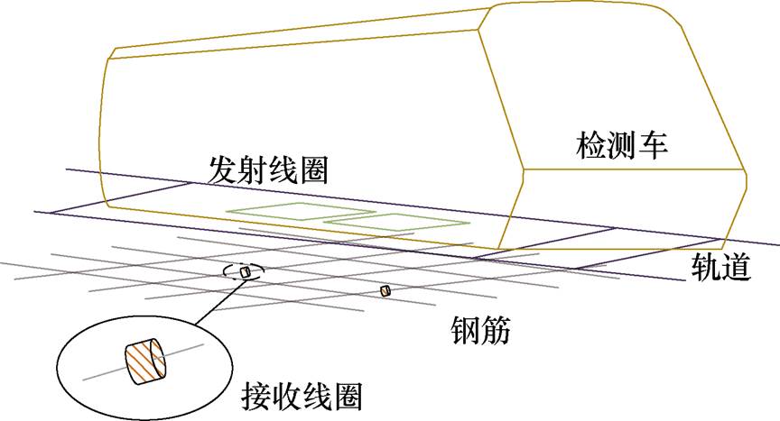
图1 所提出系统立体结构示意图
Fig.1 Diagram of the 3D structure of the proposed system
摘要 在轨道交通领域,将发射线圈安装于检测车底部,在检测车通过时采用无线供电技术,向地下的接收线圈辐射能量,从而对预埋传感器进行非接触供电,满足预埋传感器周期性供电,保障传感器长期不间断工作。但由于能量传输距离不同以及发射线圈的电流方向和线圈间距不同,会导致接收端获取能量变化。为此,该文提出一种基于等效功率分析的动态无线供电系统发射线圈电流及间距参数优化方法。首先,对发射端与接收端之间的互感进行计算。然后,定义等效功率,针对预埋传感器所埋深度的不同,对发射线圈的电流方向和线圈间距进行优化,得到能使传感器获取最大能量的线圈参数。最后,搭建实验原理样机验证所提方法的可行性和有效性,发射线圈尺寸为150 mm×150 mm,副边线圈紧密绕在直径12 mm的钢筋上,在发射端和接收端相距为150 mm时,以7 m/s的速度为例,采用参数优化后电流方向相反的线圈相较于优化前电流同向的线圈可提升50%的输出能量,达到0.14 W·s,满足传感器长期供电需求。
关键词:预埋传感器 动态无线供电 参数优化 最大等效功率
在轨道交通领域,预埋传感器由于其功耗低(几十至几百毫瓦)、尺寸小[1],在结构健康监测[2]中发挥着巨大作用,它们预埋于路基的混凝土中,涉及加速度计、温湿度计、应变计等多种传感器,可实时获取相应的关键状态信息,针对路基变形、边坡失稳、桥隧破坏等危害的发生及时预警,这对于隧道、桥梁等大型土木工程结构乃至轨道交通沿线路基的维护、管理等至关重要[3]。持续可靠的供电是预埋传感器正常工作的基本前提,但电池寿命有限,无法保证预埋在钢筋混凝土中的传感器长期稳定工作;也有采用有线供电的方式,但线路也需预埋进混凝土中,移动性有限且容易损坏[4]。相较而言,无线供电方式便于安装、易于重新部署,还可以大大减少施工机械操作的干扰,为预埋传感器无线可靠供电提供了新思路[5-7]。
将发射线圈安装于检测车底部,接收线圈置于铁路沿线的预埋传感器周围,如图1所示,当检测车通过时,高频电源将电源注入发射线圈,产生交变磁场,辐射能量至地下,沿途储能装置通过接收线圈获取能量。对于动态无线供电,大多是将发射线圈预埋于地下,为搭载接收线圈的移动设备供电,现有研究可以归纳为从控制策略[8-9]、磁耦合机构设计优化[10-12]、电磁兼容[13-15]等方面提升系统供电平稳性、传输效率。例如,K. Ukita等[11]通过设计DD- DDQ(double-D-double-D quadraure)线圈尺寸、匝数等提高系统的输出功率,扩大电动汽车充电区域。也有通过发射线圈与接收线圈之间互感的变化来调整重叠DD(double-D)线圈阵列中电流方向[12],以提高系统传输效率。H. Jafari等[16]利用算法对双极板(Bipolar Pads, BPP)线圈结构参数进行优化设计,增强系统的抗偏移性。但这些研究多用于大功率用电设备,接收端尺寸与发射线圈尺寸相当,同时在检测车移动过程中传输能量的冲击特性会影响平稳输出,不适用于预埋传感器动态无线供电[17]。在预埋传感器无线供电的研究中,美国佛罗里达国际大学研究团队[18]借助钢架搭建多个线圈并埋入混凝土,既作接收也作中继,使多个接收均能获取相同功率。Qian Libo等[19]通过强耦合磁共振,寻找为埋入混凝土中传感器供电的最优传输距离。但这些方法都是在静态下为传感器供电,通过动态供电的方式目前尚处于起步阶段。
图1 所提出系统立体结构示意图
Fig.1 Diagram of the 3D structure of the proposed system
基于此,针对检测车行驶速度快、接收端尺寸小造成的预埋传感器在短时间内获取能量有限的问题,提出了一种基于等效功率分析的动态无线电能传输系统发射线圈参数优化方法,使得接收端获取能量最大化,为轨道交通领域预埋传感器的可靠供电提供有效方案。首先,介绍了所提出动态无线供电系统结构及所采用的电路拓扑。其次,围绕钢筋结构,分析其自身参数,并进行钢筋与发射端间互感计算,得到发射线圈与接收线圈间互感关系。然后,分析电路拓扑,结合计算的互感,得到等效功率表达式,并分析所讨论DD线圈电流方向及线圈间距对其的影响,总结得到规律。最后,对所提出动态无线供电系统的等效功率计算方法进行实验验证。
发射线圈安装在检测车底部,由于受到铁轨的约束,不产生横向偏移,故不对此作讨论。所提出系统立体结构示意图如图1所示,钢筋铺设在轨道板中,在铁轨下方,主要考虑发射线圈在正对钢筋回路时与下方钢筋网络之间耦合获取的能量。
考虑到发射线圈与钢筋的耦合,线圈设计为正方形,并与钢筋环的大小一致。基于前期研究成果,当发射线圈产生磁场时,钢筋中会产生涡流,将接收线圈绕在软磁片制成的软磁心上,再紧绕在钢筋上利用其涡流获取能量[20]。系统结构简化示意图如图2所示,G为DD线圈中两个线圈之间的距离,LT和lJ分别为发射线圈和钢筋环的边长,均为150 mm,与实际应用相符,以一组发射线圈为例进行分析。
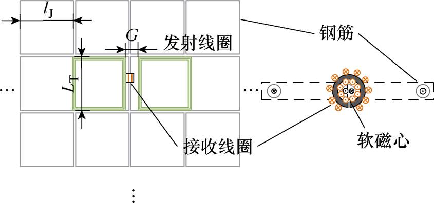
图2 系统结构简化示意图
Fig.2 Diagram of simplified system structure
所提出系统采用LCC-S(inductor-capacitor- capacitor-series),拓扑电路如图3所示。图中,LP、LS分别为发射和接收线圈的自感,L1、C1、C2构成原边LCC补偿,CS为接收线圈的串联谐振电容,CO为整流桥输出滤波电容,RS为接收线圈的内阻,UIN为输入的恒压源,IP、IS分别为发射线圈和接收线圈电流,IIN、VP分别为逆变输出电流和电压,VS为接收端整流电路的输入电压。4个功率MOSFET(Q1~Q4)构成逆变器;二极管VD1、VD2构成半桥整流。Req为从整流桥前端看过去的等效电阻,整流桥输出端连接至负载RL,IO和UO分别为整流桥输出电流和电压。
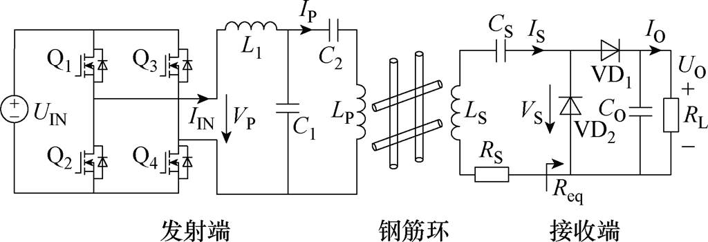
图3 系统电路拓扑
Fig.3 The topology of the system
将每个钢筋环都视作导体[21],则每个钢筋环都存在内阻RJ和自感LJ。轨道板中有两层钢筋网,由于另一层钢筋距离远,所以只考虑一层钢筋网的情况。接收线圈在钢筋网格中位置示意图如图4所示,组成钢筋环的每根钢筋内阻和自感均为RJ/4和LJ/4。发射线圈正对钢筋环J5、J6,可忽略横向距离远的钢筋影响,故分析时选用九宫格的钢筋网,用Ji(i=1, 2, 3,…, 9)表示,将钢筋环中感应电流IJ方向均取为顺时针方向。当钢筋上方发射线圈产生磁场时,钢筋回路可作为中继线圈,且每个钢筋回路和发射线圈之间都会有相应的互感,用Mi(i=1, 2, 3,…, 9)表示,如M5表示发射线圈与J5钢筋环之间的互感。
发射线圈与钢筋互感计算机构示意图如图5所示,Tx1和Tx2表示DD线圈的两个子线圈。在建立的参考坐标系中,h1为钢筋环的纵坐标;h2为发射线圈的纵坐标;l2为钢筋环内侧正方形边长的一半;l1为发射线圈内侧正方形边长的一半;钢筋环J5的中心O1与Z轴重叠;发射线圈Tx1和Tx2的中心O3和O4在YZ平面上;将发射线圈和钢筋环之间的高度差记为H,H=h2-h1,h1和h2分别为钢筋环和发射线圈到参考坐标系XOY平面的距离。
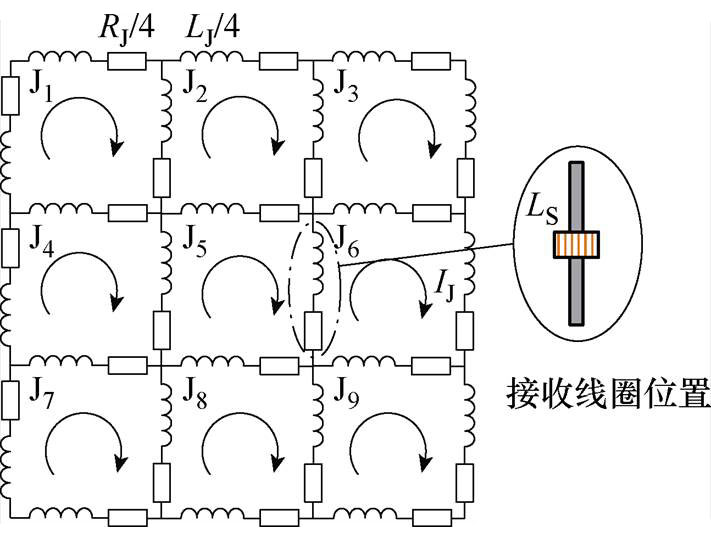
图4 接收线圈在钢筋网格中位置示意图
Fig.4 Diagram of the position of the receiving coil in the rebar array
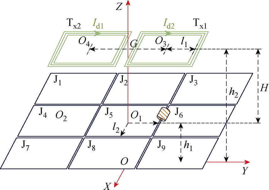
图5 发射线圈与钢筋互感计算机构示意图
Fig.5 Diagram of mutual inductance calculation between rebar array and transmit coil
单匝方形线圈之间的互感表达式[22]为
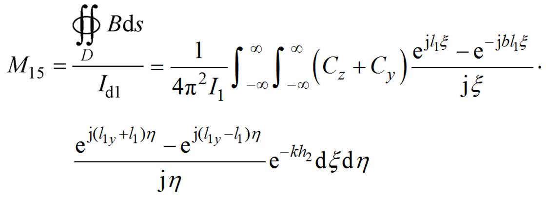 (1)
(1)
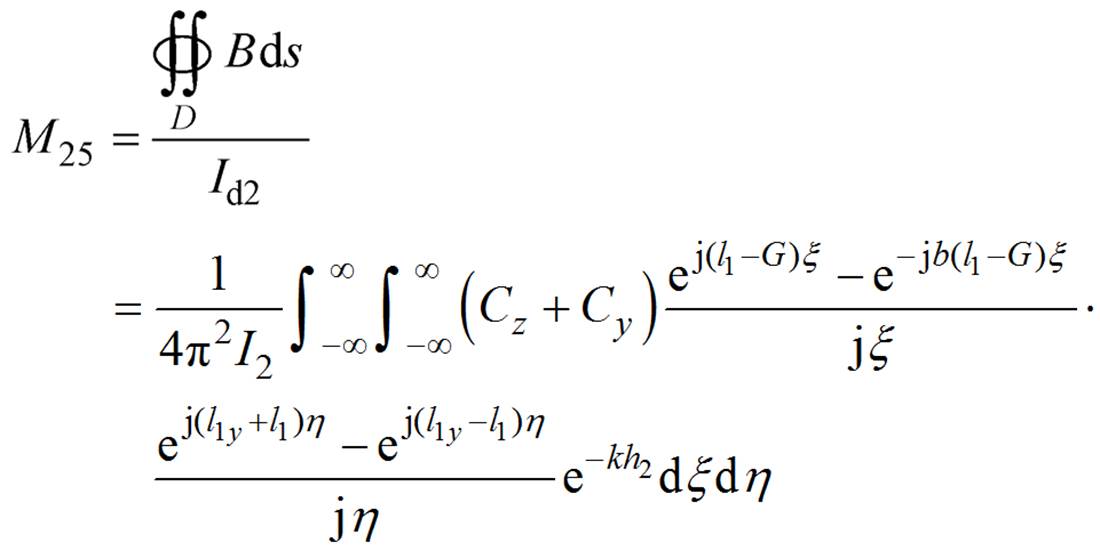 (2)
(2)
其中
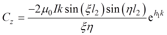
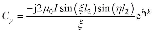
式中,Id1、Id2分别为Tx1、Tx2的电流;B为磁通密度;D为每个钢筋环围成面积;l1y为发射线圈在Y轴的偏移距离; 为空气中的磁导率。
多匝方形线圈之间的互感计算式为
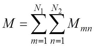 (3)
(3)
式中,N1为Ji的匝数;N2为发射线圈的匝数;m为Ji的第m匝;n为发射线圈的第n匝。
线圈、钢筋的尺寸大小取值见表1,取h1=0 mm,h2=150 mm,H=h2-h1=150 mm。改变G的大小,通过式(1)~式(3)计算可得到发射线圈Tx1和Tx2与钢筋环J5和J6之间的互感值的变化情况,移动过程中 变化曲线如图6所示,(
 为移动位置下对应的每个点,=1, 2, 3,…, j)为移动距离不同时相应发射线圈与接收线圈之间的互感,有
 (4)
(4)
式中, 和
和 分别为移动距离不同时发射线圈与钢筋环J5和J6之间的互感。
表1 理论计算尺寸参数
Tab.1 Dimensions of simulation
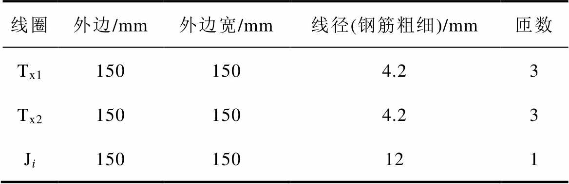
线圈外边/mm外边宽/mm线径(钢筋粗细)/mm匝数 Tx11501504.23 Tx21501504.23 Ji150150121
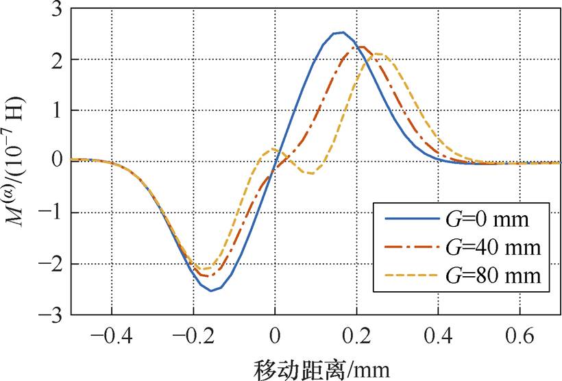
图6 移动过程中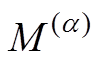 变化曲线
变化曲线
Fig.6 The curves of variation during movement
所述系统采用DD线圈作为发射线圈,如图5所示,当两个线圈之间的距离G固定时,两个线圈中电流Id1和Id2流过方向的不同会使产生的磁场方向不同,造成发射线圈与接收线圈之间的互感大小不同,Id1和Id2方向相同时简称同向线圈,Id1和Id2方向相反时简称异向线圈。
由式(4)结合表1中的参数,在G=60 mm时改变H的大小计算得到电流方向不同时产生的互感变化曲线,如图7所示。在G=60 mm,H变化时,图7a可得异向线圈更好,图7b可得同向线圈更好,则Id1和Id2的方向会影响大小,进而影响接收端获取能量的大小。
(a)H=150 mm,G=60 mm (b)H=300 mm,G=60 mm
图7 Id1和Id2方向变化下变化曲线
Fig.7 The curves of variation with different direction of Id1 and Id2
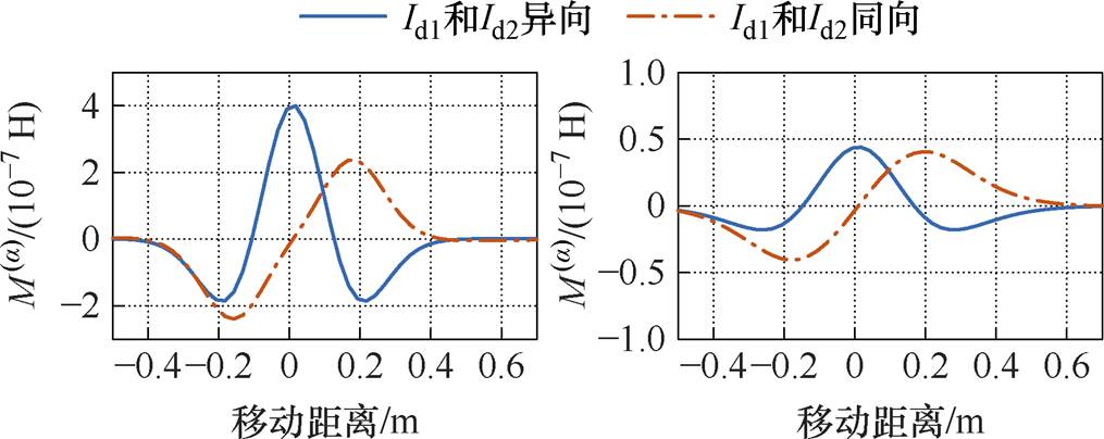
发射线圈中两个线圈之间距离G的不同也会影响两个线圈之间的磁场耦合,进而对发射线圈与接收线圈之间的互感大小产生影响。当G足够大时,两个线圈就可以看作是两个独立线圈,所讨论的G变化范围不会出现这种情况,其取值范围为0~120 mm。G变化下变化曲线如图8所示。
(a)H=300 mm,Id1和Id2异向 (b)H=300 mm,Id1和Id2同向
图8 G变化下变化曲线
Fig.8 The curves of variation with different G
如图8a和图8b所示,在H=300 mm时,G=0 mm时同向线圈产生互感更大,G=200 mm时异向线圈产生互感更大,则G的变化会影响的大小,进而影响接收端获取能量大小。
根据基尔霍夫电压定律,对系统(见图3)进行分析,可得
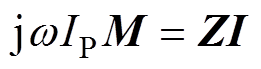 (5)
(5)
其中
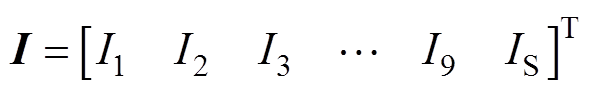
式中,w 为系统角频率; 为系统工作频率;Ii为流过每个钢筋回路相应的电流,如I1表示流过钢筋环J1的电流。
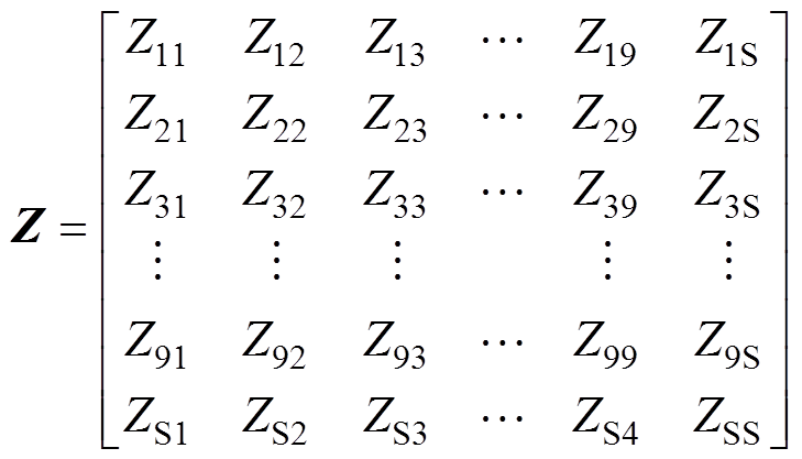
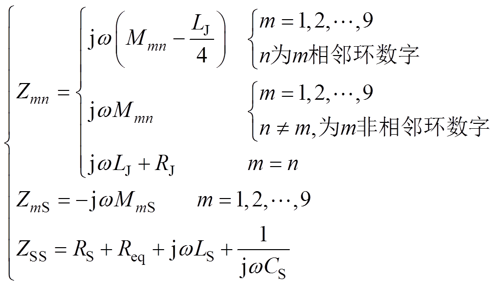 (6)
(6)
式中,Zmn(m≠n)为各钢筋环之间互感的感抗;Zmn(m=n)为钢筋环的阻抗和感抗之和;ZmS为各钢筋环与副边线圈之间互感的感抗;ZSS为副边LS、CS、Req构成回路的等效阻抗和感抗之和。
求解式(5),可得副边电流 为
为
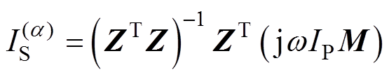 (7)
(7)
将 代入式(8)可得到输出功率
 为
为
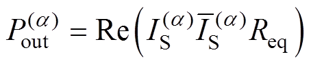
 (8)
(8)
其中
式中, 为取
为取 的实部;
的实部; 为的共轭。
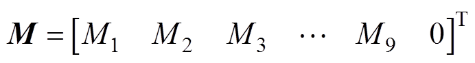
为的共轭。 可通过式(3)得到,且有M1= M7,M2=M8,M3=M9。
在整个移动过程中,副边线圈输出的等效功率 为
为
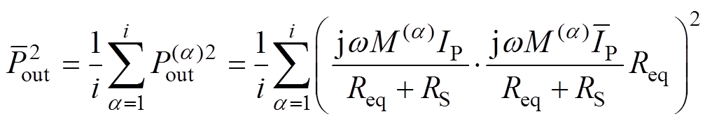
 (9)
(9)
 (10)
(10)
式中,Meq为发射线圈和接收线圈的等效互感; 为
为 的共轭。由式(9)可知,和Meq呈正相关,则Meq可以用于反映的大小。
对于不同的应用,检测车的限界不一样,可将H作为一个设计发射线圈的衡量依据,其取值范围为150~400 mm,通过对Id1和Id2的方向、线圈间距G的设计,使得接收线圈在目标高度H下所获取的能量最大,也就是使最大。
对比Id1和Id2同向和异向两种情况下,由式(10)计算得到G和H变化时Meq的变化数据绘制成两个曲面,如图9所示。
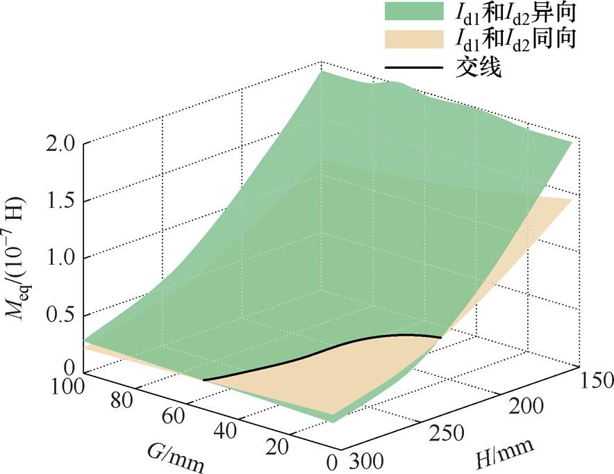
图9 G和H变化下Meq变化曲线
Fig.9 The curves of Meqvariation with different G and H
由图9可知,以H为变量,在约H>250 mm时,同向线圈在更大G的变化范围内产生的互感值更大,传能效果更好;在约H<220 mm时,异向线圈产生的互感值更大,使副边输出更大功率;以G为变量,在H从小到大变化时,有着相同的变化趋势,互感值更大的情况均是从采用同向线圈过渡到采用异向线圈。综上所述,当G越小(约<50 mm),H越大(约>225 mm)时,采用同向线圈得到的互感值更大;反之,则是采用异向线圈得到的互感值更大。
搭建如图10所示原理样机。各部分之间按照图3所示连接方式,输入采用恩智公司型号为N3412的直流电源给逆变器供电,控制发射线圈的恒流。采用艾德克斯电子公司型号为IT8818BS的电子负载,设定负载固定在50 W,整体的系统参数见表2。DD线圈实物如图10a所示,Id1和Id2的同向和异向通过改变左右两个线圈之间的连接方式改变。
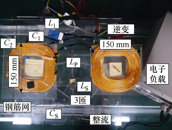
(a)系统装置
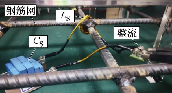
(b)接收装置
图10 实验装置
Fig.10 Experimental setup
在移动原边线圈过程中,选取的最大值 点和另一个较小值点的波形作比较。IR为流过钢筋环J5的电流。由于副边线圈与补偿电容呈串联谐振关系,因此整流桥的输入电压VS可以近似等效为感应电压的大小。如图11a和图11b所示,分别在H=150 mm和H=300 mm,Ip大小、Id1和Id2方向、G大小不变时,会随移动距离的变化而变化。
H=150 mm时,不同G、Id1和Id2方向下,在移动过程中计算值与实验值如图12所示,在H= 150 mm,改变G、Id1和Id2方向时,的计算值与实验值十分接近,验证了理论分析的正确性。图12a为G=0 mm,Id1和Id2同向的情况;图12b为G=20 mm,Id1和Id2异向的情况。
表2 系统参数
Tab.2 System parameters
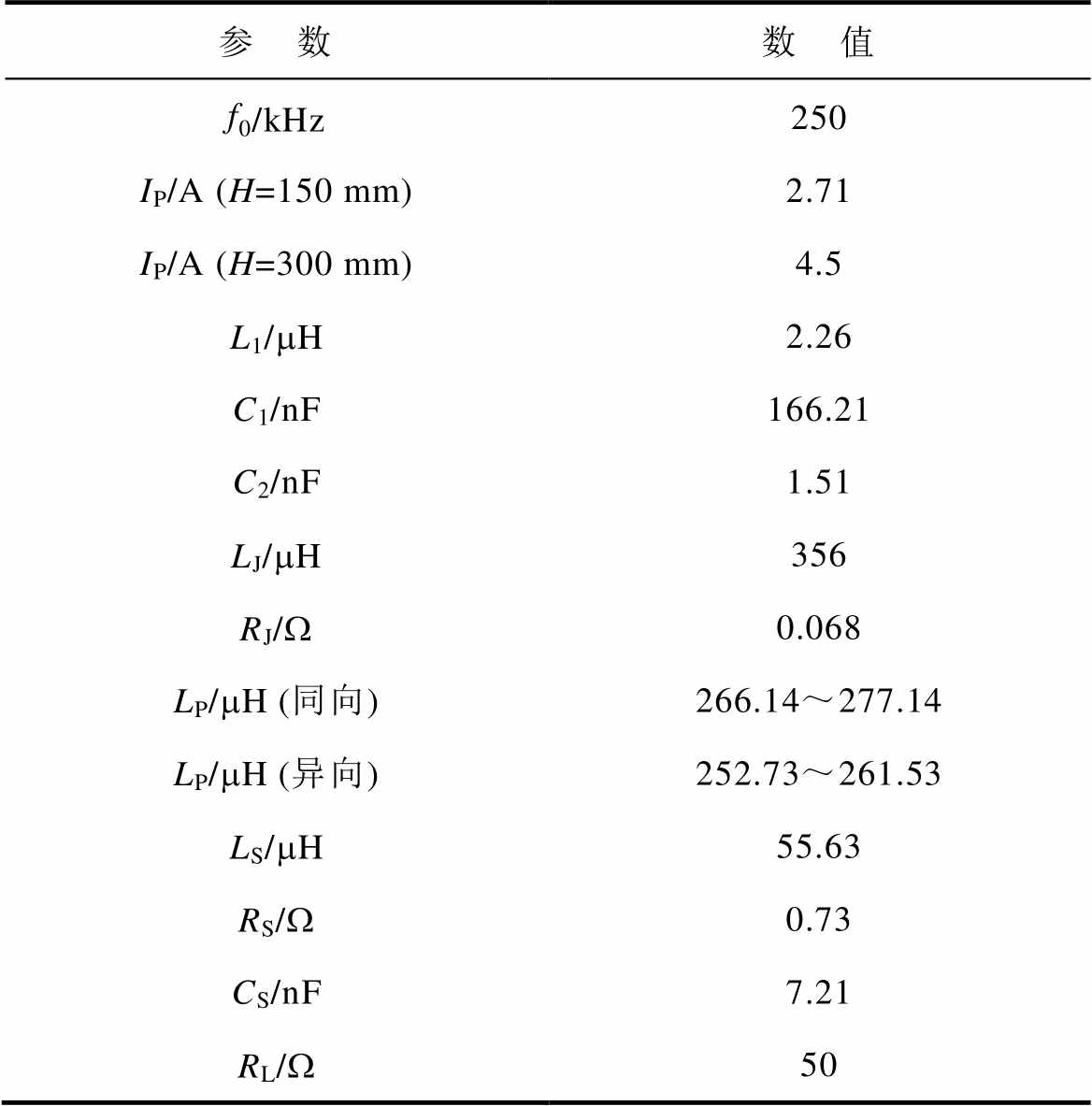
参 数数 值 f0/kHz250 IP/A (H=150 mm)2.71 IP/A (H=300 mm)4.5 L1/mH2.26 C1/nF166.21 C2/nF1.51 LJ/mH356 RJ/W0.068 LP/mH (同向)266.14~277.14 LP/mH (异向)252.73~261.53 LS/mH55.63 RS/W0.73 CS/nF7.21 RL/W50
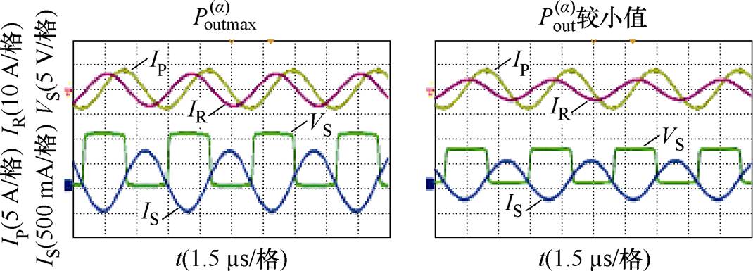
(a)H=150 mm,Id1和Id2同向,G=0 mm
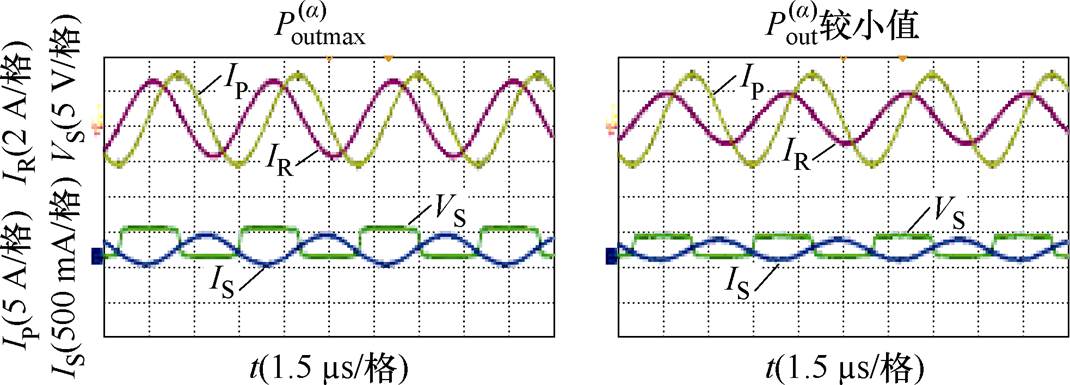
(b)H=300 mm,Id1和Id2同向,G=60 mm
图11 实验波形
Fig.11 Experimental waveforms
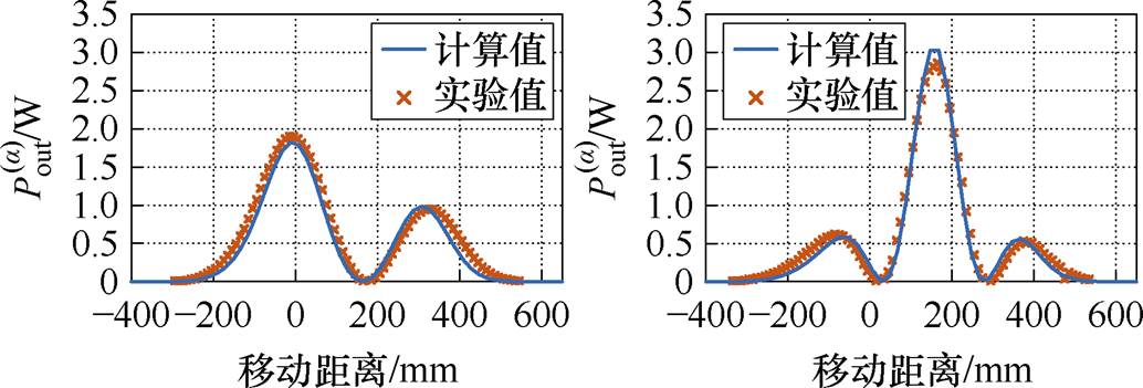
(a)G=0 mm,Id1和Id2同向 (b)G=20 mm,Id1和Id2异向
图12 H=150 mm时,不同G、Id1和Id2方向下, 在移动过程中计算值与实验值
Fig.12 Calculated and experimental value of with different G、direction of Id1 and Id2 under H=150 mm
在H=300 mm,改变G、Id1和Id2方向时, 的计算值与实验值如图13所示,由图13可见,计算值与实验值在变化趋势上基本一致,验证了理论分析的正确性。图13a为G= 60 mm,Id1和Id2同向的情况;图13b为G=100 mm,Id1和Id2异向的情况。
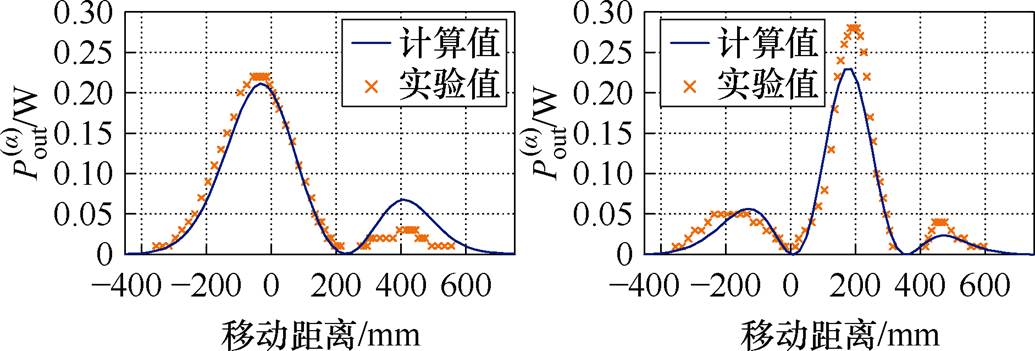
(a)G=60 mm,Id1和Id2同向 (b)G=100 mm,Id1和Id2异向
图13 H=300 mm时,不同G、Id1和Id2方向下,在移动过程中计算值与实验值
Fig.13 Calculated and experimental value of with different G、direction of Id1 and Id2 under H=300 mm
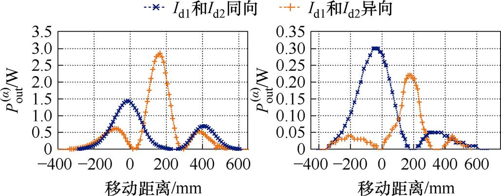
图14所示为在G=20 mm,改变H时,对比Id1和Id2同向、异向时的。图14a为H=150 mm,Id1和Id2同向、异向时的,可以得到此时选择Id1和Id2异向能让副边输出更大功率。图14b为H= 300 mm,Id1和Id2同向、异向时的,可以得到此时选择Id1和Id2同向能让副边输出更大功率。
(a)H=150 mm (b)H=300 mm
图14 G=20 mm时,不同H下,在移动过程中Id1和Id2不同方向的实验值
Fig.14 Experimental value of with different H、direction of Id1 and Id2 under G=20 mm
如图12~图14所示,在整个移动过程中,Id1和Id2无论异向还是同向,在移动距离为-400~600 mm时,副边才有输出功率。对于Id1和Id2同向/异向的情况,左右两个波峰不对称,这与接收线圈位置有关,如图4所示,分析时接收线圈未置于中间,在靠近边缘的地方,故导致接收到的能量不对称。
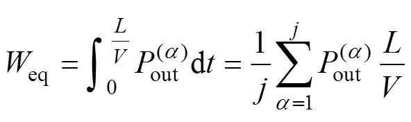 (11)
(11)
由式(11)可得,检测车以一定速度V行驶通过长度为L的距离后副边能获取能量Weq。若检测车以7 m/s(约25 km/h)的速度移动1 m,在H= 150 mm时,异向线圈获取能量 可达0.14 W×s,同向线圈获取能量仅有0.07 W×s,则优化线圈后选择异向线圈可将副边接收能量提升50%。
为了使预埋传感器在检测车通过时获取能量最大化以保证其长期稳定工作,本文通过动态无线供电系统在发射端与接收端高度差不同时的等效功率分析,对发射线圈电流方向、线圈间距进行参数优化,使接收端获得最大能量。此能量同时受到发射线圈电流方向和线圈间距的影响,在高度差小于220 mm时,采用异向线圈且线圈间距越大越好,间距在120 mm时最佳;在高度差大于225 mm时,采用同向线圈且线圈间距越小越好,间距在0 mm时最佳。优化后的异向线圈可获取0.14 W×s的能量,相较于优化前的同向线圈提升了50%,优化过程中实验数据与理论分析结果相吻合。考虑轨道交通车辆底部的铁磁材料后,系统互感变化趋势与本文中互感变化情况相同,可能需要对系统线圈参数进行调整,但文中所述方法依然适用,接下来可以对这一问题进行更详细的研究。
参考文献
[1] Abdulkarem M, Samsudin K, Rokhani F Z, et al. Wireless sensor network for structural health monitoring: a contemporary review of technologies, challenges, and future direction[J]. Structural Health Monitoring, 2020, 19(3): 693-735.
[2] 杨丽, 陈雪, 王子涵, 等. 基于激光诱导石墨烯的柔性超疏水温度传感器研究[J]. 电工技术学报, 2023, 38(增刊1): 257-266.
Yang Li, Chen Xue, Wang Zihan, et al. Research on flexible and superhydrophobic temperature sensor based on laser-induced graphene[J]. Transactions of China Electrotechnical Society, 2023, 38(S1): 257-266.
[3] Liu Zhaowei, Li Yong, Yang Huanyu, et al. An accurate model of magnetic energy harvester in the saturated region for harvesting maximum power: analysis, design, and experimental verification[J]. IEEE Transactions on Industrial Electronics, 2023, 70(1): 276-285.
[4] Bhuiyan R H, Islam M R, Caicedo J M, et al. A study of 13.5-MHz coupled-loop wireless power transfer under concrete and near metal[J]. IEEE Sensors Journal, 2018, 18(23): 9848-9856.
[5] 黄文聪, 饶天彪, 蒋煊焱, 等. 无线电能传输系统最大效率追踪及恒压输出复合控制方法[J]. 电工技术学报, 2024, 39(12): 3589-3601, 3615.
Huang Wencong, Rao Tianbiao, Jiang Xuanyan, et al. Maximum efficiency tracking and constant voltage output compound control method for wireless power transfer system[J]. Transactions of China Electro- technical Society, 2024, 39(12): 3589-3601, 3615.
[6] Chen Feng, Taylor N, Balieu R, et al. Dynamic application of the inductive power transfer (IPT) systems in an electrified road: dielectric power loss due to pavement materials[J]. Construction and Building Materials, 2017, 147: 9-16.
[7] 李江南, 李锐华, 胡波. 一种单发射多接收磁耦合式多频谐振无线电能传输方法[J]. 电气技术, 2023, 24(11): 1-9, 27.
Li Jiangnan, Li Ruihua, Hu Bo. A single-transmitter- multiple-receiver magnetic coupling multi-frequency resonant wireless power transfer method[J]. Electrical Engineering, 2023, 24(11): 1-9, 27.
[8] 陈阳, 杨斌, 彭云尔, 等. 感应式无线电能传输系统抗偏移技术研究综述[J]. 中国电机工程学报, 2023, 43(14): 5537-5556.
Chen Yang, Yang Bin, Peng Yuner, et al. Review of anti-misalignment technology in inductive wireless power transfer system[J]. Proceedings of the CSEE, 2023, 43(14): 5537-5556.
[9] 李争, 唐明磊, 解波, 等. 无线电能传输零电压开关角跟踪和动态电容补偿矩阵复合控制策略[J]. 电工技术学报, 2024, 39(12): 3602-3615.
Li Zheng, Tang Minglei, Xie Bo, et al. Composite control strategy of zero voltage switch angle tracking and dynamic capacitance compensation matrix for wireless power transfer[J]. Transactions of China Electrotechnical Society, 2024, 39(12): 3602-3615.
[10] 高鹏飞, 田晓盈, 杨志梁, 等. 非对称三线圈结构无线电能传输系统研究[J/OL]. 电气工程学报, 2023, http://kns.cnki.net/kcms/detail/10.1289.TM.20230531.2204.012.html.
Gao Pengfei, Tian Xiaoying, Yang Zhiying, et al. Research on the wireless power transfer system with asymmetric three coils structure[J]. Journal of Elec- trical Engineering, 2023, http://kns.cnki.net/kcms/ detail/10.1289.TM.20230531.2204.012.html.
[11] Ukita K, Kashiwagi T, Sakamoto Y, et al. Evaluation of a non-contact power supply system with a figure- of-eight coil for railway vehicles[C]//IEEE PELS Workshop on Emerging Technologies: Wireless Power, Daejeon, Korea (South), 2015: 1-6.
[12] Liu Yeran, Mai Ruikun, Liu Dengwei, et al. Effici- ency optimization for wireless dynamic charging system with overlapped DD coil arrays[J]. IEEE Transactions on Power Electronics, 2018, 33(4): 2832-2846.
[13] 冯天旭, 史可, 孙跃, 等. 基于互感识别及移相角优化的全方位无线电能传输系统靶向传能方法[J]. 电工技术学报, 2023, 38(24): 6581-6595.
Feng Tianxu, Shi Ke, Sun Yue, et al. Targeted power transfer method for omnidirectional wireless power transfer system based on mutual inductance identi- fication and phase-shift angle optimization[J]. Transactions of China Electrotechnical Society, 2023, 38(24): 6581-6595.
[14] 张鹏飞, 龚立娇, 马欣欣, 等. 具有可变增益恒压特性的双线圈无线电能传输系统补偿网络设计与分析[J]. 电工技术学报, 2024, 39(5): 1256-1269, 1283.
Zhang Pengfei, Gong Lijiao, Ma Xinxin, et al. Analysis and design of compensation network for two-coil wireless power transfer system with variable constant voltage gain characteristics[J]. Transactions of China Electrotechnical Society, 2024, 39(5): 1256- 1269, 1283.
[15] 李强, 李建贵, 王隆扬, 等. 基于Halbach效应的磁屏蔽无线输电耦合机构研究[J]. 电源学报, 2024, 22(2): 352-359.
Li Qiang, Li Jiangui, Wang Longyang, et al. Study on wireless power transmission coupling mechanism with magnetic shielding based on halbach effect[J]. Journal of Power Supply, 2024, 22(2): 352-359.
[16] Jafari H, Olowu T O, Mahmoudi M, et al. Optimal design of IPT bipolar power pad for roadway-powered EV charging systems[J]. IEEE Canadian Journal of Electrical and Computer Engineering, 2021, 44(3): 350-355.
[17] Xie Liguang, Shi Yi, Hou Y T, et al. Wireless power transfer and applications to sensor networks[J]. IEEE Wireless Communications, 2013, 20(4): 140-145.
[18] Jonah O, Georgakopoulos S V. Wireless power transfer in concrete via strongly coupled magnetic resonance[J]. IEEE Transactions on Antennas and Propagation, 2013, 61(3): 1378-1384.
[19] Qian Libo, Cui Kexue, Xia Huakang, et al. An inductive power transfer system for powering wireless sensor nodes in structural health monitoring applications[J]. IEEE Transactions on Microwave Theory and Techniques, 2022, 70(7): 3732-3740.
[20] Peng Yuner, Qi Wang, Chen Yang, et al. Wireless sensor power supply based on eddy currents for structural health monitoring[J]. IEEE Transactions on Industrial Electronics, 2024, 71(7): 7252-7261.
[21] Wang Zhihua, Markham A. Wirelessly powered embedded sensor nodes for internal structural health monitoring[J]. IEEE Transactions on Industrial Electronics, 2020, DOI: 10.1109/TIE.2020.3013536.
[22] 李中启, 李上游, 李晶, 等. 动态无线电能传输系统多接收线圈正反串联结构的互感计算与优化[J]. 电工技术学报, 2021, 36(24): 5153-5164.
Li Zhongqi, Li Shangyou, Li Jing, et al. Mutual inductance calculation and optimization of multi- receiver positive and negative series coil structure in dynamic wireless power transfer systems[J]. Transa- ctions of China Electrotechnical Society, 2021, 36(24): 5153-5164.
Abstract In rail transit fields, pre-embedded sensors are crucial for structural health monitoring due to their low power consumption (tens to hundreds of milliwatts) and small size. Pre-embedded in the concrete of the subgrade, they can obtain the corresponding key status information in real-time to warn of the subgrade deformation, slope instability, bridge, tunnel damage, and other hazards promptly. Continuous and reliable power supply is the basic premise of the normal operation of the pre-embedded sensors. However, the battery life span is limited, and the wired power supply can easily be damaged. In contrast, the wireless power supply method is easy to install and redeploy, reducing the interference of the construction machinery operation, which provides a new idea for the pre-embedded sensor wireless reliable power supply.
Using the inspection vehicle in its operation, the energy is radiated through the transmitting coil mounted on the bottom, and the receiving coil placed around the pre-embedded sensors along the railway line obtains the energy and stores it for the sensors. In the case of dynamic wireless power supply, the transmitter coils are mostly buried underground to supply power to the mobile devices carrying the receiver coils. However, these studies are mainly used for high-power electrical equipment, and the size of the receiving coil is comparable to that of the transmitting coil. At the same time, the shock characteristics of the transmitted energy during the movement of the inspection vehicle affect the smooth output, which is not applicable to the dynamic wireless power supply of pre-embedded sensors. The dynamic power supply is still in its infancy.
This paper proposes a method for optimizing the transmitting coil parameters of a dynamic wireless energy transmission system based on equivalent power analysis. The energy acquired at the receiver is maximized, providing an effective solution for the reliable power supply of the pre-embedded sensors. The rebar structure is modeled, and the mutual inductance of the transmitting and receiving coils is obtained. The equivalent power is obtained, and the influence of the DD coil current direction and spacing is analyzed.
Finally, an experimental prototype was built to verify the equivalent power calculation method of the proposed dynamic wireless power supply system. When the height difference is less than 220 mm, the DD coil with a different current direction and large coil spacing is good, and the spacing is optimal at 120 mm. When the height difference is more than 225 mm, the DD coil with the same current direction and small coil spacing is good, and the spacing is optimal at 0 mm. The optimized coil with a different current direction can obtain 0.14 W×s of energy, which is 50% higher than the pre-optimized coil with the same current direction. The experimental data during the optimization process agree with the theoretical analysis, which verifies the feasibility of the proposed method.
keywords:Pre-embedded sensors, dynamic wireless power transfer, parameter optimization, maximum equivalent power
DOI: 10.19595/j.cnki.1000-6753.tces.232124
中图分类号:TM724
国家自然科学基金项目-联合基金项目(U22A20222)、四川省自然科学基金创新研究群体项目(2023NSFSC1975和国家重点研发计划重点专项(2023YFB4302002)资助。
收稿日期 2023-12-21
改稿日期 2024-07-22
王 淇 女,2000年生,硕士研究生,研究方向为无线电能传输技术及其应用。E-mail: wangqi2022@my.swjtu.edu.cn
麦瑞坤 男,1980年生,教授,博士生导师,研究方向为无线电能传输技术在轨道交通中的应用。E-mail: mairk@swjtu.edu.cn(通信作者)
(编辑 崔文静)