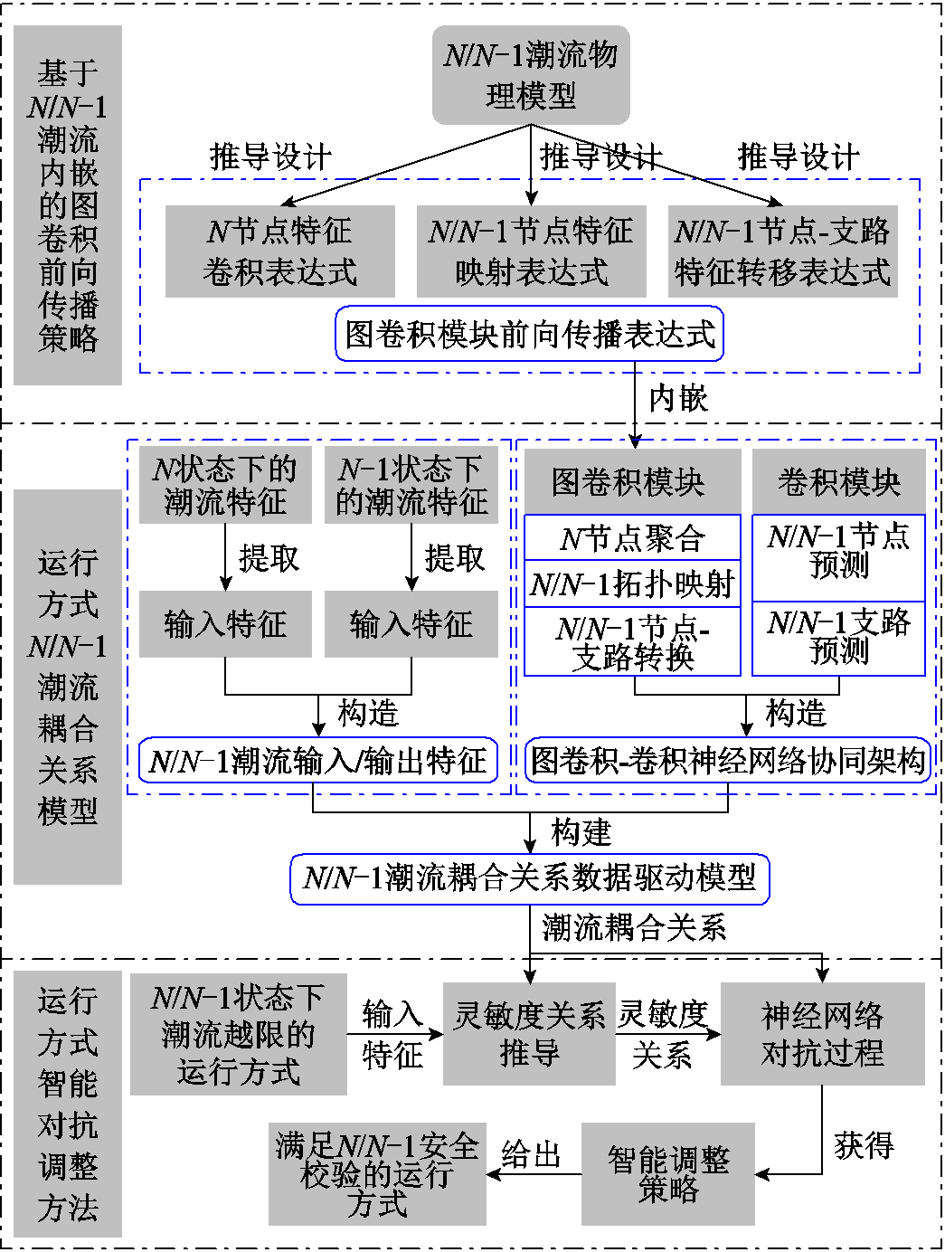
图1 基于N/N-1潮流内嵌图卷积神经网络的电网运行方式智能调整框架
Fig.1 Intelligent adjustment framework of operation mode based on N/N-1 power flow embedded GCNN
摘要 运行方式调整是确保电力系统安全稳定运行的关键措施之一,目前工业界仍以人工调整为主。但随着大量新能源接入和电力电子设备应用,电网规模和复杂程度不断增加,导致依靠人工经验以试凑法进行反复调整的人工调整方法面临效率低下、理论指导欠缺的问题。对此,该文提出了基于N/N-1潮流内嵌图卷积神经网络的电网运行方式智能调整方法。首先,以N/N-1潮流物理模型推导设计图卷积模块前向传播表达式,提出了基于N/N-1潮流内嵌的图卷积前向传播策略,高效地提取了电力系统复杂拓扑特征和潮流物理特征;其次,以电力系统N/N-1状态下潮流特征作为输入/输出特征,构建了基于多层图卷积和卷积神经网络模块协同的运行方式N/N-1潮流耦合关系模型,表征N/N-1状态下的数据驱动潮流耦合关系;然后,针对N/N-1状态下潮流越限的运行方式,提出了基于N/N-1潮流耦合关系的运行方式智能对抗调整方法,以获得运行方式精准调整策略,确保其满足静态N-1安全校验;最后,在IEEE 30节点和某实际大电网341节点系统上进行算例分析,结果验证了所提方法可智能调整N/N-1状态下潮流越限的运行方式至满足静态N-1校验。
关键词:运行方式调整 N-1安全校验 图卷积神经网络 潮流内嵌 对抗过程
运行方式调整是确保电力系统安全稳定运行的关键措施之一[1]。随着高比例可再生能源和高比例电力电子设备的“双高”趋势,电网规模和复杂程度不断增加,实际电网运行方式调整难度大。对此,国家能源局综合司发布《关于完善电力系统运行方式分析制度强化电力系统运行安全风险管控的通知》[2],突显对电力系统运行方式调整的迫切性。在现实中,N/N-1状态下潮流越限的运行方式可能导致设备过载、线路损坏、系统不稳定等安全风险[3-4]。因此精确制定运行方式调整策略,以消除其N/N-1状态下潮流越限(即满足N-1安全校验),具有至关重要的意义。
针对运行方式的调整,目前,工业界仍以人工调整为主。工作人员通过人工经验采用试凑法,针对N/N-1状态下潮流越限的运行方式进行反复调整,该方法具有较强的可解释性,但存在以下两方面问题:①依赖人工经验,难以形成规范、统一的理论指导规则;②需进行大量N/N-1状态潮流计算和反复调整运行方式,低效耗时[5]。因此,针对新型电力系统,亟须进一步研究具有规范理论指导且高效的运行方式调整方法。
针对运行方式的调整,目前学术界进行了深入研究,主要可分为直接优化法和数据驱动法。其中,直接优化法能通过优化算法求解优化模型,直接得到运行方式调整策略,相对于人工调整方法,具有明显的高效性优点。例如,有研究通过灵敏度法寻找调整节点,进而使用内点法求解运行方式优化模型,采取调整发电机节点出力、切负荷等措施,直接获得N状态下潮流越限的运行方式调整策略[6-10];还有学者利用基于群体智能理论(如改进粒子群算法[11]、遗传模拟退火粒子群算法[12]、改进鸟群算法[13]等)的优化算法求解电网优化调度模型,得到满足N状态下潮流约束的发电机节点出力、切负荷等优化调整策略。除了仅考虑N状态的运行方式调整外,还有研究人员建立了关于调整N-1状态下越限潮流的潮流优化模型,并使用内点法进行求解,可直接控制发电机出力和负荷参与N-1故障后的潮流调整[14-18]。由于考虑所有N-1约束条件,上述潮流优化模型规模庞大,求解效率低下,文献[19]基于深度学习算法智能筛选起作用的N-1安全约束,进一步构建潮流优化模型,快速求解最优潮流,提升了求解效率。上述方法的求解算法都为迭代求解法,为了进一步更高效地解决运行方式的调整问题,研究人员开始将数据驱动方法应用于该领域[20-21]。已有学者用全连接神经网络(Fully Connected Neural Network, FCNN)[22-23]、卷积神经网络(Convolutional Neural Networks, CNN)[24]、贝叶斯神经网络(Bayesian network)[25]、深度Q网络(Deep Q-Network, DQN)[26-29]等数据驱动方法直接表征N状态下潮流耦合关系,进一步得出考虑N状态下的运行方式调整方案。以上数据驱动方法虽能有效地提取潮流非线性特征,但对拓扑特征的提取能力有限,文献[30]采用嵌入潮流物理模型的图卷积神经网络(Graph Convolution Neural Network, GCNN)进行潮流优化,不仅能有效地提取拓扑特征,而且能给出N状态下潮流越限运行方式的调整策略。但以上数据驱动方法均缺乏对N-1状态下潮流越限运行方式调整的研究。更重要的是,直接优化法和数据驱动法虽然能够获得运行方式的最终调整策略,但无法给出调整前后运行方式的过渡过程和内在联系,导致工作人员难以对运行方式调整问题进行解释和剖析,影响决策效率。因此,还需要进一步研究以下两个问题,才能深入分析调整前后运行方式的过渡过程和内在联系:①有效表征N/N-1状态下的潮流耦合关系;②精准解析调整前后运行方式之间的调整流程。
针对上述问题,本文提出了基于N/N-1潮流内嵌图卷积神经网络的电网运行方式智能调整方法,其结构如图1所示。
该方法通过提出图卷积前向传播策略,构建运行方式N/N-1潮流耦合关系,进一步基于对抗过程[31-32]设计运行方式调整策略,实现对不满足静态N-1安全校验的运行方式高效智能调整。本文主要贡献有如下三点:
1)提出了基于N/N-1潮流内嵌的图卷积前向传播策略,以N/N-1潮流物理模型推导了设计图卷积模块前向传播表达式,实现对电力系统N/N-1状态下的节点特征和支路特征的有效提取。
图1 基于N/N-1潮流内嵌图卷积神经网络的电网运行方式智能调整框架
Fig.1 Intelligent adjustment framework of operation mode based on N/N-1 power flow embedded GCNN
2)以电力系统N/N-1状态下潮流特征作为输入/输出特征,构建了基于多层图卷积和卷积神经网络模块协同的运行方式N/N-1潮流耦合关系模型,精确表征N/N-1状态下的数据驱动潮流耦合关系。
3)提出了基于N/N-1潮流耦合关系的运行方式智能对抗调整方法,精准解析调整前后运行方式的调整流程,实现在N/N-1状态下潮流越限的运行方式调整至满足N-1安全校验。
针对神经网络对拓扑特征提取能力有限的问题,本节提出基于N/N-1潮流内嵌的图卷积前向传播策略,为第2节构建N/N-1潮流耦合关系模型提供图卷积神经网络模块。本节所提图卷积前向传播策略以N/N-1潮流模型引导图节点进行邻域聚集和特征更新,不仅能有效地提取N/N-1状态下的潮流拓扑特征、节点电压特征和支路功率特征,而且遵循了图节点特征所满足的物理规则和意义,具体介绍如下。
GCNN是一种基于图结构的神经网络,其中包含节点集合 和支路集合
和支路集合 的图结构表示为
 ,n为节点数,b为支路数。图的邻接矩阵
 存储了节点之间的邻接关系,节点的输入特征向量矩阵为
 ,
, 为输入特征向量的维度,则图卷积层前向传播公式可表示为
 (1)
(1)
式中, 为图卷积层的输出矩阵;
 为可训练的参数矩阵;
 为邻域聚集函数;
 为激活函数。
前向传播式(1)中的 表示邻域聚集过程,该过程能整合邻接节点信息,提取拓扑网络特征,一般邻域聚集过程较为简单,如
 。这对于结构复杂、网络变换的新型电力系统来说,难以有效提取其拓扑特征和物理特征[30]。因此为了图卷积层更好地嵌入电力系统图结构,精准提取拓扑网络特征,本文将设计具有相邻节点关系、隐含电力系统物理规则的前向传播公式,使图卷积层在邻域聚集过程中具有物理规则的引导。
本小节提出的基于N/N-1潮流内嵌的图卷积前向传播模块框架如图2所示。
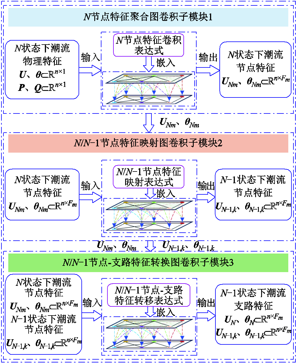
图2 基于N/N-1潮流内嵌的图卷积前向传播模块框架
Fig.2 Graph convolution forward propagation module framework based on N/N-1 power flow embedding
针对图卷积子模块1,其输入特征包含N状态下潮流节点电压幅值特征向量 、电压相位特征向量
 、注入有功功率特征向量
 和注入无功功率特征向量
 ,得到图卷积子模块1的输入特征X,具体表示为
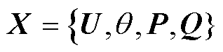 (2)
(2)
式中, ,
, 为第
为第 个节点的电压幅值;
 ;
; ;
;
 ;
; 。
。
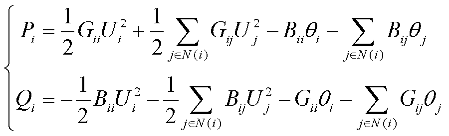
图卷积子模块1中嵌入N状态潮流物理模型的前向传播表达式可基于文献[33]推导,其从如式(3)所示的N状态下潮流方程[34]开始,利用高斯-赛德尔迭代法推导得到N状态下第l层图卷积层的邻域聚集特征 和
和 ,如式(4)所示。
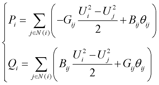 (3)
(3)
 (4)
(4)
式中, 、
、 分别为第i个节点的注入有功功率和注入无功功率;
 、
、 分别为电导矩阵G和电纳矩阵B中第i行与第j列的元素;
 为从节点i到节点j的电压相位差;
 为节点i的邻接集合;l为图卷积层数,l=1,2,…,m,m为图卷积子模块1中图卷积层总层数;单位矩阵
 ,
, 为第l层输出特征的维度;
 ,
, ,分别为第l层图卷积层输出的N状态下电压幅值特征和相位特征。
进一步根据图卷积计算规则,将和分别乘以第l层图卷积层的卷积核 和
和 (通过训练获取),进行特征更新,得到如式(5)所示的图卷积子模块1的前向传播表达式。
 (5)
(5)
式中, 为激活函数,选用ReLU(Rectified Linear Unit),其可在图卷积子模块1前向传播中引入非线性因素,使得神经网络能够逼近任何复杂的非线性函数,并有助于过滤掉不重要的特征。
当l=1时,、 为图卷积模块1的输入特征,即
 、
、 。进一步可基于式(5),从第1层到第m层逐层前向传播,得到图卷积模块1的输出特征
 、
、 ,其可用
,其可用 表示为
表示为
 (6)
(6)
针对图卷积子模块2,其输入特征矩阵是图卷积子模块1输出的特征矩阵,通过子模块2的图卷积操作(具体在1.3小节介绍),其输出特征包含:K个N-1状态下的节点电压幅值特征矩阵 和相位特征矩阵
 ,其中
,其中 ,其可用
,其可用 表示为
表示为
 (7)
(7)
式中,k=1,2,…,K,K为所考虑N-1的状态数。
针对图卷积子模块3,其输入特征是图卷积子模块1输出的特征矩阵和图卷积子模块2输出的特征矩阵,通过子模块3的图卷积操作(具体在1.3小节介绍),其输出特征包含:N状态下的支路有功功率特征矩阵 、无功功率特征矩阵
 以及K个N-1状态下的支路有功功率特征矩阵
 、无功功率特征矩阵
 ,其中,
,其中,
 ,可用
,可用 表示为
表示为
 (8)
(8)
本小节所提基于N/N-1潮流内嵌的图卷积前向传播模块框架介绍了每个子模块输入和输出特征、三者之间的关系,以及子模块1的前向传播表达式,但要实现N/N-1耦合关系的表征,还需推导设计子模块2和子模块3的前向传播表达式,包括N/N-1节点特征映射表达式和N/N-1节点-支路特征转移表达式,以有效提取N状态和N-1状态下的节点电压特征和支路功率特征,其具体推导过程将在1.3小节进行详细介绍。
本小节将基于式(3)所示的N状态下潮流方程推导设计图卷积子模块2的前向传播表达式。将式(3)中的展开成 和
和 ,可使潮流方程转换为
 (9)
(9)
将 、
、 、、、
、、、 、
、 分别构造成其对应的向量或矩阵形式,进一步将式(9)转换为
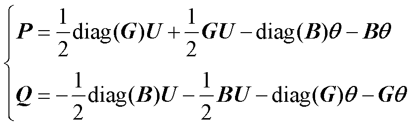 (10)
(10)
式中, 为
为 的对角矩阵。
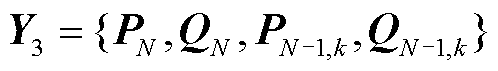
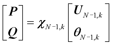
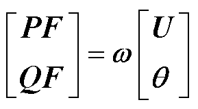
进一步对式(10)进行矩阵合并,整理成式(11),即得到N状态下节点注入功率P、Q与电压U、 之间的关系,其中
 为N状态下的电压-功率转换系数矩阵。
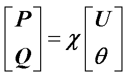 (11)
(11)
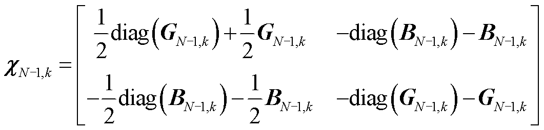
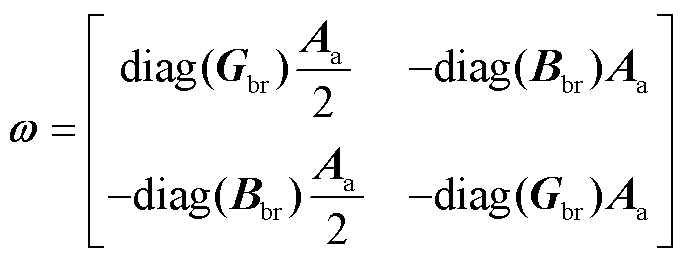
其中
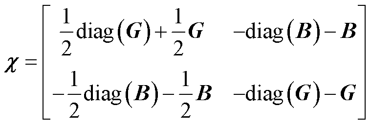 (12)
(12)
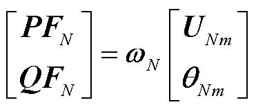
当电力系统断开第k条支路时,即第k个N-1状态下,其中新能源出力、传统发电机出力和负荷构成的节点注入功率P、Q不变,因此根据式(11)可得N-1状态下节点注入功率P、Q与电压 、之间的关系,如式(13)所示,其中
 为N-1状态下的电压-功率转换系数矩阵,具体表示为
 (13)
(13)
 (14)
(14)
式中, 表示第k条支路断开时与N状态相对应的
 。
。
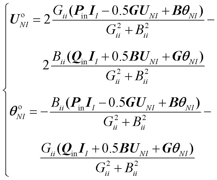
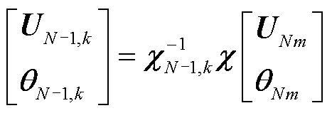
可知,式(11)和式(13)可连等,去除等式中的注入功率项,再将求逆后同时左乘等式两侧,最终得到如式(15)所示的N/N-1节点特征映射表达式。
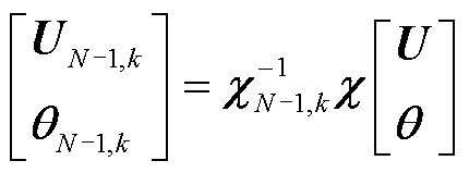 (15)
(15)
依托式(15)可设计出以 为卷积核的图卷积子模块2前向传播公式,如式(16)所示,其输入特征为,输出特征为。
 (16)
(16)
接下来基于式(17)所示的支路功率方程,对本小节提出的图卷积子模块3前向传播表达式进行推导设计。
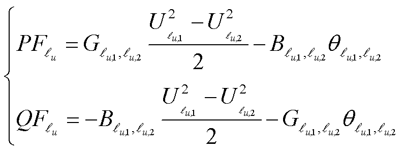 (17)
(17)
式中, 为支路,
为支路, ,u=1,2,…,b;
 、
、 分别为支路的有功功率、无功功率;
 和
和 分别为支路的首节点和末节点。
首先,建立支路-节点关联矩阵 ,其中
,其中 的每个元素表示节点i与支路
 间的关联关系,具体定义为
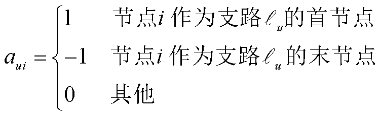 (18)
(18)
其次,可将、、 、
、 、
、 、
、 、
、 分别构造成向量形式,进一步利用支路-节点关联矩阵,将式(17)转换为
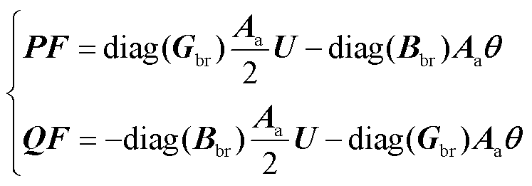 (19)
(19)
式中, ;
; ;
; ;
; 。
。
进一步对式(19)进行矩阵合并,可得节点-支路特征转移表达式为
 (20)
(20)
 (21)
(21)
依托式(20)可得N状态下的N节点-支路特征转移表达式以及N-1状态下的N-1节点-支路特征转移表达式,分别如式(22)、式(23)所示。
 (22)
(22)
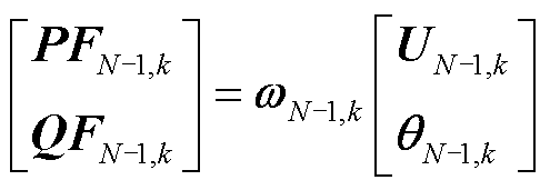 (23)
(23)
式中, 、
、 分别为N状态和第k个N-1状态下对应的
 。
。
以式(22)、式(23)作为图卷积子模块3前向传播公式,其中、为卷积核,输入特征为和,基于该前向传播公式,可得输出特征为 。
。
通过以上图卷积子模块的前向传播,神经网络能有效提取到电力系统N/N-1状态下的高维节点特征、和高维支路特征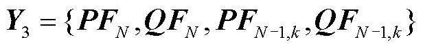 。
。
针对现有数据驱动方法缺乏表征N/N-1状态下的潮流耦合关系的问题,以第1节推导设计的图卷积前向传播策略为基础,本节首先设计多层图卷积和卷积模块协同的神经网络架构,进一步构建运行方式N/N-1潮流耦合关系数据驱动模型,为第3节的运行方式智能对抗调整方法提供模型基础。
根据每个子模块实现的不同作用,本节设计的多层图卷积和卷积模块协同的神经网络架构如图3所示,该架构包含:N节点特征聚合图卷积子模块1、N/N-1节点特征映射图卷积子模块2、N/N-1节点-支路特征转换图卷积子模块3、N/N-1节点特征预测卷积子模块1和N/N-1支路特征预测卷积子模块2,其中图卷积子模块的前向传播已在第1节提出,接下来将介绍卷积子模块1和卷积子模块2的前向传播表达式以及神经网络训练过程。
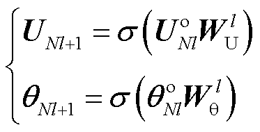
针对卷积子模块1,其作用是预测N状态和K个N-1状态下的节点电压特征,输入特征是图卷积子模块1输出的特征矩阵和图卷积子模块2输出的特征矩阵,卷积前向传播公式为
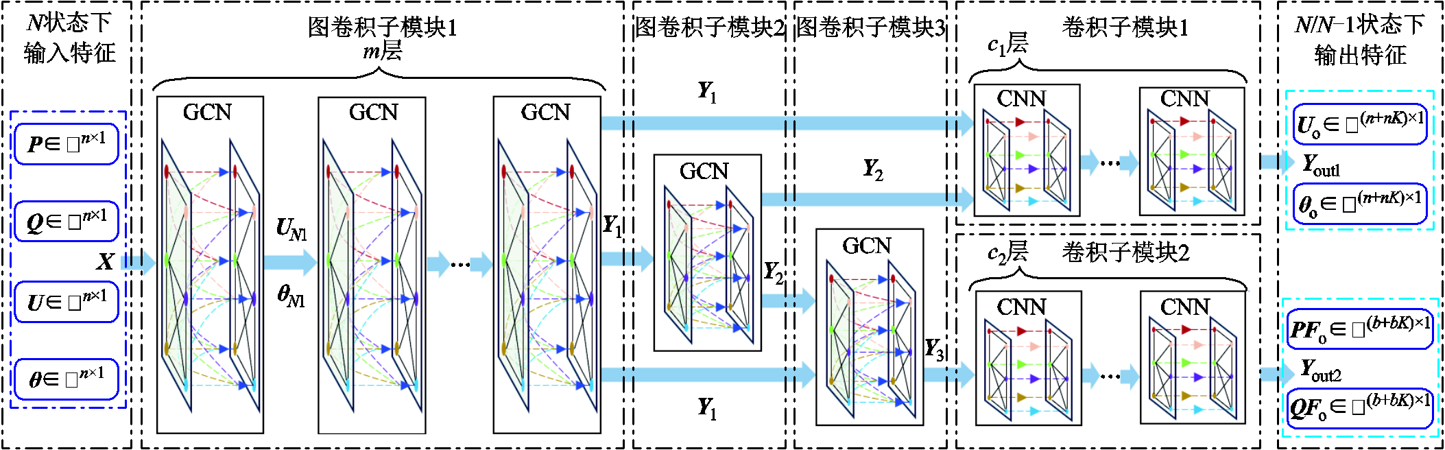
图3 多层图卷积和卷积模块协同的神经网络架构
Fig.3 Neural network architecture based on multi-layer graph convolution and convolution module collaboration
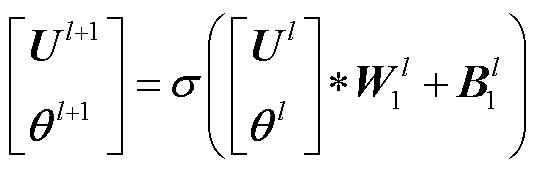 (24)
(24)
式中, ,
, 为卷积子模块1中卷积层总层数;
 、
、 分别为第l层卷积层输入的电压幅值特征和相位特征;
 、
、 分别为卷积层第l层的卷积核和偏置,需训练获取。当l=1时,、
 ,
, ,
, ;当
;当 时,
时, ,,
,, 为第l层的卷积核通道数。
当l=1时, ,
, ,k=1,2,…,K,通过前向传播公式(24)从第1层到第层逐层前向传播,最终可得输出特征:N状态下的节点电压幅值特征向量
 、相位特征向量
 ,以及K个N-1状态下的节点电压幅值特征向量
 、相位特征向量
 ,记电压幅值输出特征
 ,电压相位输出特征
 。
。
针对卷积子模块2,其作用是预测N状态和K个N-1状态下的支路功率特征,其输入特征是图卷积子模块3输出的特征矩阵
 ,其卷积前向传播公式为
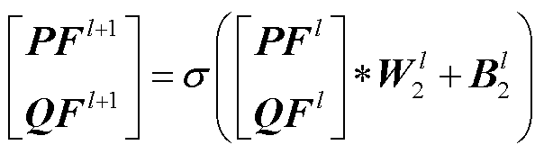 (25)
(25)
式中, ,
, 为卷积子模块2中卷积层总层数;
 、
、 分别为第l层卷积层输入的支路有功功率特征和支路无功功率特征;
 、
、 分别为卷积层第l层的卷积核和偏置,需通过训练获取。当l=1时,
 、
、 ,
, ,
, ,
, 为第l层的卷积核通道数;当
 时,
时, ,。
,。
当l=1时, ,
,
 ,k=1,2,…,K,依据前向传播公式(25),从第1层到第层逐层前向传播,最终可得输出特征:N状态下的支路有功功率特征向量
 、支路无功功率特征向量
 ,以及N-1状态下的支路有功功率特征向量
 、支路无功功率特征向量
 ,记支路有功功率输出特征
 ,支路无功功率输出特征
 。
。
值得注意的是,本文所提基于N/N-1潮流内嵌图卷积前向传播表达式,其核心目的在于引导神经网络遵循电力系统固有潮流物理规律进行信息的有效传递与处理。为了进一步确保模型能精准表征N/N-1状态下的潮流耦合关系,有必要依赖神经网络的自学习能力来动态调整和优化其内部的可训练参数集 ,即神经网络的训练。通过大量输入特征为
 、输出特征为
 的训练样本,采用梯度下降学习算法[35]对该神经网络进行训练,以高精度表征X与
 之间的高维耦合关系,具体内容如下。
为了评估模型预测值与真实值 之间的误差,使用均方误差为损失函数,损失值L计算公式为
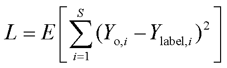 (26)
(26)
式中,E为期望; 和
和 分别为第i个预测值和真实值;S为预测值总数。
可训练参数集 是神经网络的核心组成部分,它们通过不断优化来使模型更好地学习数据模式、最小化损失函数,并提升预测性能和泛化能力。可训练参数需根据神经网络的损失值L不断进行更新,本文参数的更新基于梯度下降算法,用反向传播计算出的梯度来调整模型的参数,如式(27)所示。
 (27)
(27)
式中, 为学习率;
为学习率; 为损失值L对参数的偏导。
将式(26)代入式(27),基于链式法则可得到最终的可训练参数更新公式为
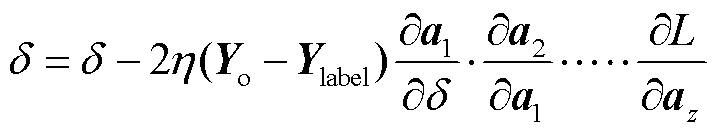 (28)
(28)
式中, 为神经网络第i层的激活函数输出;
 为损失函数对神经网络最后一层的激活函数输出的偏导数,
 为最后一层到第一层的链式法则应用的结果。
经过式(28)的参数更新,逐步优化神经网络,确定可训练参数的值,并使用早停法,防止模型过拟合,最终可得到运行方式N/N-1潮流耦合关系模型f。该模型可由N状态下的输入特征向量直接映射得到N/N-1状态下的输出特征向量,如式(29)所示。
 (29)
(29)
针对现有运行方式调整方法缺乏对调整前后运行方式之间调整流程的解析,本小节提出了基于N/N-1潮流耦合关系的运行方式智能对抗调整方法。以第2节的运行方式N/N-1潮流耦合关系为基础,推导出N/N-1状态下潮流越限量对输入特征的对抗过程公式;进一步提出基于对抗过程的运行方式智能可解释性调整方法,实现对运行方式的智能调整以及调整前后运行方式之间调整流程的解析。
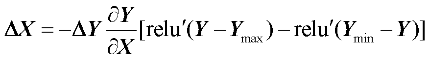
本小节基于N/N-1潮流耦合关系,推导N/N-1状态下潮流越限量对输入特征的对抗过程公式。本文考虑电压越限与支路有功功率越限情况,首先通过式(29)计算得到节点电压幅值输出向量 和支路有功功率输出向量
 ,记
,记 ,进一步根据对应输出特征的上限向量
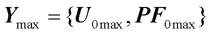 和下限向量
和下限向量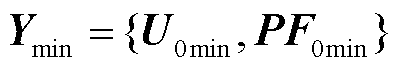 ,通过式(30)可计算出输出越限向量
 。
。
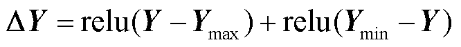 (30)
(30)
式中, 为ReLU函数,将负数映射为零,正数保持不变。
当输出越限向量 时,当前运行方式不满足静态N-1安全校验,则对运行方式输入特征X中的发电机节点注入有功功率、发电机节点注入无功功率、负荷、电压等逐步进行调整,直至输出越限向量
 ,为获取其中的调整策略,本文以
 为优化目标函数,并引入对抗过程[36]的思想来实现,具体过程如下。
首先,在运行方式存在电压越限或支路有功功率越限情况下,即时,计算出N/N-1状态下优化目标J对输入特征X的偏导 ,即
,即
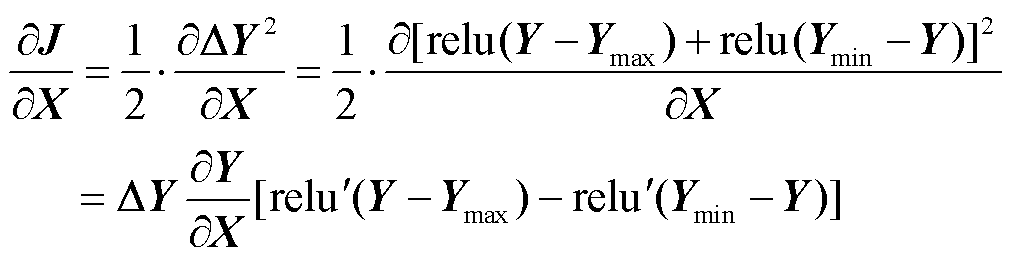 (31)
(31)
式中, 为Y对X的偏导;
 为激活函数的导函数。
其次,通过最速下降法可得到N/N-1状态下输出越限向量 对输入特征X的对抗过程公式,即
 (32)
(32)
式中, 为每步获取的输入调整策略向量。按照不断更新输入特征X,便可找到J的最小值。
根据第1节所提图卷积前向传播策略、第2节所提运行方式N/N-1潮流耦合关系模型,以及3.1小节所提的对抗过程思想,即可构建基于N/N-1潮流耦合关系的运行方式智能对抗调整方法,该方法流程如图4所示,具体步骤如下。
1)构建运行方式N/N-1潮流耦合关系模型f。首先,收集运行方式对应的N/N-1状态下潮流训练样本;其次,搭建如图3所示多层图卷积和卷积模块协同的神经网络架构;最后,基于式(28)所示的梯度下降训练算法训练得到运行方式N/N-1潮流耦合关系模型f。
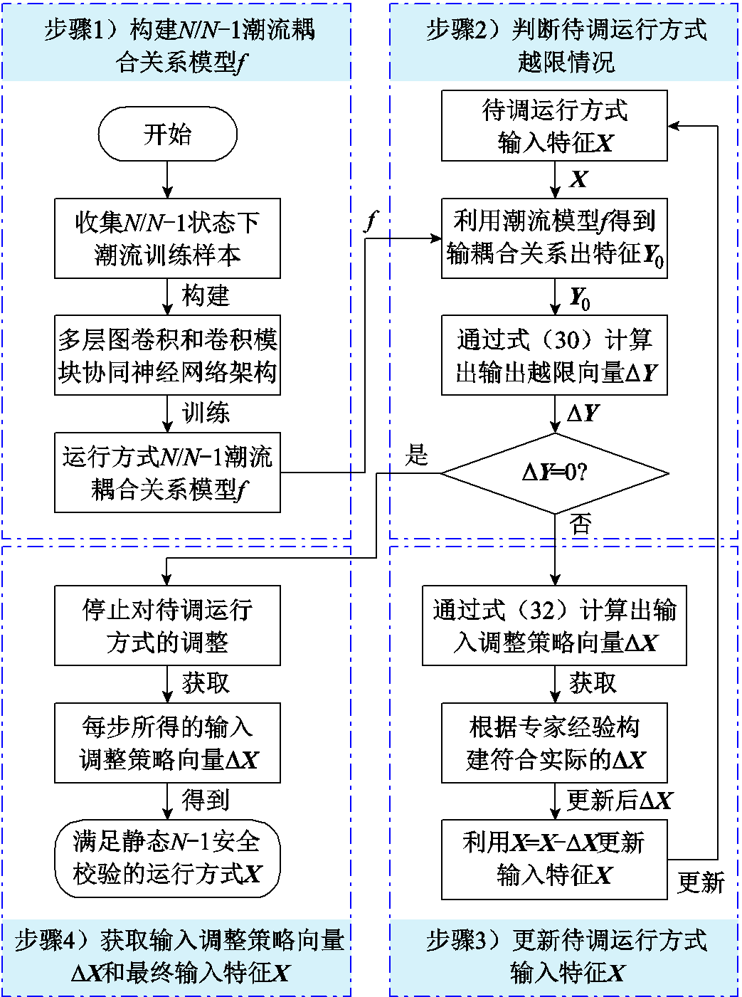
图4 运行方式调整策略智能生成方法流程
Fig.4 Operation mode adjustment flowchart of the intelligent generation method of policy
2)判断待调运行方式越限情况。首先,基于运行方式N/N-1潮流耦合关系模型f和待调运行方式输入特征X,得到输出特征 ;其次,通过公式(30)计算出输出越限向量;最后,判断是否为0,若
 ,则表示待调运行方式不越限,跳转至步骤4),否则,表示待调运行方式存在越限情况(即违背了静态N-1安全校验),需继续执行步骤3)。
3)基于对抗过程公式更新待调运行方式输入特征X。首先,利用式(31)计算N/N-1状态下优化目标J对输入特征X的偏导 ;其次,利用对抗过程式(32)得到输入调整策略向量,根据专家经验,选取中数值较大的作为关键调整对象,其余非关键调整对象都置零,且当关键调整对象的调整量超过对应发电机最大出力时,调整量取发电机对应限制值,从而获取到符合实际的输入调整策略向量;最后,通过
 更新待调运行方式输入特征X,并跳转至步骤2)。
4)首先,停止待调运行方式的调整;其次,获取每步所得的输入调整策略向量 ,以精准解析调整前后运行方式之间的调整流程;最后,得到最终输入特征X,即为调整后满足静态N-1安全校验的运行方式。
为验证本文所提方法对于调整存在N/N-1状态下潮流越限运行方式的有效性,在IEEE 30节点系统和某实际大电网341节点系统上进行算例分析。
针对不同规模的电力系统,多层图卷积和卷积模块协同的神经网络架构中图卷积子模块1、卷积子模块1和卷积子模块2的图卷积/卷积层数存在差异,本文对不同规模电力系统构建的神经网络架构设置见表1。
表1 不同规模电力系统构建的神经网络架构设置
Tab.1 Neural network architecture setting for power system construction of different scale
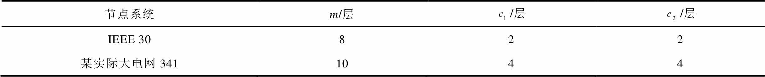
节点系统m/层/层/层 IEEE 30822 某实际大电网3411044
其中选择ReLU作为激活函数,设置10 000个训练样本和1 000个测试样本,每个样本的输出特征考虑11个状态,即K=10。
使用本文所提方法能有效调整运行方式的前提是运行方式N/N-1潮流耦合关系模型f预测效果好,能高精度表征N/N-1状态下的潮流耦合关系。为了验证这一点,在IEEE 30节点系统中,利用相同训练样本和梯度下降算法训练以下四种对比方法M0~M3构建的模型。
M0:本文所提基于多层图卷积和卷积神经网络模块协同的运行方式N/N-1潮流耦合关系模型。
M1[32]:基于全连接神经网络的潮流耦合关系模型(将M0中神经网络替换成全连接神经网络)。
M2:基于卷积神经网络的潮流耦合关系模型(将M0中神经网络替换成卷积神经网络)。
M3:基于图卷积神经网络的潮流耦合关系模型(将M0中神经网络替换成图卷积神经网络)。
其中精度p由概率准确性来衡量,如式(33)所示,反映了预测误差小于阈值的概率,并设置电压标幺值阈值 、相位阈值
、相位阈值 、支路有功功率阈值
 和支路无功功率阈值
 。
。
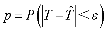 (33)
(33)
式中,T和 分别为预测值和真实值;
 为阈值;P为发生的概率。
首先,在1 000次迭代训练过程中统计了M0~M3的测试集平均精度变化情况,如图5所示。从图中可以看出,所有模型的精度都随着epoch的增加而提高,但M0在整个训练过程中较其他模型表现出了较好的稳定性和较高的精度。
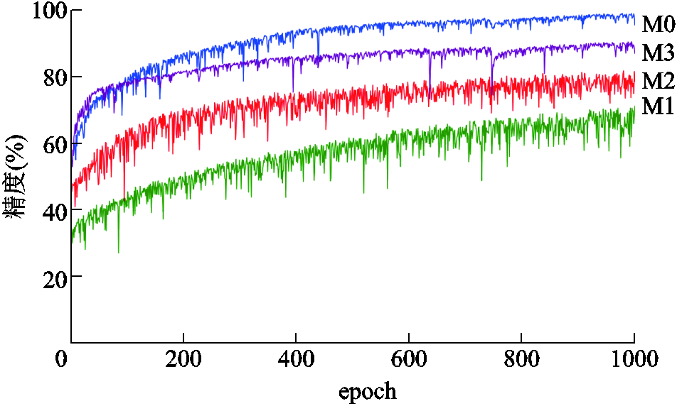
图5 M0~M3在训练过程中的精度变化情况
Fig.5 Accuracy changes of M0~M3 during the training process
通过训练好的模型对测试集进行预测,最终得到的运行方式N/N-1潮流耦合关系模型精度对比见表2。
表2 运行方式N/N-1潮流耦合关系模型精度对比
Tab.2 Accuracy comparison table of operation mode N/N-1 power flow coupling relationship model (%)
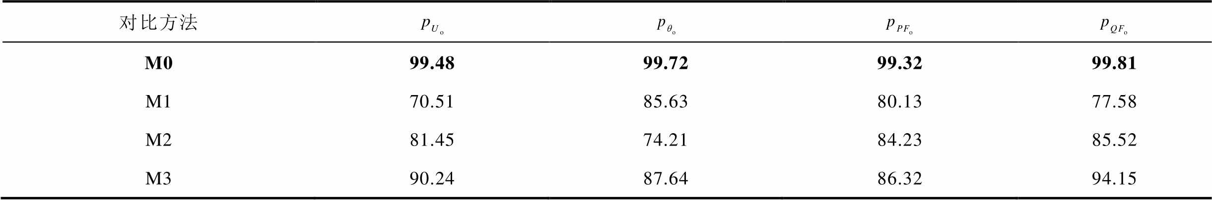
对比方法 M099.4899.7299.3299.81 M170.5185.6380.1377.58 M281.4574.2184.2385.52 M390.2487.6486.3294.15
由表2可知,由M0预测节点电压幅值 、相位
、相位 、支路有功功率
 和支路无功功率
 的精度都高于99%,而M1、M2和M3预测的最高精度分别为85.63%、85.52%以及94.15%。由此说明本文所提模型f能高精度表征N/N-1状态下的潮流耦合关系,为后续对潮流越限运行方式智能调整提供了较为准确的模型。
为验证本文所提电网运行方式智能调整方法的有效性,使用本方法分别对IEEE 30节点系统和某实际大电网341节点系统中存在N/N-1状态下潮流越限的运行方式进行调整。首先对IEEE 30节点系统下存在潮流越限的待调运行方式应用本文方法进行调整,详细调整情况见表3。
表3 IEEE 30节点系统某待调运行方式的详细调整情况
Tab.3 Detailed adjustment situation of a certain operating mode to be adjusted in IEEE 30-bus system
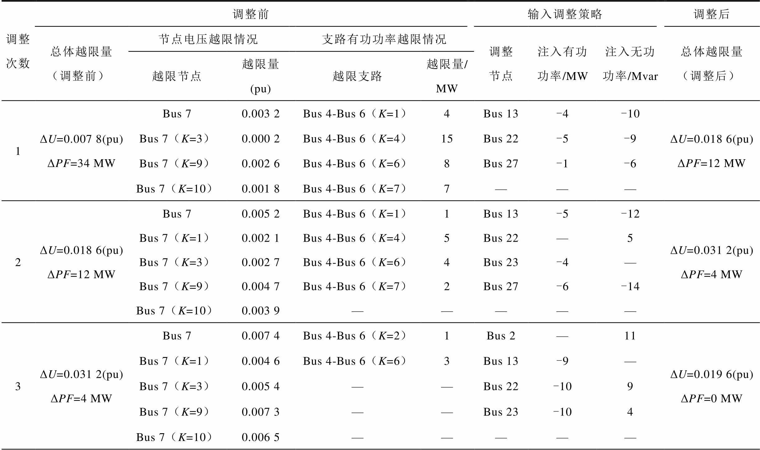
调整次数调整前输入调整策略调整后 总体越限量(调整前)节点电压越限情况支路有功功率越限情况调整节点注入有功功率/MW注入无功功率/Mvar总体越限量(调整后) 越限节点越限量(pu)越限支路越限量/MW 1ΔU=0.007 8(pu)ΔPF=34 MWBus 70.003 2Bus 4-Bus 6(K=1)4Bus 13-4-10ΔU=0.018 6(pu)ΔPF=12 MW Bus 7(K=3)0.000 2Bus 4-Bus 6(K=4)15Bus 22-5-9 Bus 7(K=9)0.002 6Bus 4-Bus 6(K=6)8Bus 27-1-6 Bus 7(K=10)0.001 8Bus 4-Bus 6(K=7)7——— 2ΔU=0.018 6(pu)ΔPF=12 MWBus 70.005 2Bus 4-Bus 6(K=1)1Bus 13-5-12ΔU=0.031 2(pu)ΔPF=4 MW Bus 7(K=1)0.002 1Bus 4-Bus 6(K=4)5Bus 22—5 Bus 7(K=3)0.002 7Bus 4-Bus 6(K=6)4Bus 23-4— Bus 7(K=9)0.004 7Bus 4-Bus 6(K=7)2Bus 27-6-14 Bus 7(K=10)0.003 9————— 3ΔU=0.031 2(pu)ΔPF=4 MWBus 70.007 4Bus 4-Bus 6(K=2)1Bus 2—11ΔU=0.019 6(pu)ΔPF=0 MW Bus 7(K=1)0.004 6Bus 4-Bus 6(K=6)3Bus 13-9— Bus 7(K=3)0.005 4——Bus 22-109 Bus 7(K=9)0.007 3——Bus 23-104 Bus 7(K=10)0.006 5—————
(续)
调整次数调整前输入调整策略调整后 总体越限量(调整前)节点电压越限情况支路有功功率越限情况调整节点注入有功功率/MW注入无功功率/Mvar总体越限量(调整后) 越限节点越限量(pu)越限支路越限量/MW 4ΔU=0.019 6(pu)ΔPF=0 MW(pu)Bus 70.005 7——Bus 2-1113ΔU=0.003 9(pu)ΔPF=0 MW Bus 7(K=3)0.003 9————— Bus 7(K=9)0.005 4————— Bus 7(K=10)0.004 6————— 5ΔU=0.003 9(pu)ΔPF=0 MWBus 70.002 7——Bus 2-97ΔU=0(pu)ΔPF=0 MW Bus 7(K=9)0.001 2—————
注:总体越限量为所有节点电压越限量或支路有功功率越限的总和。
由表3可知,IEEE 30节点系统下待调运行方式的最初越限情况:节点7在N状态下以及在断开第3、9、10条支路的N-1状态下电压越限,最大电压越限量标幺值为0.003 2(pu),总体电压越限量标幺值为0.007 8(pu);支路4-6在断开第1、4、6、7条支路的N-1状态下有功功率越限,最大有功功率越限量为15 MW,总体有功功率越限量为32 MW。通过对抗过程确定了每次输入调整策略,如第1次输入调整策略:节点13、22、27处的发电机有功功率出力调整量分别为-4、-5、-1 MW;节点13、22、27处的发电机无功功率出力调整量分别为-10、-9、-6 Mvar,经过第1次调整后,总体有功功率越限量从调整前的32 MW变为18 MW,整体越限情况呈下降趋势。且从表3中可以得出,按照前3次输入调整策略进行调整后,总体电压越限量标幺值变为0.019 6(pu),总体有功功率越限量从32 MW降至0 MW,支路有功功率不再越限,继续按照最后2次的输入调整策略对运行方式进行调整后,总体电压越限量标幺值从0.019 6(pu)降至0,节点电压也不再越限。最后使用牛顿-拉夫逊法对调整后的运行方式进行校验,证明了按照这5次输入调整策略进行调整后的运行方式满足所有静态N-1安全校验。
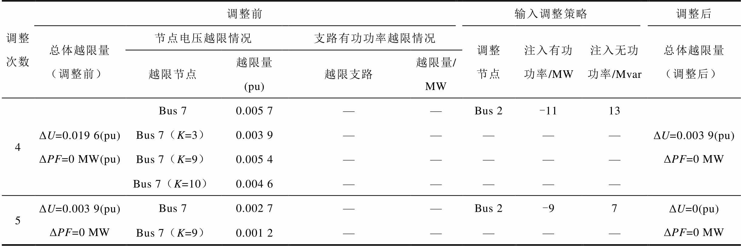
同样对某实际大电网341节点系统下存在潮流越限的待调运行方式应用本文所提方法进行调整,得到详细调整情况见表4。由表4可知该341节点系统下待调运行方式的最初越限情况:支路47-186在N状态下以及在断开第3、6、9、10条支路的N-1状态下有功功率越限,支路52-306在N状态下以及在断开第4、6、7条支路的N-1状态下有功功率越限,最大有功功率越限量为38 MW,总体有功功率越限量为181 MW。通过对抗过程确定了每次输入调整策略,如第1次输入调整策略:节点56、71、81处的发电机有功功率出力调整量分别为-5、-10、-5 MW;节点71、185、320处的发电机无功功率出力调整量分别为6、10、-9 Mvar,经过第1次调整后,总体有功功率越限量从181 MW下降至84 MW,此时最大支路有功功率越限量从38 MW下降至12 MW。按照输入调整策略调整至第3次后,支路52-306的有功功率不再越限,总体有功功率越限量从最初的181 MW降至12 MW,然后按照本方法给出的第4次具体调整策略进行调整后,支路47-186的有功功率也不再越限,总体有功功率越限量从12 MW直接降至0 MW。最后使用牛顿-拉夫逊法对调整后的运行方式进行校验,证明了按照表4中4次具体调整策略进行调整后,该运行方式满足所有静态N-1安全校验。使用该方法模拟人工调整运行方式过程,不仅能得到总体调整策略,而且能得到每次试调后运行方式越限情况的走势,以掌握整个调整过程中运行方式的情况,使获取到的调整策略符合实际调整人员对调整过程的可解释、可接受的需求。
表4 某实际大电网341节点系统某待调运行方式的详细调整情况
Tab.4 Detailed adjustment situation of a certain operating mode to be adjusted of the 341-bus system in an area
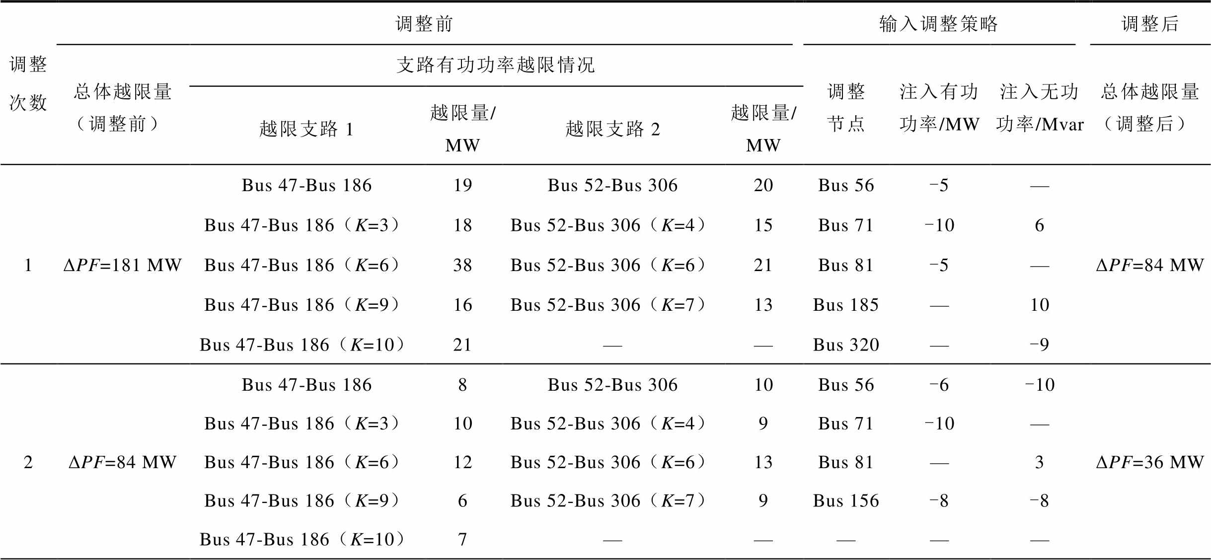
调整次数调整前输入调整策略调整后 总体越限量(调整前)支路有功功率越限情况调整节点注入有功功率/MW注入无功功率/Mvar总体越限量(调整后) 越限支路1越限量/MW越限支路2越限量/MW 1ΔPF=181 MWBus 47-Bus 18619Bus 52-Bus 30620Bus 56-5—ΔPF=84 MW Bus 47-Bus 186(K=3)18Bus 52-Bus 306(K=4)15Bus 71-106 Bus 47-Bus 186(K=6)38Bus 52-Bus 306(K=6)21Bus 81-5— Bus 47-Bus 186(K=9)16Bus 52-Bus 306(K=7)13Bus 185—10 Bus 47-Bus 186(K=10)21——Bus 320—-9 2ΔPF=84 MWBus 47-Bus 1868Bus 52-Bus 30610Bus 56-6-10ΔPF=36 MW Bus 47-Bus 186(K=3)10Bus 52-Bus 306(K=4)9Bus 71-10— Bus 47-Bus 186(K=6)12Bus 52-Bus 306(K=6)13Bus 81—3 Bus 47-Bus 186(K=9)6Bus 52-Bus 306(K=7)9Bus 156-8-8 Bus 47-Bus 186(K=10)7—————
(续)
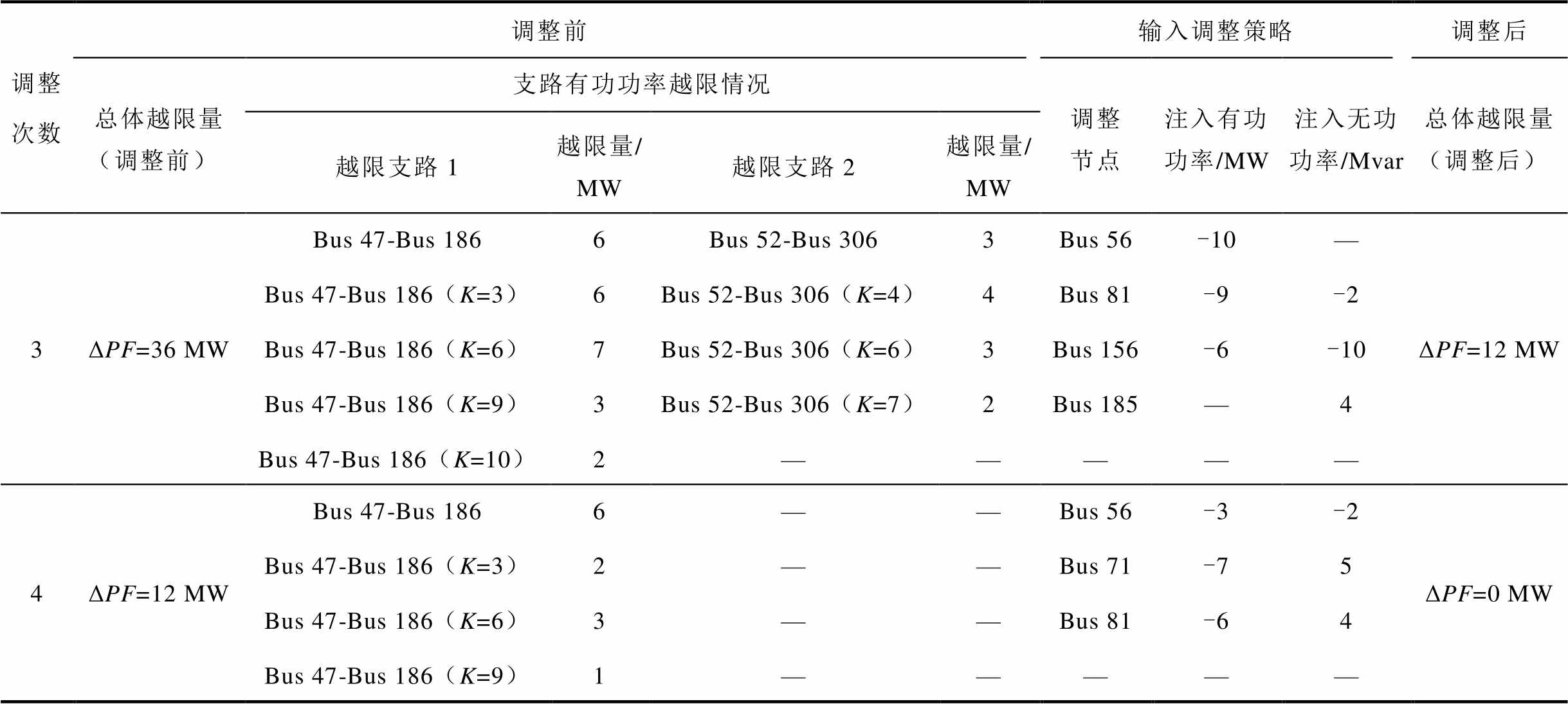
调整次数调整前输入调整策略调整后 总体越限量(调整前)支路有功功率越限情况调整节点注入有功功率/MW注入无功功率/Mvar总体越限量(调整后) 越限支路1越限量/MW越限支路2越限量/MW 3ΔPF=36 MWBus 47-Bus 1866Bus 52-Bus 3063Bus 56-10—ΔPF=12 MW Bus 47-Bus 186(K=3)6Bus 52-Bus 306(K=4)4Bus 81-9-2 Bus 47-Bus 186(K=6)7Bus 52-Bus 306(K=6)3Bus 156-6-10 Bus 47-Bus 186(K=9)3Bus 52-Bus 306(K=7)2Bus 185—4 Bus 47-Bus 186(K=10)2————— 4ΔPF=12 MWBus 47-Bus 1866——Bus 56-3-2ΔPF=0 MW Bus 47-Bus 186(K=3)2——Bus 71-75 Bus 47-Bus 186(K=6)3——Bus 81-64 Bus 47-Bus 186(K=9)1—————
为证明本方法的收敛性,分别对IEEE 30节点系统和某实际大电网341节点系统中1 000个存在潮流越限的待调运行方式应用本文所提方法进行调整,统计出如图6所示的调整后运行方式越限值变化情况。
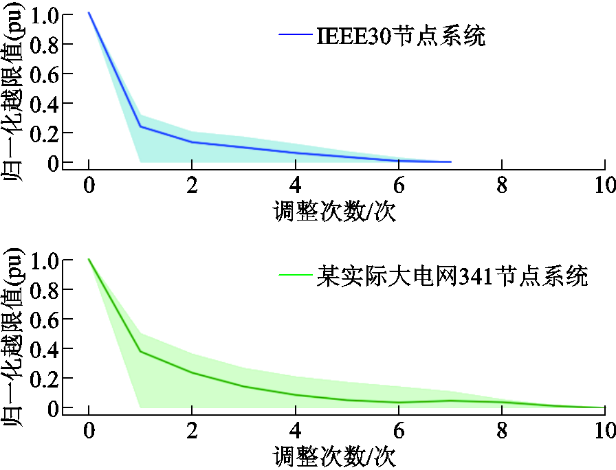
图6 调整后运行方式越限值变化情况
Fig.6 Change of the violation value by adjusting the operation mode
图6中蓝色折线和绿色折线分别表示IEEE 30节点系统和某实际341节点系统中不同调整次数下1 000个运行方式归一化越限值的均值,浅蓝色和浅绿色阴影区域分别表示两系统运行方式归一化越限值的波动范围。由图6可知,通过本文所提方法,两个系统的运行方式归一化越限均值随着调整次数的增加最终都下降到0,并且存在调整1次后就满足安全校核的情况。应用本方法对这些存在潮流越限的运行方式调整至满足静态N-1安全校验,在IEEE 30节点系统中最多仅调整7次,而在某实际341节点系统中最多仅调整了10次,这证明了本方法的普适性和收敛性。
通过将本方法在IEEE 30节点和某实际大电网341节点系统上的应用,证明了其对调整存在N/N-1状态下潮流越限运行方式的有效性。相比只能得到最终调整策略的最优潮流方法,该方法能精准解析调整前后运行方式之间的调整流程,为工作人员在做出运行方式调整决策时提供详细依据。
本文针对N/N-1状态下存在越限的运行方式调整问题,提出了基于N/N-1潮流内嵌图卷积神经网络的电网运行方式智能调整方法。主要内容包括:
1)本文提出了基于N/N-1潮流内嵌的图卷积前向传播策略,利用N/N-1潮流物理模型推导设计神经网络前向传播表达式,有效地提取了运行方式N/N-1状态下的潮流节点特征和支路特征。
2)在图卷积前向传播策略的基础上,本文进一步构建了基于多层图卷积和卷积神经网络模块协同的运行方式N/N-1潮流耦合关系模型,能更有效、精准地表征N/N-1状态下的数据驱动潮流耦合关系。
3)本文提出了基于N/N-1潮流耦合关系的运行方式智能对抗调整方法,通过在IEEE 30节点系统和某实际大电网341节点系统上对其进行验证,证明了本方法能在较少调整次数下,对存在越限的运行方式调整至满足所有静态N-1安全校验,同时精准解析调整前后运行方式之间的调整流程。
后续工作将进一步实际落地本文所提方法,使用大规模实际数据对本文所提方法进行改进,实现对实际电网运行方式的快速智能调整。
参考文献
[1] 张智刚, 康重庆. 碳中和目标下构建新型电力系统的挑战与展望[J]. 中国电机工程学报, 2022, 42(8): 2806-2819.
Zhang Zhigang, Kang Chongqing. Challenges and prospects for constructing the new-type power system towards a carbon neutrality future[J]. Proceedings of the CSEE, 2022, 42(8): 2806-2819.
[2] 国家能源局. 国家能源局综合司关于完善电力系统运行方式分析制度强化电力系统运行安全风险管控的通知:国能综通安全[2023]13号[EB/OL]. (2023-02-17)[2024-06-29]. https://zfxxgk.nea.gov.cn/ 2023-02/17/c_1310700939.htm.
[3] 李军徽, 邵岩, 朱星旭, 等. 计及碳排放量约束的多区域互联电力系统分布式低碳经济调度[J]. 电工技术学报, 2023, 38(17): 4715-4728.
Li Junhui, Shao Yan, Zhu Xingxu, et al. Carbon emissions constraint distributed low-carbon economic dispatch of power system[J]. Transactions of China Electrotechnical Society, 2023, 38(17): 4715-4728.
[4] 杨珺, 侯俊浩, 刘亚威, 等. 分布式协同控制方法及在电力系统中的应用综述[J]. 电工技术学报, 2021, 36(19): 4035-4049.
Yang Jun, Hou Junhao, Liu Yawei, et al. Distributed cooperative control method and application in power system[J]. Transactions of China Electrotechnical Society, 2021, 36(19): 4035-4049.
[5] 高倩, 杨知方, 李文沅. 电力系统混合整数线性规划问题的运筹决策关键技术综述与展望[J]. 电工技术学报, 2024, 39(11): 3291-3307.
Gao Qian, Yang Zhifang, Li Wenyuan. Prospect on operations research for mixed-integer linear programming problems in power systems[J]. Transactions of China Electrotechnical Society, 2024, 39(11): 3291-3307.
[6] 王方雨, 王海云, 于希娟, 等. 考虑越限程度的断面功率灵敏度控制方法[J]. 电网技术, 2023, 47(9): 3847-3855.
Wang Fangyu, Wang Haiyun, Yu Xijuan, et al. Section power sensitivity control considering out-of-limit degrees[J]. Power System Technology, 2023, 47(9): 3847-3855.
[7] 陈海荣, 方健. 一种新能源场站紧急态监控装置的最优化切机算法[J]. 电气技术, 2023, 24(8): 44-49.
Chen Hairong, Fang Jian. An optimal generator tripping method for emergency monitoring and control devices in new energy stations[J]. Electrical Engineering, 2023, 24(8): 44-49.
[8] 吴宇航, 王涛, 范辉, 等. 利用灵敏度分析的规模风电并网系统连锁故障阻断控制[J]. 电网技术, 2023, 47(9): 3743-3755.
Wu Yuhang, Wang Tao, Fan Hui, et al. Blocking control of cascading failures for large-scale wind power system using sensitivity analysis[J]. Power System Technology, 2023, 47(9): 3743-3755.
[9] 陈厚合, 邵俊岩, 姜涛, 等. 基于参数灵敏度的综合能源系统安全控制策略研究[J]. 中国电机工程学报, 2020, 40(15): 4831-4843.
Chen Houhe, Shao Junyan, Jiang Tao, et al. Security control strategy for integrated energy system using parameter sensitivity[J]. Proceedings of the CSEE, 2020, 40(15): 4831-4843.
[10] 曾泓泰, 郭庆来, 周艳真, 等. 面向电网运行方式计算的不收敛潮流无功调整方法[J]. 电力系统保护与控制, 2022, 50(19): 1-12.
Zeng Hongtai, Guo Qinglai, Zhou Yanzhen, et al. Reactive power adjustment method of non-convergent power flow for power system operation mode calculation[J]. Power System Protection and Control, 2022, 50(19): 1-12.
[11] 杨茂, 王金鑫. 考虑可再生能源出力不确定的孤岛型微电网优化调度[J]. 中国电机工程学报, 2021, 41(3): 973-985.
Yang Mao, Wang Jinxin. Optimal scheduling of islanded microgrid considering uncertain output of renewable energy[J]. Proceedings of the CSEE, 2021, 41(3): 973-985.
[12] 李书益. 基于遗传模拟退火粒子群算法的微电网优化运行研究[D]. 南京: 南京邮电大学, 2020.
Li Shuyi. Research on optimal operation of microgrid based on genetic simulated annealing particle swarm optimization algorithm[D]. Nanjing: Nanjing University of Posts and Telecommunications, 2020.
[13] 聂瀚, 杨文荣, 马晓燕, 等. 基于改进鸟群算法的离网微电网优化调度[J]. 燕山大学学报, 2019, 43(3): 228-237.
Nie Han, Yang Wenrong, Ma Xiaoyan, et al. Optimal scheduling of islanded microgrid based on improved bird swarm optimization algorithm[J]. Journal of Yanshan University, 2019, 43(3): 228-237.
[14] 吴熙, 王梦婷, 王亮, 等. 考虑UPFC控制模式的N-1安全约束最优潮流及应用[J]. 电力系统自动化, 2020, 44(9): 43-51.
Wu Xi, Wang Mengting, Wang Liang, et al. N-1 security constrained optimal power flow considering control modes of unified power flow controller and its application[J]. Automation of Electric Power Systems, 2020, 44(9): 43-51.
[15] 张兆毅, 胡浩, 王子江, 等. 基于非线性仿射的风电场电压实时计算和优化方法[J]. 电工技术学报, 2024, 39(13): 3975-3989.
Zhang Zhaoyi, Hu Hao, Wang Zijiang, et al. Real-time voltage calculation and optimization method for wind farms based on nonlinear affine transformation[J]. Transactions of China Electrotechnical Society, 2024, 39(13): 3975-3989.
[16] Wang Licheng, Yang Yu, Gu Huajie, et al. Bottleneck generator identification and the corresponding N-1 frequency security constrained intraday generator dispatch[J]. IEEE Transactions on Power Systems, 2023, 38(1): 739-752.
[17] 林雨眠, 熊厚博, 张笑演, 等. 计及新能源机会约束与虚拟储能的电-热系统分布式多目标优化调度[J]. 电工技术学报, 2024, 39(16): 5042-5059.
Lin Yumian, Xiong Houbo, Zhang Xiaoyan, et al. Distributed multi-objective optimal scheduling of integrated electric-heat system considering chance constraint of new energy and virtual storage[J]. Transactions of China Electrotechnical Society, 2024, 39(16): 5042-5059.
[18] Yang Yan, Yang Zhifang, Yu Juan, et al. Fast economic dispatch in smart grids using deep learning: an active constraint screening approach[J]. IEEE Internet of Things Journal, 2020, 7(11): 11030-11040.
[19] Moreira A, Valenzuela A, Heleno M. Solving market-based large-scale security-constrained AC optimal power flows[J]. IEEE Transactions on Power Systems, 2023, 38(6): 5088-5101.
[20] 王甜婧, 汤涌, 王兵, 等. 传统方法与人工智能:潮流控制优化算法的现状、挑战与未来方向[J]. 中国电机工程学报, 2023, 43(5): 1799-1818.
Wang Tianjing, Tang Yong, Wang Bing, et al. Traditional methods versus artificial intelligence: optimization algorithms for power flow control in state of the art, challenge and future directions[J]. Proceedings of the CSEE, 2023, 43(5): 1799-1818.
[21] 冉晴月, 林伟, 杨知方, 等. 基于可信深度神经网络的最优潮流计算方法[J]. 电工技术学报, 2024, 39(21): 6687-6699.
Ran Qingyue, Lin Wei, Yang Zhifang, et al. Optimal power flow calculation based on a trustworthy deep neural network[J]. Transactions of China Electro-technical Society, 2024, 39(21): 6687-6699.
[22] 张松涛, 张东霞, 黄彦浩, 等. 基于改进直流潮流算法的潮流计算收敛自动调整方法研究[J]. 电网技术, 2021, 45(1): 86-97.
Zhang Songtao, Zhang Dongxia, Huang Yanhao, et al. Research on automatic power flow convergence adjustment method based on modified DC power flow algorithm[J]. Power System Technology, 2021, 45(1): 86-97.
[23] 杨晓东, 严剑峰, 刘佳霖. 结合深度强化学习与人工经验的电网输电断面功率调整方法[J]. 电力系统自动化, 2023, 47(15): 133-141.
Yang Xiaodong, Yan Jianfeng, Liu Jialin. Power adjustment method for transmission section in power grid combining deep reinforcement learning and artificial experience[J]. Automation of Electric Power Systems, 2023, 47(15): 133-141.
[24] Yan Ziming, Xu Yan. A hybrid data-driven method for fast solution of security-constrained optimal power flow[J]. IEEE Transactions on Power Systems, 2022, 37(6): 4365-4374.
[25] Liu Tingjian, Liu Youbo, Liu Junyong, et al. A Bayesian learning based scheme for online dynamic security assessment and preventive control[J]. IEEE Transactions on Power Systems, 2020, 35(5): 4088-4099.
[26] Duan Jiajun, Shi Di, Diao Ruisheng, et al. Deep-reinforcement-learning-based autonomous voltage control for power grid operations[J]. IEEE Transactions on Power Systems, 2020, 35(1): 814-817.
[27] 胡丹尔, 彭勇刚, 韦巍, 等. 多时间尺度的配电网深度强化学习无功优化策略[J]. 中国电机工程学报, 2022, 42(14): 5034-5045.
Hu Daner, Peng Yonggang, Wei Wei, et al. Multi-timescale deep reinforcement learning for reactive power optimization of distribution network[J]. Proceedings of the CSEE, 2022, 42(14): 5034-5045.
[28] 张剑, 崔明建, 何怡刚. 结合数据驱动与物理模型的主动配电网双时间尺度电压协调优化控制[J]. 电工技术学报, 2024, 39(5): 1327-1339.
Zhang Jian, Cui Mingjian, He Yigang. Dual timescales coordinated and optimal voltages control in distribution systems using data-driven and physical optimization [J]. Transactions of China Electrotechnical Society, 2024, 39(5): 1327-1339.
[29] 王甜婧, 汤涌, 郭强, 等. 基于知识经验和深度强化学习的大电网潮流计算收敛自动调整方法[J]. 中国电机工程学报, 2020, 40(8): 2396-2406.
Wang Tianjing, Tang Yong, Guo Qiang, et al. Automatic adjustment method of power flow calculation convergence for large-scale power grid based on knowledge experience and deep reinforcement learning[J]. Proceedings of the CSEE, 2020, 40(8): 2396-2406.
[30] Gao Maosheng, Yu Juan, Yang Zhifang, et al. A physics-guided graph convolution neural network for optimal power flow[J]. IEEE Transactions on Power Systems, 2024, 39(1): 380-390.
[31] Dong Yinpeng, Liao Fangzhou, Pang Tianyu, et al. Boosting adversarial attacks with momentum[C]// 2018 IEEE/CVF Conference on Computer Vision and Pattern Recognition, Salt Lake City, UT, USA, 2018: 9185-9193.
[32] Duan Shiqi, Yu Juan, Yang Zhifang, et al. An intelligent power flow violation adjustment method based on adversarial process[C]//2023 IEEE 7th Conference on Energy Internet and Energy System Integration (EI2), Hangzhou, China, 2023: 4774-4779.
[33] Gao Maosheng, Yu Juan, Yang Zhifang, et al. Physics embedded graph convolution neural network for power flow calculation considering uncertain injections and topology[J]. IEEE Transactions on Neural Networks and Learning Systems, 2024, 35(11): 15467-15478.
[34] Yang Zhifang, Xie Kaigui, Yu Juan, et al. A general formulation of linear power flow models: basic theory and error analysis[J]. IEEE Transactions on Power Systems, 2019, 34(2): 1315-1324.
[35] Lei Yunwen, Tang Ke. Learning rates for stochastic gradient descent with nonconvex objectives[J]. IEEE Transactions on Pattern Analysis and Machine Intelligence, 2021, 43(12): 4505-4511.
[36] Goodfellow I J, Shlens J, Szegedy C. Explaining and harnessing adversarial examples[C]//Proceedings of the 3rd International Conference on Learning Representations,San Diego City, CA, USA, 2015.
Abstract The adjustment of the operation mode is crucial for ensuring the safety and stability of the power grid, and manual adjustment is still the main method in current industry practices. However, with the integration of numerous renewable energy sources and the application of power electronic equipment, both the scale and complexity of the power grid continue to increase, resulting in the manual adjustment method that relies on manual experience to adjust repeatedly by trial-and-error method faces the following severe challenges: low efficiency, lack of theoretical guidance. Recently, some methods for operation mode adjustment have been proposed, but most of them cannot provide the transition process and intrinsic connection between the operation modes before and after the adjustment, making it difficult for the staff to explain and analyze the operation mode adjustment issues, which affects the decision-making efficiency. To solve these problems, this paper proposes an intelligent adjustment method of power grid operation mode based on N/N-1 power flow embedded graph convolutional neural network (GCNN).
Firstly, the forward propagation expression of the convolutional module of the design diagram is derived from the N/N-1 power flow physical model, and the convolutional forward propagation strategy based on N/N-1 power flow embedding is proposed to effectively extract the node and branch features of the power system in N/N-1 conditions. Then, taking power flow characteristics in N/N-1 conditions as input/output characteristics, the N/N-1 power flow coupling model based on multi-layer graph convolution and convolutional neural network module collaboration is constructed to characterize the data-driven power flow coupling relationship in N/N-1 conditions. Next, aiming at the operation mode of power flow exceeding the limit under N/N-1 conditions, an intelligent adversarial adjustment method based on N/N-1 power flow coupling relationship is proposed to accurately analyze the adjustment process before and after the adjustment and obtain the effective adjustment strategy for the operation mode, achieving the adjustment of the operation mode of power flow exceeding the limit under N/N-1 conditions to meet the N-1 verification.
The simulation results on the IEEE 30-bus system show that the accuracy of the proposed N/N-1 power flow coupling model for predicting the nodal voltage magnitude, phase angle, branch active power, and reactive power is 99.48%, 99.72%, 99.32%, and 99.81% respectively, which is higher than that of the prediction models constructed based on other neural network architectures (fully connected neural network, convolutional neural network, graph convolutional neural network), indicating that the proposed model can accurately characterize the power flow coupling relationship under N/N-1 conditions. To verify the effectiveness of the proposed intelligent adjustment method for power grid operation mode, the operation mode with power flow limit exceeding in the IEEE 30-bus system and 341-bus system in an area is adjusted, and the adjustment process before and after the adjustment can be accurately analyzed, and the effective adjustment strategy for the operation mode can be obtained. Finally, to prove the convergence of this method, the proposed method is applied to adjust 1000 operation modes with power flow limit exceeding in the two power systems, and the results show that these operation modes can be adjusted to meet the N-1 verification with fewer adjustment times.
The following conclusions can be drawn from the simulation analysis: (1) Compared with the models based on fully connected neural network, convolutional neural network and graph convolutional neural network architectures, the proposed N/N-1 power flow coupling model can more effectively and accurately characterize the power flow coupling relationship under N/N-1 conditions. (2) The proposed intelligent adversarial adjustment method can adjust the operation mode with limit exceeding to meet all static N-1 verification with fewer adjustment times and accurately analyze the adjustment process between the operation modes before and after the adjustment, and it provides the detailed basis for the staff to make the decision of operation mode adjustment.
Keywords: Operation mode adjustment, N-1 verification, graph convolutional neural network, power flow embedded, adversarial process
中图分类号:TM761
DOI: 10.19595/j.cnki.1000-6753.tces.241728
国家电网有限公司科技资助项目(5100-202427022A-1-1-ZN)。
收稿日期 2024-10-07
改稿日期 2024-12-23
段师琪 女,2002年生,硕士研究生,研究方向为人工智能在电力系统运行方式分析中的应用、深度学习。E-mail:3179616534@qq.com
余 娟 女,1980年生,博士,教授,研究方向为电力与能源经济优化运行、风险评估、深度学习等。E-mail:yujuancqu@cqu.edu.cn(通信作者)
(编辑 赫 蕾)