 (1)
(1)
摘要 无速度传感器感应电机在低速发电区域运行时,其转速估算系统会变得不稳定。然而,传统稳定性提升方法无法完全消除系统的不稳定特征值,因此难以彻底解决运行不稳定的问题。为此,该文提出一种基于特征值分布的无传感器感应电机低速发电区域稳定性提升策略。首先,考虑误差系数矩阵的特征值分布,分析将定子电流作为反馈量的传统方法,证明了不稳定特征值在同步速为零工作点附近的恒存在性。其次,在转速自适应律和观测器中同时引入定子电流误差与转子磁链误差,建立多重误差全阶观测器模型。然后,根据误差系数矩阵的行列式与迹设计反馈增益,并结合特征值分布法确定其具体数值,使误差系数矩阵实现特征值稳定分布。此外,分析定子电阻失配对估计磁链的影响,提供增强系统鲁棒性的反馈增益设计方向。最后,通过在2.2 kW感应电机实验平台上进行转矩阶跃、转速反转与加速至额定转速实验,验证所提出方法的有效性。
关键词:特征值分布 无速度传感器 感应电机 稳定性 磁链误差
在轨道交通领域,车辆牵引感应电机系统依靠速度传感器确保系统的精度,但随之而来的是昂贵的传感器安装和维护成本以及易受环境影响的控制精度[1]。为了提高牵引传动系统的可靠性以及降低系统维护的成本,无速度传感器控制技术得到广泛使用,逐渐成为轨道列车牵引传动控制的核心技术之一[2]。但当感应电机运行在低速发电区域内时,其转速估算系统会变得不稳定,这种不稳定性将限制其应用[3]。针对上述问题,国内外的专家们主要提出了两类解决方法[4]:
(1)异向性法。文献[5]通过Teager-Kaiser能量算子解调方法对定子电流进行解调,并在此基础上使用调制滑动离散时间傅里叶变换频谱分析方法通过谱峰估计转速,提高了转速的估算精度,提升了系统稳定性。文献[6]在双三相感应电机的两套定子绕组中注入相位相反的高频信号,跟踪谐波子空间中由磁路饱和引起的高频定子漏磁路的凸极,提升了电机在低速工况下的高转矩输出能力。文献[7]通过测量零序电流的倒数来跟踪由于饱和或转子开槽引起的漏感变化,以响应电压测试矢量,实现了在低频和零频下对无传感器感应电机的控制。文献[8]利用感应电机的磁路饱和特性,向定子电压中注入高频旋转电压,通过检测定子电流中的高频成分,实现无传感器感应电机在低速段带重载运行工况下的精确转速控制。文献[9]在观测器中注入虚拟电压,提出了基于最优轨迹的切换结构,实现了平滑快速的转换,保证了系统在低速范围内的稳定性。然而,这种基于电机异向性的稳定性提升方法容易造成转速观测误差和转矩脉动[10]。
(2)模型法。目前,使用较广泛的模型法有扩展卡尔曼滤波器[11]、滑模观测器[12]、模型参考自适应系统(Model Reference Adaptive System, MRAS)[13]、自适应全阶观测器(Adaptive Full Order Observer, AFO)[14]等。文献[15]对传统卡尔曼滤波器进行了扩阶处理,提出了基于定子电阻参数辨识扩展卡尔曼滤波器协同负载扰动观测器的转速辨识方法,提高了感应电机在低速运行中的稳态和动态性能。文献[16]提出了一种基于经典转子磁通的MRAS,该系统使用电压参考矢量来计算参考模型中的转子磁通矢量,提升了无速度传感器感应电机的低速性能。文献[17]基于小信号模型计算得出了传统MRAS的不稳定区域,并依此提出了改进型的MRAS,该改进模型可以使感应电机实现全范围稳定。而对于AFO来说,一般会从两个方面改善系统的稳定性,一方面是设计反馈增益,另一方面是改善转速自适应律。文献[18]在转速自适应律上增加校正项,同时以极点平移法为基础,提出反馈矩阵的简化方案,改善了低速及高速范围内的转速跟随效果,提升了转矩与定子电流的观测精度。文献[19]结合转矩-转速平面中的不稳定特征值分布,在转速自适应律中引入移相角,使低速发电不稳定区域的两条边界线重合,从而消除不稳定区域。文献[20]提出一种基于最小励磁电流误差原则的设计理念来设计反馈增益,并在此基础上引入励磁电流误差与合适的权系数改善转速自适应律,从而改善系统的稳定性特性。通过以上方法,无速度传感器感应电机低速发电不稳定的问题得到了一定改善,但是由于模型法自身的组成结构问题,从误差系数矩阵特征值分布的角度来看,传统方法无法完全消除不稳定的特征值。
针对上述问题,本文提出了一种基于特征值分布的无速度传感器感应电机低速发电区域稳定性提升策略。传统方法中的AFO仅仅引入定子电流误差作为反馈量,无法使感应电机系统实现特征值的稳定分布。因此,本文首先在转速自适应律和AFO中协同引入定子电流误差和磁链误差,建立多重误差AFO模型,消除传统稳定性提升方法中误差系数矩阵的不稳定特征值。其次基于特征值分布法,设计与定子电流误差和转子磁链误差相对应的反馈增益,使矩阵特征值均分布在特征平面左半平面。然后基于估计磁链与实际磁链的比值,分析系统对于定子电阻的鲁棒性,提供增强系统鲁棒性的反馈增益设计方向。最后通过实验验证了所提方法可以有效增强感应电机在低速发电区域的稳定性与带载能力,实现感应电机的稳定运行。
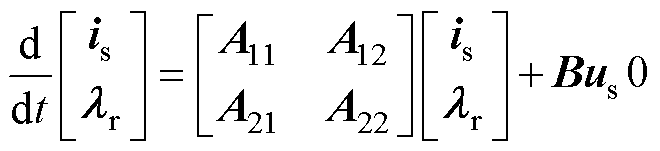
选取定子电流与转子磁链为状态变量,建立感应电机在两相静止ab 坐标系下的数学模型为
(1)
其中
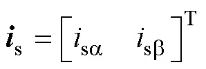
式中, 为定子电流;
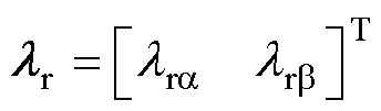
 为转子磁链;
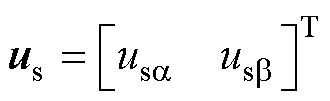
 为定子电压;
 、
、 、
、 、
、 、
、 分别为定子电阻、转子电阻、定子电感、转子电感、互感;
 为转子转速;Tr为转子时间常数。
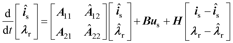
感应电机的数学模型类似,引入定子电流误差,传统AFO的数学模型可以表示为
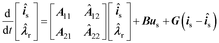 (2)
(2)
其中
式中,G为反馈矩阵; 、
、 、
、 、
、 为反馈矩阵增益;“
 ”表示估计值;
 和
和 为把
为把 和
和 中的实际转速替换成估计转速
 后所得的系数矩阵。
将式(1)减去式(2)可以得到误差矢量方程为
 (3)
(3)
其中

式中, 为定子电流误差;
 为转子磁链误差;
 为转速误差。
基于波波夫超稳定性定理,当系统保持渐近稳定时,满足
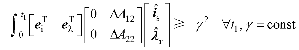 (4)
(4)
式中, 为任意时刻;
 为系统的稳定性裕度。
因此,可以推导出转速自适应律为
 (5)
(5)
式中, 为比例增益;
 为积分增益。
为了简化分析,忽略转子磁链误差,则转速自适应律被简化为
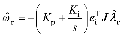 (6)
(6)
为了分析无速度传感器感应电机驱动系统的稳定性,在式(3)中加入转速误差,扩展误差矢量为
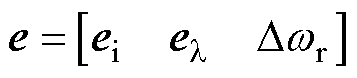 (7)
(7)
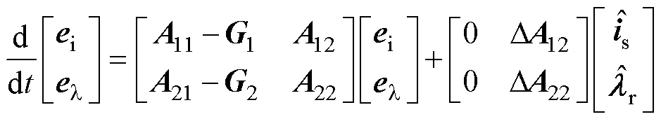
然后,将式(7)中的扩展误差矢量在两相旋转dq坐标系中的工作点上线性化为
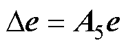 (8)
(8)
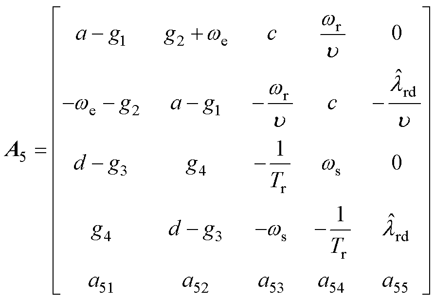

式中, 为扩展误差矢量的微分形式;
 为误差系数矩阵;
 为同步转速;
 为滑差转速;
 为d轴转子磁链观测值。
当无速度传感器感应电机驱动系统稳定时,误差系数矩阵的特征根应该都分布在特征平面左半平面。即若假设误差系数矩阵的特征根为
 (9)
(9)
则系统稳定的充分必要条件为
 (10)
(10)
基于式(10),可以得到系统稳定的必要条件为
 (11)
(11)
求解误差系数矩阵的行列式可得
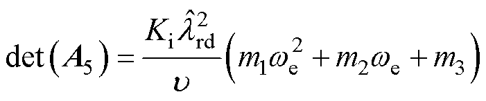 (12)
(12)
其中
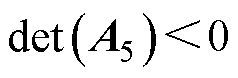
式中,det(A5)可以看作是一个关于的抛物线函数,若要感应电机在运行过程中均满足式(11),则需要det(A5)为开口向下,且最大值小于零的抛物线函数。但由于,则当 ,即当电机运行在低速发电不稳定区域时,det(A5)=0,并不满足式(11)。且当抛物线开口向下,即
 时,det(A5)的最大值
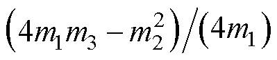 ≥0,这代表在的某个邻域内,det(A5)≥0。因此,从误差系数矩阵特征根分布这一角度来看,传统的全阶观测器反馈矩阵设计并不能解决无速度传感器感应电机在低速发电区域内运行不稳定的问题。
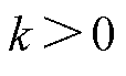
由于误差系数矩阵特征值的具体数值无法直接计算出来,因此通过特征值分布法来观察其特征值分布情况。文献[21]仅引入定子电流误差为反馈量,基于劳式判据设计反馈矩阵,其误差系数矩阵的特征值分布如图1所示,在电机转速由-4p rad/s变化到4p rad/s,滑差转速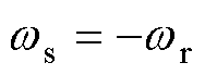 时,感应电机工作在低速发电不稳定区。在误差系数矩阵的五个特征值中,x1、x2、x3、x5的实部均小于0,但是当电机转速变化时,有将近一半的工况下,特征值x4的实部均大于0。这些分布在特征值平面右半平面的特征值会导致电机的不稳定运行。因此,仅引入定子电流误差的传统反馈矩阵设计方法无法彻底解决低速发电区域不稳定的问题。
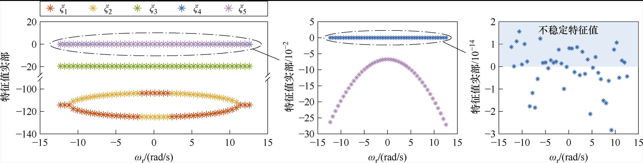
图1 基于劳式判据的误差系数矩阵特征根分布随wr的变化
Fig.1 Variation of the distribution of the eigenvalues of the error coefficient matrix based on the routh criterion with wr
基于1.3节中稳定性分析可知,在全阶观测器中引入电流误差并不能完全解决感应电机在低速发电区域内运行不稳定的问题。为了解决上述问题,在观测器同时引入定子电流误差和转子磁链误差,建立多重误差AFO模型,根据误差系数矩阵特征值分布设计反馈增益。
由于转子磁链实际值无法获取,因此需要通过已知量的转换式得到。基于式(1),可以推导出在复频域中,实际转子磁链与定子电流的关系[22]为
 (13)
(13)
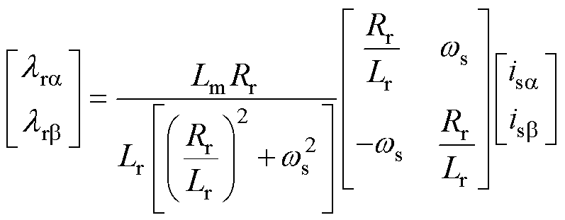
故转子磁链误差可以表示为
 (14)
(14)
因此,基于定子电流误差与转子磁链误差的全阶观测器模型可表示为
 (15)
(15)
其中
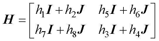
式中,h1~h8为反馈矩阵增益。
令
 (16)
(16)
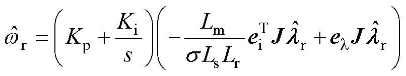
相应地,基于式(5),考虑磁链误差的转速自适应律可表示为
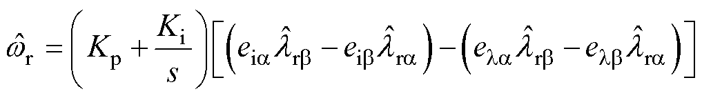 (17)
(17)
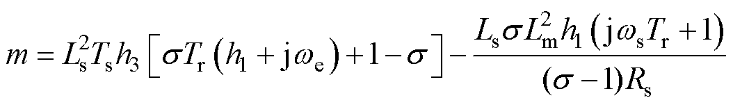
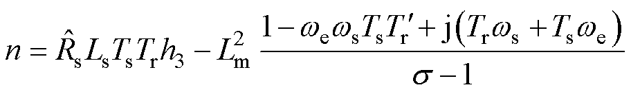
为了简化计算,求解基于电流与磁链误差的全阶观测器的误差系数矩阵为
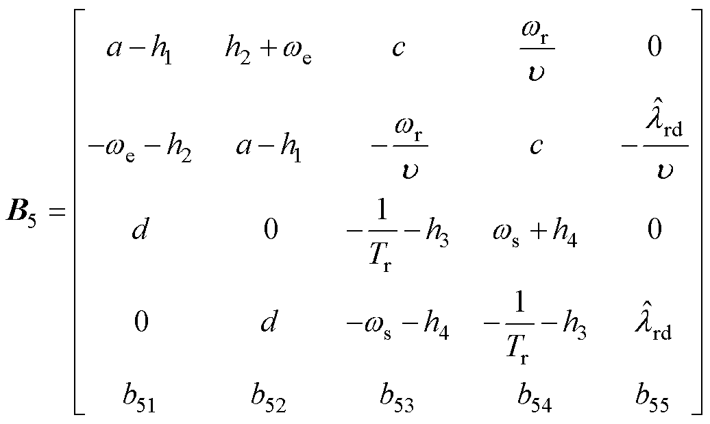 (18)
(18)
其中
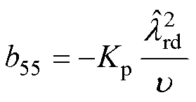
当反馈矩阵的设计满足时,其必定满足矩阵B5的行列式和迹均小于0,即
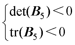 (19)
(19)
式(19)可具体化为
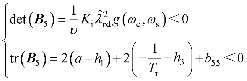 (20)
(20)
其中
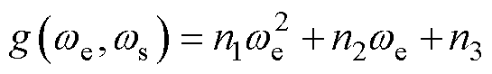

相应地, 需要为开口向下且最大值小于0的抛物线,则对于反馈增益的约束条件为
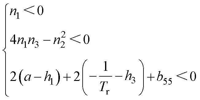 (21)
(21)
基于式(21),可以设计反馈增益为
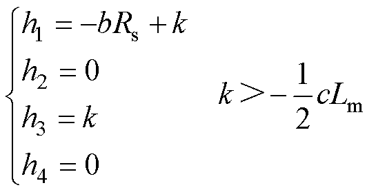 (22)
(22)
式中,k为增益变量。
设定转速从-4p rad/s变化到4p rad/s,同步转速为0,k值从 变化到
变化到 ,绘制误差系数矩阵的特征值分布如图2所示。
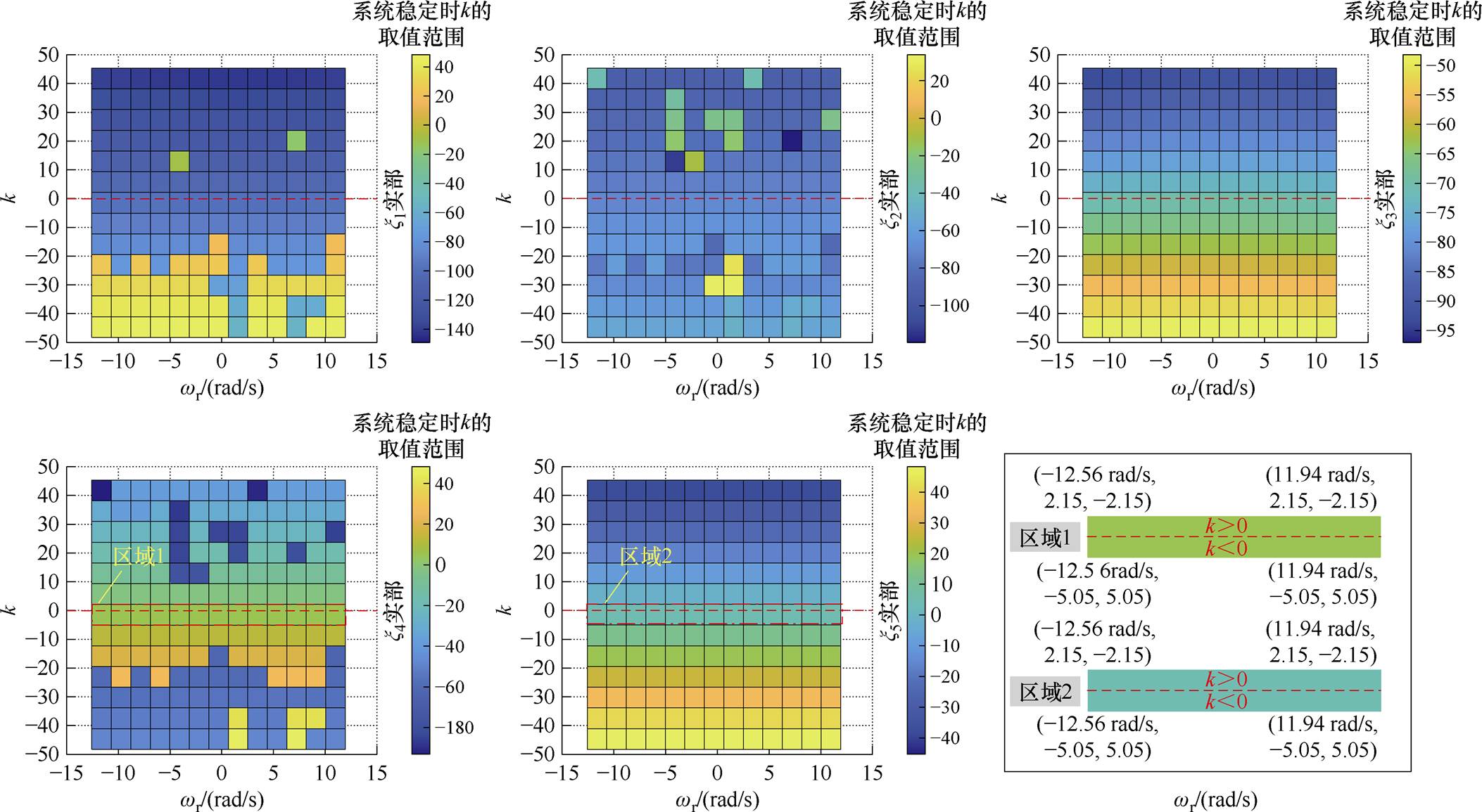
图2 误差系数矩阵B5特征根实部随电机转速wr和增益变量k的变化
Fig.2 Variation of the real part of eigenvalues of the error coefficient matrix B5 with motor speed wrand gain variable k
从图2中可以看出,当k<0时,x1、x2、x3的实部不全小于0。对于特征值x4,当电机转速为-12.56 rad/s、滑差转速为12.56 rad/s时,其实部为5.05,大于0;当电机转速为11.94 rad/s,滑差转速为-11.94 rad/s时,其实部为5.05,也大于0。
当k>0时,x1、x2、x3的实部明显均小于0。对于特征值l4,当电机转速为-12.56 rad/s、滑差转速为12.56 rad/s时,其实部为-2.15,小于0;当电机转速为11.94 rad/s,滑差转速为-11.94 rad/s时,其实部为-2.15,也小于0。特征值x5与特征值x4在实部为0附近的情况类似。
因此,为了保证无速度传感器感应电机在低速发电区域的稳定运行,需要保证所有特征值的实部均小于0,即反馈增益需满足
 (23)
(23)
为了与1.3节中的分析形成对比,采用式(22)中的反馈增益在与1.3节相同的条件下进行特征值分布的绘制,结果如图3所示。
图3 使用提出方法时误差系数矩阵特征根分布随wr变化
Fig.3 Variation of error coefficient matrix eigenvalues distribution with wr when using the proposed method
从图3中可以看出,在相同的工作条件下,相比于传统方法,本文中所提出的方法可以使所有特征值的实部均小于0,不存在不稳定的特征值,由此可以证明本文所提方法的有效性。
在无速度传感器感应电机驱动系统中,定子电阻参数受温度影响较大,易产生定子电阻误差。而定子电阻误差会影响估计磁链,从而影响估计转速。当定子电阻参数不匹配时,估计转子磁链与实际转子磁链的比值为
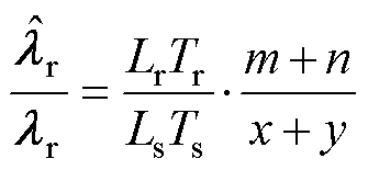 (24)
(24)
其中


式中,Ts为定子时间常数; 为定子电阻失配值。
设定电机转速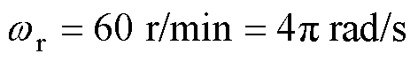 ,滑差转速
,滑差转速 由-4p rad/s变化到-5.38p rad/s,定子电阻误差分别设置为30%和-30%,绘制估计磁链与实际磁链的比值如图4所示。
由图4可见,当定子电阻存在误差,且k值较小,滑差转速较大时,估计磁链与实际磁链的幅值差异较大,最大接近8倍,此时无速度传感器感应电机驱动系统对定子电阻的变化较为敏感,而k值的增加可以减少此差异。因此,k值的增大可以减小定子电阻误差对估计磁链的影响,从而提升系统鲁棒性。
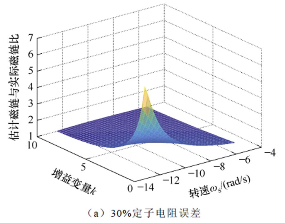
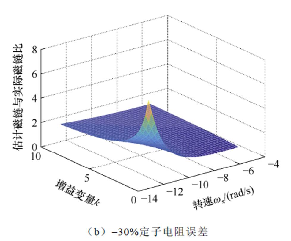
图4 定子电阻不匹配时估计磁链与实际磁链之比
Fig.4 Ratio of estimated to actual rotor flux for stator resistance mismatch
为了验证本文提出策略的有效性,使用基于STM32F103的2.2 kW感应电机平台进行实验。实验平台如图5所示,实验中所用感应电机的具体参数见表1。实验中使用的PWM波频率为6 kHz。励磁电流设定为额定电流的50%,转速自适应律中的Kp=1,Ki=60,测试电机采用无传感器矢量控制,负载电机采用直接转矩控制。
图5 2.2 kW感应电机实验平台
Fig.5 2.2 kW induction motor experimental setup
感应电机保持恒定转速并带上发电负载时,随着负载转矩的阶跃改变,电机会逐渐运行到低速发电不稳定区。设定电机转速保持在60 r/min,发电负载转矩从0 N·m开始,每隔4 s以1.7 N·m的步长进行阶跃变化,实验时长为32 s。当负载转矩达到6.8 N·m时,感应电机开始进入低速发电不稳定区。
表1 2.2 kW感应电机参数
Tab.1 2.2 kW induction motor parameters
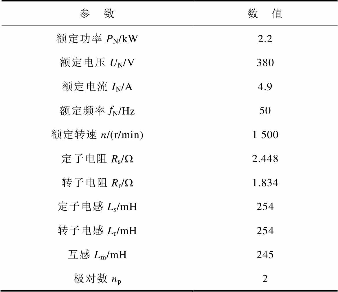
参 数数 值 额定功率PN/kW2.2 额定电压UN/V380 额定电流IN/A4.9 额定频率fN/Hz50 额定转速n/(r/min)1 500 定子电阻Rs/W2.448 转子电阻Rr/W1.834 定子电感Ls/mH254 转子电感Lr/mH254 互感Lm/mH245 极对数np2
图6所示为负载阶跃变化的实验结果,实验中观测的波形为负载转矩、估计转速、实际转速和相电流。分别使用无反馈矩阵的方法、文献[21]中的传统方法及本文所提方法进行对比实验。
由图6a~图6c的对比可知,当反馈矩阵为0时,估计转速在负载转矩增加到5.1 N·m时就不再收敛,且最大相电流达到了22.9 A,远远超出额定电流,然而此时电机仍然工作在稳定区域。当使用文献[21]中的传统方法时,电机只能在6.8 N·m及以下的负载转矩保持稳定运行,当负载转矩达到8.5 N·m时,转速开始发散,且此时相电流最大达到了21.3 A,这证明传统方法对感应电机在低速发电区域的不稳定问题有优化效果,但效果较差。而当使用所提方法时,负载转矩可以持续增加到11.9 N·m,此时估计转速仍可以收敛于实际转速,且相电流几乎无波动。
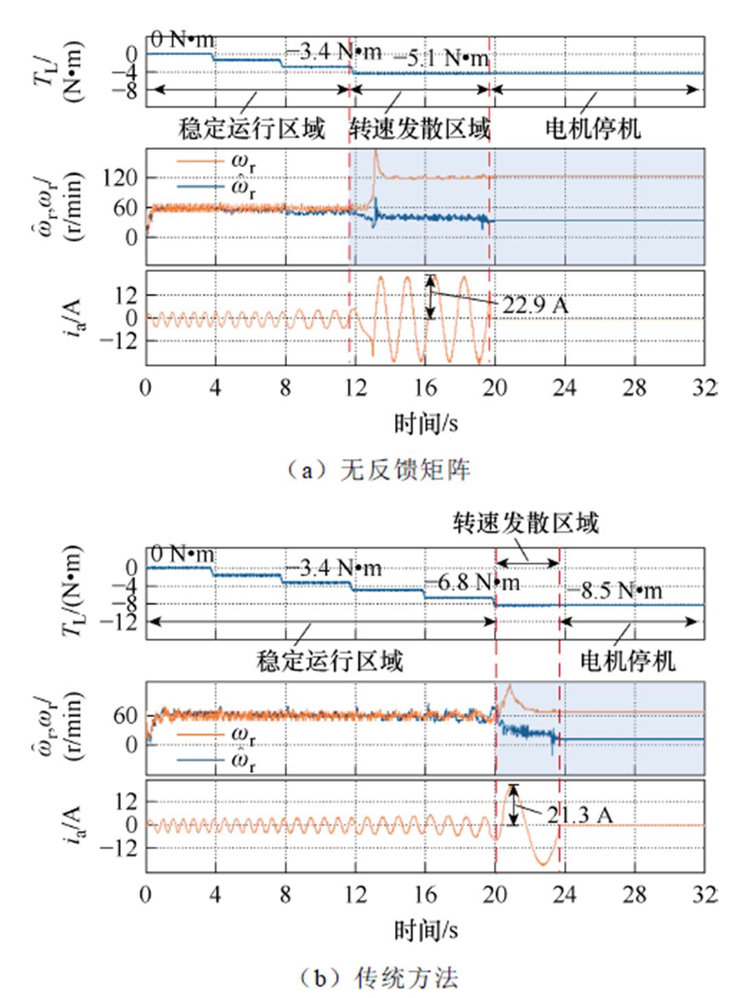
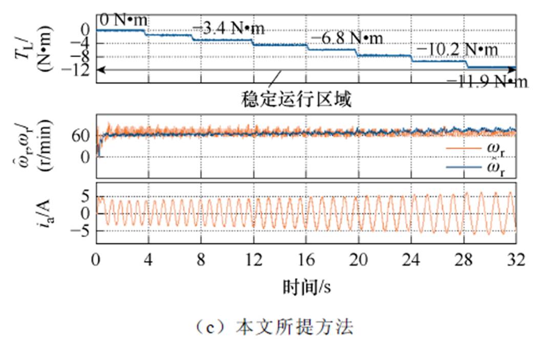
图6 低速发电工况下负载阶跃变化的实验结果
Fig.6 Experimental results during load step changes in low-speed regenerating region
实验过程对应的电机运行工作点变化如图7所示。由图可见,相比于无反馈矩阵的方法和传统方法,所提方法可以扩大无速度传感器感应电机在原始低速发电不稳定区域的可稳定运行范围。
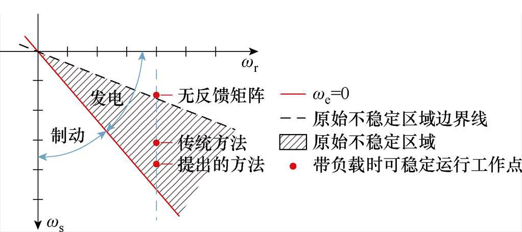
图7 使用不同方法时电机运行工作点变化
Fig.7 Changes in motor operation operating point when using different methods
因此,本文提出的方法可以更好地增强电机在低速区域内的带载能力,增强了其在低速发电区域内的稳定性。
为进一步验证所提方法的有效性,开展转速切换对比实验。类似地,分别使用无反馈矩阵的方法、文献[21]中的传统方法及本文所提方法进行对比实验。转速反转的时间为3 s,实验结果如图8所示。
在实验过程中,转速一共进行两次反转。分别为从150 r/min反转到-150 r/min,再从-150 r/min反转到150 r/min。通过图8a~图8c的对比可知,当反馈矩阵被设置为0时,转速无法反转成功,且此时最大相电流达到了20.8 A;当使用传统方法时,转速的第一次反转成功,但当电机穿越零频工作点时,转速有很大的波动,其估计转速波动的峰峰值达到了463 r/min,且最大相电流达到了13.02 A,证明此时电机工作状况较不稳定,而电机第二次反转的失败进一步证实了电机运行的不稳定性。这两次实验中相电流都远远超过了额定电流,故在实际应用中不使用反馈矩阵与使用传统方法时均容易损坏电机。
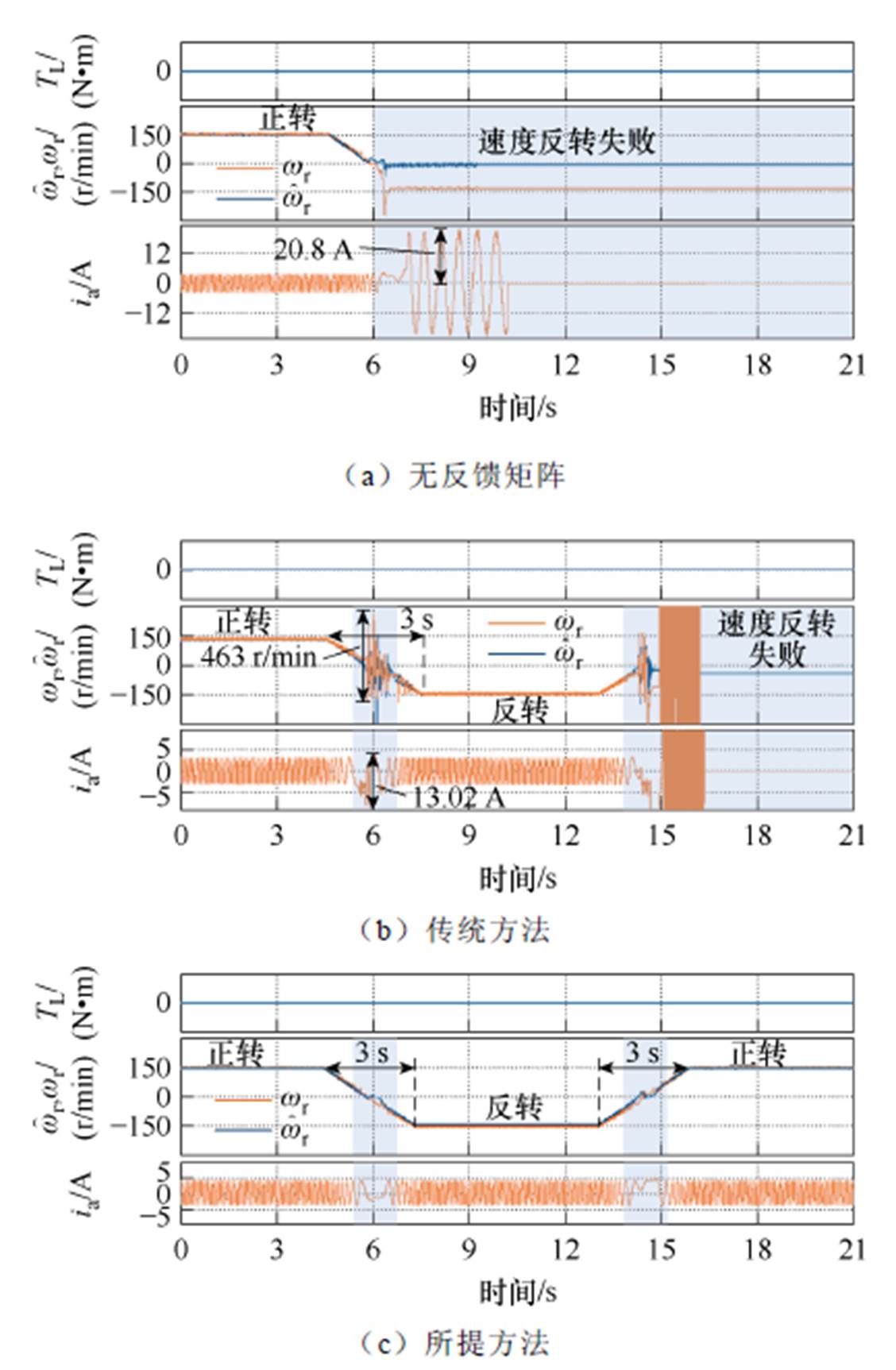
图8 转速反转实验
Fig.8 Speed reversal results
当使用所提出的方法时,电机在两次转速反转过程中估计转速与实际转速之间几乎无差别,且转速波动很小,相电流也控制在额定电流之内。这证明了所提方法可以很好地保持转速在低速发电区域的稳定性,以及抑制相电流与估计转速的波动。
最后,使用所提方法进行转速从0递加到额定转速的实验,加速时间为20 s,带空载运行,实验结果如图9所示。当电机转速大于180 r/min时,反馈矩阵被设为0。由图9可知,在电机加速及稳定运行过程中,估计转速精确地收敛于实际转速,证实了所提出方法的有效性。
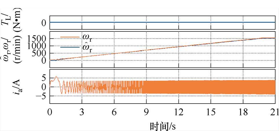
图9 加速至额定转速实验结果
Fig.9 Result during acceleration to rated speed
本文提出了一种基于特征值分布的无速度传感器感应电机低速发电区域稳定性增强方法。对传统方法中误差系数矩阵的行列式的分析表明,仅仅在全阶观测器中引入定子电流误差不足以完全消除不稳定特征值。因此,本文在全阶观测器和转速自适应律中同时引入定子电流误差和磁链误差,建立了多重误差全阶观测器模型。同时,基于特征值分布法设计了新的反馈增益,该反馈增益可实现误差系数矩阵特征值的稳定分布。此外,分析定子电阻误差对估计磁链产生的影响,提出通过适当增加反馈增益中的k值来提升系统鲁棒性的方法。实验表明,该方法可以使感应电机在低速区域带发电负载能力由6.8 N·m提升至11.9 N·m,且可以有效抑制在转速反转时的相电流与转速波动,提高了无速度传感器感应电机在低速发电区域的稳定性。
参考文献
[1] 王建, 杨龙月, 施阳. 矿井皮带机用感应电机无传感器控制研究[J]. 机电工程技术, 2024, 53(8): 32-35.
Wang Jian, Yang Longyue, Shi Yang. Research on sensorless control of induction motor for mine belt machine[J]. Mechanical & Electrical Engineering Technology, 2024, 53(8): 32-35.
[2] 杨北辉, 钟立群, 朱龙胜. 轨道交通异步牵引电机无速度传感器矢量控制技术分析[J]. 现代城市轨道交通, 2019(9): 29-35.
Yang Beihui, Zhong Liqun, Zhu Longsheng. Analysis of speed sensorless vector control technology for asynchronous traction motor in rail transit[J]. Modern Urban Transit, 2019(9): 29-35.
[3] 王震宇. 基于虚拟电压注入的感应电机无速度传感器矢量控制系统宽速域运行[D]. 武汉: 华中科技大学, 2022.
Wang Zhenyu. Wide speed range operation of speed sensorless vector control system of induction motor based on virtual voltage injection[D]. Wuhan: Huazhong University of Science and Technology, 2022.
[4] 赵文祥, 宋世昌, 周书文, 等. 改进滑模观测器的电流源逆变器驱动PMSM无位置传感器控制[J]. 电工技术学报, 2024, 39(4): 987-995.
Zhao Wenxiang, Song Shichang, Zhou Shuwen, et al. Sensorless control of current source inverter driven PMSM with improved sliding mode observer[J]. Transactions of China Electrotechnical Society, 2024, 39(4): 987-995.
[5] 宋向金, 胡静涛, 祝洪宇, 等. 基于mSDTFT的无速度传感器异步电机转速估计[J]. 电机与控制应用, 2018, 45(1): 83-88, 93.
Song Xiangjin, Hu Jingtao, Zhu Hongyu, et al. Sensorless speed estimation for an induction motor using mSDTFT[J]. Electric Machines & Control Application, 2018, 45(1): 83-88, 93.
[6] 张杰, 柴建云, 孙旭东, 等. 双三相异步电机反相高频注入无速度传感器控制[J]. 中国电机工程学报, 2015, 35(23): 6162-6171.
Zhang Jie, Chai Jianyun, Sun Xudong, et al. Sensor- less control of dual three phase induction machines by antiphase high frequency signal injection[J]. Pro- ceedings of the CSEE, 2015, 35(23): 6162-6171.
[7] Staines C S, Caruana C, Asher G M, et al. Sensorless control of induction machines at zero and low frequency using zero sequence currents[J]. IEEE Transactions on Industrial Electronics, 2006, 53(1): 195-206.
[8] 张家明, 张利军. 异步电机旋转高频电压注入无传感器矢量控制[J]. 电力电子技术, 2019, 53(3): 1-6.
Zhang Jiaming, Zhang Lijun. Asynchronous motor rotating high frequency voltage injection sensorless vector control[J]. Power Electronics, 2019, 53(3): 1-6.
[9] Wang Zhenyu, Sun Wei, Jiang Dong. Stability analysis and trajectory design of a nonlinear switching system for speed sensorless induction motor drive[J]. IEEE Transactions on Industrial Electronics, 2022, 69(6): 5514-5524.
[10] 杨凯, 李孺涵, 罗成, 等. 考虑参数误差的无速度传感器异步电机低速发电工况稳定性提升策略[J]. 电工技术学报, 2023, 38(21): 5738-5748, 5820.
Yang Kai, Li Ruhan, Luo Cheng, et al. Enhanced stability for speed-sensorless induction motor drives in low-speed regenerating region considering para- meter uncertainties[J]. Transactions of China Elec- trotechnical Society, 2023, 38(21): 5738-5748, 5820.
[11] 王大方, 李琪, 张鹏, 等. 带有相电压补偿基于EKF的无传感器感应电机转速估计[J]. 电机与控制学报, 2019, 23(1): 35-44.
Wang Dafang, Li Qi, Zhang Peng, et al. Speed estimation method based on extended Kalman filter with phase voltage compensation for sensorless ACIM drives[J]. Electric Machines and Control, 2019, 23(1): 35-44.
[12] 石秦赓, 朱俊杰, 韩一, 等. 基于自适应滑模观测器的永磁同步电机负载转矩辨识[J]. 电工技术学报, 2025, 40(12): 3868-3882.
Shi Qingeng, Zhu Junjie, Han Yi, et al. Load torque identification of permanent magnet synchronous motor based on adaptive sliding mode observer[J]. Transactions of China Electrotechnical Society, 2025, 40(12): 3868-3882.
[13] 许爱德, 刘鑫, 李新宇, 等. 基于参数辨识的永磁辅助同步磁阻电机电流无差拍控制[J]. 电工技术学报, 2024, 39(18): 5626-5638.
Xu Aide, Liu Xin, Li Xinyu, et al. Current deadbeat control of permanent magnet-assisted synchronous reluctance motor based on parameter identification[J]. Transactions of China Electrotechnical Society, 2024, 39(18): 5626-5638.
[14] 杨凯, 李孺涵, 罗成, 等. 负载变化下无传感器感应电机主动零频穿越及脉动抑制策略[J]. 电工技术学报, 2023, 38(18): 4910-4920.
Yang Kai, Li Ruhan, Luo Cheng, et al. Proactive low- frequency ride-through method and its ripple reduction for sensorless induction motor drives under load variations[J]. Transactions of China Electro- technical Society, 2023, 38(18): 4910-4920.
[15] 李德. 基于EKF的感应电机无速度传感器矢量控制低速性能提升[D]. 西安: 西安理工大学, 2021.
Li De. Speed sensorless vector control of induction motor based on EKF to improve low speed perfor- mance[D]. Xi’an: Xi’an University of Technology, 2021.
[16] Pal A, Das S, Chattopadhyay A K. An improved rotor flux space vector based MRAS for field-oriented control of induction motor drives[J]. IEEE Transa- ctions on Power Electronics, 2018, 33(6): 5131-5141.
[17] 陆文斌. 基于电压电流模型磁链观测器的感应电机无速度传感器控制研究[D]. 杭州: 浙江大学, 2013.
Lu Wenbin. Research on speed sensorless control of induction motor based on voltage-current model flux observer[D]. Hangzhou: Zhejiang University, 2013.
[18] 胡锦涛, 邵宜祥, 庄圣伦, 等. 基于新型全阶观测器的感应电机无速度传感器控制[J]. 微电机, 2021, 54(5): 79-85.
Hu Jintao, Shao Yixiang, Zhuang Shenglun, et al. Speed sensorless control of induction motor based on new full-order observer[J]. Micromotors, 2021, 54(5): 79-85.
[19] Etien E, Chaigne C, Bensiali N. On the stability of full adaptive observer for induction motor in regenerating mode[J]. IEEE Transactions on Indu- strial Electronics, 2010, 57(5): 1599-1608.
[20] 吕英俊, 刘卓伟, 苏涛, 等. 异步电机无传感器矢量控制极低速与零速性能研究[J]. 中国电机工程学报, 2019, 39(20): 6095-6103, 6190.
Lü Yingjun, Liu Zhuowei, Su Tao, et al. Research of sensorless vector control performance for induction motor at very low-speed and zero-speed[J]. Pro- ceedings of the CSEE, 2019, 39(20): 6095-6103, 6190.
[21] Luo Cheng, Wang Bo, Yu Yong, et al. A speed adaptive scheme-based full-order observer for sensor- less induction motor drives in low-speed regenerating operation range[C]//2018 21st International Con- ference on Electrical Machines and Systems (ICEMS), Jeju, Korea (South), 2018: 1301-1306.
[22] 罗慧. 感应电机全阶磁链观测器和转速估算方法研究[D]. 武汉: 华中科技大学, 2009.
Luo Hui. Research on full-order flux observer and speed estimation method of induction motor[D]. Wuhan: Huazhong University of Science and Tech- nology, 2009.
Abstract In railway transportation, the induction motor (IM) relies on speed sensors to ensure the system’s accuracy. However, sensor installation and maintenance costs are immense, and the control accuracy is susceptible to environmental influences. In order to improve the reliability of the system and reduce the cost of maintenance, speed-sensorless control is widely used for IMs of rail trains. When the IM operates in a low-speed regenerating region, the speed estimation system becomes unstable, which limits its further application. There are two approaches to solving the above problem: anisotropy and model-based methods. Among them, the adaptive full-order flux observer is widely applied. Considering the eigenvalue distribution of the error coefficient matrix (ECM), the traditional stability improvement method cannot eliminate the unstable eigenvalues. Namely, it is impossible to completely solve the problem of unstable operation in low-speed regenerating regions. Therefore, this paper proposes an eigenvalue-distribution-based stability enhancement strategy (EDBSES) to eliminate the unstable eigenvalues.
Firstly, the conventional method, which only takes the stator current as a feedback factor, is analyzed. Based on the determinant of ECM of the conventional method, the existence of unstable eigenvalues in the vicinity of zero synchronous speed is revealed. A multiple error system is established to eliminate the unstable eigenvalues by introducing stator current and rotor flux error to speed adaptive law and the observer. Based on the mathematical model of IM, the relation of actual rotor flux with stator current and slip speed is derived to obtain the rotor flux error.
Then, the feedback gains containing the variable k are designed for stable operation. With the eigenvalue distribution method, the value range of k is determined to make all the real parts of the eigenvalues in EMC less than 0. Furthermore, the robustness of the speed-sensorless IM drive system is analyzed by the ratio of the actual to the estimated rotor flux. The analysis shows the amplitude difference between the estimated actual rotor flux is up to nearly 8 times when the k value is small and the slip speed is large with stator resistance mismatches. Therefore, the system is sensitive to stator resistance errors. An increase in the k value can improve the robustness of the system.
The effectiveness of EDBSES is proved on a 2.2 kW IM experimental setup. Comparative experiments are conducted under step load torque and speed reversal conditions using zero feedback matrix, conventional feedback matrix, and EDBSES. The results show the EDBSES increases the load capacity in the low-speed regenerating region from 6.8 N·m to 11.9 N·m and effectively suppresses the phase current and speed ripples during speed reversal, which improves the stability of speed-sensorless IM in the low-speed regenerating region.
In conclusion, this paper proposes an EDBSES method for enhancing stability in the low-speed regenerating region. Considering the eigenvalue distribution of ECM, a multiple error observer model with new feedback gains is established to eliminate the unstable eigenvalues of a speed-sensorless IM system. The stability and load capability of speed-sensorless IM is enhanced in low-speed regenerating regions.
keywords:Eigenvalue distribution, speed-sensorless, induction motor, stability, flux error
中图分类号:TM346
DOI: 10.19595/j.cnki.1000-6753.tces.241339
国家重点研发计划(2023YFB4301500)、国家自然科学基金(52207055)资助项目。
收稿日期2024-07-28
改稿日期2024-10-31
杨 凯 男,1976年生,教授,博士生导师,研究方向为交流电机设计及其智能控制技术。E-mail: yk@hust.edu.cn
罗 成 1991年生,博士,助理研究员,研究方向为交流电机控制技术。E-mail: luoxcheng@126.com(通信作者)
(编辑 崔文静)