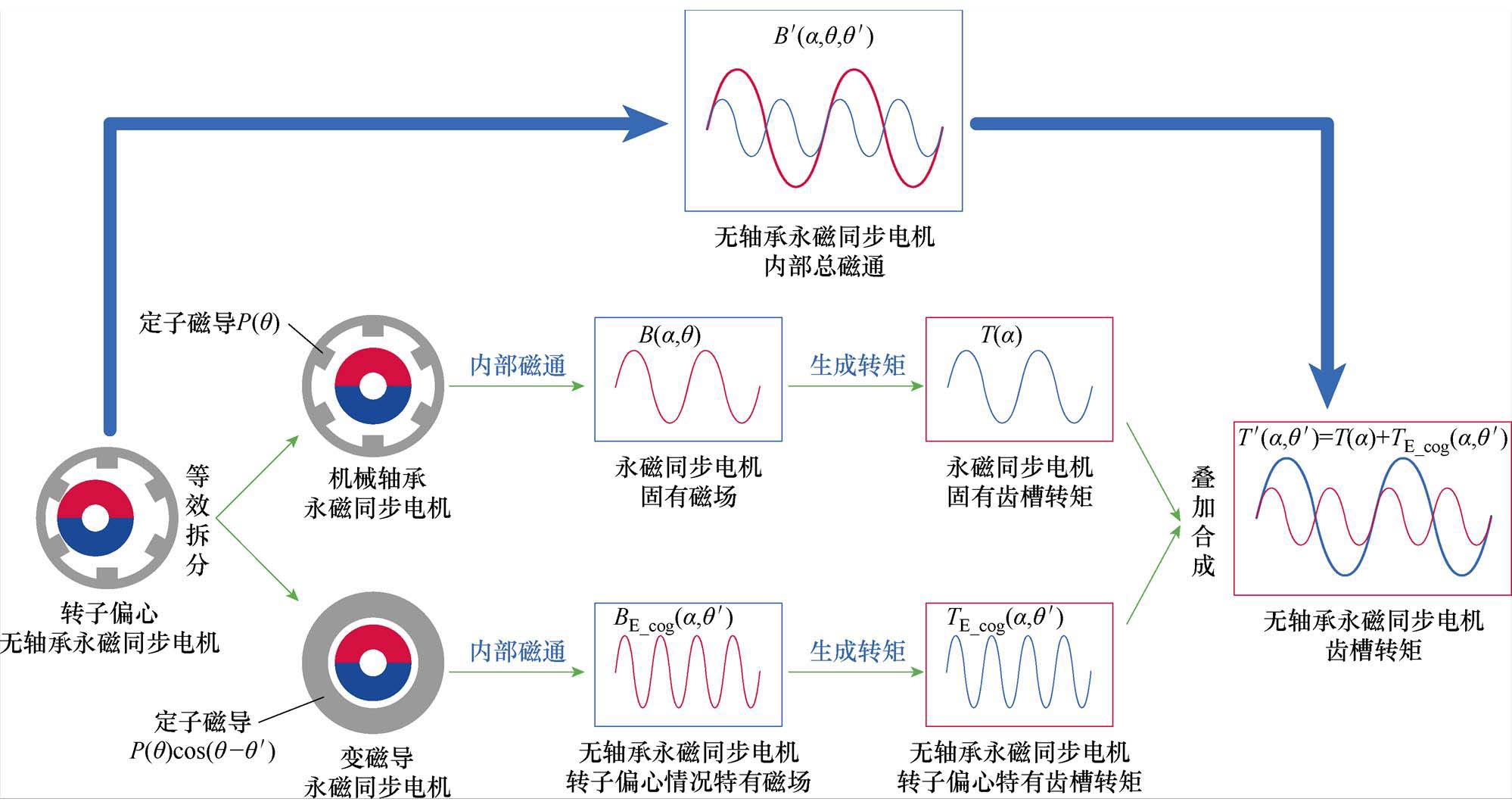
图1 无轴承永磁同步电机齿槽转矩等效叠加示意图
Fig.1 Schematic diagram of equivalent superposition of cogging torque for BLPMSM
摘要 对于应用于高精度场合的无轴承永磁同步电机(BLPMSM),齿槽转矩的存在会对电机运行的稳定性造成严重影响。现有齿槽转矩解析方式多针对机械轴承电机,未考虑无轴承电机中特有的转子偏心情况,因此不适用于无轴承电机。该文提出一种考虑转子偏心的无轴承永磁同步电机分离磁导齿槽转矩解析方式,首先引入气隙畸变函数,分析转子偏心后的气隙变化,对气隙磁导进行重构;然后基于磁路法,将电机磁导分离为两部分,进一步将电机内部磁场和齿槽转矩等效为一台机械轴承永磁同步电机与一台变磁导电机的叠加,并通过仿真验证解析式的正确性;最后基于所提解析式,在控制系统中引入齿槽转矩前馈补偿,并通过仿真和实验验证补偿方式的有效性和优越性。
关键词:无轴承永磁同步电机 齿槽转矩 磁场调制理论 转子偏心 等效气息磁导
随着工业技术的发展,磁悬浮技术与电机相结合,衍生出如无轴承永磁同步电机、无轴承异步电机、无轴承开关磁阻电机等一系列性能不同的无轴承电机。与其他电机相比,无轴承永磁同步电机(Bearing-Less Permanent Magnet Synchronous Motor, BLPMSM)具有高效率、高稳定性、高功率密度、高集成度的优势。因此,无轴承永磁同步电机在超洁净运输、核废料处理等有着高精密度要求的工业场合得到了广泛应用[1],针对电机本体结构和控制性能的研究也受到了广大学者的高度关注。
齿槽转矩是永磁同步电机中的一种固有特性。由于定子铁心开槽引起的电机气隙磁导不均匀,转子在圆周不同位置将受到变化的切向力,即齿槽转矩。齿槽转矩的存在会引起转速脉动。在高速重载的情况下,齿槽转矩的脉动幅值与负载转矩相比较小,因此所引起的转矩脉动可以忽略不计。但是在低速轻载的情况下,转矩脉动过大,严重时甚至会破坏电机运行的稳定性。与传统的有轴承永磁同步电机相比,无轴承永磁同步电机没有了机械轴承的摩擦阻力,使得电机阻尼较小,低速情况下由齿槽转矩引起的转速脉动尤为严重。又因其常应用于高精密度的场合[2-3],急需对转矩脉动进行抑制。
针对永磁同步电机齿槽转矩的解析和脉动抑制技术已经得到了广泛的研究。文献[4]分析了传统永磁同步电机中的设计参数对齿槽转矩的影响,以及极槽配合与齿槽转矩周期的关系,并给出了齿槽转矩的解析公式,但这一公式只适用于有轴承电机中气隙长度不变的情况,无轴承电机转子通常在集合中心附近存在一定的偏心,因此不能用在存在转子偏心不平衡气隙的无轴承电机中。文献[5]结合能量法与磁场调制理论,为齿槽转矩的产生机理提出新的解释,以永磁同步电机为例,给出了其中的齿槽转矩解析公式,并给出了有限元仿真结果;文献[6]则基于气隙磁场重构的方式,分析了3、5、7等低次谐波对齿槽转矩的影响,并提出了永磁体部分磁极反余弦削极技术,对气隙磁场进行重构,抵消低次谐波对齿槽转矩的影响。文献[4-6]均是从减小电机齿槽转矩的角度出发,对转矩脉动进行抑制,可以为无轴承电机中齿槽转矩的解析提供思路。文献[7-12]则是直接考虑转矩脉动的抑制。文献[7]分析了无轴承无刷直流电机中转矩和悬浮力脉动情况,并基于有限元分析,得出了优化后的电机结构,但该研究属于从本体角度减小转矩和悬浮力脉动,考虑到电机结构设计过程中的复杂性,难以做到兼顾抑制脉动和多个电机性能的配合。文献[8]基于高频谐波电流注入和自适应模型预测算法,提出了一种表贴式永磁同步电机转矩脉动抑制的矢量控制算法。文献[9-12]均提出了基于谐波电流注入的方式,以减小电机中的转矩脉动。
由以上研究可以看出,针对永磁同步电机齿槽转矩的补偿方式通常包括电机本体结构优化和控制策略两个方面[13-14]。
在本体设计方面,无轴承永磁同步电机在本体设计时,需要同时兼顾转矩和悬浮力两个方面的性能[15-17],较之传统轴承电机,无轴承电机需要放置转矩和悬浮两套绕组,并且需要安装测量转子位移的传感器,在空间结构的设计上限制较多,无轴承电机的加工过程比一般的电机更为复杂[18-20],因此从电机本体设计的角度出发,只能对齿槽转矩进行有限的抑制[21]。
在控制算法上,为了对齿槽转矩进行补偿,必须得到齿槽转矩的精确解析式[5, 22-25]。在实际运行过程中,无轴承永磁同步电机虽然可以将转子径向位移控制在很小的范围内,转子仍然在几何原点处存在较小的位移波动,处于动态平衡的状态,这是无轴承电机中特有的情况[25-29]。这一微小的位移导致气隙长度发生变化,永磁体转子圆周的气隙磁导也随位移发生相应的变化,这使得原有的有轴承永磁同步电机中齿槽转矩的解析公式不能直接套用到无轴承永磁同步电机中。
为解决无轴承永磁同步电机在转子偏心时的齿槽转矩补偿问题,本文提出一种无轴承永磁同步电机齿槽转矩的解析方式,该方式对偏心后电机内部畸变磁场进行重构,将磁场分为永磁同步电机固有磁场和无轴承电机中由转子偏心引起的特有磁场,从而在分析齿槽转矩时,可将一台无轴承永磁同步电机的内部磁场和齿槽转矩,等效为一台有轴承永磁同步电机与一台“变磁导”永磁同步电机叠加;在提出考虑转子偏心后的齿槽转矩解析公式后,依据解析公式在电机控制算法引入齿槽转矩前馈。最后,由仿真和实验得出结论,验证所提出解析式的正确性和有效性。
永磁转子偏心时,电机不同位置角处气隙长度发生变化,导致定子铁心相对磁导发生畸变。畸变后的磁导可分解为两部分,一部分为机械轴承永磁同步电机所固有的磁导,另一部分为转子偏心引起的偏心磁导,即磁导分离。基于磁导的不同分量,在对电机磁场和齿槽转矩进行解析时,可将其等效为永磁同步电机与“变磁导”电机叠加,如图1所示。
图1 无轴承永磁同步电机齿槽转矩等效叠加示意图
Fig.1 Schematic diagram of equivalent superposition of cogging torque for BLPMSM
由等效磁路法,电机内部磁通密度可视为磁动势与磁导的乘积。在转子不偏心情况下,沿气隙圆周角 展开,永磁体磁动势FPM和磁导P傅里叶展开形式[30]为
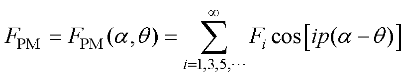 (1)
(1)
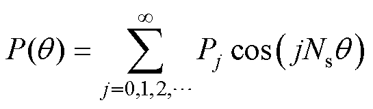 (2)
(2)
式中,Fi为磁动势i次谐波幅值;Pj为磁导j次谐波幅值;i为正奇数;j为正整数;p为永磁体极对数;Ns为定子齿数; 为转子位置角。式(1)和式(2)的解析公式均为不偏心情况下的磁动势与磁导解析,当转子偏心时,磁动势与磁导直接的相互作用发生变化,电机内部磁场解析不能直接由原先的磁动势和磁导相乘得到,需要对偏心时的磁动势和磁导解析式进行重构。
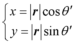
以电机中心点作为原点,构建二维直角坐标系。当转子偏心时,可以视作转子在电机几何中心原点处发生了一个位移,如图2所示。图中, 为偏心角度,x和y分别为x方向和y方向的位移。
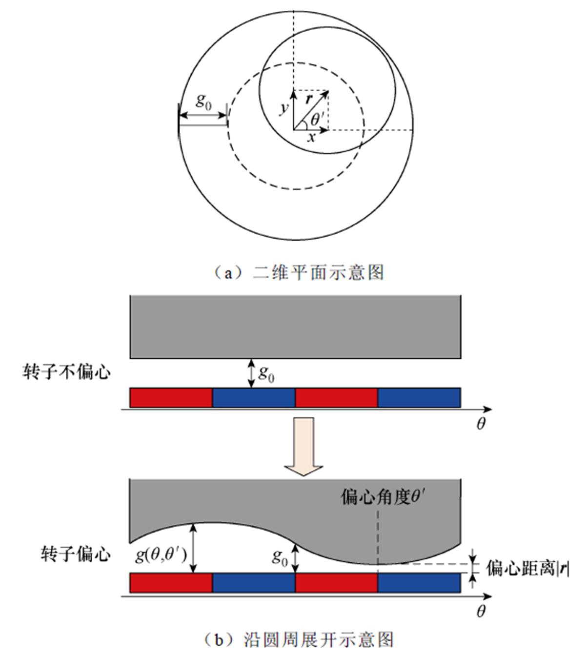
图2 转子偏心示意图
Fig.2 Schematic diagram of rotor eccentricity
图2a中, 为转子偏心位移向量,包含了大小和方向两个物理量,
 为偏心位移大小。
 为电机气隙长度函数,该函数是由气隙圆周角和偏心角度所构成的二元函数。
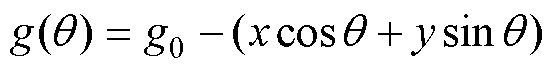
文献[31]给出了偏心情况下,气隙长度沿转子圆周角的分布函数 为
为
 (3)
(3)
其中
 (4)
(4)
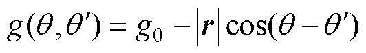
式中,g0为不偏心时气隙长度。
因此,代入式(3)可得偏心后气隙分布函数为
 (5)
(5)
偏心后的磁导分布函数为
 (6)
(6)
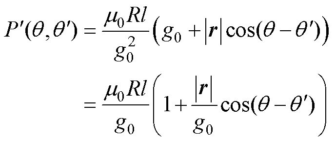
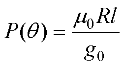
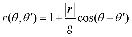
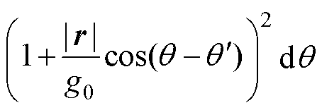
式中,R为转子外半径;l为电机轴向长度; 为真空磁导率。又有不偏心情况下的磁导[18]为
 (7)
(7)
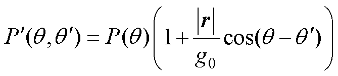
因此,式(6)可改写为
 (8)
(8)
可见在转子偏心情况下,气隙磁导发生了畸变,定义式(8)的后一项为畸变函数 ,有
,有
 (9)
(9)
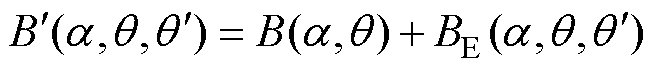
由此,可构建转子偏心情况下,电机内部磁通密度分布函数 为
为
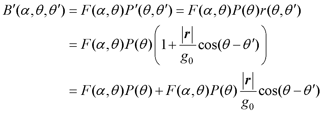 (10)
(10)
式中,前后两项磁场只有磁导不同,故将其分离。前一项为永磁同步电机固有磁通密度 ,可视为由一台有轴承且转子不偏心的永磁同步电机产生;后一项为转子偏心所引起偏心特有磁通,由于其磁导是随着偏心位移和角度而变化的函数,故可视为一台磁导变化的永磁同步电机所产生的磁通,定义其为
 ,则有
,则有
 (11)
(11)
 (12)
(12)
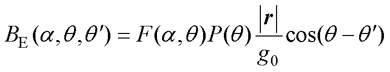
可以看出,偏心后的磁通密度可以视为由一台有轴承永磁同步电机与一台变磁导电机叠加而成。将式(1)和式(2)代入(12),可得的BE详细表达式为
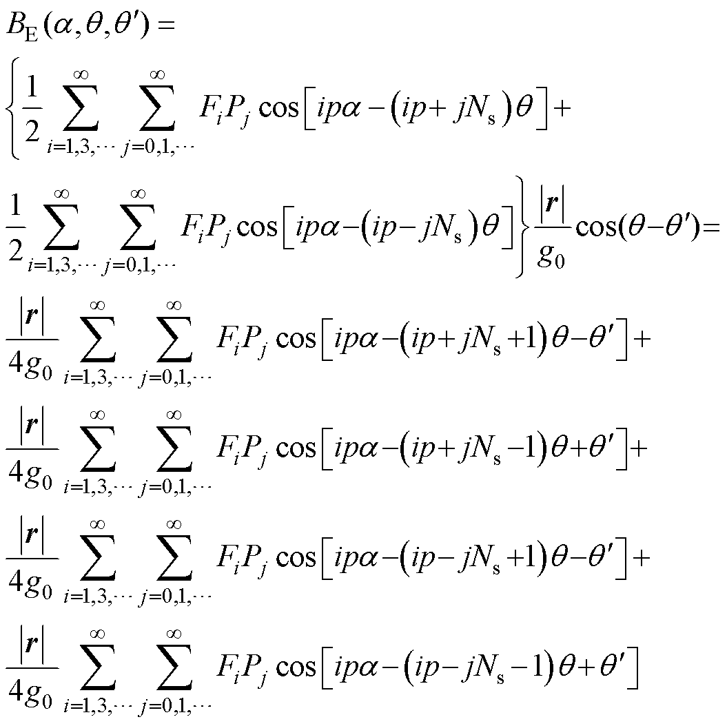 (13)
(13)
由磁场调制理论可知[17],机械轴承永磁同步电机的磁通密度包含了极对数为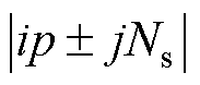 的磁通;而变磁导电机磁通BE包含四种谐波磁通,其极对数为
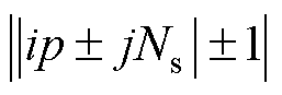 。转子偏心的引入,使得气隙中出现了与原有气隙磁场谐波极对数相差±1次的谐波。
偏心情况下电机内部磁场各分量极对数及其转速见表1。
表1 偏心情况下电机磁场分量
Tab.1 Components of magnetic field with eccentric rotor
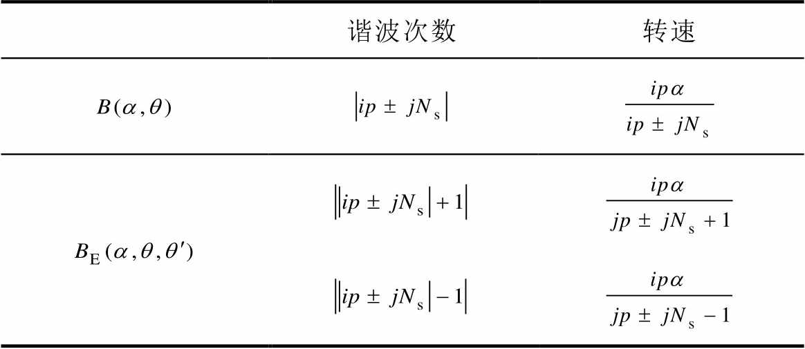
谐波次数转速
第1节已经推导出偏心情况下的电机内部磁通密度分布,本节将对偏心情况下电机齿槽转矩解析进行推导。
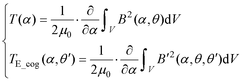
在永磁同步电机中,齿槽转矩是由定子开槽引起的气隙磁导不均匀而导致的特有属性,即使在电枢绕组电流为零的情况下,这一属性也依然存在。因此,可以在空载情况下对齿槽转矩进行解析。电机空载时,齿槽转矩即为永磁体与电机铁心相互作用产生的转矩[32],基于能量法,可视为电机内部磁共能对转子位置角的导数[5],即
 (14)
(14)
式中,W为磁共能。为方便后续分析,现做如下假设:不考虑铁心饱和且磁导无穷大;永磁体相对磁导率与空气磁导率一致。在空载时,电机内部磁场能量几乎完全储存在气隙和永磁体中。因此,电机内部磁共能[5]可表示为

 (15)
(15)
式中,Wmag为永磁体内储存的磁场能量;Wair为气隙中的磁场能量;B为气隙磁通密度;V为体积。
将式(12)代入式(14)和式(15),可以得出偏心情况下,齿槽转矩解析式为
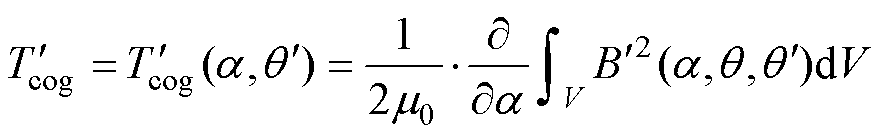 (16)
(16)
将体积分沿圆周展开得
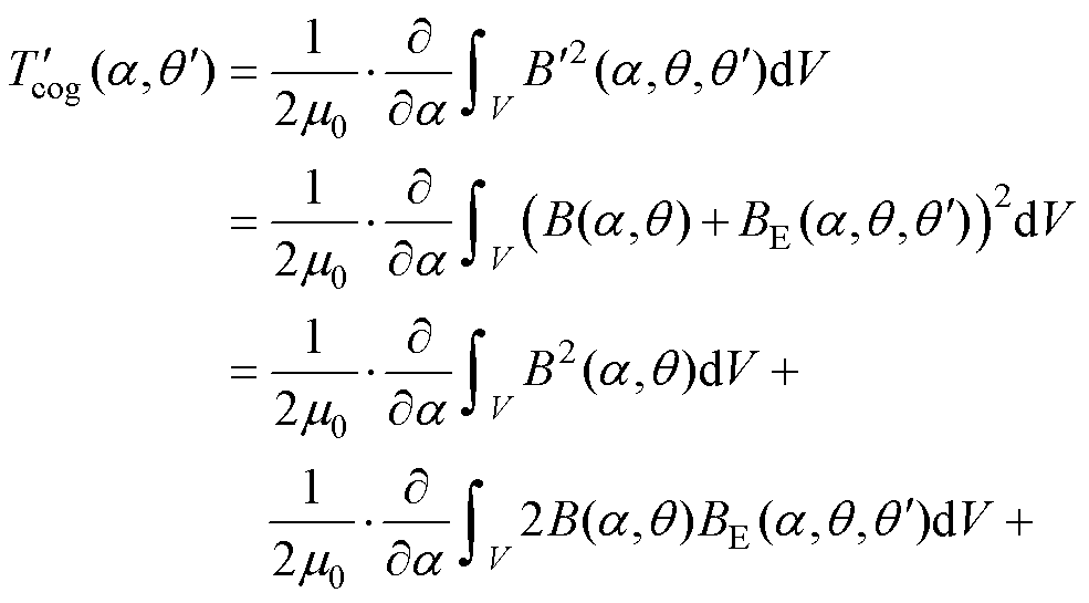
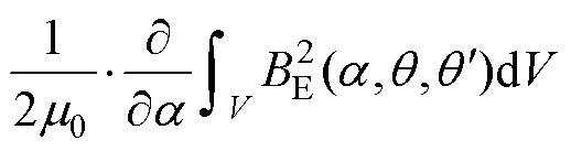 (17)
(17)
式(17)中,偏心情况下的齿槽转矩由三项相加而成。第一项为不偏心情况下的齿槽转矩 ,由永磁同步电机固有磁通密度产生,为永磁同步电机中固有的齿槽转矩;中间项中,和极对数相差±1,由三角函数正交性可知,二者相乘后的积分为0,故不产生转矩;最后一项可视为变磁导电机的磁通所产生的齿槽转矩分量,定义其为
 ,由偏心特有磁通产生。则偏心情况下的齿槽转矩同样可以看作由两种电机的齿槽转矩分量叠加而成,有
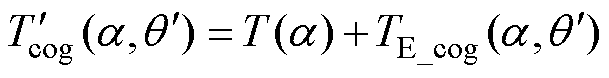 (18)
(18)
 (19)
(19)
由上述分析,依据偏心情况下磁导的不同分量,将电机内部磁通和齿槽转矩进行分离。转子偏心情况下,无轴承永磁同步电机的内部磁通可等效为一台有轴承的永磁同步电机与一台变磁导永磁同步电机两种分量叠加而成,这两种分量分别产生齿槽转矩,两种转矩分量叠加后,即为无轴承永磁同步电机齿槽转矩。将式(13)中磁场解析式代入式(19)可得齿槽转矩详细解析式为
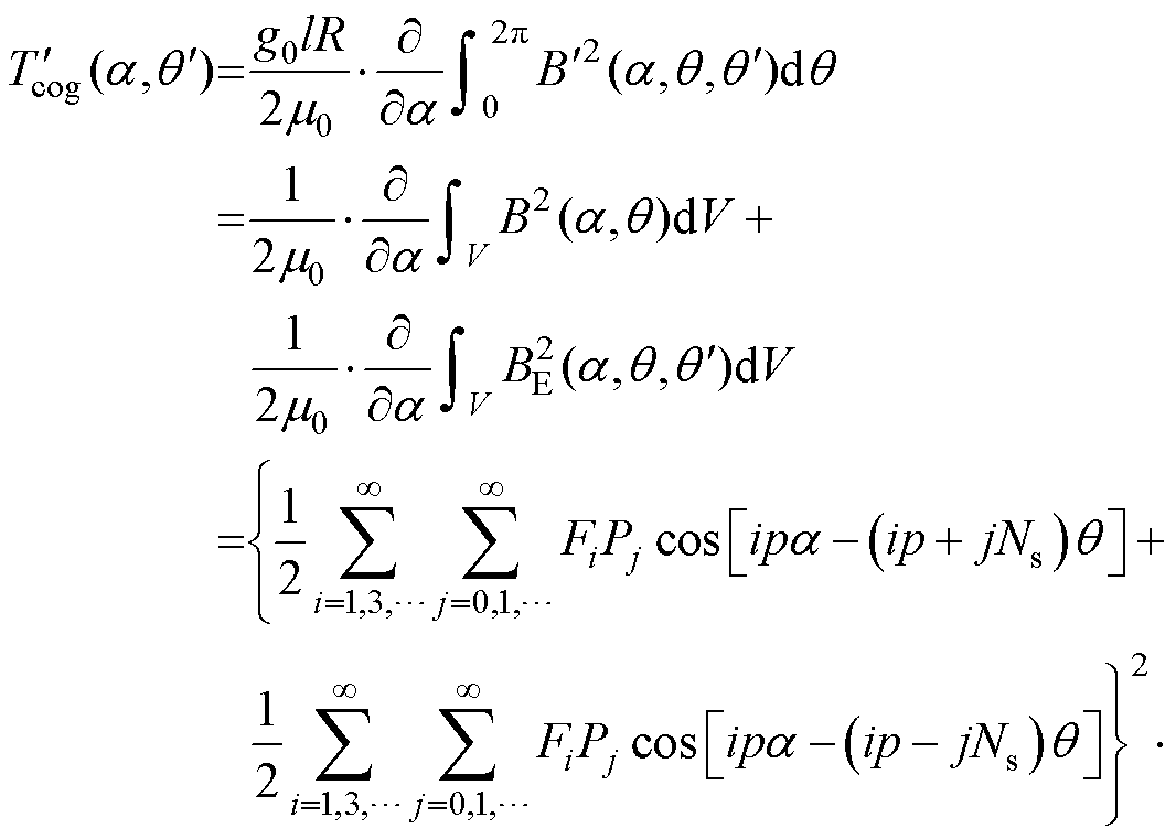
 (20)
(20)
式中,转子圆周角在积分之后不再充当未知数,因此,齿槽转矩是关于转子转角和偏心角度 的二元函数。需要注意的是,当式(20)中,
 =0,=0时,即为不偏心情况下齿槽转矩解析式。至此,等效磁路法的无轴承永磁同步电机分离磁导齿槽转矩解析方式推导完毕。
为验证所构建无轴承永磁同步电机齿槽转矩解析式的准确性,以一台分数槽薄片电机为例,进行有限元仿真验证。所构建电机模型中,定子齿数为6,绕组结构为分数槽短距绕组,转子为一对极环形永磁体,初始偏心角度为=180°,偏心位移长度=1.5 mm。所构建电机模型具体参数见表2,电机拓扑如图3所示。
表2 BLPMSM参数
Tab.2 Parameters of BLPMSM
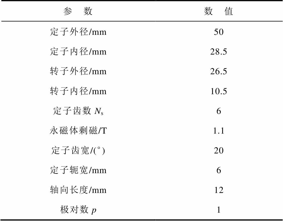
参 数数 值 定子外径/mm50 定子内径/mm28.5 转子外径/mm26.5 转子内径/mm10.5 定子齿数Ns6 永磁体剩磁/T1.1 定子齿宽/(°)20 定子轭宽/mm6 轴向长度/mm12 极对数p1
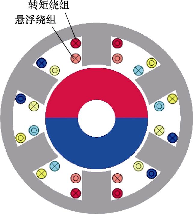
图3 电机拓扑
Fig.3 Motor topology
由第2节分析可知,转子偏心情况下的无轴承永磁同步电机,其内部磁场和齿槽转矩可视为由一台有轴承电机与变磁导电机叠加而成。有限元仿真可得永磁同步电机和无轴承电机中的磁通与齿槽转矩,变磁导电机中数据由计算得出,磁通叠加与拟合情况结果如图4所示。
图4a展示了第1节所提出的永磁同步电机磁通与变磁导电机磁通叠加拟合而成的无轴承电机磁通,拟合结果与仿真结果的对比如图4b所示。拟合结果与有限元仿真对比的平均绝对误差为0.002 63 T,差值方均根为0.003 92 T,拟合结果与仿真结果的误差在可接受范围内。
图5展示了第2节所提出的无轴承永磁同步电机齿槽转矩拟合结果与有限元仿真结果对比,结果显示所提的齿槽转矩解析式能够较为精准地解算出齿槽转矩。图5a展示了所提出分离磁导拟合方式,图5b验证了其正确性,图5c展示了本文的解析方法在转子不偏心情况下拟合情况与有限元仿真对比。
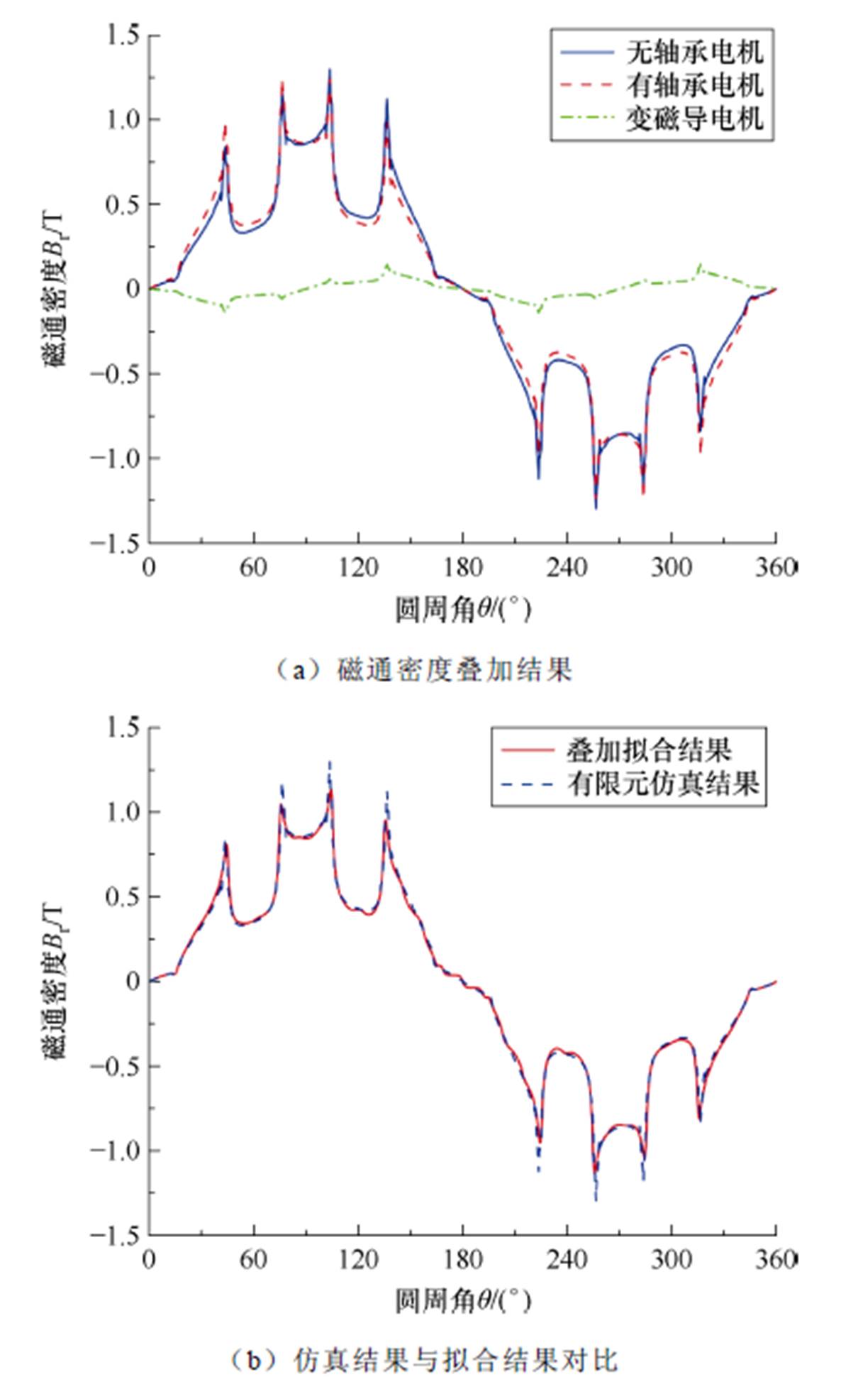
图4 磁通密度叠加与拟合情况结果
Fig.4 Magnetic flux superposition result
基于第2节所提出的无轴承永磁同步电机齿槽转矩解析式,在电机控制系统中引入前馈,从而抵消电机的齿槽转矩,减小转速脉动。在Simulink中搭建控制系统仿真模型,以验证所提算法的可行性。控制系统大致框图如图6所示,图中,Kcog为齿槽转矩补偿系数,补偿前后效果对比如图7所示。
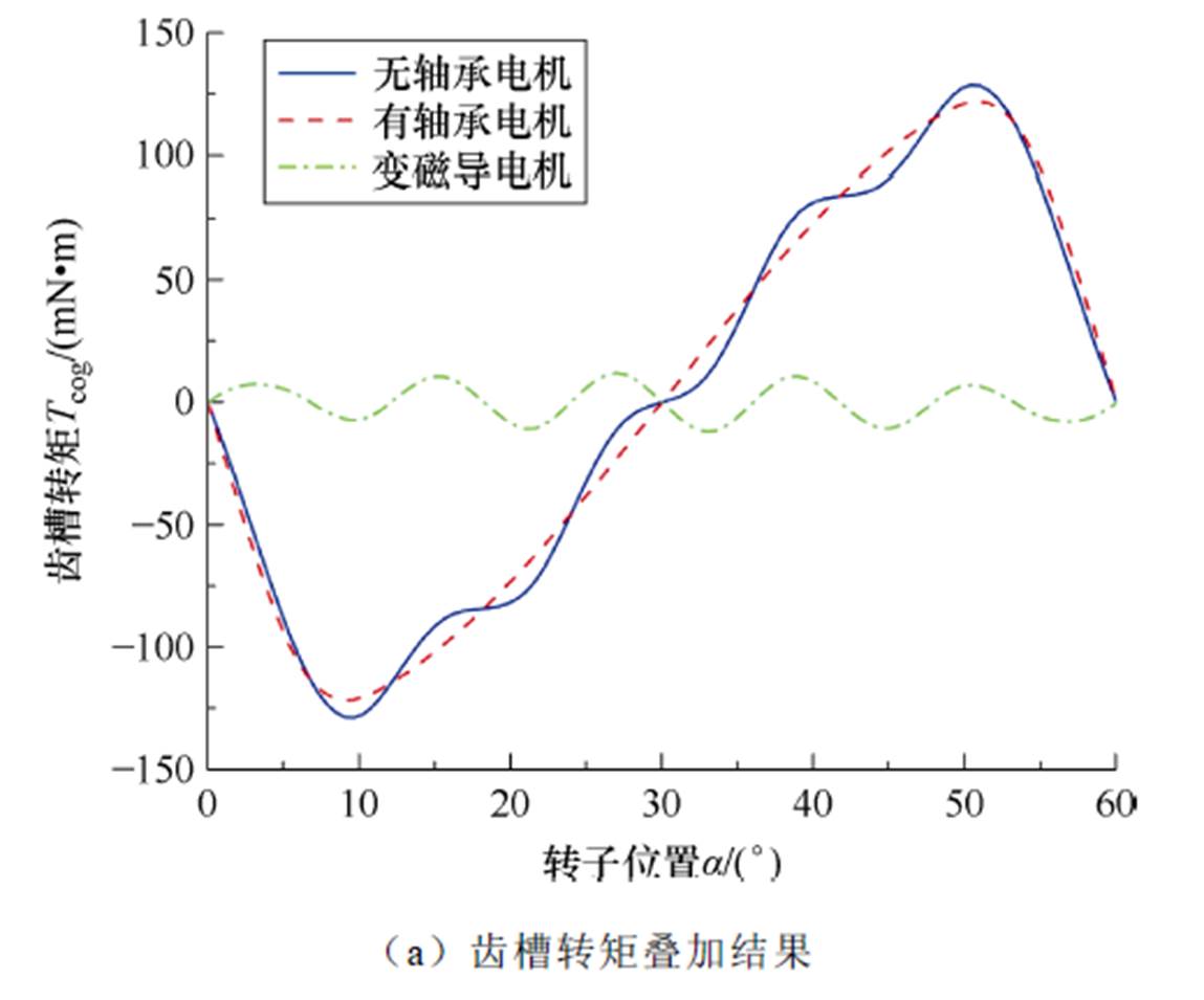
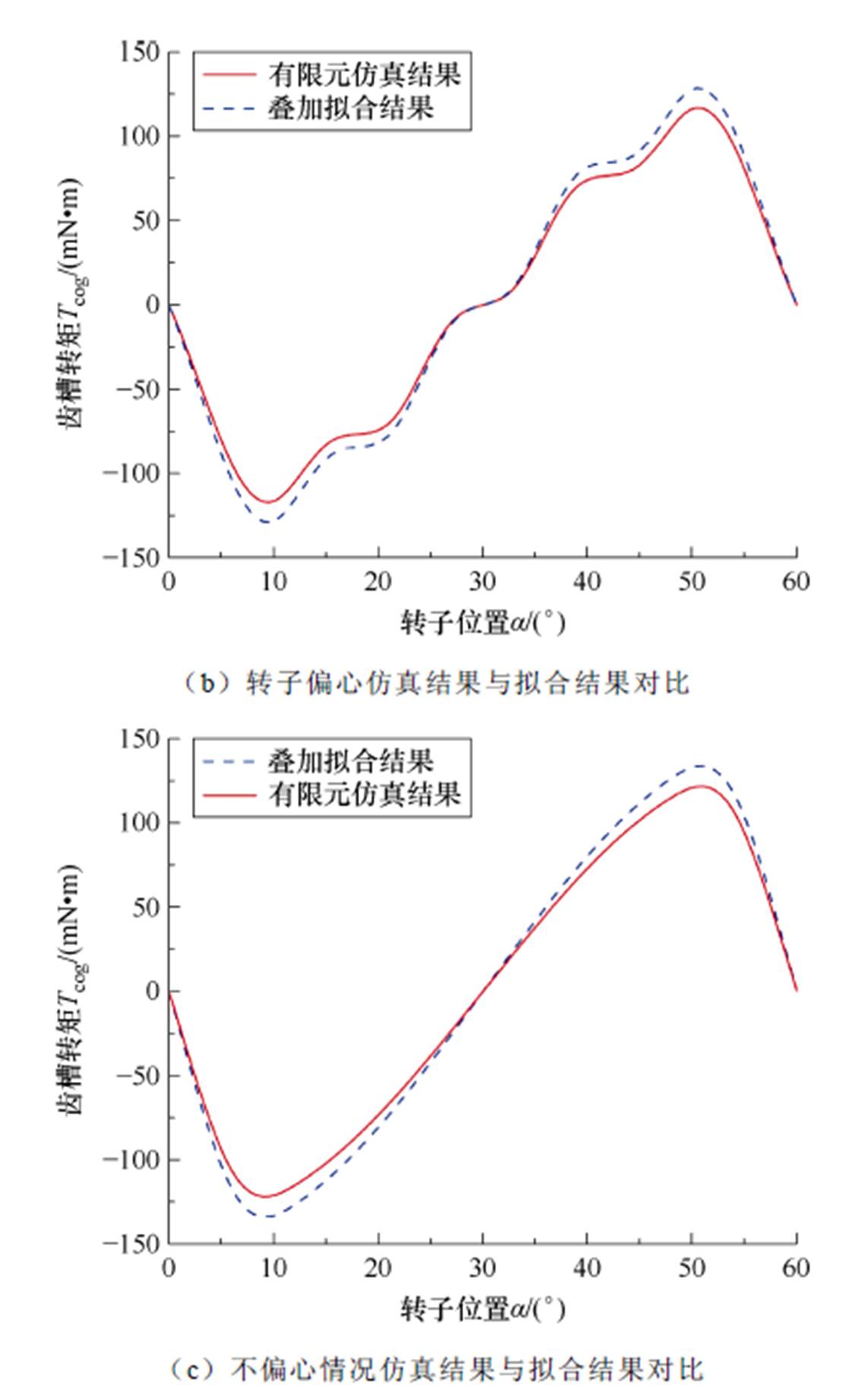
图5 转矩拟合结果
Fig.5 Torque superposition result
由仿真可以看出,本文所提出的无轴承永磁同步电机齿槽转矩解析式精度较高,基于此解析式所构建的补偿算法可有效抑制由齿槽转矩引起的转速脉动,使得电机平稳运行。
为验证本文所提出的考虑转子偏心的无轴承永磁同步电机齿槽转矩解析式,以及基于此所提出的转矩补偿算法的正确性,实验室搭建了如图8所示的实验平台,包括无轴承薄片电机、基于DSP28335的控制系统等。控制器参数见表3。
本实验平台的无轴承永磁同步电机,利用霍尔元件同时检测转子转角和转子位移信号。其中霍尔元件对磁场信号进行负序解耦,解析出位移信号。电机定子铁心上缠绕有两组绕组,分别控制电机的转矩和悬浮力,即“转矩绕组”和“悬浮绕组”;电流信号由电阻采样的方式采集三相电流信号,实现电流闭环。
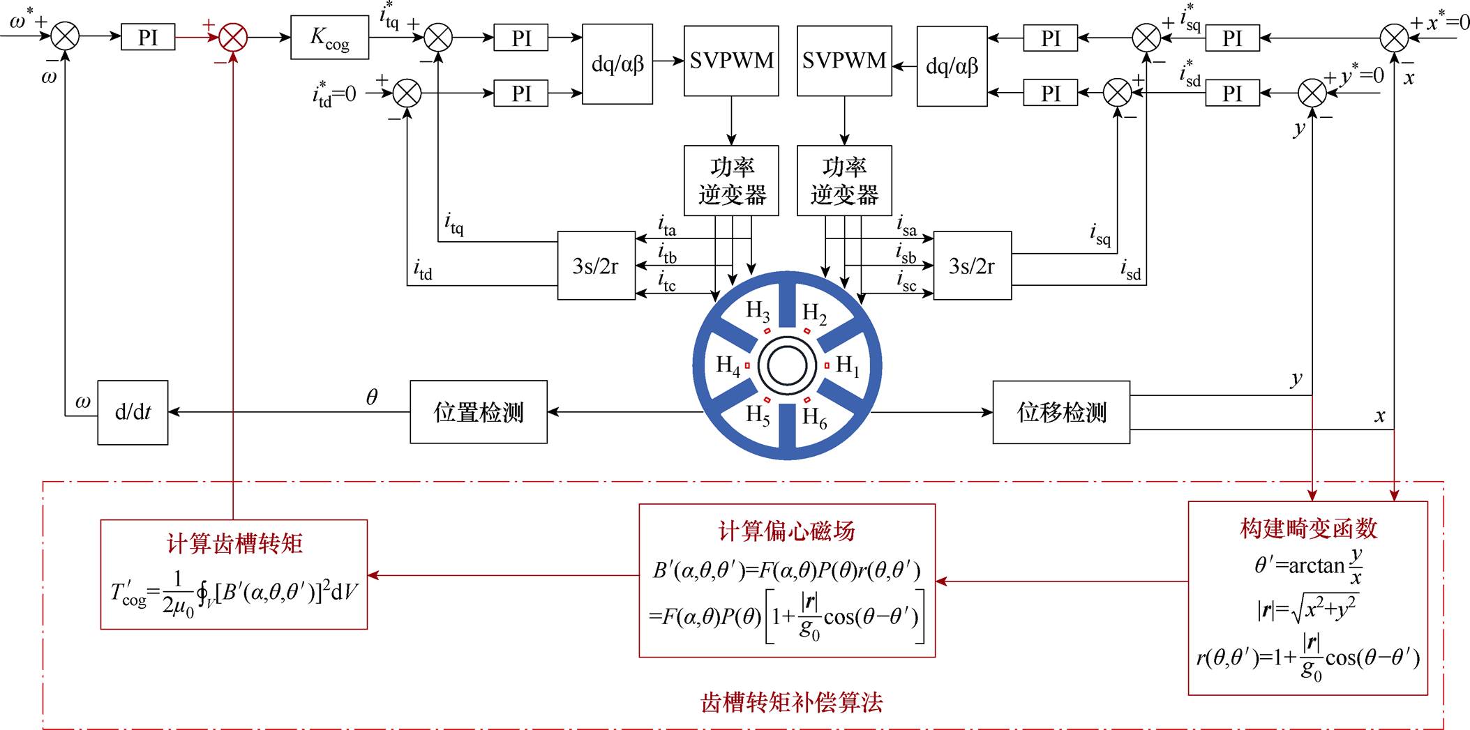
图6 控制系统框图
Fig.6 Block diagram of control system
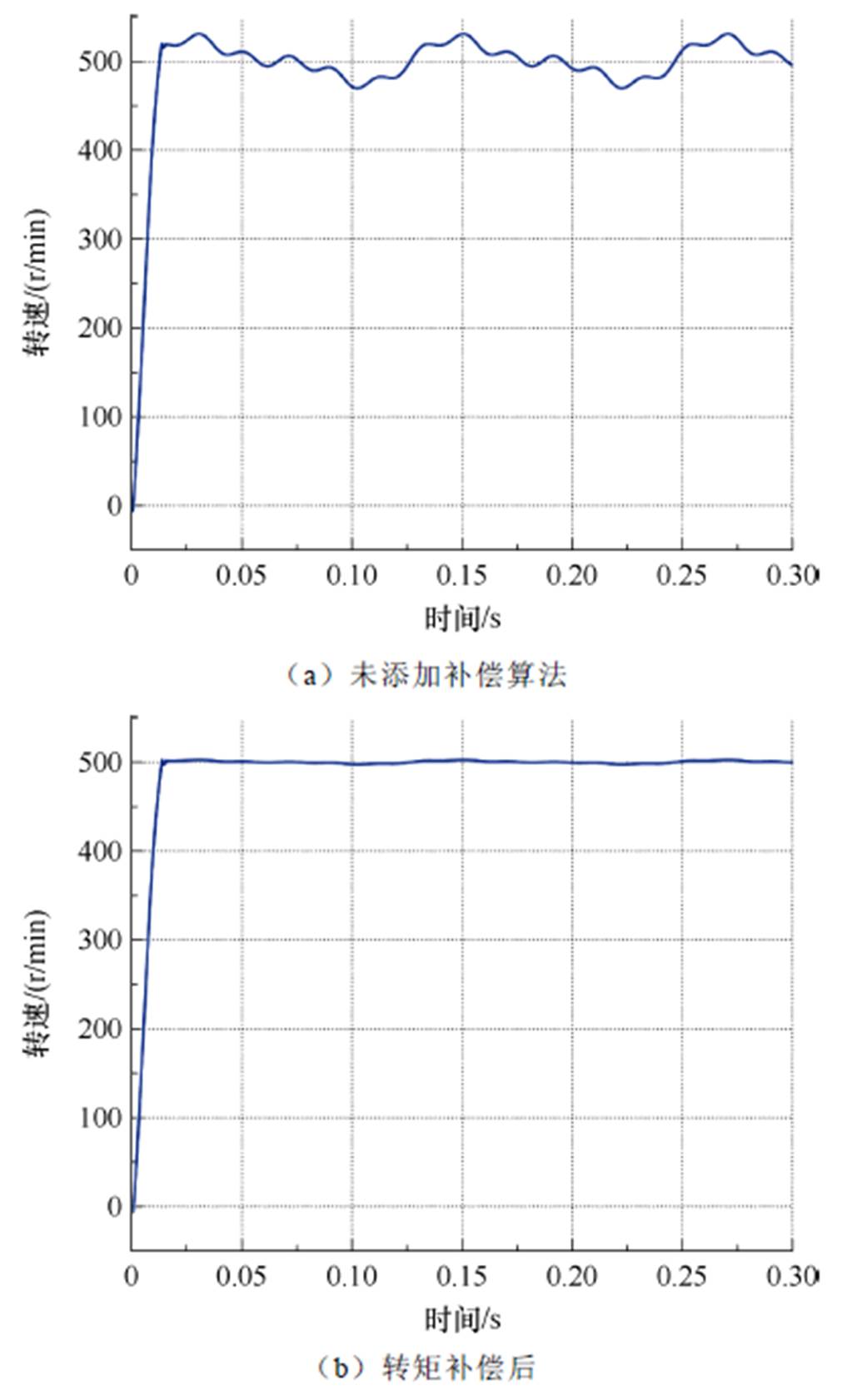
图7 齿槽转矩补偿算法效果对比
Fig.7 Comparison of the effectiveness of cogging torque compensation algorithms
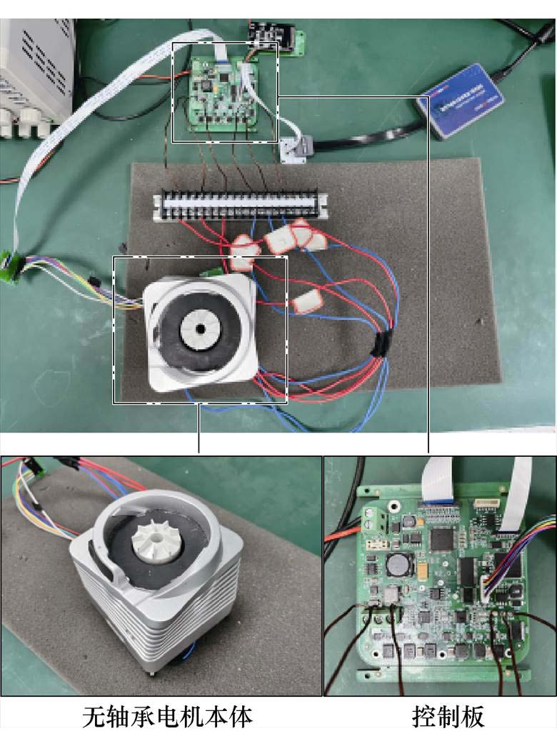
图8 实验平台
Fig.8 Experimental platform
电机参数见表4。电机本身的数学模型在控制系统中可等效视作低通滤波器,随着转速升高,滤波效果越来越明显,因此齿槽转矩在低速情况下造成的影响更大。分别在低速500 r/min、1 000 r/min转速情况下进行了齿槽转矩补偿实验。500 r/min和1 000 r/min补偿前转速脉动情况以及对转速的傅里叶分解结果分别如图9和图10所示。
表3 控制器参数
Tab.3 Parameters of controller
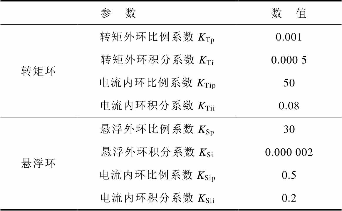
参 数数 值 转矩环转矩外环比例系数KTp0.001 转矩外环积分系数KTi0.000 5 电流内环比例系数KTip50 电流内环积分系数KTii0.08 悬浮环悬浮外环比例系数KSp30 悬浮外环积分系数KSi0.000 002 电流内环比例系数KSip0.5 电流内环积分系数KSii0.2
表4 电机参数
Tab.4 Parameters of motor
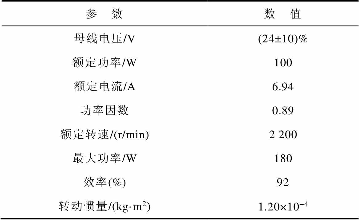
参 数数 值 母线电压/V(24±10)% 额定功率/W100 额定电流/A6.94 功率因数0.89 额定转速/(r/min)2 200 最大功率/W180 效率(%)92 转动惯量/(kg·m2)1.20×10-4
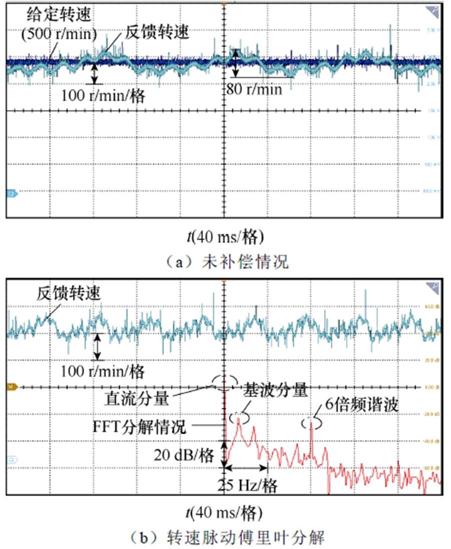
图9 转速500 r/min转速脉动分析
Fig.9 Analysis of speed pulsation compensation with speed of 500 r/min
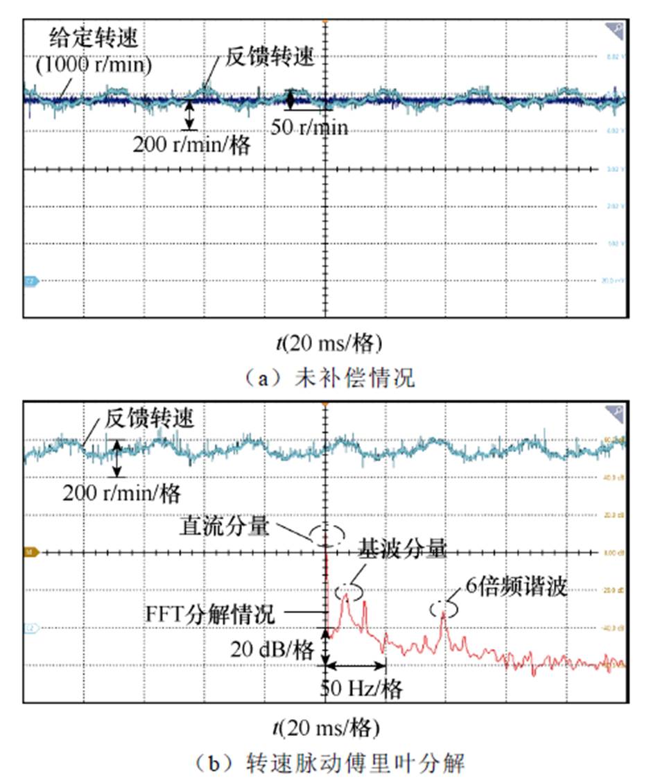
图10 转速1 000 r/min转速脉动分析
Fig.10 Analysis of speed pulsation compensation with speed of 1 000 r/min
由实验可以看出,补偿前,500 r/min时齿槽转矩引起的转速脉动大约为80 r/min,1 000 r/min时则为50 r/min左右。对转速脉动进行傅里叶分解,其中幅值较高的脉动谐波为一倍频和六倍频谐波,六倍频为实验所采用六齿一对极永磁同步电机所固有的齿槽转矩脉动频率,一倍频脉动是由于偏心角度 变化速度与转子位置角相同,因此引起一倍频转速脉动。
依据第2节提出的齿槽转矩解析式,在控制系统中引入转矩前馈补偿,以减小转速脉动。由于引入了前馈,系统给定转矩叠加了高频的齿槽转矩解析值,从而在给定电流中注入了高频谐波。500 r/min和1 000 r/min转速下,电机A相电流以及转速补偿情况分别如图11和图12所示。
由实验可以看出,在引入齿槽转矩前馈后,电机相电流中注入了高次谐波,这是由于齿槽转矩谐波通常较高,需要引入高频谐波以抵消齿槽转矩脉动。采用补偿算法后,对转速进行傅里叶分解,其结果如图13所示。由图13可以看出,补偿后的转速,其高次谐波分量得到了有效的抑制和消除。
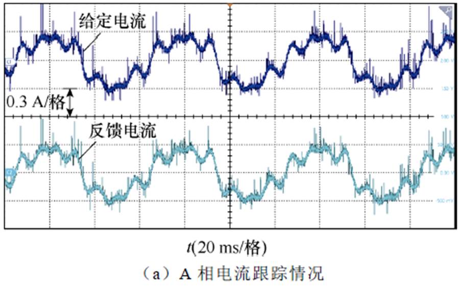
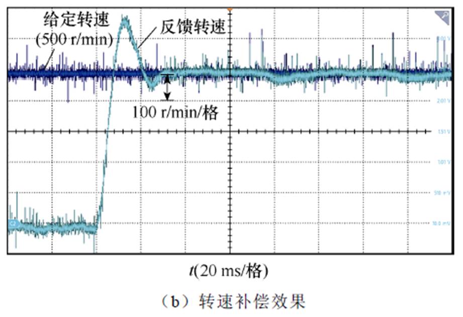
图11 转速500 r/min时A相电流及转速补偿效果
Fig.11 Phase A current and speed compensation effect at a speed of 500 r/min
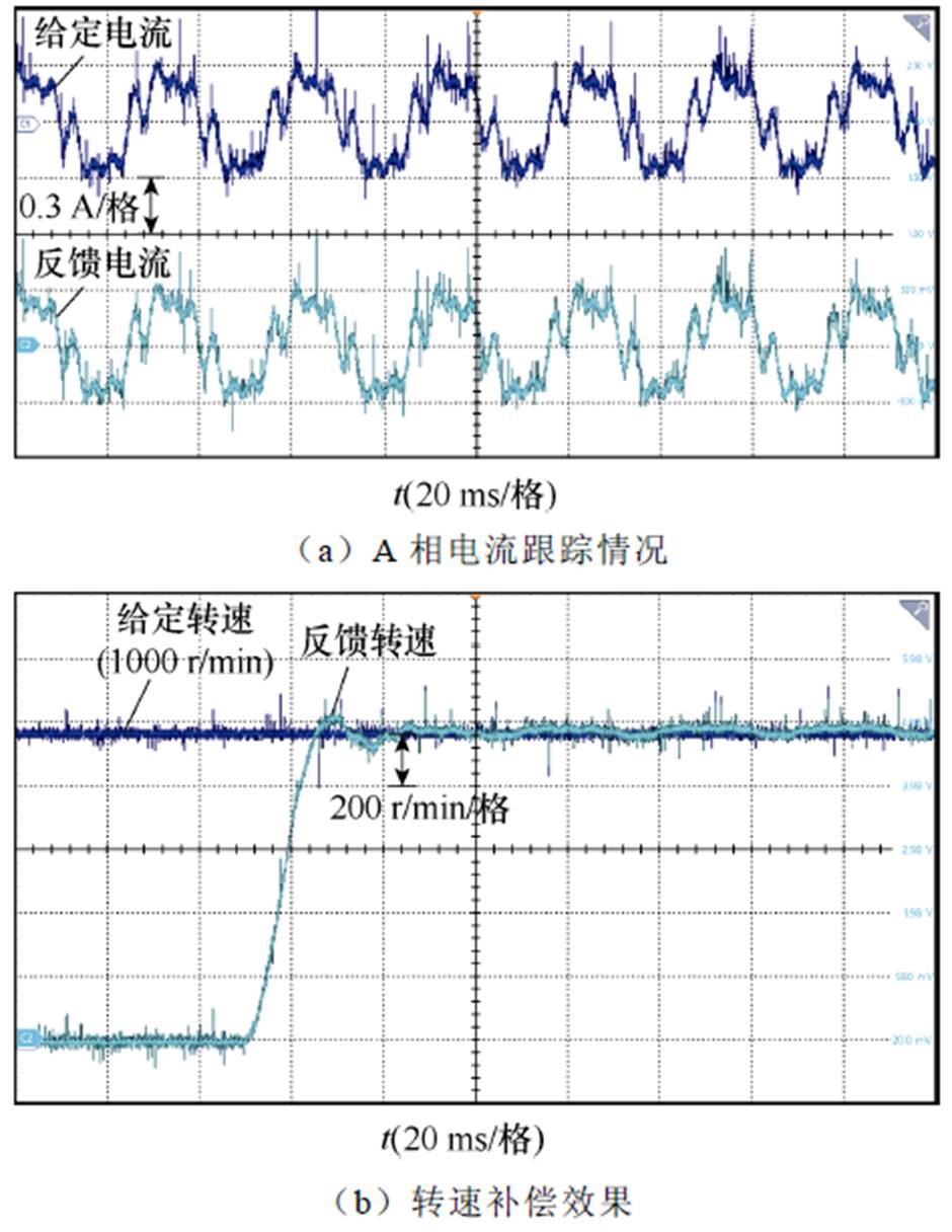
图12 转速1 000 r/min时A相电流及转速补偿效果
Fig.12 Phase A current and speed compensation effect at a speed of 1 000 r/min
在1 500 r/min和2 000 r/min转速情况下,随着转速的升高,齿槽转矩影响效果稍有减小,但仍然存在。采用基于本文所提出的前馈补偿方法,可有效减少转速脉动,结果如图14和图15所示。同时,为对比本文的解析模型与现有的未考虑转子偏心模型的补偿效果,在1 500 r/min和2 000 r/min下进行了对比,如图14c和图15c所示,可以体现本文模型一定的优越性。可见,现有的不考虑转子偏心的补偿,可以消除一部分高频的转速脉动,但低频的脉动无法消除,而这一部分脉动恰好是由转子偏心引起的。
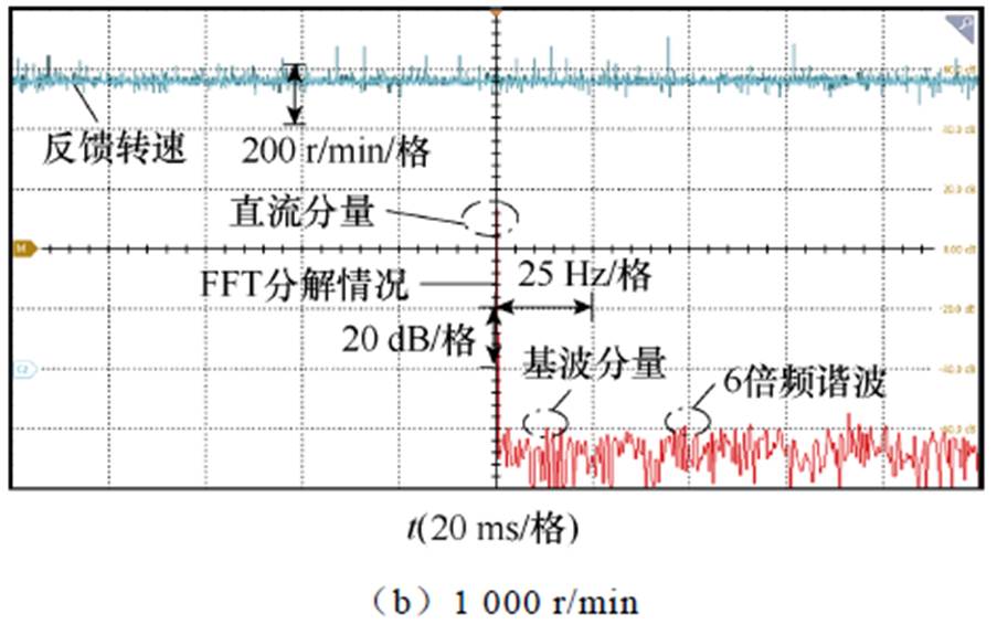
图13 补偿后转速傅里叶分解
Fig.13 FFT of speed after compensation
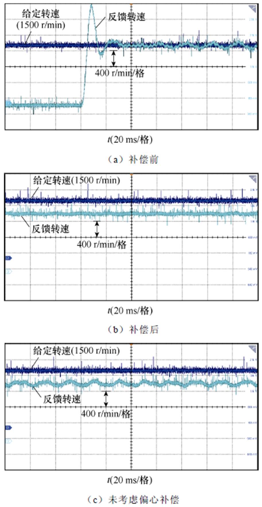
图14 1 500 r/min下补偿前后转速
Fig.14 1 500 r/min before and after compensation
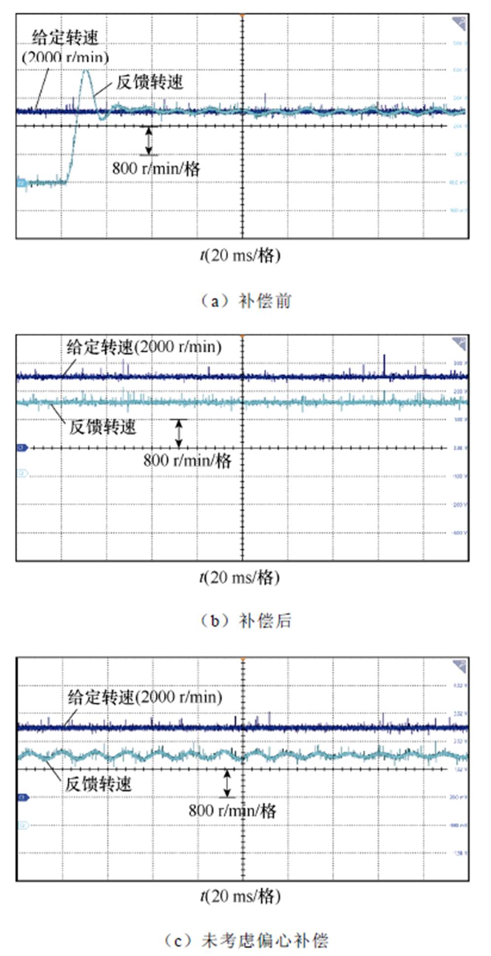
图15 2 000 r/min下补偿前后转速
Fig.15 2 000 r/min before and after compensation
在低速50 r/min和100 r/min转速下,同样对齿槽转矩进行补偿,实验结果如图16和图17所示。
转速脉动以及各次谐波的抑制效果如图18所示。500 r/min下,1次谐波脉动可抑制70%,6次谐波脉动可抑制90%,总转速脉动可抑制82%;1 000 r/min下,1次谐波脉动可抑制75%,6次谐波脉动可抑制87%,总转速脉动可抑制80%。
由实验可以看出,基于本文所提出的齿槽转矩解析式,可对电机转速波动进行有效抑制,证明了本文所提出的解析方法精度较高,电机运行的稳定性得到了显著提高。
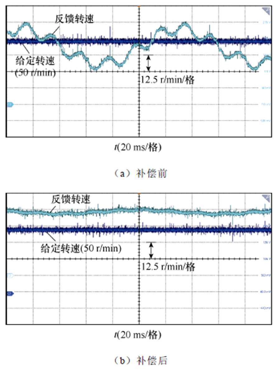
图16 50 r/min下补偿前后转速
Fig.16 50 r/min before and after compensation
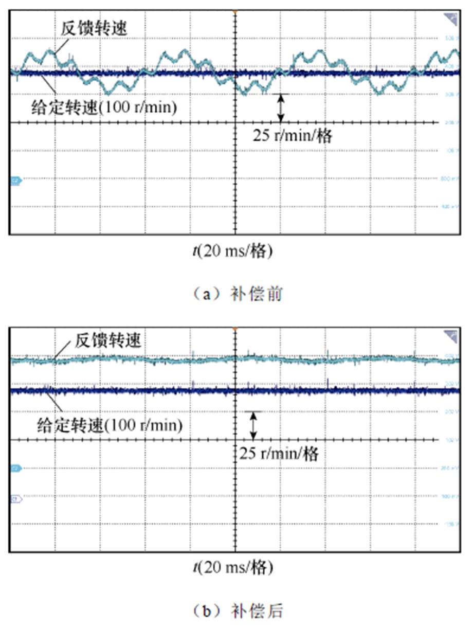
图17 100 r/min下补偿前后转速
Fig.17 100 r/min before and after compensation
本文针对无轴承永磁同步电机中特有的转子偏心情况及其齿槽转矩,在对偏心后的电机内部磁场进行重构后,提出了一种分离磁导的齿槽转矩解析方式。结论如下:
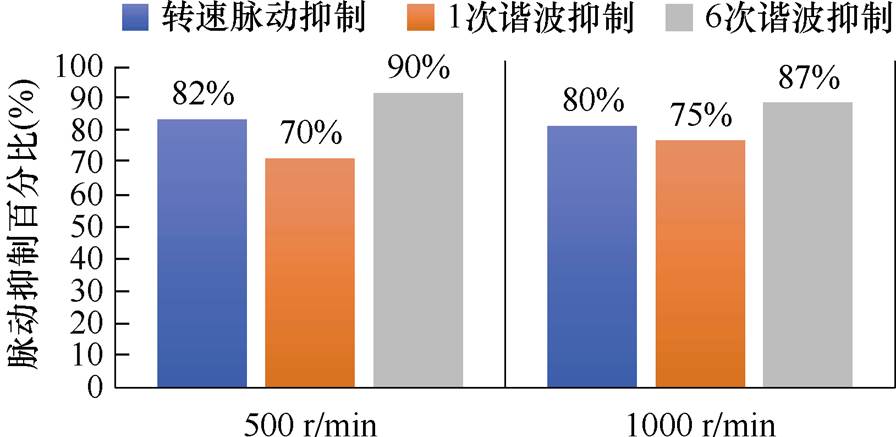
图18 补偿效果对比
Fig.18 Comparison of compensation effect
1)在转子偏心情况下,可将无轴承永磁同步电机内部磁场视为机械轴承电机与“变磁导”电机叠加而成,所解析的偏心畸变磁场精度较高,磁通拟合精度在98%以上。
2)基于所构建偏心磁通解析式,对无轴承永磁同步电机齿槽转矩进行解析,其解析结果与有限元仿真结果重合度较高,误差在3%以内。
基于所提出齿槽转矩解析式,在控制系统中引入齿槽转矩前馈,以消除转矩脉动。所提出解析式可有效抑制齿槽转矩所引起的转速脉动。500 r/min和1 000 r/min转速下可抑制80%以上的转速脉动,傅里叶分解结果显示,对齿槽转矩引起的转速脉动高频谐波,抑制效果达70%以上。
参考文献
[1] Neff M, Barletta N, SCHOEB R. Bearingless- centrifugal pump for highly pure chemicals[C]//8th International Symposium on Magnetic Bearing, Mito, Japan, 2002: 283-288.
[2] Ronco C, Navalesi P, Vincent J L. Coronavirus epidemic: preparing for extracorporeal organ support in intensive care[J]. The Lancet Respiratory Medicine, 2020, 8(3): 240-241.
[3] 刘鑫, 曲洪一, 王聪, 等. 第3代人工心脏泵研究进展及应用[J]. 中国生物医学工程学报, 2022, 41(3): 339-350.
Liu Xin, Qu Hongyi, Wang Cong, et al. Research progress and application of the third generation of artificial heart pump[J]. Chinese Journal of Bio- medical Engineering, 2022, 41(3): 339-350.
[4] Zhu Z Q, Howe D. Influence of design parameters on cogging torque in permanent magnet machines[C]// 1997 IEEE International Electric Machines and Drives Conference Record, Milwaukee, WI, USA, 1997: MA1/3.1-MA1/3.3.
[5] 刘家琦, 白金刚, 郑萍, 等. 基于磁场调制原理的齿槽转矩研究[J]. 电工技术学报, 2020, 35(5): 931-941.
Liu Jiaqi, Bai Jingang, Zheng Ping, et al. Investi- gation of cogging torque based on magnetic field modulation principle[J]. Transactions of China Elec- trotechnical Society, 2020, 35(5): 931-941.
[6] 王凯, 孙海阳, 朱姝姝, 等. 基于气隙磁场重构的永磁电机转矩脉动抑制研究[J]. 中国电机工程学报, 2023, 43(7): 2563-2572.
Wang Kai, Sun Haiyang, Zhu Shushu, et al. Airgap magnetic field reconstruction for torque ripple mitigation of permanent magnet machines[J]. Pro- ceedings of the CSEE, 2023, 43(7): 2563-2572.
[7] Qiu Zhijian, Chen Wangwei, Ma Dongxu, et al. Analysis of torque and suspension force fluctuation of a bearingless brushless DC motor based on cogging boundary condition[C]//2020 8th International Con- ference on Control, Mechatronics and Automation (ICCMA), Moscow, Russia, 2020: 167-171.
[8] Zhang Peng, Sizov G Y, Demerdash N A O. Com- parison of torque ripple minimization control tech- niques in surface-mounted permanent magnet syn- chronous machines[C]//2011 IEEE International Electric Machines & Drives Conference (IEMDC), Niagara Falls, ON, Canada, 2011: 188-193.
[9] Hanselman D C. Minimum torque ripple, maximum efficiency excitation of brushless permanent magnet motors[J]. IEEE Transactions on Industrial Elec- tronics, 1994, 41(3): 292-300.
[10] N’Diaye A, Espanet C, Miraoui A. Reduction of the torque ripples in brushless PM motors by optimization of the supply-theoretical method and experimental implementation[C]//2004 IEEE International Sympo- sium on Industrial Electronics, Ajaccio, France, 2004: 1345-1350.
[11] Hung J Y, Ding Z. Design of currents to reduce torque ripple in brushless permanent magnet motors[J]. IEE Proceedings B Electric Power Applications, 1993, 140(4): 260.
[12] Le-Huy H, Perret R, Feuillet R. Minimization of torque ripple in brushless DC motor drives[J]. IEEE Transactions on Industry Applications, 1986, IA- 22(4): 748-755.
[13] Diao Xiaoyan, Zhu Huangqiu, Qin Yuemei, et al. Torque ripple minimization for bearingless syn- chronous reluctance motor[J]. IEEE Transactions on Applied Superconductivity, 2018, 28(3): 5205505.
[14] Sekine T, Hijikata K, Tanaka Y. Investigation of torque and suspension force characteristic in a reluctance type bearingless vernier motor[C]//2017 IEEE International Electric Machines and Drives Conference (IEMDC), Miami, FL, USA, 2017: 1-6.
[15] 周云红, 谭正一, 王东, 等. 宽转子无轴承开关磁阻电机的计及磁饱和径向力模型[J]. 电机与控制应用, 2024, 51(2): 90-101.
Zhou Yunhong, Tan Zhengyi, Wang Dong, et al. Radial force modeling of a bearingless switched relu- ctance motor with wide rotors considering magnetic saturation[J]. Electric Machines & Control Appli- cation, 2024, 51(2): 90-101.
[16] 周云红, 李汉杰, 孟思洁, 等. 宽转子无轴承开关磁阻电机的转子极形优化[J]. 电机与控制应用, 2023, 50(12): 108-116.
Zhou Yunhong, Li Hanjie, Meng Sijie, et al. Opti- mization of rotor pole shape for bearingless switched reluctance motor with wide rotor[J]. Electric Machines & Control Application, 2023, 50(12): 108-116.
[17] Zhu Z Q, Liu Yue. Analysis of air-gap field modulation and magnetic gearing effect in fractional- slot concentrated-winding permanent- magnet syn- chronous machines[J]. IEEE Transactions on Indu- strial Electronics, 2018, 65(5): 3688-3698.
[18] 张艺, 王宇, 张成糕. 基于霍尔负序解调法的无轴承永磁薄片电机径向位移检测方法[J]. 中国电机工程学报, 2023, 43(19): 7659-7668.
Zhang Yi, Wang Yu, Zhang Chenggao. Detection method of radial displacement of bearingless per- manent magnet slice motor based on hall negative sequence demodulation method[J]. Proceedings of the CSEE, 2023, 43(19): 7659-7668.
[19] 陈浈斐, 万向民, 陈书桐, 等. 基于改进梅森旋转算法的永磁同步电机双随机SVPWM高频电磁振动抑制[J]. 电工技术学报, 2025, 40(8): 2488-2503.
Chen Zhenfei, Wan Xiangmin, Chen Shutong, et al. Double random SVPWM high-frequency electro- magnetic vibration suppression of permanent magnet synchronous machine based on improved mersenne twister algorithm[J]. Transactions of China Elec- trotechnical Society, 2025, 40(8): 2488-2503.
[20] 丁伟, 宋俊材, 陆思良, 等. 基于多通道信号二维递归融合和ECA-ConvNeXt的永磁同步电机高阻接触故障诊断[J]. 电工技术学报, 2024, 39(20): 6397- 6408.
Ding Wei, Song Juncai, Lu Siliang, et al. High- resistance connection fault diagnosis of permanent magnet synchronous motor based on two-dimensional recursive fusion of multi-channel signals and ECA- ConvNeXt[J]. Transactions of China Electrotechnical Society, 2024, 39(20): 6397-6408.
[21] 陈阳, 陶大军, 王立坤, 等. 双并列转子永磁同步电机转矩脉动产生机理及抑制[J]. 电工技术学报, 2024, 39(20): 6357-6370.
Chen Yang, Tao Dajun, Wang Likun, et al. Mechanism and suppression of torque ripple of dual-parallel rotor permanent magnet synchronous motor[J]. Transactions of China Electrotechnical Society, 2024, 39(20): 6357-6370.
[22] Gholizad H, Funieru B, Binder A. Direct modeling of motional eddy currents in highly saturated solid conductors by the magnetic equivalent circuit method[J]. IEEE Transactions on Magnetics, 2009, 45(3): 1016-1019.
[23] Li Bin, Li Guidan, Li Hongfeng. Magnetic field analysis of 3-DOF permanent magnetic spherical motor using magnetic equivalent circuit method[J]. IEEE Transactions on Magnetics, 2011, 47(8): 2127- 2133.
[24] Boomiraja B, Kanagaraj R. Convergence behaviour of Newton-raphson method in node- and loop-based non-linear magnetic equivalent circuit analysis[C]// 2020 IEEE International Conference on Power Electronics, Smart Grid and Renewable Energy (PESGRE2020), Cochin, India, 2020: 1-6.
[25] Abdi S, Abdi E, McMahon R. Numerical analysis of stator magnetic wedge effects on equivalent circuit parameters of brushless doubly fed machines[C]// 2018 XIII International Conference on Electrical Machines (ICEM), Alexandroupoli, Greece, 2018: 879-884.
[26] Lee K D, Lee Ju, Lee H W. Inductance calculation of flux concentrating permanent magnet motor through nonlinear magnetic equivalent circuit[J]. IEEE Transactions on Magnetics, 2015, 51(11): 8204304.
[27] 王超, 诸自强, 徐磊, 等. 永磁同步电机的两种反馈式弱磁控制方法的稳定性比较研究[J]. 电工技术学报, 2023, 38(14): 3689-3707.
Wang Chao, Zhu Ziqiang, Xu Lei, et al. Comparative stability study of two feedback flux-weakening control methods of permanent magnet synchronous machine[J]. Transactions of China Electrotechnical Society, 2023, 38(14): 3689-3707.
[28] 石秦赓, 朱俊杰, 韩一, 等. 基于自适应滑模观测器的永磁同步电机负载转矩辨识[J]. 电工技术学报, 2025, 40(12): 3868-3882.
Shi Qingeng, Zhu Junjie, Han Yi, et al. Load torque identification of permanent magnet synchronous motor based on adaptive sliding mode observer[J]. Transactions of China Electrotechnical Society, 2025, 40(12): 3868-3882.
[29] 余洋, 张千慧, 余宗哲, 等. 基于反推控制的永磁同步电机稳定性单矢量控制策略[J]. 电工技术学报, 2024, 39(14): 4377-4390.
Yu Yang, Zhang Qianhui, Yu Zongzhe, et al. Stable single vector control strategy of permanent magnet synchronous motor based on backstepping control[J]. Transactions of China Electrotechnical Society, 2024, 39(14): 4377-4390.
[30] 魏尧, 柯栋梁, 黄东晓, 等. 基于时间序列的永磁同步电机连续控制集无模型预测电流控制[J]. 电工技术学报, 2023, 38(22): 6027-6038.
Wei Yao, Ke Dongliang, Huang Dongxiao, et al. A continuous-control-set type model-free predictive current control based on time-series for permanent magnet synchronous motor drives[J]. Transactions of China Electrotechnical Society, 2023, 38(22): 6027- 6038.
[31] 陆秋瑜, 戴耀辉, 杨银国, 等. 适用于孤岛运行的永磁同步电机自动功率平衡控制策略研究[J]. 电工技术学报, 2023, 38(22): 6150-6164.
Lu Qiuyu, Dai Yaohui, Yang Yinguo, et al. Novel autonomous power balance control for PMSG based wind turbine in stand alone operation[J]. Transactions of China Electrotechnical Society, 2023, 38(22): 6150-6164.
[32] 戈宝军, 姜汉, 林鹏, 等. 并轴式双转子永磁同步电机齿槽转矩分析[J]. 电机与控制学报, 2023, 27(8): 80-90.
Ge Baojun, Jiang Han, Lin Peng, et al. Cogging torque analysis of parallel shaft double rotor permanent magnet synchronous motor[J]. Electric Machines and Control, 2023, 27(8): 80-90.
Abstract For bearing-less permanent magnet synchronous motors (BLPMSM) in high-precision applications, cogging torque is an inherent characteristic of the motor. Due to the motor's uneven air gap magnetic permeability caused by the stator core's slotting, the rotor is subjected to varying tangential forces at different circumferential positions, namely the cogging torque. The existence of cogging torque can cause speed pulsation. The pulsation amplitude of the cogging torque is smaller than the load torque under high speed and heavy load conditions, so the torque pulsation caused can be ignored. However, under low speed and light load conditions, the torque pulsation is too large, which may even destroy the stability of the motor operation. Most existing cogging torque analysis methods do not consider the unique rotor eccentricity in bearing-less motors, making them unsuitable for bearing-less motors. Compared with traditional permanent magnet synchronous motors with bearings, BLPMSM does not have the friction resistance of mechanical bearings. It results in less damping for the motor, and the speed pulsation caused by the cogging torque is particularly severe at low speeds.
The compensation method for a permanent magnet synchronous motor's cogging torque usually includes motor topology structure optimization and control strategy. Regarding topology design, BLPMSM needs to consider the torque and suspension force performance simultaneously. Compared with traditional bearing motors, BLPMSM requires two sets of windings for torque and suspension, and sensors for measuring rotor displacement need to be installed. There are many limitations in spatial structure design, and the machining process of the motor is more complex than general motors. Therefore, from the perspective of motor body design, only limited suppression of cogging torque can be achieved.
In the control algorithm, the accurate analytical expression of the cogging torque must be obtained to compensate for the cogging torque. In the actual operation of BLPMSM, although the radial displacement of the rotor can be controlled within a minimal range, the rotor still has small displacement fluctuations at the geometric origin. It is in a dynamic equilibrium state, a unique situation in bearing-less motors. Such small displacement causes a change in the length of the air gap, and the magnetic permeability of the air gap around the permanent magnet rotor also changes with the displacement. Directly applying the analytical formula for cogging torque in the original bearing permanent magnet synchronous motor to the BLPMSM is impossible.
To solve the cogging torque compensation problem of BLPMSM when the rotor is eccentric, this paper proposes an analytical method for the cogging torque of BLPMSM. This method reconstructs the distorted magnetic field inside the eccentric motor, dividing the magnetic field into the inherent magnetic field of the PMSM and the unique magnetic field caused by rotor eccentricity in the bearingless motor. Therefore, when analyzing the cogging torque, the internal magnetic field and cogging torque of a BLPMSM can be equivalent to the superposition of a bearing permanent magnet synchronous motor and a ‘variable magnetic flux’ PMSM. After proposing an analytical formula for cogging torque considering rotor eccentricity, cogging torque feedforward is introduced into the motor control algorithm based on the analytical formula. Finally, simulations and experiments verify the correctness and effectiveness of the proposed analytical formula.
keywords:Bearing-less permanent magnet motor, cogging torque, magnetic field modulation theory, eccentric rotor, air-gap permeability
中图分类号:TM341
DOI: 10.19595/j.cnki.1000-6753.tces.241318
国家自然科学基金项目(51977107, U2141227, 52377058)、航空科学基金(2020HKZ0001)和江苏省重点研发项目(BE2021749)资助。
收稿日期2024-07-25
改稿日期2024-09-30
卢志远 男,2000年生,硕士研究生,研究方向为无轴承永磁薄片电机本体及控制。E-mail: luzhiyuanlz7@163.com
王 宇 男,1982年生,教授,博士生导师,研究方向为交流电机本体及其控制。E-mail: wanghaohao@nuaa.edu.cn(通信作者)
(编辑 崔文静)