 由界面电流密度与接触电阻率决定,即
摘要 电磁发射是一种大电流、高速度的滑动电接触过程,发射过程中枢轨界面产生大量的焦耳热和摩擦热,使电枢表面产生熔蚀,改变枢轨界面的接触状态,从而影响发射效果。该文分析了电磁发射前期枢轨界面的热量来源及温度分布,建立了考虑接触压力和接触电阻的三维电磁模型与热传递模型,分析了焦耳热和摩擦热在发射前期对电枢熔蚀的影响,通过Stefan相变条件建立了电枢表面熔蚀模型,并进行相关实验验证。结果表明,在电枢表面形成具有润滑作用的金属液膜之前,电枢的起始熔蚀主要与焦耳热有关,电枢的最大熔蚀深度主要与摩擦热有关。
关键词:电磁发射 焦耳热 摩擦热 电枢熔蚀 Stefan相变
电磁轨道发射装置是一种利用电磁力实现发射的新概念动能武器,具有发射速度快、发射射程远、发射精度高等优点[1-3]。电磁发射时,电枢在电磁力作用下沿轨道界面快速滑动,产生大量的焦耳热和摩擦热,使电枢表面温度极速上升并产生熔蚀,电枢熔蚀破坏了枢轨界面之间的电接触,严重时会导致枢轨接触面发生转捩[4]。因此,研究电枢表面的熔蚀特性对于保障电磁发射装置的精度及寿命有着十分重要的意义。
针对电枢表面熔蚀,国内外开展了很多研究。文献[5]利用实验定量比较了电磁发射中电流熔蚀与机械磨损对电枢的影响,结果表明,在低速阶段机械磨损远小于电流熔蚀,电流熔蚀由电枢外边缘向电枢头部发展,电枢的熔蚀深度与运动距离基本呈线性关系。文献[6]总结了美国先进技术研究所(Institute for Advanced Technology, IAT)的一系列实验,认为电流熔蚀是从电枢侧边缘开始,熔蚀最大深度与电流无关。文献[7]建立了三维电流熔化波烧蚀模型,利用有限差分法模拟了电流熔化波的形成及传播过程。文献[8]通过节点烧蚀算法建立了二维熔化波烧蚀速度模型,较单元烧蚀算法提高了熔化速度的计算精度。文献[9]通过仿真和实验研究了轨道电导率及轨道高度对电流熔蚀的影响,结果表明,减小轨道电导率及降低轨道高度均能改善枢轨界面电流分布不均匀的情况,有助于减小电枢电流熔蚀。文献[10]通过实验研究了电磁发射装置枢轨滑动界面的初始熔蚀特性,实验表明,熔蚀首先发生在电枢接触边缘,并随着时间从两侧向中心扩展。文献[11]针对小口径电磁轨道炮电枢的电流熔蚀特性进行了相关实验,通过控制电枢出膛速度进而控制枢轨界面摩擦热,研究了电流幅值、电枢质量及电枢转角厚度对电枢熔蚀的影响。文献[12]通过采用分离配重法的光洁轨道表面电磁发射实验,提出了电枢表面电流熔蚀形貌与枢轨接触状态的对应关系,并通过重复实验研究了轨道表面沉积层对电流熔蚀的影响。
随着对电枢熔蚀研究的深入,一系列的电枢熔蚀模型被提出。文献[13]通过建立金属液化层的磁流体动力学模型,分析了枢轨接触面的表面粗糙度和表面粗糙度分布形态对电枢熔化速度的影响。文献[14]建立了考虑机械压力的小电流电磁发射装置电流熔蚀模型,研究发现,电流熔蚀首先发生于电枢表面边沿,熔蚀区域随着电流的增大向纵向和横向扩散。文献[15]建立了三维电磁发射电磁-热-温度瞬态耦合模型,计算了枢轨界面上焦耳热及温度的分布特性,结果表明,焦耳热主要对枢轨界面边缘的温升及熔蚀起重要作用,对枢轨接触面上大部分材料的熔化影响较小。文献[16]考虑温度变化对材料参数的影响,建立了热弹性磁流体动力学模型,研究了电流波形、电枢尾部长度和角度对电枢表面熔化速度的影响。文献[17]建立了包含电磁场、温度场和应力场的多场耦合电枢磨损模型,考虑了枢轨间接触力与温度和磨损量之间的关系,得到了电枢表面的动态磨损规律。文献[18]通过建立沉积层作用下的电枢磨损模型与相关实验,研究了轨道表面沉积层的熔化对电枢熔化的抑制作用。目前,对电枢表面熔蚀规律的研究多局限于电流熔蚀,对摩擦热导致的熔蚀研究较少,仿真结果与实验相差 较远。
电磁发射前期,电枢表面熔蚀较小,枢轨之间处于固-固摩擦状态,枢轨界面上的接触压力主要为枢轨之间的预紧力。电磁发射后期,电枢表面熔蚀质量足够大时会在枢轨界面间形成具有润滑作用的液态金属层,改变枢轨之间的接触状态。电磁发射前期与后期电枢表面熔蚀作用规律不同,必须分开进行研究。电磁发射中枢轨界面的焦耳热和摩擦热有着不同的表现规律,对电枢表面熔蚀的影响也不相同。本文通过Stefan相变条件建立了考虑应力场、电磁场及温度场的多场耦合电磁发射电枢表面熔蚀模型,通过对接触压力及接触电阻的分析,研究了发射前期摩擦热与焦耳热对电枢表面熔蚀的影响,并进行实验对比证明了所建模型的正确性。
在电磁发射前期,电枢表面尚未发生明显熔蚀,电枢与导轨之间处于固-固摩擦状态,枢轨界面的热量来源主要是界面接触电阻产生的焦耳热及枢轨之间的干摩擦热。初始阶段电枢的熔蚀现象只发生在枢轨界面附近,尤其是接触压力集中的区域。电磁发射中电枢高速运动时间短,热量来不及向四周传递。因此,在分析枢轨界面热源时,可以忽略电枢及轨道体电阻产生的焦耳热,主要分析枢轨界面接触电阻的焦耳热及枢轨之间的干摩擦热。
界面焦耳热功率密度由界面电流密度与接触电阻率决定,即
 (1)
(1)
式中, 为接触面电流密度;
 为接触面接触电阻率。
界面摩擦热功率密度 由界面接触压强与电枢运动速度决定,即
 (2)
(2)
式中, 为接触面间的摩擦系数;
 为接触压强;v为电枢运动速度。
从式(1)和式(2)中可以看出,接触电阻和接触压强是影响枢轨界面热源的主要因素,因此为了分析电磁发射前期电枢表面的热源特性,必须首先分析枢轨界面的接触压力及接触电阻。
机械压力和垂直于导轨的电磁分力共同构成了电磁发射中枢轨界面的接触压力,电枢在起动阶段电磁分力较小,接触压力主要依靠枢轨之间的过盈机械压力。接触压力过大会导致电枢起动延迟,在接触压力集中区域产生严重的电流熔蚀。接触压力过小,又不能保证电枢与导轨之间形成良好的电接触。通过大量文献调研,在后续的分析中本文采用挤压位移为0.95 mm的过盈设计。
图1为挤压位移为0.95 mm情况下接触面的接触压强云图,可以看出接触压强最大值出现在电枢尾翼长度方向12 mm处边沿,接触压强集中在电枢尾翼长度方向5~20 mm的范围内,尾翼两侧接触压强很小。在电枢尾翼宽度方向,接触面边沿接触压强大,中间接触压强小。
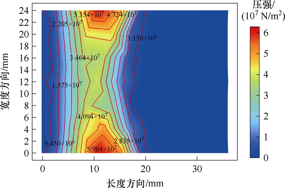
图1 接触面接触压强云图
Fig.1 Contact pressure contour map of the contact surface
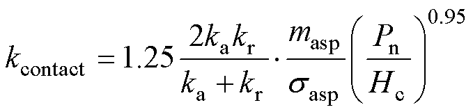
接触界面的电导率与接触压力有关,采用CMY(Cooper-Mikic-Yovanovich)模型计算枢轨界面的接触电导率,不同接触压力下界面接触电导率 [19]为
[19]为
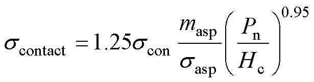 (3)
(3)
式中, 为电枢材料和轨道材料电导率的调和平均值;
 为粗糙表面平均斜率;
 为粗糙表面平均高度;
 为电枢的硬度。
由于电磁发射前期电流较小,电磁压力对接触面接触压力的影响较小,可以适当忽略。将上述接触压强数据代入式(3),计算得到的接触电导率云图如图2所示。从图中可以看出,枢轨界面的接触电导率分布特性与接触压强完全相同,两者仅有数值上的差异,体现了外加接触压力对初始时刻界面接触电阻的影响。
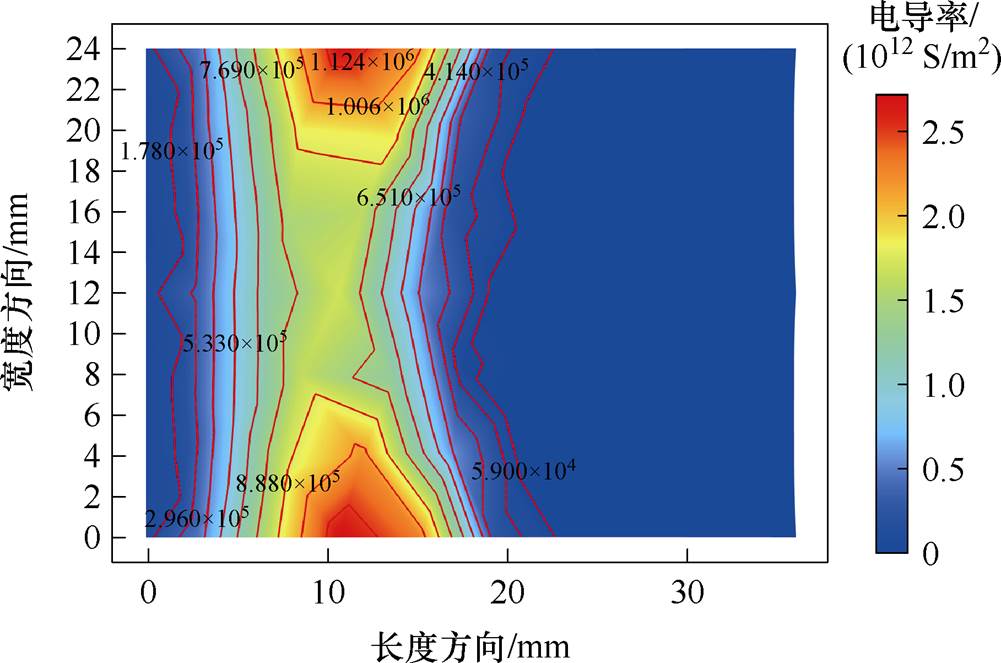
图2 接触面接触电导率云图
Fig.2 Contact surface electrical conductivity contour map
忽略电枢和轨道的体电阻产生的焦耳热对枢轨界面的影响,在金属液膜形成之前,枢轨界面之间的热量来源仅考虑接触电阻的焦耳热与界面间的摩擦热。电枢与导轨的温度分布分别通过式(4)和式(5)的热传递方程来求解。
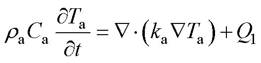 (4)
(4)
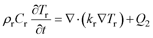 (5)
(5)
式中, 、
、 分别为电枢和轨道的密度;
 、
、 分别为电枢和轨道的恒压热容;
 、
、 分别为电枢与导轨的热导率;
 、
、 分别为电枢和轨道的温度;
 为枢轨界面传递给电枢的接触电阻焦耳热和摩擦热;
 为枢轨界面传递给轨道的接触电阻焦耳热和摩擦热。
接触压力同样也会对界面传热产生影响,界面接触热导率![]() 为
为
 (6)
(6)
在电磁发射过程中,随着电枢的运动,电枢表面温度不断升高,而轨道侧总是新的室温轨道与电枢相接触,枢轨界面两侧的温差越来越大,界面热量向两侧传递的比例也会随之变化。定义热量分配系数 为接触面热量传递给电枢表面的热流密度与接触面总热流密度的比值,即
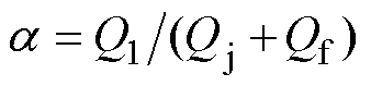 。热量分配系数会随着电枢表面与轨道表面之间温度梯度的增大而减小,直到电枢表面温度达到材料熔点不再上升时,热量分布系数将保持不变[20]。
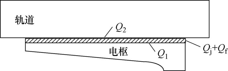
图3 接触面热量传递示意图
Fig.3 Schematic diagram of heat transfer at the contact surface
利用有限元软件对电磁发射电枢表面温度分布进行仿真,图4为建立的三维电磁发射仿真几何模型。
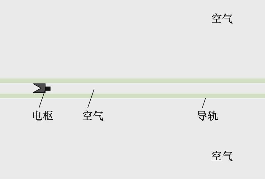
图4 电磁发射仿真几何模型
Fig.4 Geometric model for electromagnetic launch simulation
输入电流的峰值为500 kA,上升沿为0.5 ms,电流仿真波形如图5所示。
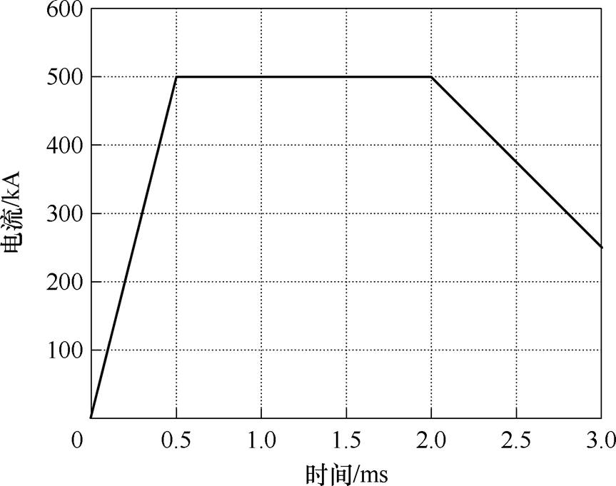
图5 输入电流仿真波形
Fig.5 Input current simulation waveform graph
图6为不同时刻接触面的摩擦热流密度分布。从图中可以看出,不同时刻的摩擦热流密度分布与接触压强分布完全相同,接触压强大的区域摩擦热流密度高,摩擦热流密度随着电枢运动速度的增大而增大。
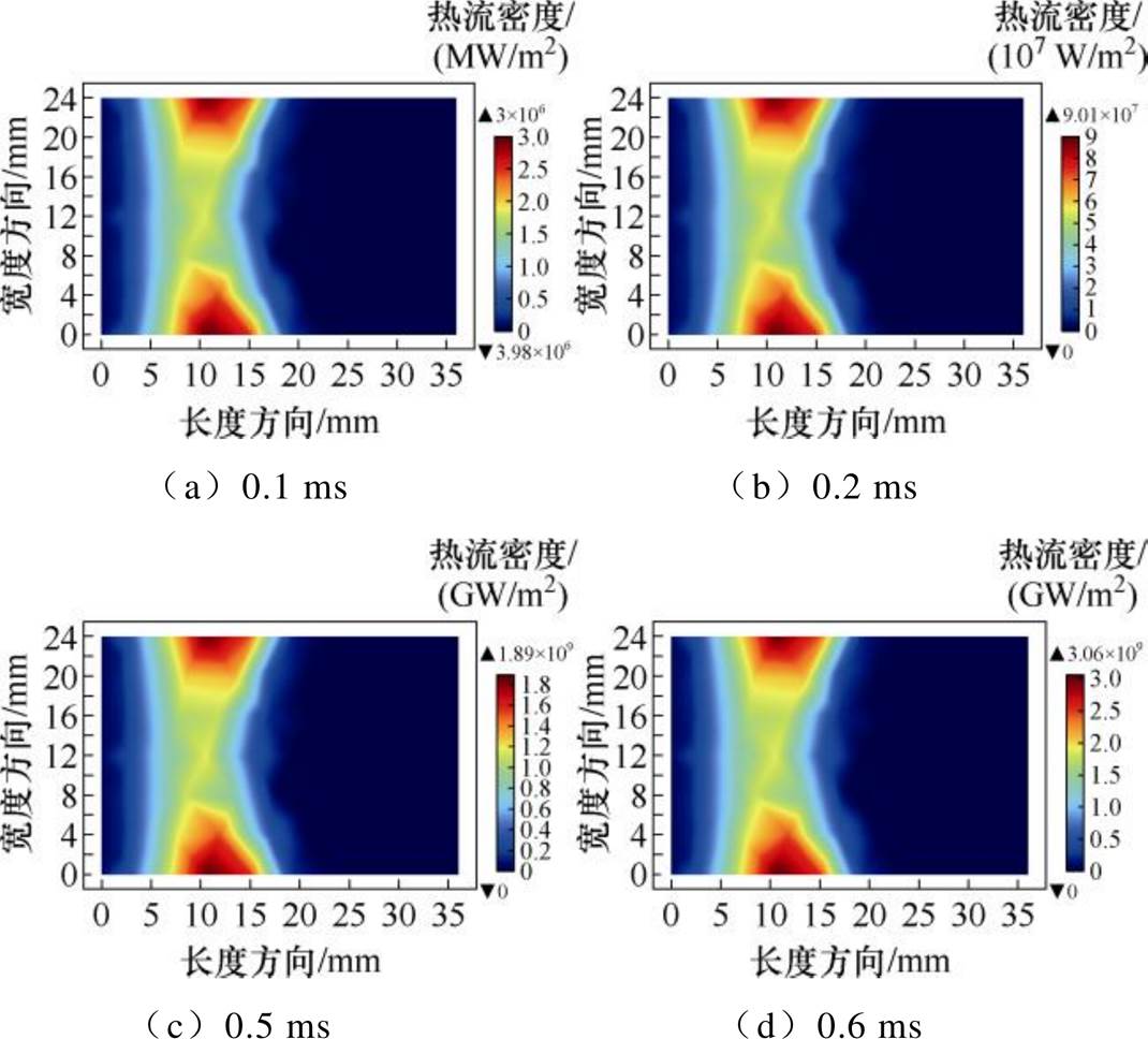
图6 枢轨接触面摩擦热流密度分布
Fig.6 Frictional heating flux density distribution contour map at the armature-rail contact interface
图7为不同时刻接触面的焦耳热流密度分布。从图中可以看出,接触面焦耳热的分布较接触电导率的分布向电枢头部方向移动了10 mm,最大值出现在电枢尾翼长度方向22 mm处,这是由于虽然接触压强大的区域接触电导率大,但是模型中轨道电导率大于电枢电导率,电流从接触区域后端穿过枢轨界面的总路径电导率要大于从接触压强大的区域穿过枢轨界面的总路径电导率,所以电流密度及焦耳热流密度的最大值会出现在接触压强最大区域的后方
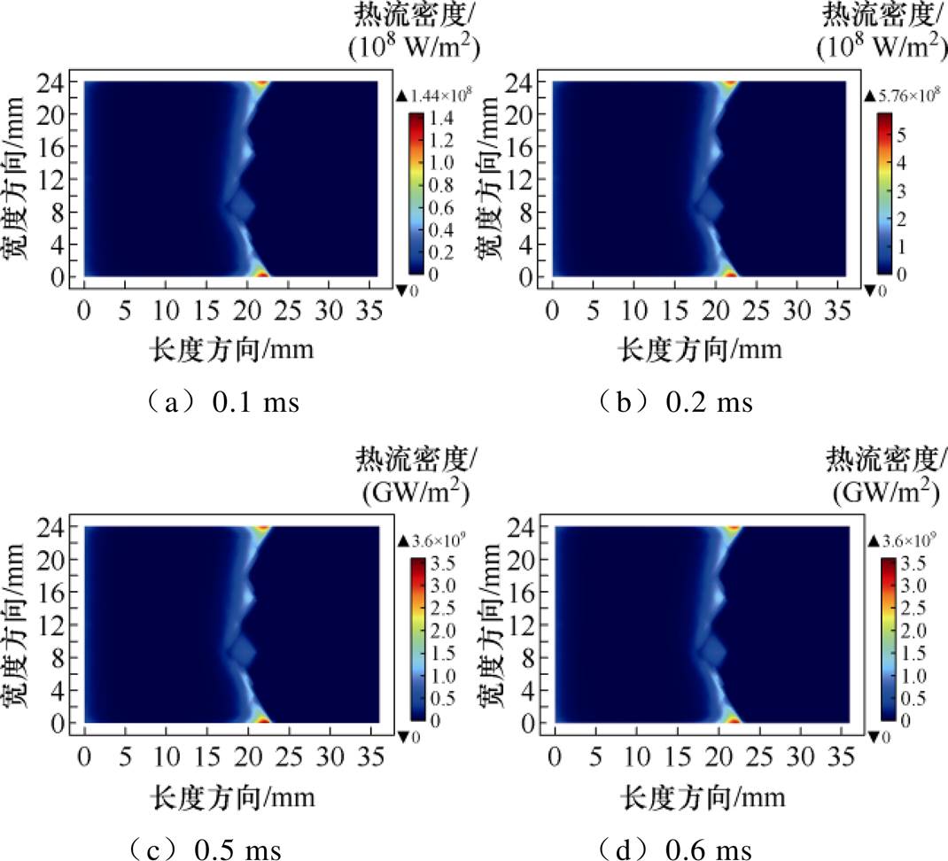
图7 枢轨接触面焦耳热流密度分布
Fig.7 Joule heating flux density distribution contour map at the armature-rail contact interface
。
图8为不同时刻枢轨界面焦耳热与摩擦热热流密度最大值曲线。从图中可以看出,焦耳热热流密度最大值曲线与输入电流变化趋势相同。在初始阶段,电枢运动速度低,摩擦热热流密度最大值远小于焦耳热。随着输入电流达到最大值并保持不变,电枢运动速度不断增加,焦耳热热流密度保持最大值不变,摩擦热热流密度最大值快速上升并逐渐超过焦耳热。在1 ms时刻,摩擦热热流密度最大值约为焦耳热热流密度最大值的2倍。
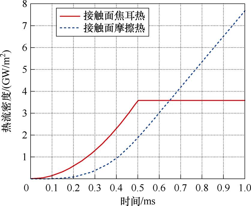
图8 枢轨接触面焦耳热和摩擦热的热流密度最大值曲线
Fig.8 Curves of the maximum joule heating flux density and maximum frictional heating flux density at the armature-rail contact interface
图9为不同时刻电枢表面温度分布。从图中可以看出,电枢表面温度分布与焦耳热热流密度和摩擦热热流密度分布直接相关,这是由于电磁发射过程极快,热传递时间短导致的。在0.6 ms之前,接触面最大温度分布在焦耳热热流密度最大值处,在0.7 ms之后,接触面最大温度分布在摩擦热热流密度最大值处。随着电枢运动速度增加,摩擦热不断增大,电枢表面高温区域开始向电枢尾翼延伸,并且由电枢表面边沿向中间发展,在电枢尾翼形成块状高温区域。
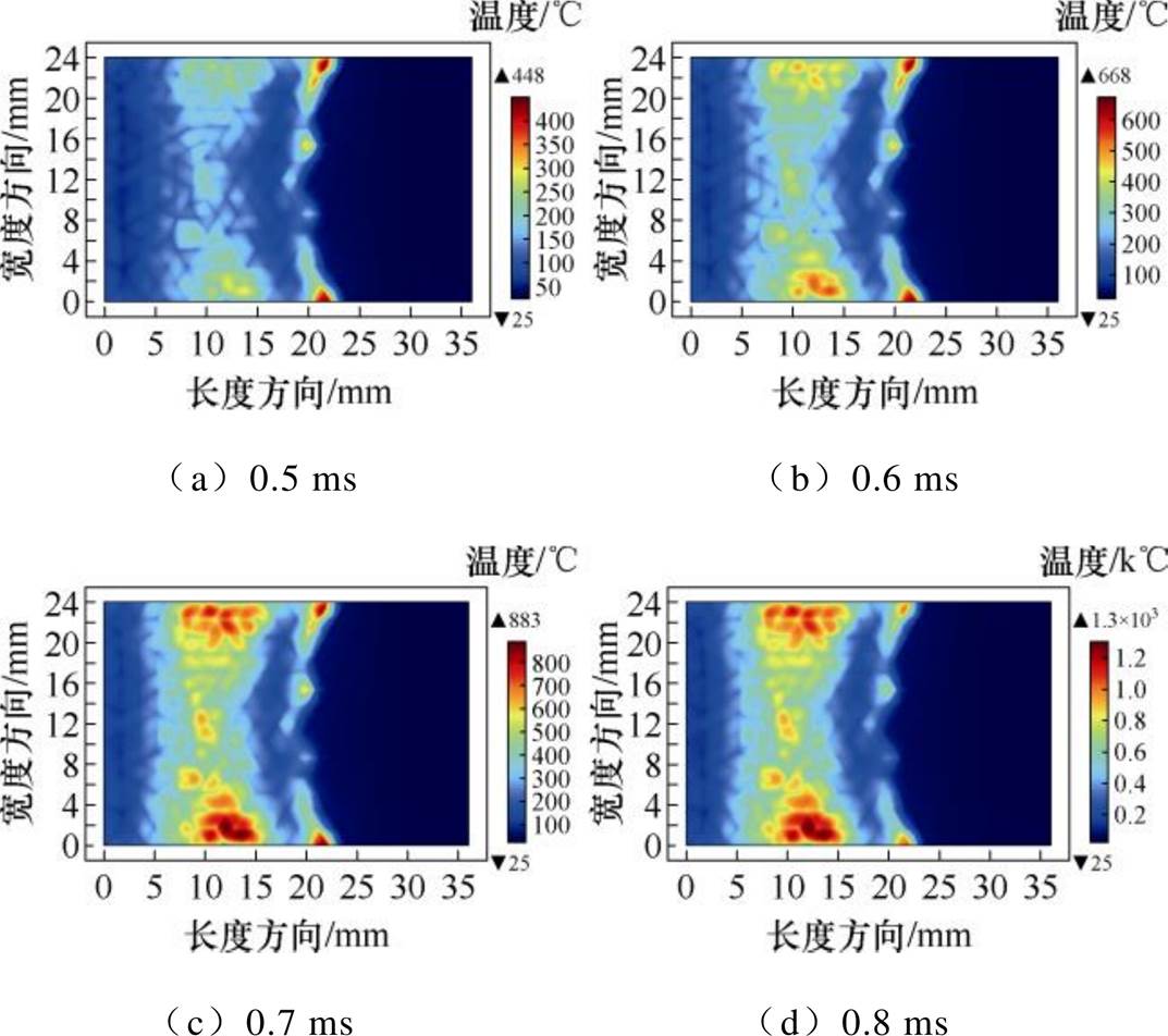
图9 枢轨接触面温度分布
Fig.9 Temperature distribution contour map at the armature-rail contact interface
图10为电枢表面最大温度随时间变化曲线。从图中可以看出,由于焦耳热及摩擦热都很小,初始时刻电枢表面温度上升比较慢。随着热源的快速增大,电枢表面温度上升的速度越来越快,电枢表面最大温度在大约0.55 ms时到达电枢材料的熔点560℃,若忽略电枢熔蚀吸收的热量,电枢表面最大温度将继续升高,达到数千摄氏度。由此可知,在电磁发射中后期,电枢表面一定发生了剧烈的熔蚀。电枢熔蚀吸收了一定的热量,产生了具有润滑作用的液态金属,将会对枢轨界面间的温度分布及接触状态产生非常重要的影响。
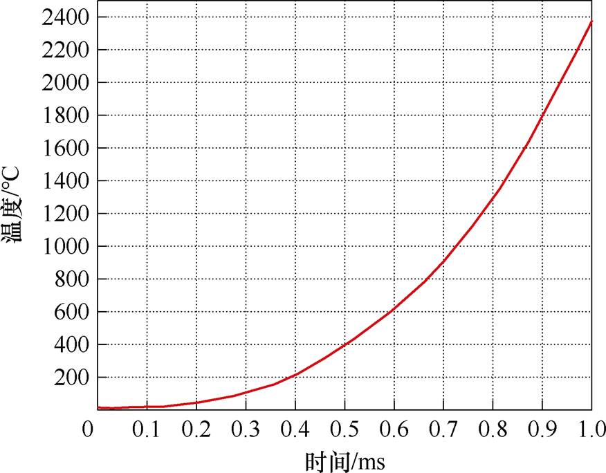
图10 电枢表面最大温度曲线
Fig.10 Maximum surface temperature curve of the armature
当电枢温度达到材料熔点之后,继续吸收热量,温度却保持不变,吸收的热量全部用以增大电枢材料分子间的位能,直到电枢表面由固态金属变为液态金属,完成物态的变化,这就是电枢熔蚀过程。电枢熔蚀可以通过Stefan条件来进行研究,通过计算电枢表面热量来源及温度分布可以确定电枢表面的熔蚀情况。相变界面上的热平衡条件为
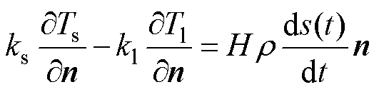 (7)
(7)
式中, 、
、 分别为电枢材料固相和液相的温度;
 、
、 分别为电枢材料固相和液相的热传递系数;
 为电枢材料液相的密度;
 为电枢材料熔化潜热;
 为固液分界面上指向液体区域的法向单位矢量;
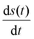 为电枢熔蚀速度。
由于电枢发生熔蚀时运动速度已经很快,电枢熔蚀过程时间短,因此,认为枢轨界面热量直接传递给电枢熔蚀区,忽略液相区温度变化及熔蚀区向固相区传递的热量,熔蚀阶段电枢的全部热量被熔蚀区吸收。因此可通过式(8)计算电枢表面熔蚀 深度。
 (8)
(8)
图11为不同时刻电枢表面的熔蚀仿真。从图中可以看出,0.7 ms时电枢表面首先出现了点状熔蚀,熔蚀最大深度出现在焦耳热热流密度最大值处。随着时间的增加,枢轨界面摩擦热不断增大,电枢尾部开始出现明显的块状熔蚀,熔蚀最大深度也转移到摩擦热热流密度最大值处,同时电枢表面熔蚀区域开始由两侧尾部边沿向中间发展,两侧熔蚀区域呈现会合的趋势。
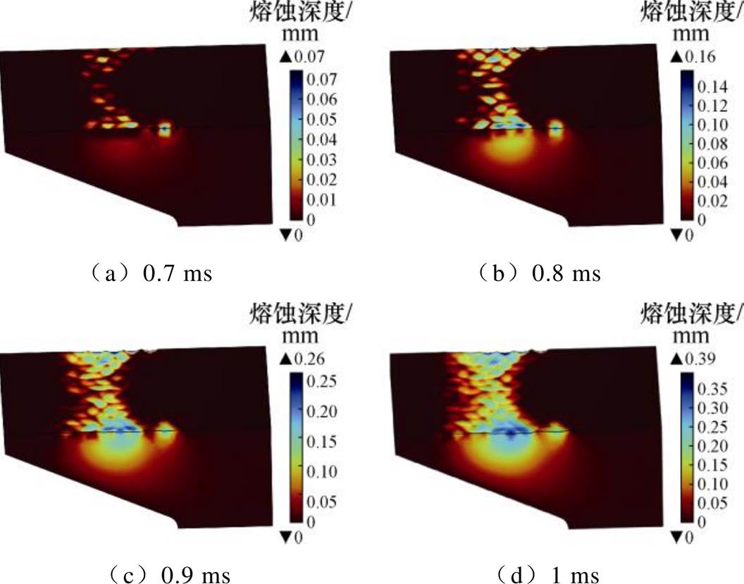
图11 电枢表面熔蚀仿真
Fig.11 Simulation map of armature surface erosion
在电磁发射初始阶段,焦耳热首先在电枢表面产生电流熔蚀,由于电枢表面电流密度分布不均匀,电流熔蚀呈现点状分布。由焦耳热导致的点状熔蚀的熔蚀质量小,液态铝产生后将迅速冷却附着在轨道表面,无法在枢轨界面间形成具有润滑作用的金属液膜。当摩擦热随着电枢运动速度加快而增大时,电枢表面熔蚀开始呈现扩张性趋势,即从电流密度集中区域沿边缘向电枢尾部方向发展,同时熔蚀开始从电枢边沿向电枢中部发展,熔蚀面积显著增大,熔蚀产生的液态铝越来越多。随着熔蚀质量的不断增加,液态铝开始逐渐附着在枢轨界面间,覆盖电流熔蚀产生的熔坑,在维持枢轨界面间良好的电接触方面起到积极作用。当液态铝质量达到一定的程度,所有电流熔蚀导致的熔坑均被覆盖,之后产生的液态铝将随电枢一起在轨道内滑动,在枢轨界面间形成具有润滑作用的液态金属层,改变枢轨间原本的固-固摩擦状态。此后,枢轨界面摩擦热的来源将从固-固摩擦热转变为金属液化层带来的黏滞摩擦热。
从图9~图11可以看出,电枢表面最大温度在0.55 ms时到达电枢材料熔点,而电枢表面在0.7 ms才出现较为明显的熔蚀,考虑电枢熔蚀前吸收潜热的过程,熔蚀发生前焦耳热热流密度最大值一直大于摩擦热热流密度最大值,且0.7 ms时电枢熔蚀深度最大的位置位于焦耳热热流密度最大值处,因此可以认为焦耳热是电枢起始熔蚀的主要原因。
从图9和图11中可以看出,0.7 ms之后,随着摩擦热热流密度最大值逐渐大于焦耳热热流密度最大值,电枢表面温度最大值开始出现在摩擦热热流密度最大值处,电枢熔蚀形貌也逐渐与摩擦热热流密度分布一致,电枢熔蚀最大深度也移动到摩擦热热流密度最大值处,因此可以认为摩擦热是决定最终电枢最大熔蚀深度的主要原因。
华中科技大学团队对电磁发射中电枢熔蚀情况进行了一系列实验研究,积累了丰富的经验与实验数据,以该团队的一次低速小电流电磁发射实验结果对本文提出的电枢熔蚀模型进行验证。该实验中输入电流峰值为333.2 kA,上升时间约1.5 ms,采用C型电枢,发射总质量为407.861 g,实验详细参数见文献[12]。实验结束后,电枢膛内运动位移为26 cm,利用日本三峰CV1000N2探针式轮廓仪对回收的电枢表面进行测量,电枢表面熔蚀深度测量图[12]如图12所示。结果表明,电枢表面熔蚀呈现扩张性模式,表面最大熔蚀深度为0.44 mm。
采用上述实验参数建立电磁发射电枢表面熔蚀模型,仿真结果如图13所示。从图中可以看出,电枢表面的最大熔蚀深度为0.46 mm,最大熔蚀深度出现在摩擦热热流密度最大值处,仿真所得的电枢表面熔蚀形貌与实验基本相同,证明了本文所建立的电枢熔蚀模型的准确性。
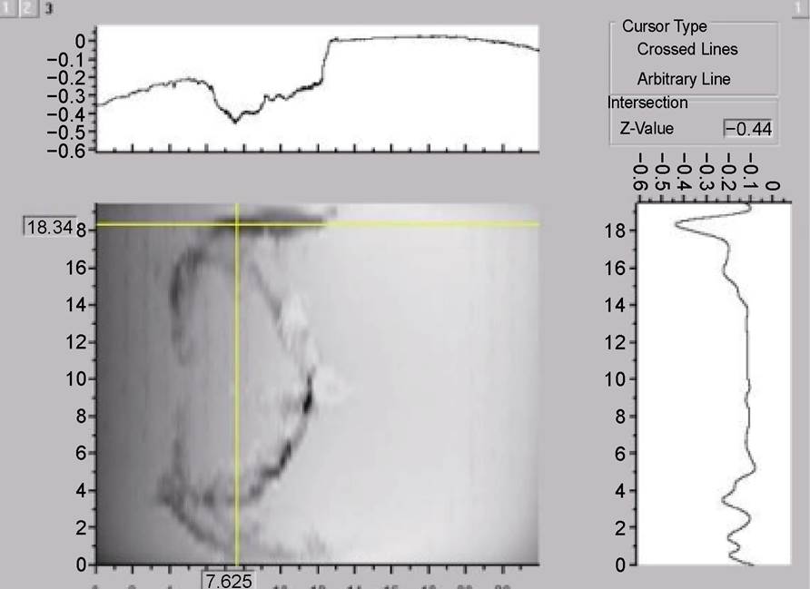
图12 电枢表面熔蚀深度测量图
Fig.12 Measurement graph of armature surface erosion depth
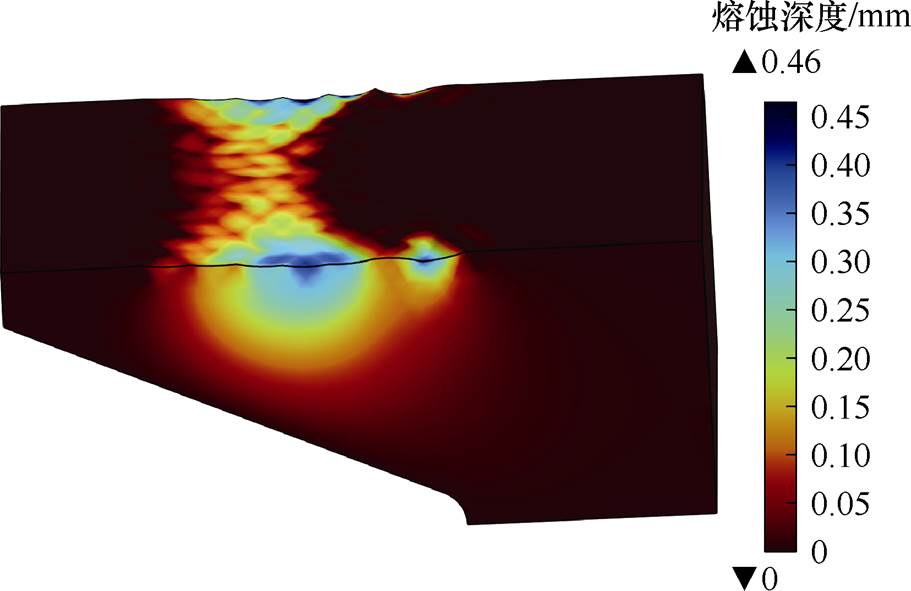
图13 电枢表面熔蚀仿真
Fig.13 Simulation map of armature surface erosion
本文建立了考虑接触压力与接触电阻的三维电磁发射多物理场耦合模型,通过计算电枢表面的焦耳热流密度与摩擦热流密度得到了电磁发射前期电枢表面的温度分布特性,并通过Stefan相变条件研究了电枢表面的熔蚀特性,得到了以下结论:
1)枢轨界面接触电导率与接触压强分布相同,距离接触面边沿越近,接触压强与接触电导率的值越大,C型电枢接触压强与接触电导率的最大值均集中在尾翼中段的范围内。
2)在电枢低速运动阶段,焦耳热是枢轨接触面的主要热量来源,电流分布不均匀的特性会在电枢中部表面形成点状熔蚀。随着电枢运动速度的增大,枢轨接触面的摩擦热迅速上升,电枢表面熔蚀开始由电枢中部向电枢尾部发展,由点状熔蚀发展成扩张性熔蚀,最终形成贯通性熔蚀。
3)电枢起始熔蚀位置是接触面电流密度最大的位置,而电枢熔蚀的最大深度出现在接触面接触压强最大的位置。因此,电枢表面的起始熔蚀主要与焦耳热有关,电枢表面的最大熔蚀深度主要与摩擦热有关。
参考文献
[1] 马伟明, 鲁军勇. 电磁发射技术的研究现状与挑战[J]. 电工技术学报, 2023, 38(15): 3943-3959.
Ma Weiming, Lu Junyong. Research progress and challenges of electromagnetic launch technology[J]. Transactions of China Electrotechnical Society, 2023, 38(15): 3943-3959.
[2] 李兵, 李卫超, 荆从凯. 电磁发射系统研究现状及应用展望[J]. 兵器装备工程学报, 2023, 44(10): 173- 181.
Li Bing, Li Weichao, Jing Congkai. Research status and application prospects of electromagnetic launch system[J]. Journal of Ordnance Equipment Engin- eering, 2023, 44(10): 173-181.
[3] 翟小飞, 李鑫航, 刘华, 等. 电磁轨道发射系统电路模型及发射效率研究[J]. 电工技术学报, 2023, 38(11): 2841-2849, 2860.
Zhai Xiaofei, Li Xinhang, Liu Hua, et al. Research on circuit model and launch efficiency of electro- magnetic rail launch system[J]. Transactions of China Electrotechnical Society, 2023, 38(11): 2841-2849, 2860.
[4] 阮景煇, 陈立学, 夏胜国, 等. 电磁轨道炮电流分布特性研究综述[J]. 电工技术学报, 2020, 35(21): 4423-4431.
Ruan Jinghui, Chen Lixue, Xia Shengguo, et al. A review of current distribution in electromagnetic railguns[J]. Transactions of China Electrotechnical Society, 2020, 35(21): 4423-4431.
[5] Stefani F, Merrill R. Experiments to measure melt- wave erosion in railgun armatures[J]. IEEE Transa- ctions on Magnetics, 2003, 39(1): 188-192.
[6] Watt T, Stefani F. The effect of current and speed on perimeter erosion in recovered armatures[J]. IEEE Transactions on Magnetics, 2005, 41(1): 448-452.
[7] 巩飞, 翁春生. 电磁轨道炮固体电枢熔化波烧蚀过程的三维数值模拟研究[J]. 高电压技术, 2014, 40(7): 2245-2250.
Gong Fei, Weng Chunsheng. 3-D numerical study of melt-wave erosion in solid armature railgun[J]. High Voltage Engineering, 2014, 40(7): 2245-2250.
[8] 谭赛, 鲁军勇, 张晓, 等. 导轨式电磁发射装置电枢熔化波有限元计算[J]. 西安交通大学学报, 2016, 50(3): 106-111.
Tan Sai, Lu Junyong, Zhang Xiao, et al. Finite element analysis of melt wave ablation in elec- tromagnetic rail launcher armatures[J]. Journal of Xi’an Jiaotong University, 2016, 50(3): 106-111.
[9] 陈立学, 何俊佳, 夏胜国, 等. 电磁轨道炮轨道电阻率和轨道高度对电流上升沿阶段电枢边沿熔蚀的影响[J]. 高电压技术, 2014, 40(4): 1071-1076.
Chen Lixue, He Junjia, Xia Shengguo, et al. Influence of rail resistivity and rail height on armature edge erosion at current ramp-up in solid armature railgun[J]. High Voltage Engineering, 2014, 40(4): 1071-1076.
[10] 朱仁贵, 张倩, 李治源, 等. 高功率脉冲电流作用下滑动界面初始熔蚀的试验研究[J]. 高电压技术, 2015, 41(6): 1879-1884.
Zhu Rengui, Zhang Qian, Li Zhiyuan, et al. Experiment research on initial melt erosion at the sliding interface under high power pulse current[J]. High Voltage Engineering, 2015, 41(6): 1879-1884.
[11] 汤亮亮, 张广洲, 夏胜国, 等. 小口径电磁轨道炮电枢电流熔蚀特性实验研究[J]. 高电压技术, 2016, 42(9): 2857-2863.
Tang Liangliang, Zhang Guangzhou, Xia Shengguo, et al. Experimental study of the melt-wave erosion of armature in small-caliber railgun[J]. High Voltage Engineering, 2016, 42(9): 2857-2863.
[12] 胡宇阳. 电磁发射小口径电枢电流熔蚀特性研究[D]. 武汉: 华中科技大学, 2017.
Hu Yuyang. Study on current erosion characteristics of electromagnetic emission small-caliber armature[D]. Wuhan: Huazhong University of Science and Tech- nology, 2017.
[13] 李白, 鲁军勇, 谭赛, 等. 滑动电接触界面粗糙度对电枢熔化特性的影响[J]. 电工技术学报, 2018, 33(7): 1607-1615.
Li Bai, Lu Junyong, Tan Sai, et al. Effect of interfacial roughness of sliding electrical contact on the melting characteristics of armature[J]. Transa- ctions of China Electrotechnical Society, 2018, 33(7): 1607-1615.
[14] Yao Jinming, Xia Shengguo, Chen Lixue, et al. Analysis of the melt erosion patterns at rail- armature contact of rail launcher in current range of 10- 20 kA/mm[J]. IEEE Transactions on Plasma Science, 2019, 47(3): 1674-1680.
[15] 耿轶青, 刘辉, 马增帅, 等. 电磁轨道炮枢轨的动态焦尔热特性[J]. 高电压技术, 2019, 45(3): 799- 804.
Geng Yiqing, Liu Hui, Ma Zengshuai, et al. Armature and rail’s dynamic joule heating characteristic of the electromagnetic railguns[J]. High Voltage Engin- eering, 2019, 45(3): 799-804.
[16] Li Bai, Ma Weiming, Lu Junyong, et al. Effects of supply current and armature structure on melting characteristics of armature surface in sliding electric contact[J]. IEEE Transactions on Plasma Science, 2019, 47(1): 721-728.
[17] 李白, 鲁军勇, 谭赛, 等. 高速滑动电接触电枢表面动态磨损过程研究[J]. 电工技术学报, 2023, 38(1): 131-139.
Li Bai, Lu Junyong, Tan Sai, et al. Research on dynamic wear process of armature surface in high- speed sliding electric contact[J]. Transactions of China Electrotechnical Society, 2023, 38(1): 131-139.
[18] 姚金明, 孙建东, 鲍建波, 等. 滑动电接触界面沉积层对电枢熔化的抑制效应研究[J]. 电工技术学报, 2024, 39(19): 5958-5968.
Yao Jinming, Sun Jiandong, Bao Jianbo, et al. Study on suppressing effect of deposited layer on armature melting at sliding electrical contact interfaces[J]. Transactions of China Electrotechnical Society, 2024, 39(19): 5958-5968.
[19] Yovanovich M M. Four decades of research on thermal contact, gap, and joint resistance in micro- electronics[J]. IEEE Transactions on Components and Packaging Technologies, 2005, 28(2): 182-206.
[20] 姚金明, 傅强. 大电流高速滑动电接触界面热量分配过程[J]. 电工技术学报, 2024, 39(17): 5497-5507.
Yao Jinming, Fu Qiang. Heat partition process at sliding electrical contact interfaces with high-speed and large current[J]. Transactions of China Electro- technical Society, 2024, 39(17): 5497-5507.
Abstract The armature erosion during the electromagnetic launching process disrupts the contact between the armature and the rails, significantly impairing the performance of the launch. Joule heating and frictional heating, originating from different mechanisms, affect armature erosion in distinct ways. Current research on armature erosion focuses on current-induced Joule heating, with relatively limited studies on erosion caused by frictional heating. This paper establishes an armature surface erosion model that incorporates the effects of frictional heating. The model analyzes the impact of both Joule and frictional heating on armature surface erosion during the early stages of the launch and validates the results with experimental data.
Firstly, the contact state between the armature and the rails under the influence of contact pressure is analyzed. The contact pressure distribution on the contact surface is significantly non-uniform in the early stages of the launch, with the contact conductance distribution corresponding closely to the contact pressure distribution. Subsequently, the Joule and frictional heat fluxes at the armature-rail interface are calculated separately. Due to differences in the electrical conductivity of the armature and rail materials, the distribution of Joule heat flux is shifted approximately 10 mm towards the armature head compared to the distribution of contact pressure. In contrast, the distribution of frictional heat flux closely aligns with the distribution of contact pressure. As the velocity of the armature increases during the launch, frictional heating initially contributes less than Joule heating but eventually surpasses it.
The temperature distribution characteristics on the armature surface are studied. The results indicate that the armature’s maximum surface temperature exceeds the melting point of the armature material before the maximum frictional heat flux surpasses the maximum Joule heat flux. With the rapid increase in frictional heat during the launch process, the location of the maximum surface temperature shifts from the position of the maximum Joule heat flux density to that of the maximum frictional heat flux density. The Stefan condition for phase transition is used to investigate the erosion process on the armature surface. The results demonstrate that during the initial stage of the launch, surface erosion first occurs at the point of maximum Joule heat flux, presenting as localized current erosion. As the armature velocity increases, the erosion region expands from the rear edges towards the center, with the maximum erosion depth shifting to the point of maximum frictional heat flux.
A low-speed, low-current electromagnetic launch experiment is conducted by the Huazhong University of Science and Technology team. Based on the parameters of this experiment, the simulated armature erosion profile closely matches the experimental results, with the maximum surface erosion depth measured at 0.44 mm in the experiment and 0.46 mm in the simulation. Analysis of the armature surface erosion profiles at different time points indicates that during the low-speed phase, Joule heating predominantly governs armature erosion, with initial erosion primarily attributed to Joule heating. As the armature velocity increases, the influence of frictional heating on armature erosion gradually surpasses that of Joule heating, making frictional heating the primary factor in determining the maximum erosion depth.
keywords:Electromagnetic launch, joule heating, frictional heating, armature erosion, Stefan phase change
DOI: 10.19595/j.cnki.1000-6753.tces.240884
中图分类号:TM359.4
国家自然科学基金资助项目(92166204)。
收稿日期 2024-05-27
改稿日期 2024-07-05
娄建勇 男,1975年生,博士,副教授,研究方向为特种电机的优化与控制。E-mail: jylou@mail.xjtu.edu.cn(通信作者)
徐 顺 男,1999年生,硕士研究生,研究方向为电磁发射技术。E-mail: 1665472192@qq.com
(编辑 崔文静)