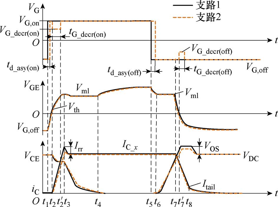
图1 IGBT并联门极差压异步驱动控制原理
Fig.1 IGBT parallel gate pole differential pressure asynchronous drive method schematic diagram
摘要 动态均流是限制多IGBT模块并联应用的关键问题。开通电流时刻,电流上升率和电流峰值等过程变量形式影响多支路IGBT开关过程的一致性。基于并联支路IGBT驱动控制回路的固有参数差异,该文提出并联IGBT差压异步驱动技术,通过调节驱动脉冲异步间隙和改变驱动电压幅值与持续时间,协调控制不同支路的IGBT门极脉冲,驱动各支路IGBT开关过程电流一致。研究开关过程中驱动信号异步间隙、驱动差压与电压调整时间对动态电流斜率不均衡度的影响,分析控制参数耦合关系,优化参数设定方法。基于实际IGBT模块参数,建立器件工作特性数学模型,进行IGBT并联开关仿真分析,开展应用该方法的驱动实际工况测试,结果表明,所选优化设计参数可以明显改善IGBT模块并联开关动态均流特性,验证了差压异步驱动控制优化参数设计方法的可行性。
关键词:IGBT并联 均流特性 驱动差压 异步间隙
绝缘栅双极型晶体管(Insulated Gate Bipolar Transistor, IGBT)模块并联应用是一种有效提升系统功率等级的方法,在轨道交通[1-3]、海上风电[4-5]、固态断路器[6-7]等行业应用广泛。由于阈值电压和输入电容等模块自身参数差异,或驱动控制回路和功率回路布局不对称等原因,导致并联模块开关时刻不一致或电流上升率和下降率存在差异,产生了并联均流问题[8-13]。一些学者提出了改善并联均流特性的方法,如驱动信号磁耦合控制法、门极电阻补偿法、有源门极控制法等[14-17],文献[18]提出了一种应用改进的GLD互联型缓冲电路来实现动态均流的方法,通过在硬件电路中引入缓冲电阻、缓冲电感、二极管等元器件在开关过程均可起到动态均流的作用,较为复杂。文献[19]提出一种调节驱动信号的触发延时来实现并联模块集电极电流分布趋于一致的同步脉冲异步驱动控制方法,可以在一定程度上降低电流不均衡度,但在参数差异很小的精确控制范围内补偿效果较差。文献[20]比较了基于敏感参数的变电压、变电阻、变电流主动栅极驱动技术,提出了通过多级电平合成电路调整驱动电压幅值的控制方法,该方法虽然在开通过程可以有效改善动态均流特性,但是关断过程改善效果很差。
本文研究了开关过程关键阶段各控制参数间的协调关系以及对均流特性的影响,分析对均流特性的最优补偿范围,优化延迟时间、门极电压变化幅值和变电压持续时间3个参数设定。提出一种差压异步驱动技术,通过调节并联IGBT模块控制回路的驱动信号异步间隙、驱动差压及电压调整时间,更精准地控制动态电流,改善了由于开关时刻不同步或电流斜率不一致而造成的动态均流问题。通过多模块并联实验分析,验证该方法对动态均流特性的改善效果。
差压异步驱动方法的整体思路是在IGBT的开关过程中,针对开通关断异步间隙进行补偿,调整驱动信号开始跳变的时刻,并且在不同阶段施加不同的驱动差压,以降低用集电极电流斜率di/dt所表征的电流动态不均衡度,其控制原理如图1所示。图1中,VG为门极电压,VG,on为门极额定开通电压,VG_decr(on)为门极低开通电压,VG_dec(off)为门极低关断电压,VGE为门极发射极电压,VG,off为门极额定关断电压,Vth为门极开通阈值电压,Vm1为米勒平台电压,VCE为集电极发射极电压,Vos为压差,VDC为直流电压,iC为集电极电流,Irr为反向恢复电流,IC_x为支路电流,Itail为拖尾电流,td_asy(on)为开通异步时延,td_asy(off)为关断异步时延,tG_decr(on)为门极低开通电压时间,tG_decr(off)为门极低关断电压时间。

图1 IGBT并联门极差压异步驱动控制原理
Fig.1 IGBT parallel gate pole differential pressure asynchronous drive method schematic diagram
集电极电流上升阶段 t2, t3
 :开通过程等效电流斜率如图2所示,设参考支路(x=1)在电压VG,on作用下的电流上升率为
 ,实际情况下回路存在参数差异或模块自身差异的支路(x= 2, 3,…)在异步间隙为td_asy(on)_x,驱动差压为VG_decr(on)_x,电压调整时间为tG_decr(on)_x作用下的电流上升率为
 ;驱动电压为VG,on时,电流上升率为
 ,电流从零上升到负载电流阶段的等效电流斜率为
 ,则根据电流等效原则得
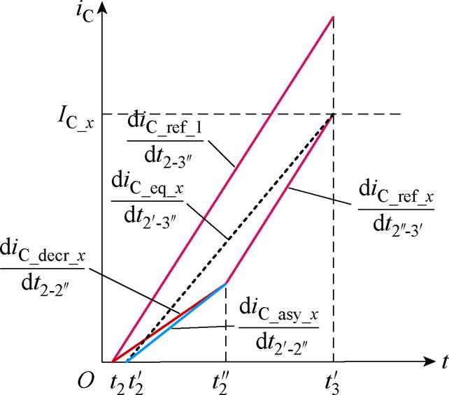
图2 开通过程等效电流斜率
Fig.2 The equivalent current slope diagram in the turn-on

 (1)
(1)
集电极电流下降阶段 t7, t8
 :根据图3所示关断过程等效电流原则,解得关断等效电流斜率
  为
为
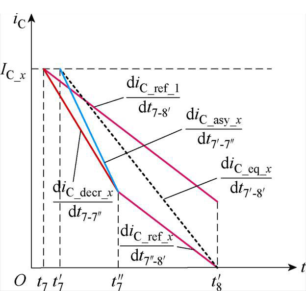
图3 关断过程等效电流斜率
Fig.3 The equivalent current slope diagram in the turn-off

 (2)
(2)
IGBT模块并联集电极电流动态不均衡度d 用电流斜率表征,定义
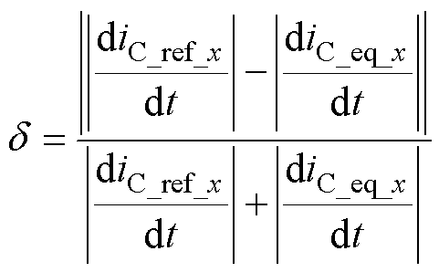 (3)
(3)
引入不均衡度改善因子 ,其公式为
,其公式为
 (4)
(4)
式中,d0为引入补偿前并联模块动态电流不均衡度;d 为引入补偿后动态电流不均衡度。
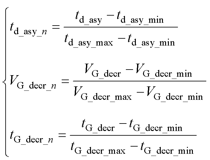
基于实际大功率应用场景IGBT开关特性和驱动电路控制特性,设定开通过程异步间隙-8~8 ns,电压调整时间5~30 ns,变电压10~18 V;关断过程异步间隙-8~8 ns,电压调整时间5~30 ns,变电压-20~-12 V。对变量进行归一化处理如式(5)所示,设定异步间隙归一化值td_asy_n、驱动差压归一化值VG_decr_n、电压调整时间归一化值tG_decr_n分别为
 (5)
(5)
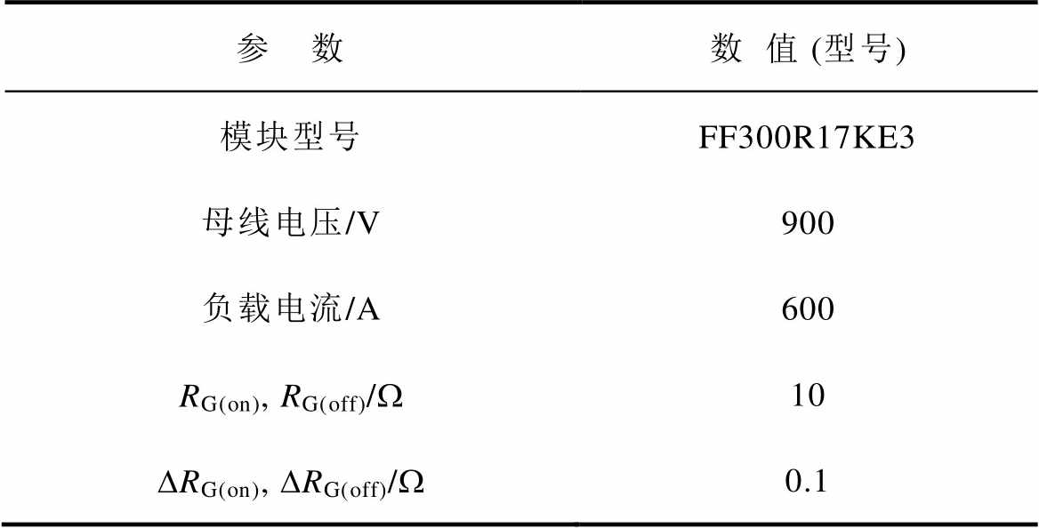
进行两IGBT模块并联的PSpice仿真,参数设置见表1。
表1 两IGBT模块并联双脉冲测试仿真参数设置
Tab.1 2 IGBT parallelled simulation parameter setting
参 数数值 (型号) 模块型号FF300R17KE3 母线电压/V900 负载电流/A600 RG(on), RG(off)/W10 DRG(on), DRG(off)/W0.1
图4所示为采用不同参数设定的差压异步驱动并联IGBT开关过程仿真,描述间隙归一化值td_asy_n、调整时间归一化值tG_decr_n和变电压值归一化值VG_decr_n三个影响因素对电流不均衡改善度Dd 的约束关系。以开关门极电压VG,on=15 V,VG,off= -15 V(黄色平面)为基准,差压驱动以此基准进行变电压幅值。以作用时刻td_asy(on)=0 ns,td_asy(off)=0 ns(红色平面)为基准,异步驱动以此基础进行开通关断电压延迟时间调整。颜色由红到蓝表示不均衡度改善效果由差到好,可看出开通过程差压异步驱动对于电流不均衡的最优改善效果为-2.1%,关断过程差压异步驱动对于电流不均衡度的最优改善效果为-0.9%,说明差压异步驱动对开通和关断过程均有明显的补偿效果。
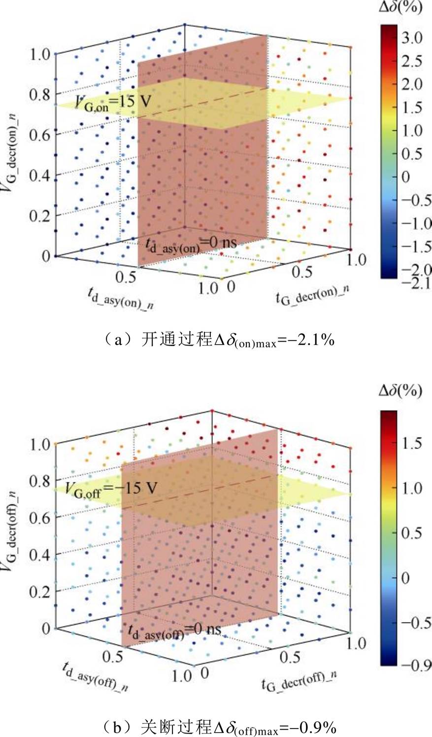
图4 仿真td_asy_n-tG_decr_n-VG_decr_n-Dd 关系
Fig.4 Simulation of td_asy_n-tG_decr_n-VG_decr_n-Dd
基于驱动电路功能和IGBT器件的特性,变量参数范围做了一定限制,时间变量控制在30 ns以内,分辨率1 ns,电压幅值升降幅度控制在5 V,分辨率1 V。采用批量梯度下降法进行参数优化,以获得最好均衡度改善效果时的优化参数设计。优化算法设定异步间隙归一化值td_asy_n、电压调整时间归一化值tG_decr_n、驱动差压归一化值VG_decr_n,输出为不均衡度改善因子Dd。将各支路IGBT驱动控制回路的差异等效为阻抗差异,取DRG(on)=1%RG,开通过程不均衡度仿真输出结果如图5a所示,关断过程如图5b所示。当Dd <0时,差压异步驱动方法具有改善并联均流问题的效果,且不均衡度改善因子负方向越大,改善效果越好。
在VG_decr(on)_n在0.6~1.0之间时,有一个不均衡度改善因子值曲面成为开通过程差压异步驱动方法动态电流不均衡度改善效果最优曲面。截取不均衡度改善因子小于-0.73%的最优曲面,如图6a所示。在VG_decr(off)_n为0~0.6之间时,有一个不均衡度改善因子曲面成为关断过程中差压异步驱动方法的动态电流不均衡度改善效果最优曲面。截取不均衡度改善因子小于-0.95%的最优曲面,如图6b所示。
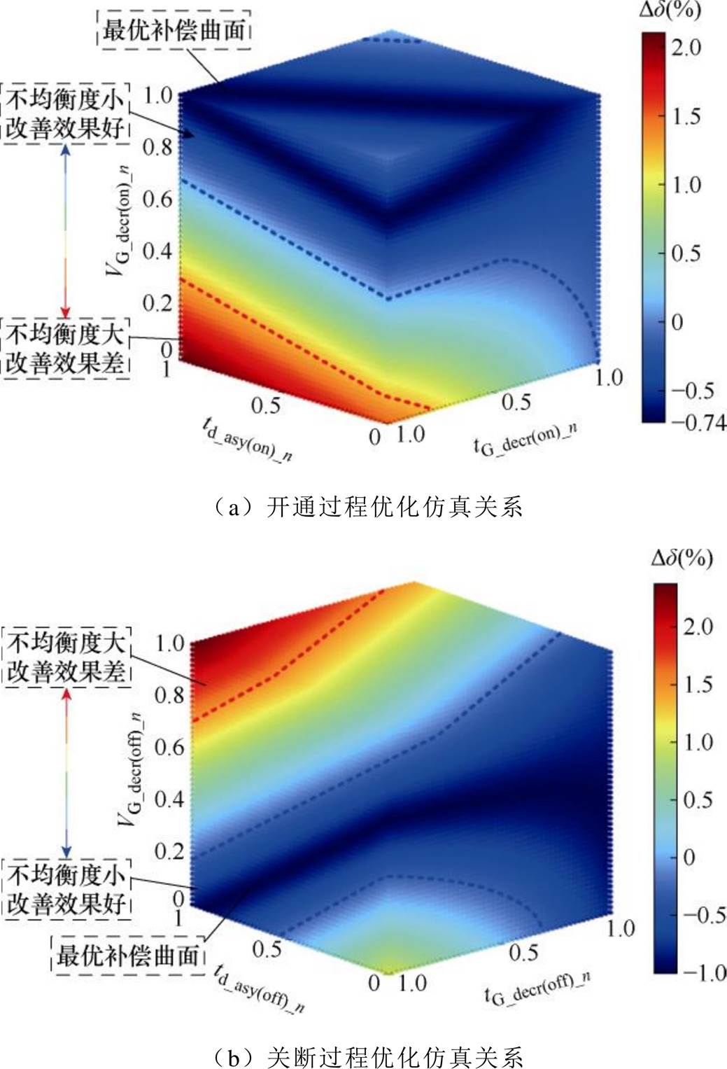
图5 td_asy_n-tG_decr_n-VG_decr_n-Dd 优化关系
Fig.5 td_asy_n-tG_decr_n-VG_decr_n-Dd optimizition
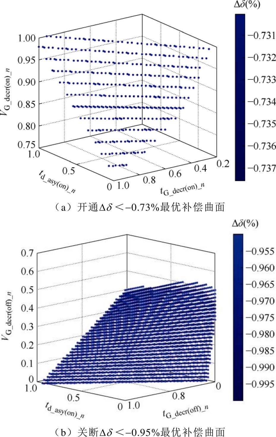
图6 开关过程最优补偿曲面
Fig.6 The optimal compensation surface on switching process
开通过程最优补偿曲面随机数据点波形如图7所示。图7中,VGE1为1支路门极发射极电压,VGE2为2支路门极发射极电压,VG1为1支路门极电压,VG2为2支路门极电压,IC1为1支路集电极电流,IC2为2支路集电极电流;DIrr(on)为反向恢复电流差异,d(on)为开通不均衡度。补偿前不均衡度为1.07%,如图7a所示。取多组最优曲面数据点进行验证,波形如图7b~图7d所示,动态电流不均衡度均可大幅降低,在开通过程均有良好的均流补偿效果。
关断过程最优补偿曲面随机数据点波形如图8所示。补偿前不均衡度为1.97%,如图8a所示。取多组最优曲面数据点进行验证,波形如图8b~图8d所示,不均衡度均可大幅降低,关断过程均有良好的均流补偿效果。

图7 开通过程最优补偿曲面随机数据点波形
Fig.7 The waveform of the optimal compensation surface random data point in the turning on process
四模块IGBT并联开关特性测试实验平台如图9所示,实验参数设置见表2。图10为普通驱动控制两支路开关波形。补偿前,开通过程集电极电流峰值差DIrr=126 A,动态电流不均衡度为19.2%;关断过程集电极电流峰值差DIrr=178 A,不均衡度为31.2%。调节异步间隙进行实验,实验结果如图11所示,图11a为开通异步间隙补偿64 ns,动态电流不均衡度降为12.9%,不均衡度改善因子达到了-6.3%,图11b为关断异步间隙补偿75 ns,动态电流不均衡度降为17.1%,不均衡度改善因子达到-14.1%,异步间隙控制对开关过程均有均流补偿效果,且关断过程补偿效果更好,与仿真结论一致。

图8 关断过程最优补偿曲面随机数据点波形
Fig.8 The waveforms of the optimal compensation surface random data point in the turning off process
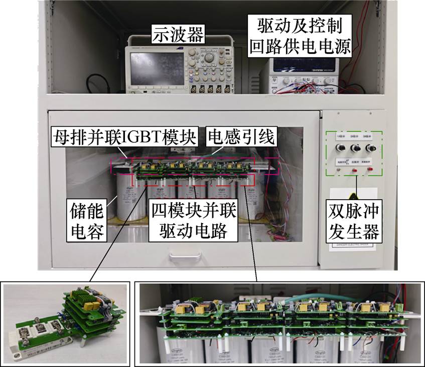
图9 驱动电路及IGBT模块实物连接示意图
Fig.9 Driving circuits and IGBT modules physical connection diagram
表2 并联双脉冲测试实验参数设置
Tab.2 Parallel double pulse test experimental parameter setting
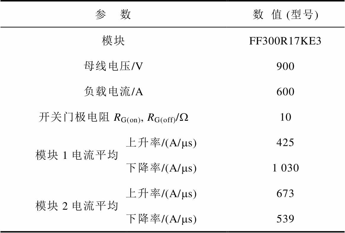
参 数数值 (型号) 模块FF300R17KE3 母线电压/V900 负载电流/A600 开关门极电阻RG(on), RG(off)/W10 模块1电流平均上升率/(A/ms)425 下降率/(A/ms)1 030 模块2电流平均上升率/(A/ms)673 下降率/(A/ms)539
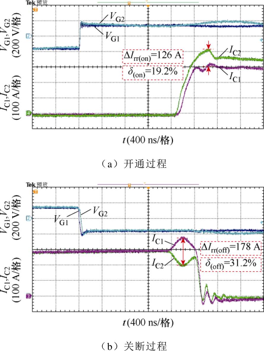
图10 普通驱动电压VG和集电极电流IC波形
Fig.10 The waveforms of the driving voltage VG and the collector current IC of the switching process
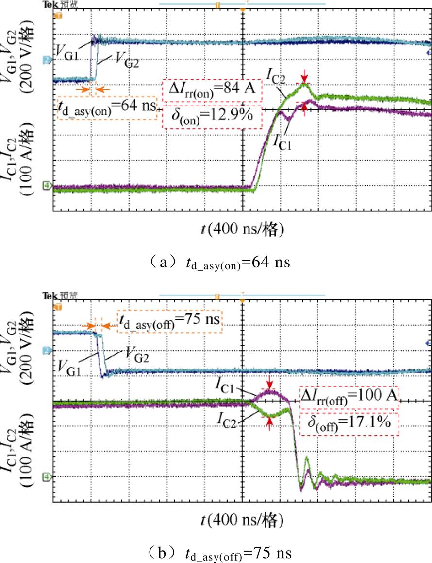
图11 异步间隙开关过程VG和IC波形
Fig.11 The waveforms of VG and IC of the switching process asynchronous gap control
开关过程驱动差压补偿前后VG和IC波形如图12所示。图12所示开关过程中,调整驱动差压和持续时间前后驱动电压VG和集电极电流IC波形。开关过程电流峰值总结见表3和表4。可以看出,驱动差压补偿在开通过程可以明显地降低开关过程集电极电流峰值,抑制电流过冲,而关断过程对电流过冲几乎没有抑制作用,与仿真结论相同。
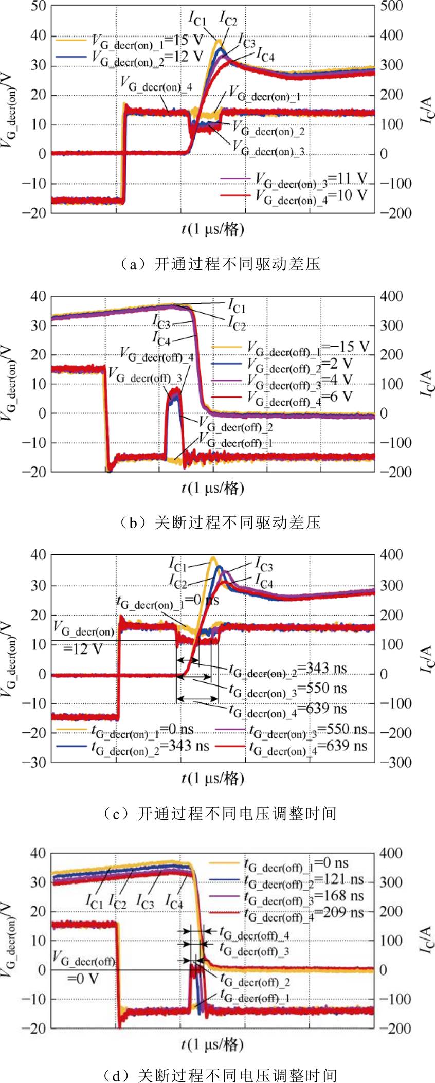
图12 开关过程驱动差压补偿前后VG和IC波形
Fig.12 The waveforms of VG and IC before and after voltage differential control in switching process
表3 驱动差压对集电极电流尖峰的抑制效果
Tab.3 The suppression effect of voltage differential on collector current overshoot
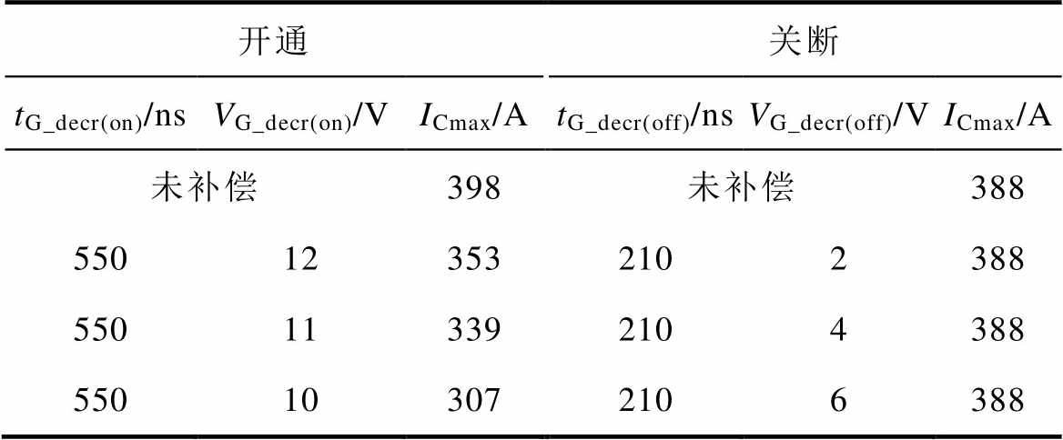
开通关断 tG_decr(on)/nsVG_decr(on)/VICmax/AtG_decr(off)/nsVG_decr(off)/VICmax/A 未补偿398未补偿388 550123532102388 550113392104388 550103072106388
表4 电压调整时间对集电极电流尖峰的抑制效果
Tab.4 The suppression effect of voltage adjustment time on collector current overshoot
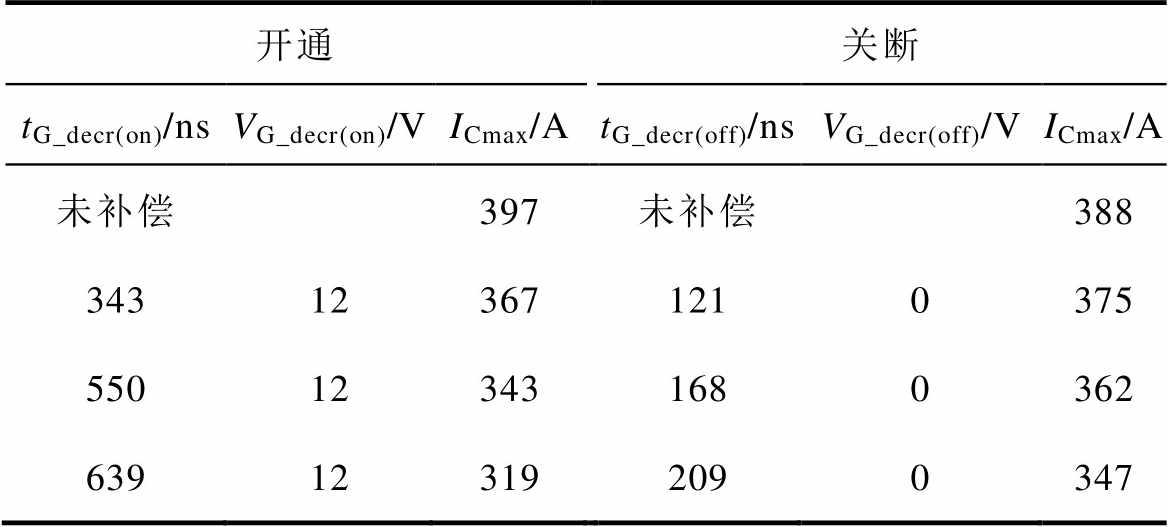
开通关断 tG_decr(on)/nsVG_decr(on)/VICmax/AtG_decr(off)/nsVG_decr(off)/VICmax/A 未补偿397未补偿388 343123671210375 550123431680362 639123192090347
选取不同驱动差压和电压调整时间分别进行实验,反映驱动差压对动态电流不均衡度的影响,实验结果如图13所示。图13a为驱动差压11 V,电压调整时间为245 ns,动态电流不均衡度降为7.2%,不均衡度改善因子达到了-12.0%;图13b为驱动差压-2 V,电压调整时间为309 ns,动态电流不均衡度升为53.9%,不均衡度改善因子达到22.7%,从实验结果可以看出,驱动差压控制对开通过程有较好的均流补偿效果,关断过程均流补偿效果不佳,该结论与仿真结果相同。
在母线电压600 V,负载电流1 200 A的工况下进行实验,测得图14所示四模块集电极电流及集射极电压波形。表5总结测量各支路集电极电流峰值等数据,并计算对应的动态电流斜率不均衡度。如图14所示,支路1关断过程电流较小,异步间隙为-120 ns,驱动差压为-2 V,电压调整时间为242 ns。补偿后会导致支路1的集电极电流下降率绝对值减小,造成支路1承受的关断电流过大,形成过补偿的情况。为避免这种情况发生,调整该支路的驱动信号异步间隙,使其早于其他支路关断,更早关断的支路会在关断过程分得较小的电流。支路2开通电流最小,仅为255 A,系因设定异步间隙使其较早开通。由于开通过程各支路电流差异小于关断过程,为避免过补偿现象发生,在对应支路电流上升过程中,降低一段时间的驱动电压,使该支路集电极电流上升率下降。根据上述分析,设定支路2异步间隙为-160 ns,驱动差压为12 V,电压调整时间为358 ns。
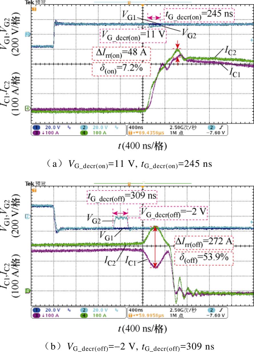
图13 引入驱动差压控制后开关过程驱动电压VG和集电极电流IC波形
Fig.13 The waveforms of the VG and IC in the switching process after the voltage differential control
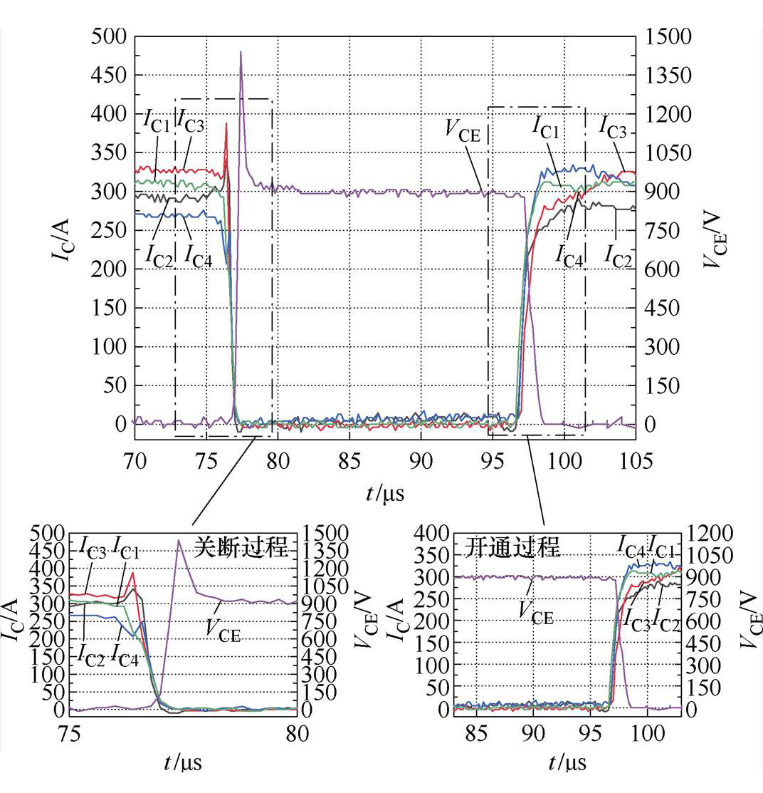
图14 四模块并联集电极电流及集射极电压波形
Fig.14 Four-module parallel VG and IC waveforms
表5 补偿前四模块并联实验结果
Tab.5 The experimental results of four modules in parallel before compensation
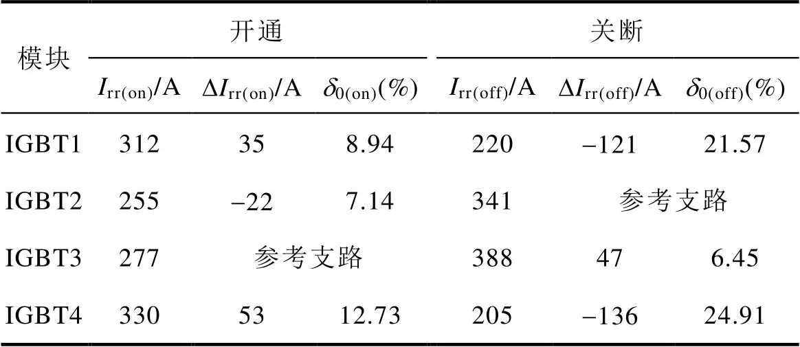
模块开通关断 Irr(on)/ADIrr(on)/Ad0(on)(%)Irr(off)/ADIrr(off)/Ad0(off)(%) IGBT1312358.94220-12121.57 IGBT2255-227.14341参考支路 IGBT3277参考支路388476.45 IGBT43305312.73205-13624.91
通过实行差压异步控制,在合理范围内增大支路2的开通电流。调整各支路异步间隙、驱动差压、电压调整时间后,得到如图15所示四模块门极驱动电压波形,以及如图16所示集电极电流和集射极电压波形,各支路集电极电流峰值差、动态电流斜率不均衡度等数据总结见表6。
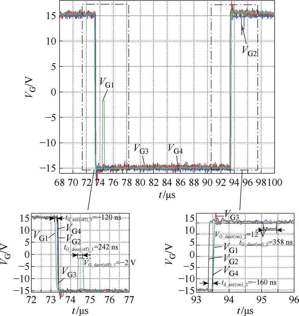
图15 四模块并联门极驱动电压波形
Fig.15 Four-module parallel gate drive voltage waveforms
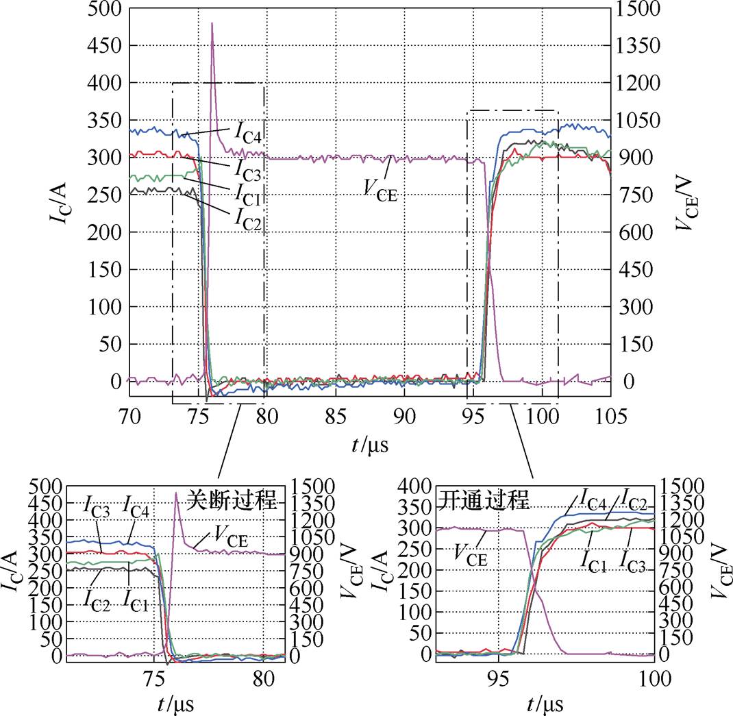
图16 差压异步补偿后集电极电流和集射极电压波形
Fig.16 The waveforms of VCE and IC after asynchronous differential amplitude drive
表6 补偿后四模块并联实验结果
Tab.6 The experimental results of four modules in parallel after compensation
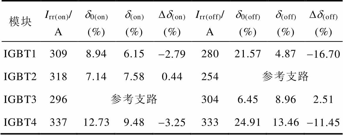
模块Irr(on)/ Ad0(on)(%)d(on)(%)Dd(on)(%)Irr(off)/ Ad0(off)(%)d(off)(%)Dd(off)(%) IGBT13098.946.15-2.7928021.574.87-16.70 IGBT23187.147.580.44254参考支路 IGBT3296参考支路3046.458.962.51 IGBT433712.739.48-3.2533324.9113.46-11.45
可以看出,经过差压异步驱动补偿后,开通过程支路1不均衡度降为6.15%,不均衡度改善因子为-2.79%,支路4不均衡度降为9.48%,不均衡度改善因子为-3.25%,不均衡度均降低;而支路2不均衡度为7.58%,不均衡度改善因子为0.44%,虽然支路2的不均衡度较补偿前增大了,但可看出整体不均衡度得到了明显改善。关断过程支路1不均衡度降为4.87%,不均衡度改善因子为-16.70%,支路4不均衡度降为13.46%,不均衡度改善因子为-11.45%,不均衡度均降低;支路3不均衡度升高为8.96%,不均衡度改善因子为2.51%,略有增大,但同样关断过程整体不均衡度明显降低。
本文研究了优化IGBT并联开关特性的差压异步驱动技术,主要包括以下内容:
1)进行差压异步驱动技术的理论分析,基于等效电流斜率的概念,推导出异步间隙、驱动差压、电压调整时间三个控制参数之间的协调关系,得到开关过程等效集电极电流斜率计算公式。
2)针对异步间隙和驱动差压对不均衡度改善因子影响进行研究,分析差压异步驱动控制优化参数设计方法,得到开关过程最优补偿范围,所选优化设计参数可明显优化并联动态均流问题。
3)在实际双脉冲测试电路中进行并联差压异步驱动方法实验,验证了该方法对开关过程动态均流特性的控制补偿效果。对四模块并联的驱动控制进行了实验分析,证明了差压异步驱动方法对于多模块并联系统动态特性的显著改善作用。
参考文献
[1] Lin Shuai, Fang Xiaochun, Lin Fei, et al. Lifetime prediction of IGBT modules based on mission profiles in traction inverter application[C]//2019 IEEE Vehicle Power and Propulsion Conference (VPPC), Hanoi, Vietnam, 2019: 1-6.
[2] 金肩舸, 杨进锋, 王晓元, 等. 高功率密度智能化集成功率器件及其并联应用研究[J]. 机车电传动, 2023(4): 145-151.
Jin Jiange, Yang Jinfeng, Wang Xiaoyuan, et al. Intelligent integrated power device with high power density and research on its parallel application[J]. Electric Drive for Locomotives, 2023(4): 145-151.
[3] 陈冲, 贾利民, 赵天宇, 等. 去碳化导向的轨道交通与新能源融合发展——形态模式、解决方案和使/赋能技术[J]. 电工技术学报, 2023, 38(12): 3321- 3337.
Chen Chong, Jia Limin, Zhao Tianyu, et al. Decar- bonization-oriented rail transportation and renewable energy integration development-configurations, solu- tions, and enabling/empowering technologies[J]. Transactions of China Electrotechnical Society, 2023, 38(12): 3321-3337.
[4] Li Jingyi, Wang Xiaohe, Lü Jing, et al. Stability analysis of wind farm connected to hybrid HVDC converter[C]//2020 IEEE 9th International Power Electronics and Motion Control Conference (IPEMC2020-ECCE Asia), Nanjing, China, 2020: 3258-3262.
[5] Chen Jianfu, Pei Xingyu, Wu Hongyuan, et al. Steady state characteristics of diode rectifier unit based grid-forming offshore wind power AC system[C]// 2022 5th International Conference on Power and Energy Applications (ICPEA), Guangzhou, China, 2022: 651-656.
[6] 范兴明, 李涛, 张鑫. 基于电容自然充电换相的混合式直流断路器设计与仿真[J]. 电工技术学报, 2024, 39(11): 3510-3521.
Fan Xingming, Li Tao, Zhang Xin. Design and simulation of hybrid DC circuit breaker based on capacitor natural charging commutation[J]. Transa- ctions of China Electrotechnical Society, 2024, 39(11): 3510-3521.
[7] 束洪春, 邵宗学, 旷宇. 基于改进型限流混合式直流断路器的开断时序优化研究[J]. 电工技术学报, 2023, 38(22): 6176-6187.
Shu Hongchun, Shao Zongxue, Kuang Yu. Research of opening timing optimization based on improved current-limiting hybrid DC circuit breaker[J]. Transa- ctions of China Electrotechnical Society, 2023, 38(22): 6176-6187.
[8] Liu Yixin, Huang Xianjin, Wang Fengchuan, et al. Research on the influence of current sharing characteristics under symmetrical power circuits layout for multi-module IGBTs parallel con- nection[C]//2021 23rd European Conference on Power Electronics and Applications (EPE'21 ECCE Europe), Ghent, Belgium, 2021: 1-8.
[9] 冯洪高, 张赤斌, 林宝德. 基于器件内部参数差异的大功率IGBT并联均流控制方法[J]. 电气传动, 2022, 52(6): 28-32.
Feng Honggao, Zhang Chibin, Lin Baode. Parallel current sharing control method of high power IGBT based on the difference of internal parameters[J]. Electric Drive, 2022, 52(6): 28-32.
[10] Chen Nan, Chimento F, Nawaz M, et al. Dynamic characterization of parallel-connected high-power IGBT modules[J]. IEEE Transactions on Industry Applications, 2015, 51(1): 539-546.
[11] Werner R, da Cunha J, Eckel H G. Mutual influence of quasistatic and dynamic current imbalances of paralleled IGBTs[C]//2019 21st European Conference on Power Electronics and Applications (EPE'19 ECCE Europe), Genova, Italy, 2019: 1-8.
[12] 曹子楷, 崔翔, 李学宝, 等. 压接型IGBT芯片的参数分散性对其并联时开通均流的影响[J]. 中国电机工程学报, 2023, 43(20): 8025-8037.
Cao Zikai, Cui Xiang, Li Xuebao, et al. Influence of parameter dispersion of pressure-bonded IGBT chips on current sharing when they are connected in parallel[J]. Proceedings of the CSEE, 2023, 43(20): 8025-8037.
[13] 彭程, 李学宝, 范迦羽, 等. 压接型IGBT器件内部杂散电感差异对瞬态电流分布影响规律研究[J]. 电工技术学报, 2023, 38(11): 2850-2860.
Peng Cheng, Li Xuebao, Fan Jiayu, et al. Study on the influence of stray inductance difference in IGBT devices on transient current distribution[J]. Transa- ctions of China Electrotechnical Society, 2023, 38(11): 2850-2860.
[14] 赵晨凯, 梁剑, 谢龙飞, 等. 适用于大功率IGBT并联的驱动技术研究[J]. 集成电路应用, 2022, 39(6): 1-3.
Zhao Chenkai, Liang Jian, Xie Longfei, et al. Study on parallel technology of high power IGBT drive[J]. Application of IC, 2022, 39(6): 1-3.
[15] 唐伟峰, 王长江. 功率器件的并联均流研究[J]. 电气传动, 2023, 53(3): 15-21.
Tang Weifeng, Wang Changjiang. Research on current sharing of parallel power devices[J]. Electric Drive, 2023, 53(3): 15-21.
[16] 穆峰, 刘宜鑫, 李鑫, 等. IGBT并联应用均流控制技术综述[J]. 电源学报, 2024, 22(1): 119-132.
Mu Feng, Liu Yixin, Li Xin, et al. Summary of current sharing control technology for IGBT parallel application[J]. Journal of Power Supply, 2024, 22(1): 119-132.
[17] Yu Jintao, Shao Lingfeng, Wei Weiwei, et al. A novel active gate drive for switching loss reduction of IGBT[C]//2023 IEEE PELS Students and Young Professionals Symposium (SYPS), Shanghai, China, 2023: 1-5.
[18] 王嘉智, 吴小涛, 刘福临, 等. 基于对偶原理的IGBT并联均流缓冲电路研究[J]. 中国电机工程学报, 2023, 43(10): 3962-3971.
Wang Jiazhi, Wu Xiaotao, Liu Fulin, et al. Research on current sharing snubber of parallel IGBTs based on duality principle[J]. Proceedings of the CSEE, 2023, 43(10): 3962-3971.
[19] Huang Xianjin, Mu Feng, Liu Yixin, et al. Asynchronous gate signal driving method for reducing current imbalance of paralleled IGBT modules caused by driving circuit parameter difference[J]. IEEE Access, 2021, 9: 86523-86534.
[20] 王风川. 基于敏感参数控制的栅极驱动技术研究[D]. 北京: 北京交通大学, 2022.
Wang Fengchuan. Research on gate driving tech- nology based on sensitive parameter control[D]. Beijing: Beijing Jiaotong University, 2022.
Abstract There is a growing demand for higher-capacity converters in large-scale energy storage and offshore wind power. The parallel application of IGBT (insulated gate bipolar transistor) modules has emerged as an effective strategy for enhancing converter capacity. This approach not only leverages the robustness and efficiency of IGBT technology but also allows for scalability in power conversion systems, keeping pace with the expanding requirements of modern energy infrastructure. Due to objective factors such as design, processing, and assembly, dynamic and static parasitic parameter differences exist between the branches of the parallel power circuit. In multi-module IGBT parallel operation, the branch current equalization characteristics affect the operating characteristics of the entire parallel system. Therefore, the main concern is improving the dynamic and static current equalization and the derating rate of IGBT modules.
The process variables in the form of current rise rate and current peak value at the moment of turn-on current affect the consistency of the switching process of multi-branch IGBTs. Based on the inherent parameter differences of parallel branch IGBT drive control loops, this paper proposes a parallel IGBT differential asynchronous drive technology. Adjusting the asynchronous gap of the drive pulses and changing the amplitude and duration of the drive voltage can drive the switching process current of IGBTs in each branch consistently. Hence, the control of IGBT gate pulses of different branches is coordinated. The effects of the drive signal asynchronous gap drive differential voltage and voltage adjustment time on the dynamic current slope unbalance during the switching process are investigated, and the control parameter coupling relationship is analyzed to optimize the parameter setting method. Based on the actual IGBT module parameters, a mathematical model of the device operating characteristics is established, and the parallel IGBT switching simulation and the actual working condition test are carried out. The results proved that the selected optimized design parameters can significantly improve the dynamic equalization of the switching characteristics of the parallel IGBT module, which verifies the feasibility of the optimized parameter design method.
This paper proposes differential voltage asynchronous drive technology for optimizing IGBT parallel switching characteristics. The following conclusions can be drawn.
(1) Differential voltage asynchronous drive technology is based on the concept of equivalent current slope. The consistency of the parallel branch current slope can be improved by coordinating the relationship between the three control parameters of the asynchronous gap, drive differential voltage, and voltage adjustment time.
(2) The optimal compensation range of the switching process is obtained, and the selected optimal design parameters can significantly optimize the shunt dynamic current uniformity problem.
(3) A double-pulse test platform is built to verify the proposed method’s control and compensation effects on dynamic equal-current characteristics during switching. The drive control of four parallel modules is analyzed, which proves the differential pressure asynchronous drive method significantly improves the dynamic characteristics of the multi-module parallel system.
keywords:Parallel IGBT, current sharing, driving voltage differential, asynchronous gap
DOI: 10.19595/j.cnki.1000-6753.tces.240999
中图分类号:TM46
知识产权许可项目(E24ZH200040)和中央高校基本科研业务费专项资金项目(E23JBZX00030)资助。
收稿日期 2024-06-11
改稿日期 2024-07-31
黄先进 男,1980年生,博士,副教授,博士生导师,研究方向为电能变换与储存、变流器控制技术、半导体器件驱动与保护。E-mail: xjhuang@bjtu.edu.cn(通信作者)
潘嘉琪 女,2001年生,硕士,研究方向为IGBT模块并联均流。E-mail: 23126332@bjtu.edu.cn
(编辑 陈 诚)