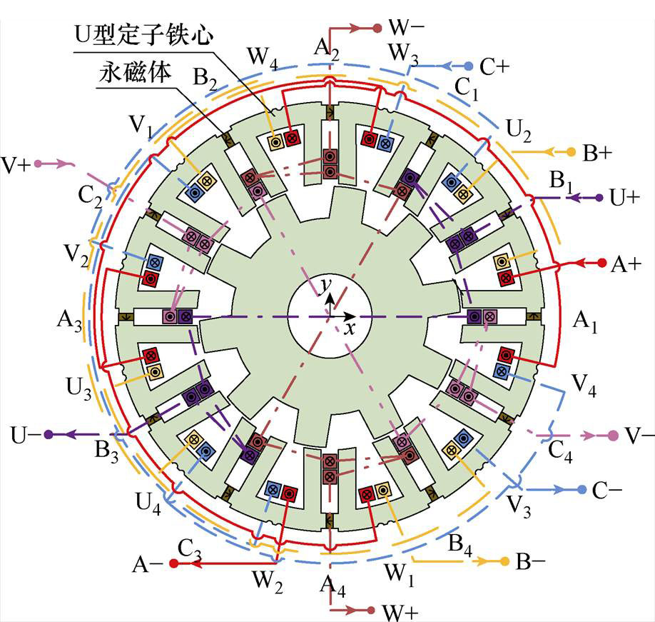
图1 BFSPMM结构示意图
Fig.1 The structure of BFSPMM
摘要 针对无轴承磁通切换电机非线性、多变量、强耦合特性,该文提出一种转子径向磁悬浮解耦控制策略。首先,采用最小二乘支持向量机的方法对悬浮力模型中的耦合电磁力部分进行拟合补偿,实现悬浮系统初步解耦;然后,验证悬浮系统可逆性,并按照逆系统理论设计伪线性复合悬浮系统,进一步实现了悬浮系统的线性化解耦;最后,对解耦后的悬浮系统设计闭环控制器,对悬浮闭环系统稳定性进行理论分析。实验结果验证,所提控制策略实现了无轴承磁通切换电机悬浮系统的动态解耦,提升了悬浮系统的动、静态性能。
关键词:无轴承磁通切换电机 逆系统 最小二乘支持向量机 径向磁悬浮 解耦控制
无轴承磁通切换电机(Bearingless Flux- Switching Permanent Magnet Machines, BFSPMM)是一种将传统磁通切换电机与磁轴承技术相结合的新型电机[1],既具有传统磁通切换电机转子结构简单、适宜高速运行等特点[2],又具有磁轴承电机无机械摩擦、无需润滑等优点[3-5]。BFSPMM特殊的定子永磁型结构使其具有良好的散热性能,永磁体温升退磁的风险低[6-7],在医药制造、航空航天、化学化工等要求高温、高速、无污染的场合具有广泛的应用前景[8-10]。
BFSPMM定子上的悬浮绕组与转矩绕组分别控制电机悬浮与旋转。两套绕组的自感与互感磁链、永磁体磁链共同构成了电机内部相互耦合的磁场,使BFSPMM具有非线性、多变量、强耦合的磁场分布特点。因此,悬浮系统解耦控制策略的构建成为提高电机磁悬浮性能的关键。
逆系统解耦控制方法易于理解与分析,在非线性系统的解耦控制领域中有着广泛的应用[11-12]。例如,文献[13]在实现无轴承异步电机逆系统解耦的情况下,设计相应内模控制器,提高了系统的鲁棒性能。文献[14]提出一种基于逆系统解耦的改进型二自由度控制方法,用速度观测器代替速度微分,降低了噪声对电磁轴承飞轮转子系统的影响,实现了飞轮转子的稳定悬浮控制。但此类方法对于电机数学模型的依赖程度较高,因此构建更加精确的数学模型,是实现高性能逆系统解耦控制的关键。
尽管现有BFSPMM转子悬浮力建模方案[15-18]能完成悬浮力解析模型的构建,但未能充分考虑悬浮绕组自感、悬浮绕组受转矩绕组互感以及转子角度对于悬浮力的耦合影响。目前,各类解析建模方案虽然能在不同程度上还原电机的电磁特性,但针对具有强耦合特性的BFSPMM悬浮力全模型的解析建模方案未见报道。
近年来,智能算法在非线性时变系统建模中受到了越来越多的关注[19-20]。例如,文献[21]利用卷积神经网络构建了永磁同步电机的转矩与温度模型,实现了较高精度的转矩与温度预测。文献[22]应用粒子群优化的递归神经网络来观测开关磁阻电机的定子磁链,相比于传统的递归神经网络提高了收敛速度与辨识精度。但神经网络存在学习速度慢、局部极小问题以及训练时间长等缺点。为克服神经网络的缺点,文献[23]应用泛化能力更强的最小二乘支持向量机(Least Squares Support Vector Machine, LSSVM)构建了无轴承感应电机磁链的模型,准确反映了电机的实际磁链特性。文献[24]在传统单输出结构LSSVM开关磁阻电机建模方法上加以改进,提出一种多输入多输出LSSVM结构,避免传统方法造成的累计误差,提高了模型的准确性。由于良好的非线性逼近能力与训练效率,LSSVM也被广泛应用于无轴承电机的逆系统模型构建中。如文献[25]利用LSSVM训练无轴承同步磁阻电机逆系统模型,相比传统解析逆系统模型具有更高精度,提高了系统的动、静态性能。文献[26]基于改进遗传算法寻优LSSVM的性能参数,避免了训练过程中的过学习问题,实现了外转子无铁心无轴承永磁同步发电机精确控制。但要实现高精度全逆系统模型的构建对LSSVM的训练程度要求高。
本文针对BFSPMM气隙磁场强耦合、非线性所致的悬浮力解析建模获取困难的问题,提出一种通过结合已知部分悬浮力解析系统模型,LSSVM拟合未建模部分的逆系统控制策略。首先,分析了转子径向位移受到陀螺效应力、悬浮力中耦合电磁力的耦合作用。其次,利用LSSVM构建悬浮力耦合电磁力预测模型,并根据耦合电磁力预测值进行补偿。然后,根据逆系统理论搭建悬浮系统伪线性系统,实现BFSPMM悬浮系统的进一步解耦控制。最后,通过仿真和实验验证所提控制策略的性能。
本文所研究的BFSPMM结构如图1所示。

图1 BFSPMM结构示意图
Fig.1 The structure of BFSPMM
BFSPMM定子部分绕有三相转矩绕组(A, B, C)与三相悬浮绕组(U, V, W),三相绕组轴线空间上分别相差120°,A相转矩绕组滞后U相悬浮绕组30°。相邻的U型定子铁心中放置有切向充磁的永磁体。在BFSPMM中,永磁体产生气隙偏置磁场,转矩绕组和悬浮绕组产生气隙调制磁场,从而分别产生洛伦磁力和麦克斯韦力,进而实现转子的旋转与悬浮控制[15]。
为分析方便,转矩及悬浮平面坐标系定义如图2所示。
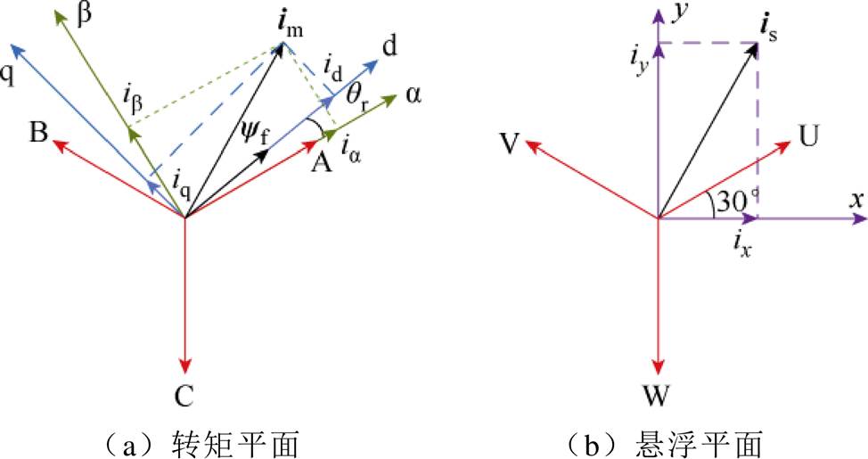
图2 转矩及悬浮平面坐标系定义示意图
Fig.2 Coordinate system definition of torque and suspension plane
图2a转矩平面中, 为静止直角坐标系,以A相绕组轴线方向定义为
 轴;dq为同步旋转坐标,d轴与三相转矩绕组耦合的永磁体磁链合成矢量
 方向相同。d轴与
 轴夹角为转子旋转电角度
 ;三相转矩绕组电流合成矢量
 在各坐标轴上投影用下标标注。
图2b悬浮平面中,滞后U相绕组轴线30°方向定义为x轴,y轴超前x轴90°。x、y轴分别对应图1中A1、A2线圈轴线。三相悬浮绕组电流合成矢量 在各坐标轴上投影用下标标注。
文献[27]研究结果表明,该电机可以忽略凸极效应,电机的电磁转矩可表示为
 (1)
(1)
式中, 为电机的极对数;iq为转矩绕组电流q轴分量。
由式(1)可知,通过控制iq即可控制电磁转矩。
本文所研究的BFSPMM转子系统基本结构如图3所示。转子系统主要由转子铁心、自调心球轴承、保护轴承、转子铁心附属件等部分组成。转子位置信息由电涡流传感器实时测量。
图3中,转子铁心重心为 ,几何中心为c,
 、
、 、
、 分别为球轴承到重心
 、几何中心c和径向位移传感器的距离,mg为转子的重力,
 为转子转速。
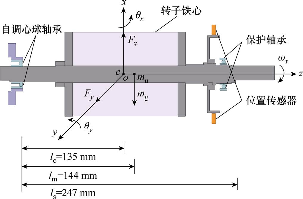
图3 转子结构示意图
Fig.3 The structure of the rotor
为便于分析,以未偏心下的理想几何中心点c为坐标原点o构建如图3所示oxyz坐标系,x、y轴与图2所示悬浮平面x、y轴重合。 、
、 分别为x、y方向的转子径向位移投影,
 、
、 分别为绕x、y方向转动的转子角位移,
 、
、 分别为x、y方向上转子所受悬浮力的分量。在忽略转子外阻尼情况下,根据转子动力学原理,转子运动方程可表示为
 (2)
(2)
式中, 为赤道转动惯量;
 为极转动惯量。
由式(2)可知,转子x、y方向角位移由于陀螺效应项 、
、 相互耦合,且耦合作用与转速呈线性关系。
转子径向位移 、
、 满足
满足
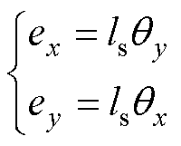 (3)
(3)
当采用转矩平面d轴电流给定 控制,电机在运行时的转子所受悬浮力表达式为
 (4)
(4)
式中, 、
、 分别为悬浮绕组电流
 、
、 在x、y方向产生的电磁力;
 、
、 分别为
分别为 、
、 在x、y方向产生的耦合电磁力;
 、
、 分别为
分别为 、
、 在x、y方向产生的偏心磁拉力;
 、
、 分别为
分别为 、
、 在x、y方向产生的耦合电磁力;
 、
、 分别为两套绕组磁耦合在x、y方向产生的耦合电磁力。
由式(4)可知,BFSPMM悬浮力具有强耦合特性,耦合电磁力与悬浮绕组电流、转矩绕组电流、径向位移、转子位置角有关。x、y方向耦合电磁合力 、
、 为
为
 (5)
(5)
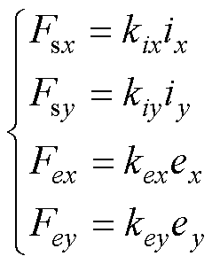
忽略非线性因素影响,悬浮力中未耦合电磁力各部分表达式为
 (6)
(6)
结合式(5)、式(6),式(4)可进一步表示为
 (7)
(7)
式中, 、
、 分别为x、y方向的力-电流系数;
 、
、 分别为x、y方向的力-位移系数。
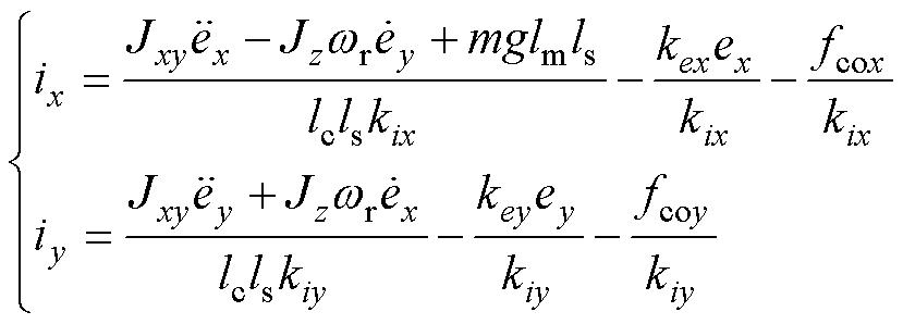
结合式(3)、式(7),式(2)可进一步表示为
 (8)
(8)
由于无法准确得到BFSPMM转子悬浮力中耦合电磁力部分的解析模型,使得逆系统解耦控制方法难以取得理想的效果。LSSVM具有优秀的非线性函数拟合逼近能力,因此本节使用LSSVM对耦合电磁力进行预测。
由式(5)可知,转子悬浮力中x、y方向耦合电磁力 、
、 分别是关于
分别是关于 和
和 的非线性函数。因此在获取训练样本时,令
 为样本输入,
 为样本输出。对BFSPMM有限元模型施加限幅范围内的随机电流激励
 、
、 、
、 ,以获得在不同转子位置角、径向位移下的1 000组运行数据集,其中
 限幅为6 A,
 、
、 限幅为3 A。有限元模型无法直接得到耦合电磁力
 、
、 ,通过式(7)计算得到
 (9)
(9)
取80%运行数据集为训练集,其余20%作为测试集,选取LSSVM的两个参数惩罚因子倒数
 ,核宽度二次方
 。LSSVM的训练原理与拟合结构如图4所示。
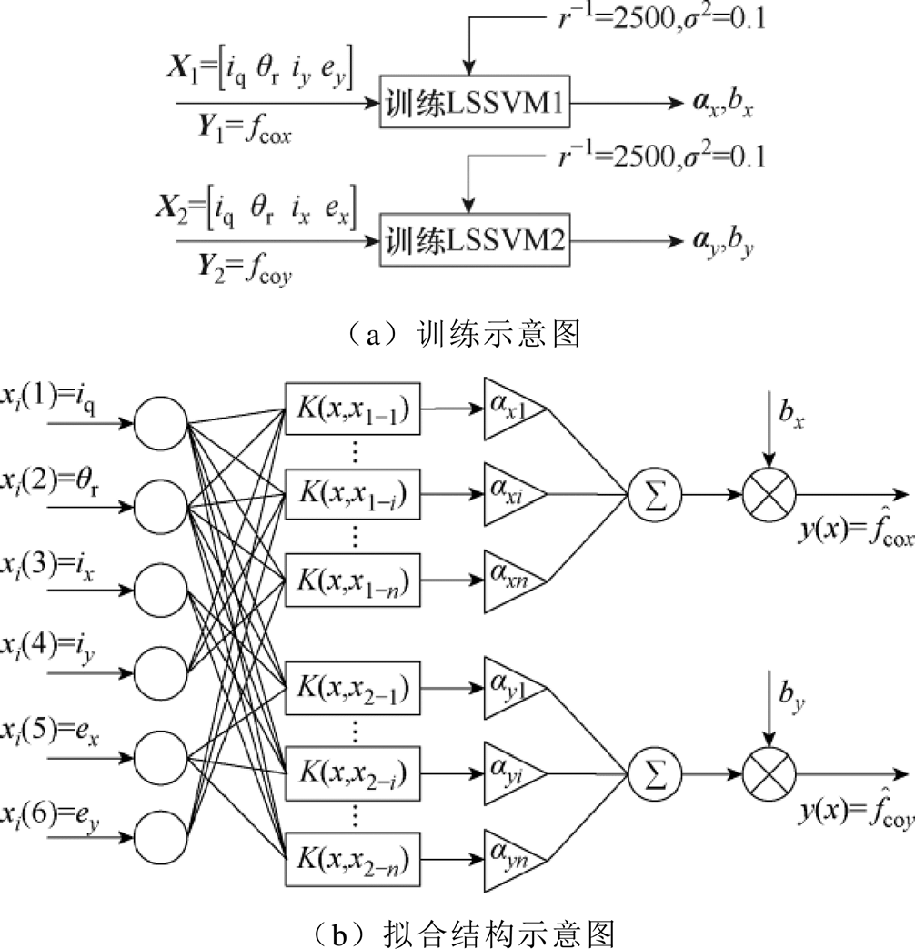
图4 LSSVM原理
Fig.4 The schematic diagram of LSSVM
由图4a可见,分别训练LSSVM1、LSSVM2拟合x、y方向耦合电磁力 、
、 。以拟合
。以拟合 为例,取样本输入X的子集
 与样本输出Y的子集
 用以训练LSSVM1,拉格朗日算子
 与偏置
与偏置 满足
满足
 (10)
(10)
式中, 为n×1矩阵,n为训练样本数量;I为n维单位矩阵;
 ;子集Y1第i组数据为y1_i,则
 ,i、j
,i、j N*且i、j
 n;
n; 为n×n对称矩阵,其第i行第j个元素
 表达式为
表达式为
 (11)
(11)
式中,x1_i为子集X1的第i组数据; 为核函数,本文选择径向基函数作为核函数。
图4b可见,向训练好的LSSVM输入相应变量,经过径向基核函数计算后,与式(10)得到的拉格朗日算子 相乘,最后加上偏置
 即可得到耦合电磁力预测值
 、
、 。
。
为验证拟合效果,将测试集中耦合电磁力的实际值与LSSVM的预测值做差得到拟合误差,如图5所示。由图5可见,x、y方向的耦合电磁力拟合误差较小,验证了所构建的LSSVM耦合电磁力预测模型的准确性。
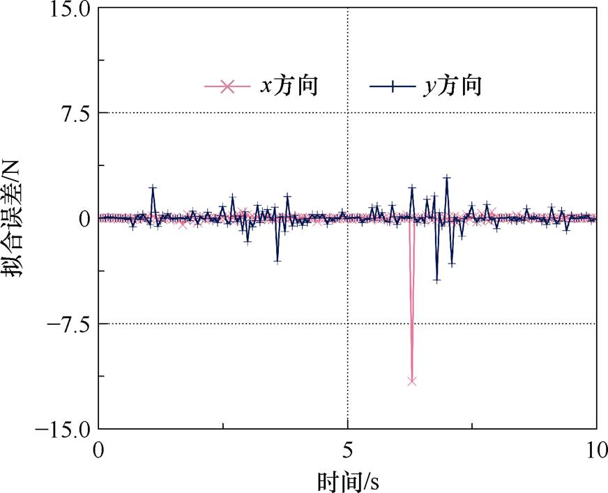
图5 LSSVM电磁力拟合误差
Fig.5 The diagram of electromagnetic force fitting error of LSSVM
采集电机加速运行过程中的电流、位移等信号,将信号通过有限元仿真模型计算得到转子在x、y方向上的耦合电磁力,与LSSVM拟合的耦合电磁力对比如图6所示。由图6可见,LSSVM的拟合值能较好地贴近有限元仿真值,进一步验证了预测模型的准确性。
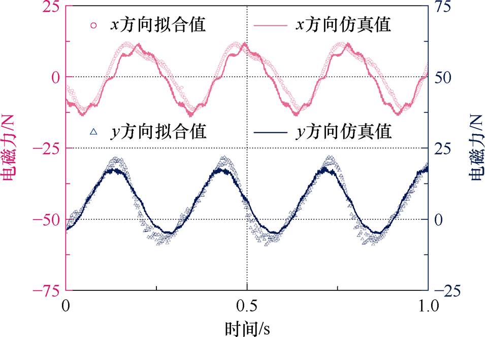
图6 沿x、y方向耦合电磁力
Fig.6 Coupling the electromagnetic force along the x and y directions
由式(5)和式(7)可知,耦合电磁力的存在不仅令转子x、y方向悬浮力受到 、
、 的影响,还受到不同方向径向位移、悬浮电流的耦合影响。为实现更高性能转子径向磁悬浮,需要对悬浮力进行解耦。
将悬浮电流重构为
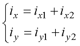 (12)
(12)
式中, 、
、 为悬浮电流中可控分量;
 、
、 为补偿耦合电磁力的悬浮电流分量。
基于重构后的悬浮电流,式(8)可拆分为
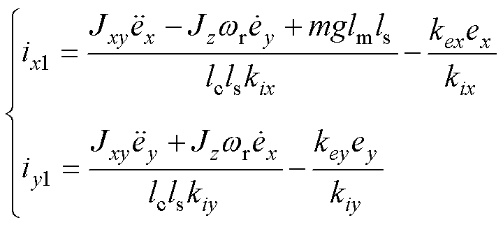 (13)
(13)
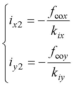 (14)
(14)
其中,式(13)为陀螺效应耦合部分的转子运动方程,式(14)为电磁力耦合部分。
式(8)、式(14)关系进一步用结构框图表示,如图7中左图所示。

图7 耦合电磁力非线性补偿后的转子运动学系统
Fig.7 Rotor motion system with nonlinear compensation of coupling electromagnetic force
实际系统中真实的耦合电磁力 、
、 无法获得,本文利用2.1节中预测值
 、
、 替代实际值来获得耦合电磁力补偿电流分量
 、
、 ,如图7中右图所示。这样就可利用
 、
、 悬浮电流可控分量实现转子x、y径向位移的线性控制。
上文对耦合电磁力进行补偿,实现了转子磁悬浮模型的初步线性化解耦,但转子径向位移仍存在陀螺效应的耦合。本节采用逆系统方法对陀螺效应耦合部分的悬浮系统进一步非线性解耦,最终实现BFSPMM转子悬浮系统的完全解耦。
在逆系统解耦前,首先要对系统可逆性进行分析。选取BFSPMM复合被控对象的状态变量为
 (15)
(15)
输入变量为
 (16)
(16)
输出变量为
 (17)
(17)
由式(13)可得陀螺效应耦合部分悬浮系统状态方程为
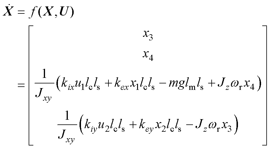 (18)
(18)
系统输出方程为
 (19)
(19)
对输出变量Y的各个部分求导,直至得到显含输入变量U的表达式。
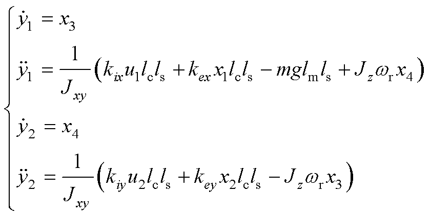 (20)
(20)
记 ,其Jacbian矩阵为
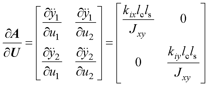 (21)
(21)
因为 ,
, 不为0,故
不为0,故 ;
; 、
、 导数的最低阶次分别为2、2,所以系统相对阶数
 (n1为状态变量个数,n1=4),满足可逆性条件,系统可逆。
选取逆系统的输入变量为
 (22)
(22)
由式(18)可得该部分悬浮系统逆系统表达式为
 (23)
(23)
将求解得到的逆系统串联到原系统之前,即可将原系统解耦成两个独立的二阶积分型伪线性系统,如图8所示。图8中, 、
、 为悬浮电流可控分量给定电流,
 、
、 为补偿耦合电磁力的给定电流。

图8 伪线性复合系统
Fig.8 The pseudo linear composite system
由于实际电机的数学模型并不完全准确,所得到的伪线性复合系统不是一个理想的线性系统,本文对线性化解耦后的伪线性系统设计PID闭环控制器如图9所示,图中, 为系统输入,
 为参考输出。控制器传递函数为
 (24)
(24)

图9 闭环控制系统框图
Fig.9 Block diagram of a closed-loop control system
式中, 为比例系数;
 、
、 分别为积分、微分时间常数。
以x方向为例,假设模型准确,则伪线性子系统的传递函数为
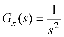 (25)
(25)
则输入 到输出
到输出 的闭环传递函数为
 (26)
(26)
将式(24)、式(25)代入式(26),可得
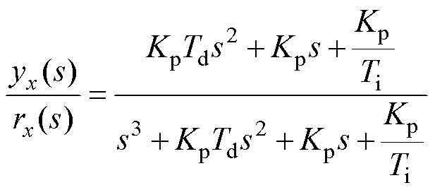 (27)
(27)
由劳斯判据可得,控制器稳定的充要条件为
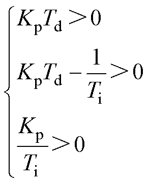 (28)
(28)
由于 、
、 、
、 均大于零,寻找合适的控制器参数使之满足
 ,闭环系统即为稳定。
综上所述,本文所提BFSPMM转子径向磁悬浮解耦控制框图如图10所示。
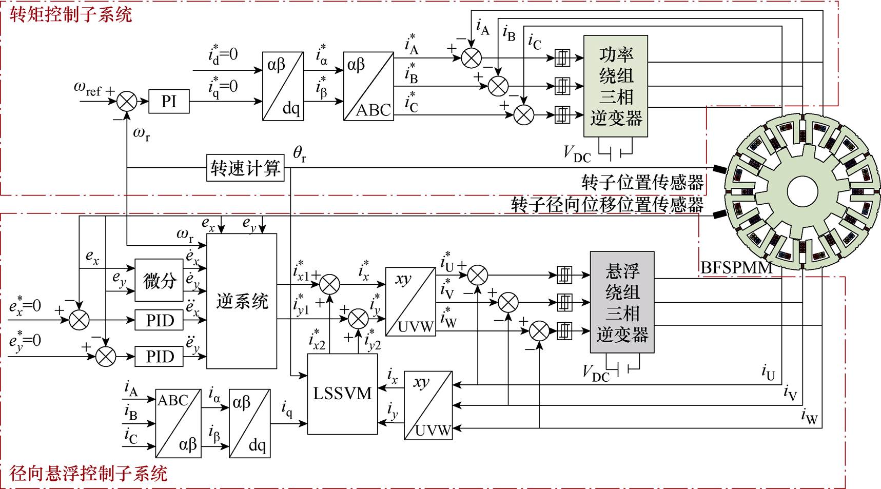
图10 系统控制框图
Fig.10 Block diagram of system control strategy
为验证所提出转子悬浮控制策略的可行性,对该控制系统进行仿真分析。设置电机给定转速1 500 r/min,带4 N·m转矩,对所提悬浮控制策略和传统PID悬浮控制策略进行对比仿真。
图11为转子启浮时,两种控制策略的径向位移,未悬浮时转子受重力影响处于x=-0.3 mm处。由图11可见,所提控制策略的转子径向位移超调量较PID控制更小,系统稳定性更佳。
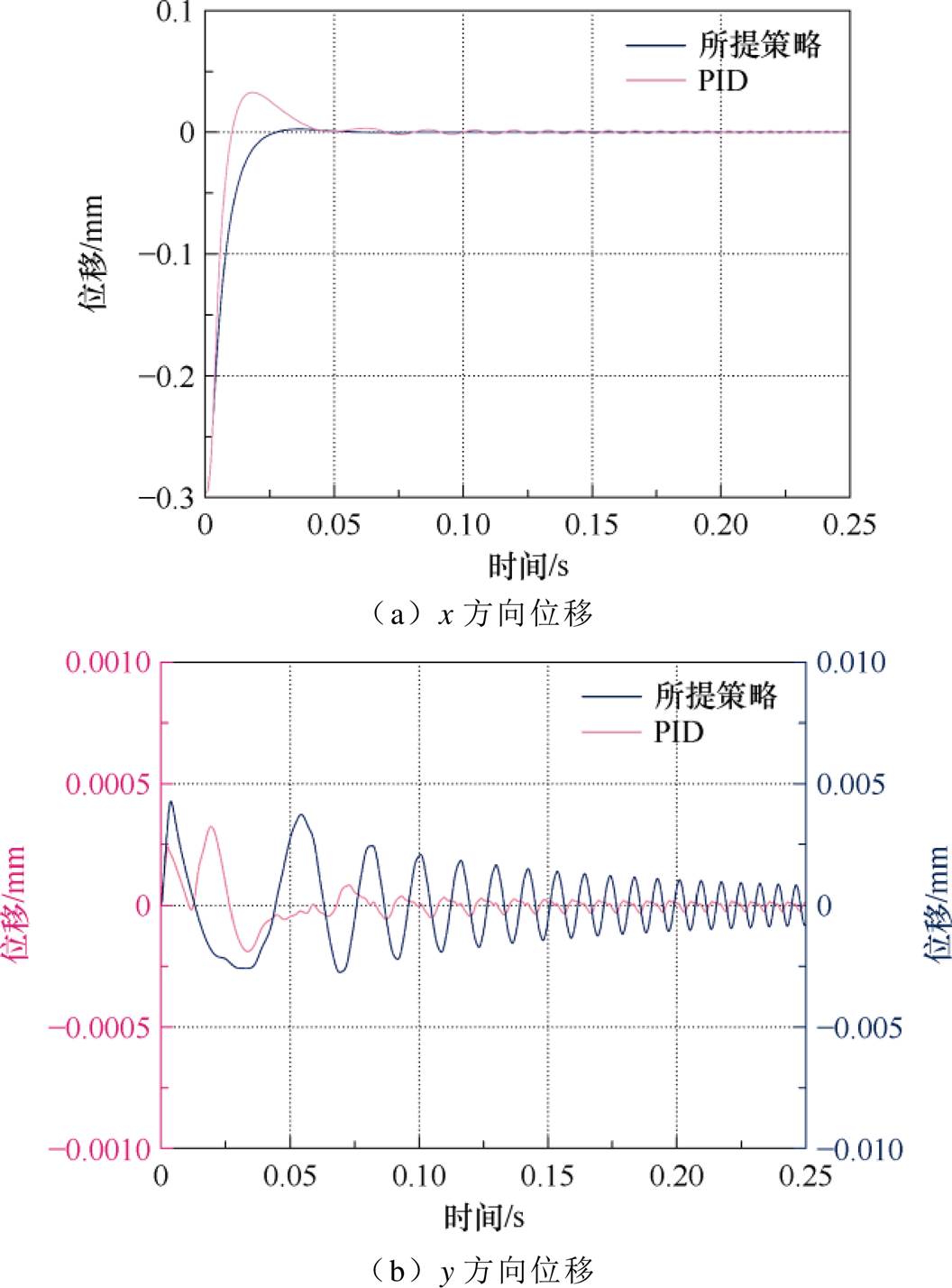
图11 启浮时转子径向位移
Fig.11 Rotor radial displacement during suspensing
图12为悬浮负载变化时两种控制策略下的转子径向位移。在0.1 s时同时向转子施加x方向、y方向各50 N负载,在0.3 s时撤去负载。在负载变化时,PID控制策略下的转子均产生了较大幅值的径向位移波动,最大值有0.023 mm,相较而言,所提控制策略转子位移几乎不受影响。仿真结果可见,所提控制策略下转子悬浮系统动态性能得以提升。
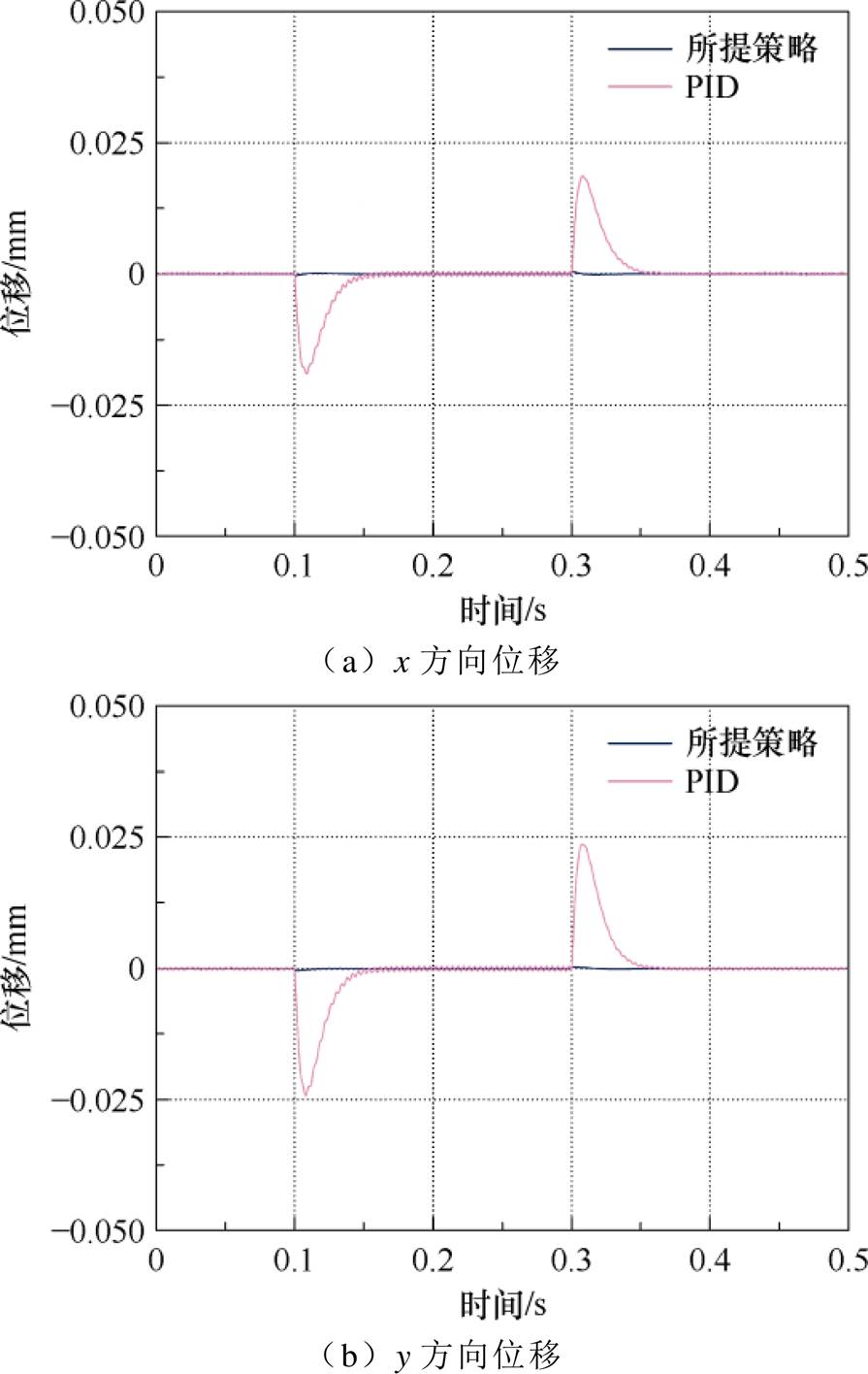
图12 悬浮负载变化下转子径向位移
Fig.12 Rotor radial displacement under suspension load change
为验证所提控制策略的解耦性能,以BFSPMM实验样机为被控对象进行实验验证。控制电路核心芯片为TMS320F28377D;转子位置传感器采用光洋TRD2T2500AF增量式光电编码器,该编码器允许的最高机械转速为5 000 r/min,输出频率为200 kHz;径向位置传感器采用株洲六零八航空发动机研究所TR81系列分体式电涡流位移传感器,其检测精度为20 mm。BFSPMM样机主要参数见表1,
表1 BFSPMM主要参数
Tab.1 The main specifications of BFSPMM
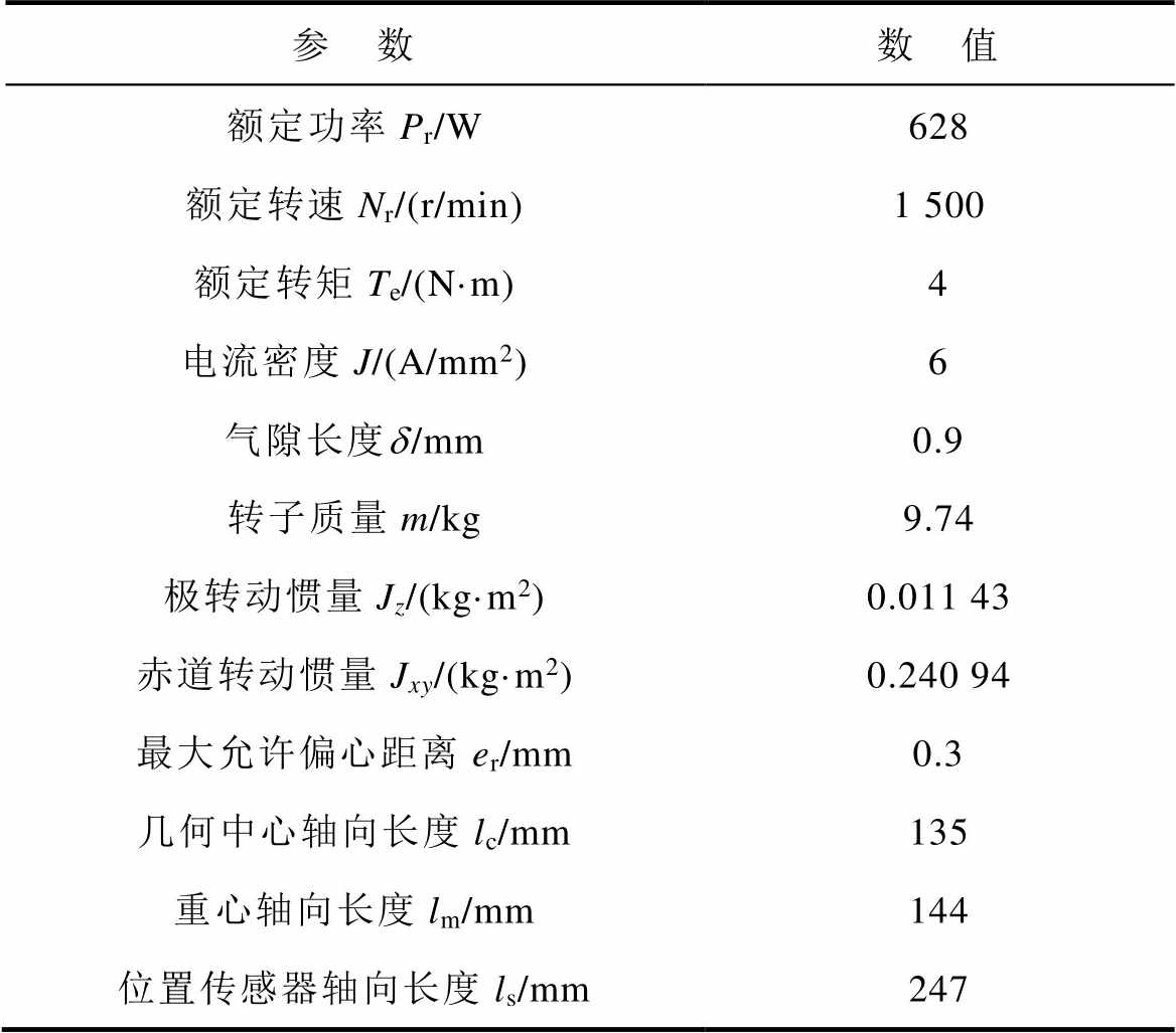
参 数数 值 额定功率Pr/W628 额定转速Nr/(r/min)1 500 额定转矩Te/(N·m)4 电流密度J/(A/mm2)6 气隙长度d/mm0.9 转子质量m/kg9.74 极转动惯量Jz/(kg·m2)0.011 43 赤道转动惯量Jxy/(kg·m2)0.240 94 最大允许偏心距离er/mm0.3 几何中心轴向长度lc/mm135 重心轴向长度lm/mm144 位置传感器轴向长度ls/mm247
电机实验平台如图13所示。
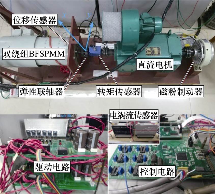
图13 BFSPMM实验平台
Fig.13 BFSPMM experimental platform
为验证所提出控制策略的有效性,选取转子悬浮PID控制策略作为对比,电机以1 500 r/min,带4 N·m转矩的额定工况运行,转子径向位移如图14所示。
图14可见,所提出控制策略的径向位移控制在0.054 mm以内,而PID控制的径向位移在0.12 mm范围内波动,所提出的控制策略径向位移约为PID控制的45.0%。实验结果验证了所提出的控制策略具有更好的稳态性能。
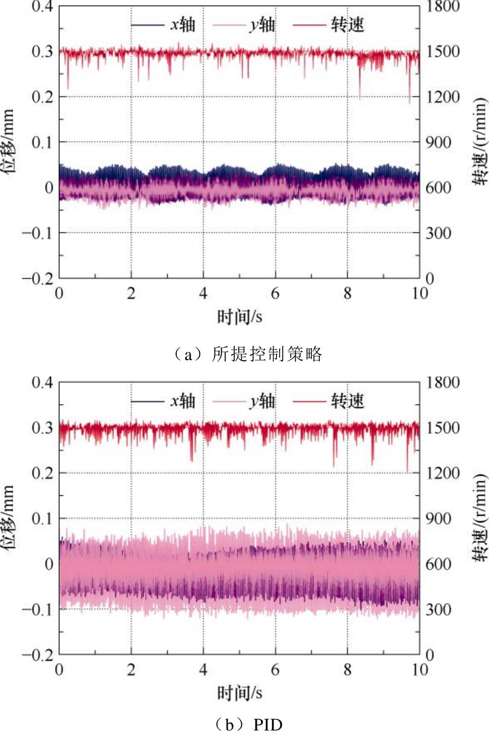
图14 额定工况稳态性能对比
Fig.14 Comparison of steady-state performance under rated operating conditions
控制器参数与相应闭环控制带宽见表2。上述PID控制策略的参数见表2中第一组,由于x、y方向具有一致性,选择相同参数。为进一步研究不同PID控制带宽对转子径向位移的影响,选取更高控制带宽下的两组参数进行实验,转子偏心位移如图15所示。
表2 控制器参数与相应闭环控制带宽
Tab.2 Controller parameters and corresponding closed-loop control bandwidth
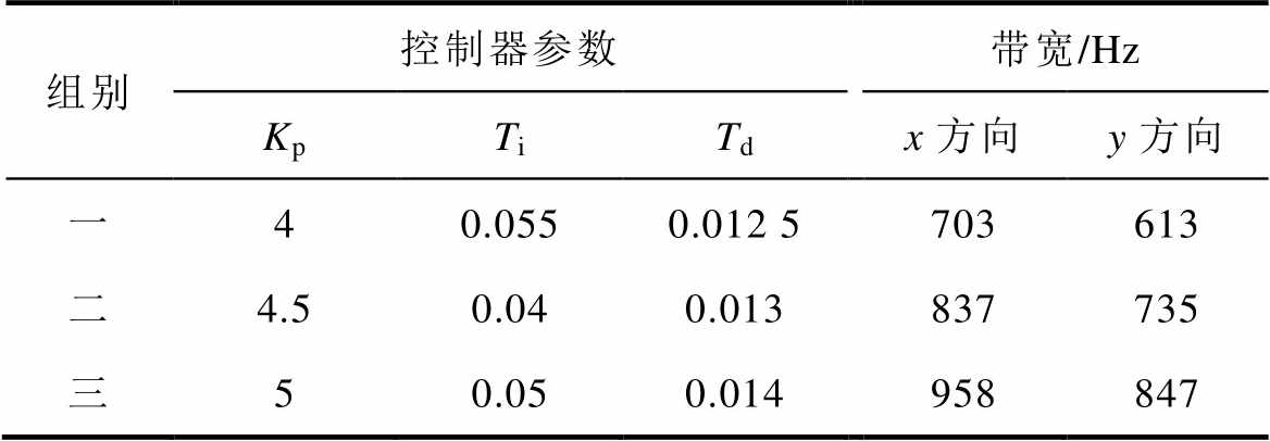
组别控制器参数带宽/Hz KpTiTdx方向y方向 一40.0550.012 5703613 二4.50.040.013837735 三50.050.014958847
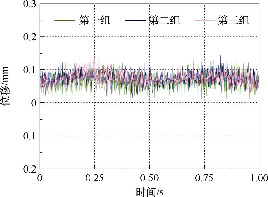
图15 不同控制带宽下偏心位移
Fig.15 Eccentric displacement at different control bandwidths
图15中,第一组、第二组、第三组的转子平均偏心位移分别为0.068、0.073、0.076 mm,更高的控制带宽并未改善转子的位移波动,故实验中选用第一组控制器参数进行转子悬浮PID控制。
为验证所提控制策略的解耦性能,在电机以1 500 r/min带4 N·m转矩运行时对其突加干扰,转子径向位移变化如图16所示。
图16a可见,当对x轴突加干扰时,x轴方向的径向位移产生0.15 mm的扰动,而y轴几乎不受影响;图16b可见,当对y轴突加干扰时,y轴方向的径向位移产生0.13 mm的扰动,而x轴几乎不受影响;实验结果证明了所提控制策略具有良好的动态解耦性能与抗干扰能力。
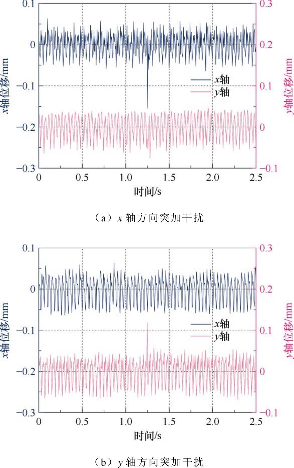
图16 突加干扰实验
Fig.16 Sudden interference force experiment
图17a为BFSPMM在不同转速下带4 N·m转矩的转子径向位移波形。由图17a可见,在不同转速下转子的偏心位移最大为0.076 mm,小于最大所允许的偏心位移0.3 mm,电机正常悬浮。图17b为BFSPMM在1 500 r/min转速下带不同转矩的转子径向位移波形。由图17b可见,随着转矩的增加,转子径向位移均控制在0.055 mm以内,偏心位移控制在0.069 mm以内。实验结果证明了所提控制策略具有良好的解耦性能。
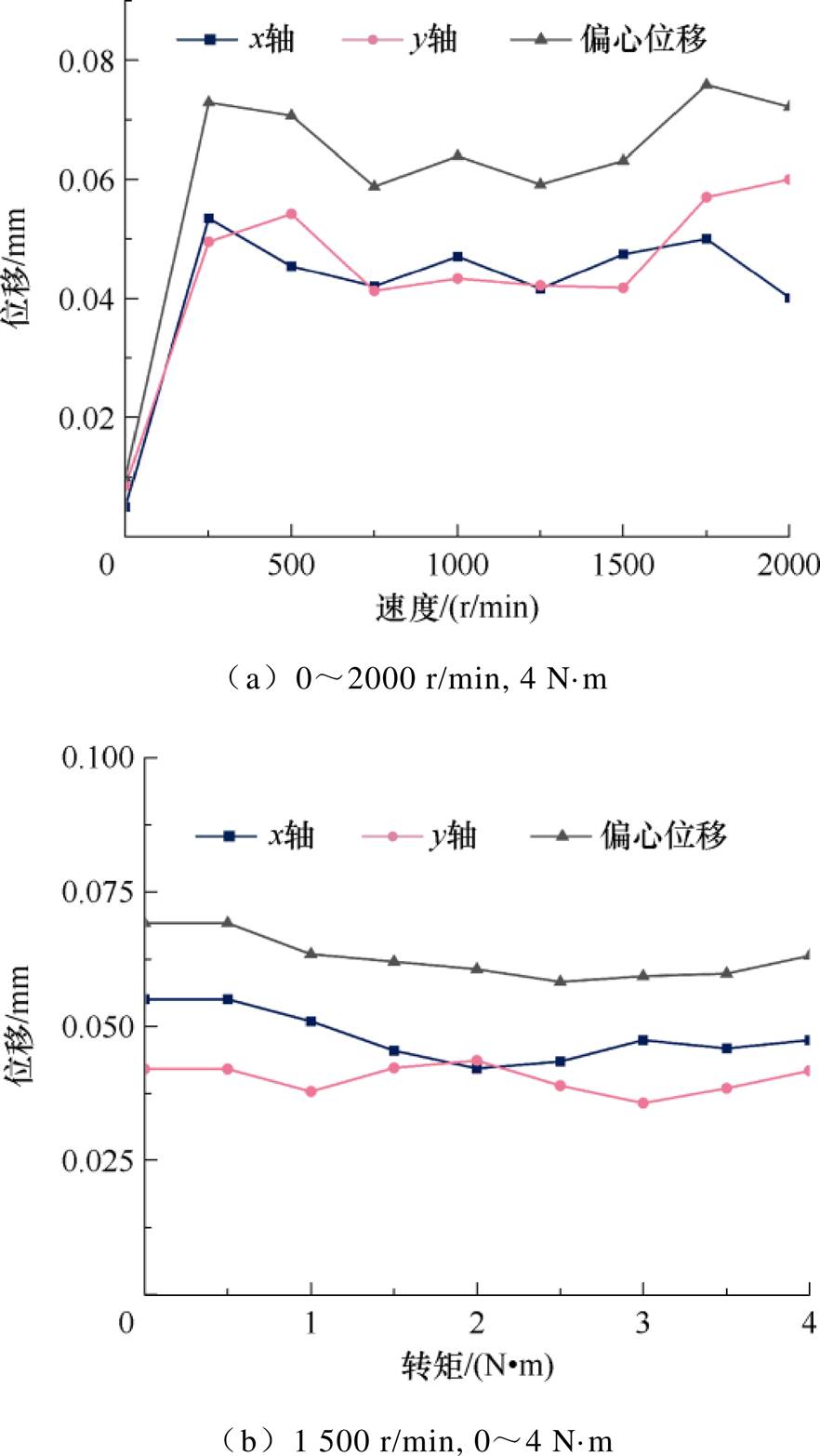
图17 不同工况实验波形
Fig.17 Experimental waveforms under different working conditions
图18为BFSPMM的转速变化实验波形。在2.5 s左右,令BFSPMM的转速给定从1 000 r/min阶跃至1 500 r/min,13.5 s左右阶降至1 000 r/min。由图18可见,转速变化时,径向位移受影响而增加,最大径向位移约为0.08 mm,而后降低并控制在0.05 mm以内,验证了转速变化情况下所提出的控制策略的稳定性。
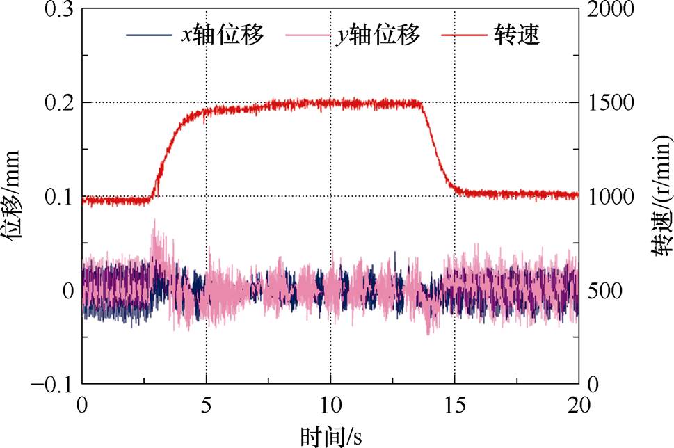
图18 转速变化实验波形
Fig.18 Rotational speed change experiment waveforms
本文针对BFSPMM转子磁悬浮提出了一种基于LSSVM解耦的逆系统控制,并进行了理论分析与仿真实验,得到如下结论:
1)利用LSSVM构建悬浮力耦合电磁力预测模型,并补偿耦合电磁力到悬浮系统中,初步实现了悬浮系统的线性化解耦。
2)逆系统进一步实现了悬浮系统的解耦控制,转子径向位移脉动大幅度减小,且具有良好的动态解耦性能。
参考文献
[1] 王晓琳, 倪拓成, 丁强, 等. 一种新型无轴承磁通切换电机原理及其实现[J]. 中国电机工程学报, 2017, 37(12): 3612-3620, 3690.
Wang Xiaolin, Ni Tuocheng, Ding Qiang, et al. Principle and implementation of a novel bearingless flux-switching motor[J]. Proceedings of the CSEE, 2017, 37(12): 3612-3620, 3690.
[2] 程明, 张淦, 花为. 定子永磁型无刷电机系统及其关键技术综述[J]. 中国电机工程学报, 2014, 34(29): 5204-5220.
Cheng Ming, Zhang Gan, Hua Wei. Overview of stator permanent magnet brushless machine systems and their key technologies[J]. Proceedings of the CSEE, 2014, 34(29): 5204-5220.
[3] 禹春敏, 邓智泉, 梅磊, 等. 基于精确磁路的新型混合型轴向-径向磁悬浮轴承研究[J]. 电工技术学报, 2021, 36(6): 1219-1228.
Yu Chunmin, Deng Zhiquan, Mei Lei, et al. Research of new hybrid axial-radial magnetic bearing based on accurate magnetic circuit[J]. Transactions of China Electrotechnical Society, 2021, 36(6): 1219-1228.
[4] 王晓琳, 石滕瑞, 鲍旭聪. 基于频域拟合的无轴承永磁薄片电机径向悬浮力建模分析[J]. 电工技术学报, 2023, 38(2): 317-329.
Wang Xiaolin, Shi Tengrui, Bao Xucong. Accurate mathematical modeling of radial suspension force on bearingless permanent magnet slice motors based on frequency domain fitting[J]. Transactions of China Electrotechnical Society, 2023, 38(2): 317-329.
[5] 赵攀, 王宇, 张艺. 单霍尔故障下无轴承永磁薄片电机径向位移容错检测[J]. 电工技术学报, 2024, 39(15): 4794-4805.
Zhao Pan, Wang Yu, Zhang Yi. Fault tolerant detection of radial displacement of bearingless per- manent magnet slice motor under single hall fault[J]. Transactions of China Electrotechnical Society, 2024, 39(15): 4794-4805.
[6] Li Hui, Zhu Huangqiu. Design of bearingless flux- switching permanent-magnet motor[J]. IEEE Transa- ctions on Applied Superconductivity, 2016, 26(4): 5202005.
[7] 李帅, 丁文, 李可. 基于组合算法的混合励磁磁通切换电机最大转矩铜耗比控制[J]. 电工技术学报, 2022, 37(7): 1654-1665.
Li Shuai, Ding Wen, Li Ke. Maximum ratio of torque to copper loss control of hybrid excited flux switching motor based on combination algorithm[J]. Transa- ctions of China Electrotechnical Society, 2022, 37(7): 1654-1665.
[8] 袁野, 施天宇, 孙玉坤, 等. 12/14磁悬浮开关磁阻电机悬浮系统解耦控制策略[J]. 中国电机工程学报, 2023, 43(23): 9310-9319.
Yuan Ye, Shi Tianyu, Sun Yukun, et al. Decoupling control of suspension system for 12/14 bearingless switched reluctance motor[J]. Proceedings of the CSEE, 2023, 43(23): 9310-9319.
[9] Chen Jiahao, Zhu Jingwei, Severson E L. Review of bearingless motor technology for significant power applications[J]. IEEE Transactions on Industry Appli- cations, 2020, 56(2): 1377-1388.
[10] 杨泽斌, 许婷, 孙晓东, 等. 基于BPNN的无轴承异步电机传感器故障诊断及容错控制[J]. 中国电机工程学报, 2022, 42(11): 4218-4226.
Yang Zebin, Xu Ting, Sun Xiaodong, et al. Sensor fault diagnosis and fault-tolerant control of a bearingless induction motor based on BPNN[J]. Proceedings of the CSEE, 2022, 42(11): 4218-4226.
[11] 刘国海, 陈仁杰, 张多, 等. 两电机调速系统的神经网络逆无模型自适应鲁棒解耦控制[J]. 中国电机工程学报, 2019, 39(3): 868-874, 965.
Liu Guohai, Chen Renjie, Zhang Duo, et al. Model- free adaptive robust control for two motor drive system based on neural network inversion[J]. Pro- ceedings of the CSEE, 2019, 39(3): 868-874, 965.
[12] 付兴贺, 顾胜东, 熊嘉鑫. 永磁同步电机交直轴电流解耦控制方法综述[J]. 中国电机工程学报, 2024, 44(1): 314-332.
Fu Xinghe, Gu Shengdong, Xiong Jiaxin. Review of dq axis current decoupling strategy for permanent magnet synchronous motor[J]. Proceedings of the CSEE, 2024, 44(1): 314-332.
[13] 王正齐, 周云红, 朱志莹, 等. 基于逆系统内模的无轴承异步电机解耦控制[J]. 控制工程, 2016, 23(11): 1730-1734.
Wang Zhengqi, Zhou Yunhong, Zhu Zhiying, et al. Decoupling control of bearingless induction motor based on inverse system internal model[J]. Control Engineering of China, 2016, 23(11): 1730-1734.
[14] 陈亮亮, 祝长生, 王忠博. 基于逆系统解耦的电磁轴承飞轮转子系统二自由度控制[J]. 电工技术学报, 2017, 32(23): 100-114.
Chen Liangliang, Zhu Changsheng, Wang Zhongbo. Two-degree-of-freedom control for active magnetic bearing flywheel rotor system based on inverse system decoupling[J]. Transactions of China Elec- trotechnical Society, 2017, 32(23): 100-114.
[15] Cui Zhengshan, Zhou Yangzhong, Wu Xin, et al. Analytical calculation of electromagnetic per- formance in dual-winding bearingless flux-switching permanent magnet machines considering rotor eccentricity[C]//2022 IEEE 5th International Elec- trical and Energy Conference (CIEEC), Nangjing, China, 2022: 584-589.
[16] Liang Tongwei, Zhou Yangzhong, Chen Dongyuan, et al. Linear active disturbance rejection decoupling control of bearingless flux-switching permanent magnet motors based on system model assistance[J]. IEEE Transactions on Industrial Electronics, 2025, 72(1): 781-792.
[17] Chen Yao, Zhou Yangzhong. Active disturbance rejection and ripple suppression control strategy with model compensation of single-winding bearingless flux-switching permanent magnet motor[J]. IEEE Transactions on Industrial Electronics, 2022, 69(8): 7708-7719.
[18] Zhu Huangqiu, Xu Ying. Permanent magnet para- meter design and performance analysis of bearingless flux switching permanent magnet motor[J]. IEEE Transactions on Industrial Electronics, 2021, 68(5): 4153-4163.
[19] 鲍明堃, 周扬忠. 基于复合神经网络重构对象的永磁同步直线电机变参数型位移速度并行控制[J]. 电工技术学报, 2024, 39(8): 2470-2484.
Bao Mingkun, Zhou Yangzhong. Parallel dis- placement velocity control of permanent magnet synchronous linear motor with variable parameters based on composite neural network reconstruction object[J]. Transactions of China Electrotechnical Society, 2024, 39(8): 2470-2484.
[20] 李永建, 李宗明, 利雅婷, 等. 考虑磁-力耦合效应的混合磁滞模型研究[J]. 电工技术学报, 2024, 39(22): 6941-6951.
Li Yongjian, Li Zongming, Li Yating, et al. Study of hybrid hysteresis model considering magnetic-force coupling effect[J]. Transactions of China Elec- trotechnical Society, 2024, 39(22): 6941-6951.
[21] Vishwakarma S, Kumar A, Vishwakarma A. Torque estimation of permanent magnet synchronous motor (PMSM) using 1D convolutional neural network[C]// 2022 IEEE 6th Conference on Information and Communication Technology (CICT), Gwalior, India, 2022: 1-5.
[22] 王雪松, 许爱德, 赵中林, 等. 粒子群优化递归神经网络的SRM磁链观测器[J]. 电气工程学报, 2017, 12(10): 1-8.
Wang Xuesong, Xu Aide, Zhao Zhonglin, et al. Stator flux observer of SRM based on particle swarm optimized recurrent neural network[J]. Journal of Electrical Engineering, 2017, 12(10): 1-8.
[23] Li Ke, Cheng Guoyu, Sun Xiaodong, et al. A nonlinear flux linkage model for bearingless indu- ction motor based on GWO-LSSVM[J]. IEEE Access, 2019, 7: 36558-36567.
[24] 徐宇柘, 曹彦萍, 钟锐. 基于LSSVM的多输入多输出开关磁阻电机建模[J]. 电机与控制学报, 2015, 19(6): 41-46.
Xu Yuzhe, Cao Yanping, Zhong Rui. MIMO modeling of switched reluctance motors based on LSSVM[J]. Electric Machines and Control, 2015, 19(6): 41-46.
[25] Yang Zebin, Sun Xiaodong, Zhu Huangqiu. Decoupling control for bearingless synchronous reluctance motor based on support vector machine inverse[J]. Inter- national Journal of Modelling, Identification and Control, 2015, 23(1): 24.
[26] 朱熀秋, 沈良瑜. 采用改进遗传算法优化LS-SVM逆系统的外转子无铁心无轴承永磁同步发电机解耦控制[J]. 中国电机工程学报, 2024, 44(5): 2037- 2047.
Zhu Huangqiu, Shen Liangyu. Decoupling control of outer rotor coreless bearingless permanent magnet synchronous generator using LS-SVM inverse system optimized by the improved genetic algorithm[J]. Proceedings of the CSEE, 2024, 44(5): 2037-2047.
[27] Zhou Yangzhong, Fang Fei, Zheng Mengfei. Research on fast design of key variables of bearingless flux- switching motor based on variable structure magnetic network[J]. IEEE Transactions on Industry Appli- cations, 2019, 55(2): 1372-1381.
Abstract The unique stator structure of bearingless flux-switching permanent magnet motors (BFSPMM) generates the suspension force of the rotor influenced by the coupling effects of self-inductance of the suspension winding, mutual inductance between the suspension winding and the torque winding, and rotor angle. However, previous suspension force modeling schemes have not fully considered the influence of the coupled electromagnetic force, resulting in low accuracy of the suspension force model. The inverse system decoupling control method relies on a high-precision mathematical model. Therefore, establishing a more accurate suspension force model is the key to achieving high-performance decoupling control of the motor suspension. This paper proposes an inverse system control strategy based on least squares support vector machine (LSSVM). The model accuracy is improved to fit and compensate for the coupled electromagnetic force, and the performance of the suspension inverse system control is enhanced.
Based on the rotor motion equation, the coupling effect of the gyroscopic effect force and the coupled electromagnetic force in the suspension force on the rotor radial displacement of BFSPMM is analyzed. Random current excitations within a limited range are applied to the finite element model of BFSPMM to obtain the operating data set under different rotor position angles and radial displacements. The operating data set trains LSSVM to obtain the LSSVM prediction model of the coupled electromagnetic force. During the motor operation, the operating data is sent to the LSSVM prediction model to obtain the real-time predicted value of the coupled electromagnetic force. It is compensated to the original system through the force-current relationship to decouple initially. Finally, the inverse system method decouples the nonlinearity of the gyroscopic effect coupling part of the suspension system, achieving complete decoupling of the BFSPMM rotor suspension system.
The simulation results show that the predicted value of the coupled electromagnetic force by LSSVM is close to that of the finite element simulation, with high prediction accuracy. Suppose the rated operating condition of the motor with a speed of 1 500 r/min and a torque of 4 N·m. The results show that during the start-up of suspension, the rotor radial displacement overshoot of the proposed control strategy is smaller and the system stability is better than that of the PID control. Similarly, when a sudden change occurs in the suspended load, the rotor under the PID control strategy generates a large amplitude fluctuation in the radial displacement, with a maximum value of 0.023 mm. In contrast, the rotor displacement of the proposed control strategy is almost unaffected.
The experimental results show that the radial displacement of the proposed control strategy under the rated condition is controlled within 0.054 mm, only 45.0% of that of the PID control. Under different speed and torque conditions, the rotor radial displacement can also be controlled within 0.076 mm. Additionally, when a sudden disturbance is applied to the x-axis, the radial displacement in the x-axis direction generates a disturbance of 0.15 mm, while the y-axis is almost unaffected. Likewise, when a sudden disturbance is applied to the y-axis, the radial displacement in the y-axis direction generates a disturbance of 0.13 mm, while the x-axis is almost unaffected. The proposed control strategy achieves decoupling control of the suspension system.
The conclusions are as follows. (1) LSSVM can approximate the coupled electromagnetic force in the suspension force, improve the accuracy of the model, and enhance the decoupling control effect of the suspension inverse system. (2) The proposed control strategy significantly improves the rotor radial displacement ripple and has good dynamic decoupling performance.
keywords:Bearingless flux-switching permanent magnet machines, inverse system, least squares support vector machines, radial magnetic suspension, decoupling control
DOI: 10.19595/j.cnki.1000-6753.tces.241070
中图分类号:TM351
收稿日期 2024-06-20
改稿日期 2024-09-02
林佳泷 男,2000年生,硕士研究生,研究方向为现代调速系统。E-mail: 220120029@fzu.edu.cn
周扬忠 男,1971年生,教授,博士生导师,研究方向为现代调速系统、新能源发电系统等。E-mail: zhty_75313@sina.com(通信作者)
(编辑 崔文静)