 (1)
(1)
摘要 为解决无位置控制永磁电机在开环I-f起动阶段转速振荡明显、抗扰动能力差等问题,该文提出了一种改进型I-f控制策略,使用开环d轴电压微分补偿开环频率给定,增大了系统阻尼,抑制了电机转速振荡,并基于电流动态与角度动态解耦的切换策略,在切换过程中保持电流幅值不变且无任何机械动态,提高了I-f控制向转速闭环控制切换的平滑性和抗负载扰动能力,并与文献[22]中的方法进行了对比。实验结果表明,所提出的改进型I-f控制策略对转速振荡的抑制效果更好,且可以实现从开环到闭环的快速平滑切换,抗负载扰动能力更强。
关键词:永磁同步电机 无位置控制 I-f控制 阻尼 切换策略
永磁同步电机(Permanent Magnet Synchronous Machine, PMSM)无传感器控制对于降低系统成本及提高系统可靠性具有重要意义,在无人机、电动汽车等领域应用广泛。但无位置控制永磁电机在开环I-f起动阶段及向转速闭环控制切换过程中往往会出现转速振荡明显、切换时间长、抗扰动能力差等问题。
永磁同步电机无位置控制可分为低速段控制与中高速段控制,在中高速段无位置控制中一般利用基于基波数学模型估计转子角度,比如扩展卡尔曼滤波器法[1-2]、自适应观测器法[3-4]及滑模观测器[5-6]等。在低速运行时,永磁同步电机的反电动势不易精准检测,无法使用基波模型进行转子角度估计,根据电机是否具有凸极性,永磁同步电机的低速段无位置控制一般分为两种情况。对于有凸极性的电机,可以使用高频注入法[7],这种方法利用电机直轴与交轴电感不相等产生的凸极性获取转子位置信息,并且该方法与电机大部分参数无关,具有一定的鲁棒性[8-9]。对于无凸极性的电机,其无位置控制目前应用较多的有V/f控制与I-f控制,其中开环V/f控制保持电机的电压和频率之比固定,是转速环和电流环完全开环的控制方式[10],但是,最佳V/f曲线的整定比较困难,容易造成电机过电流问题。而I-f控制是转速环开环、电流环闭环的结构,不易造成过电流且整定过程简单,只需根据负载选择合适的电流阈值,但由于转速仍属于开环控制,在机械阻尼较小时,拖动过程中常伴随持续的转速振荡,甚至产生中频不稳定现象[11]。为了解决I-f开环拖动中的中频不稳定问题,文献[12-13]利用有功功率的波动信号补偿开环角度,得到了频率补偿环,提高了转速的稳定性。为了提高电机起动的快速性,文献[11]估计电机转矩并形成转矩环,根据系统惯量和负载转矩动态调节开环频率的斜坡。另外,由于I-f控制的转速环仍是开环结构,在向中高速区基于基波数学模型的方法切换时,往往会出现比较明显的转速波动且切换时间较长。为此,文献[14]提出在切换时同时调整dq轴电流给定的方法,并且考虑了电机零低速穿越问题,但是线性调整会改变电流幅值。文献[15]提出了基于双dq空间的切换方法,处理了在负载变化达到稳态后进行切换的情况,效果良好。文献[16]提出在虚拟q轴进行转矩储备的方法,进一步解决了电机零速穿越的问题。文献[12]提出了一种基于闭环电流调节的I-f起动方法,让d轴电流在开环阶段一直等于零,能够在不同负载条件下实现平稳过渡。文献[17]对开环角度和位置观测器角度线性加权,加权过程不依赖电机转速,并通过q轴电流指令前馈的方法保持电磁转矩不变,减小了切换产生的转速波动。文献[18]提出了一种基于参考电磁转矩自适应梯度下降的切换策略,能够实现快速平稳的切换,但是当电磁转矩下降时,电流幅值越小,稳定性就会越差,负载波动容易使电机失步。文献[19]提出了一种基于脉冲关闭的切换方法,但是额外增加了霍尔传感器。文献[20]提出了一种使用锁相环的方法,以实现平稳切换。文献[21]采用一阶滞后补偿器,通过缩小观测器与转速积分角度实现平滑切换,但是没有考虑电流与角度波动的耦合。以上基于电流减小的方法[17, 22-23],本质上是通过减少I-f控制的电流幅值使电流与角度的工作点向闭环控制所需的工作点靠近,然后进行切换。然而,在电流降低的过程中,系统的抗扰动性能下降,如果负载发生突变,可能会出现切入闭环控制失败的情况。
针对上述问题,本文提出一种改进型I-f控制策略,使用开环d轴电压微分补偿开环频率给定,增大系统阻尼和抑制转速振荡,并基于电流动态与角度动态解耦的切换策略,在切换过程中保持电流幅值不变且无任何机械动态,提高I-f控制向转速闭环控制切换的平滑性和抗负载扰动能力。最后进行了实验验证并给出了结论。
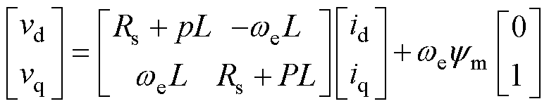
表贴式永磁同步电机在转子dq坐标系下的基波电压方程为
(1)
式中,vd和vq分别为d、q轴电压;id和iq分别为d、q轴电流;Rs和L分别为定子电阻、定子电感; 为转子电角速度;
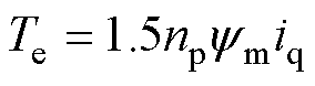
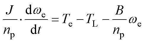
 为永磁体磁链;p为微分算子。电磁转矩方程和运动方程分别为
 (2)
(2)
 (3)
(3)
 (4)
(4)
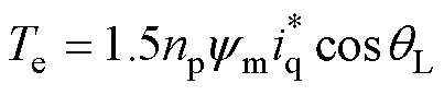
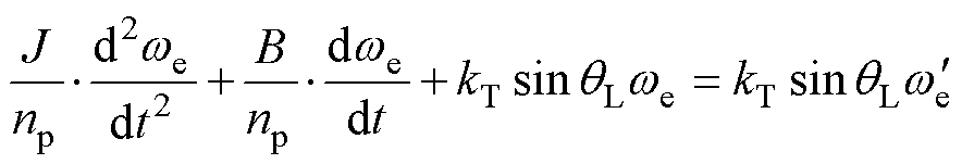
式中,Te为电磁转矩;np为电机极对数;J为转动惯量;TL为负载转矩;B为阻尼系数;qe为电角度。
传统I-f控制的框图如图1所示,由于真实转子角度未知,I-f控制所采用的角度信号由开环电角速度 积分得到,有
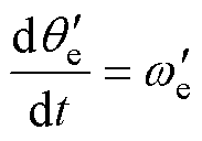 (5)
(5)
式中,上标' 代表开环 坐标系中的对应物理量。
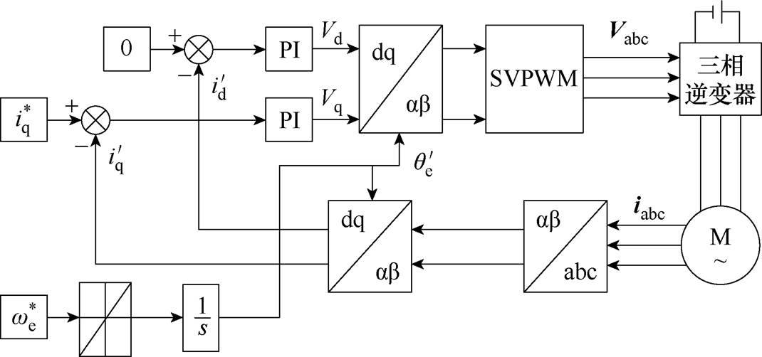
图1 传统的I-f起动方法
Fig.1 Conventional I-f startup method
假设开环坐标系与真实转子dq坐标系之间的相位 为
为
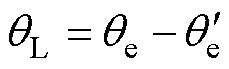 (6)
(6)
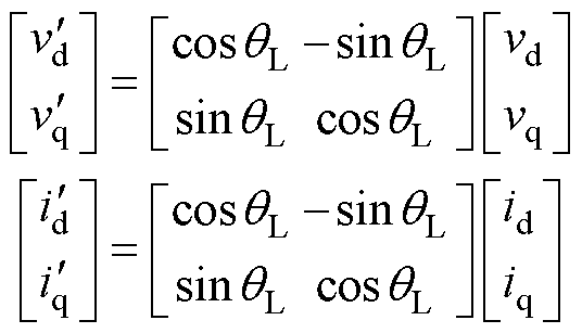
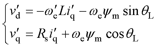
真实转子dq坐标系与开环坐标系如图2所示。则使用Park反变换将式(1)变换到开环坐标系得
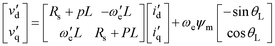 (7)
(7)
其中
式中, 和
和 分别为
分别为 、
、 轴电压;
轴电压; 和
和 分别为、轴电流;为、轴转子电角速度;为真实dq轴和开环dq次轴的相位差。
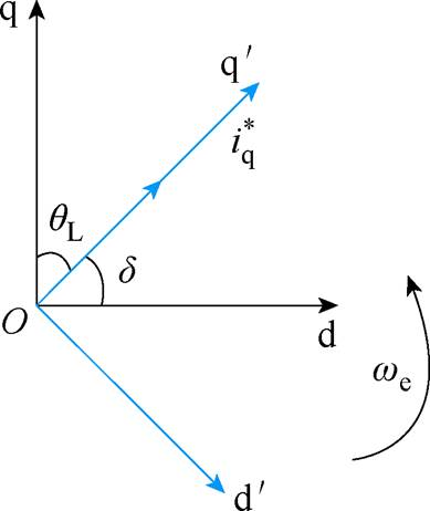
图2 真实转子dq坐标系与开环 坐标系
坐标系
Fig.2 The rotor coordinate and the open coordinate
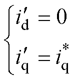
假设在开环坐标系中采用d轴电流给定值 =0控制且不考虑电流环控制的动态过程,则
 (8)
(8)
则真实转子dq坐标系中的dq轴电流为
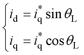 (9)
(9)
式中, 为q轴电流给定值。代入式(2)可得I-f控制所产生的电磁转矩为
 (10)
(10)
将式(10)代入运动方程式(3),并对其两边同时求导得
 (11)
(11)
式中, 为系数,
为系数,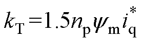 。可以看出,系统稳定条件是
 ,且稳态时=。但当系统自身阻尼系数B较小时,将产生明显振荡,甚至在负载扰动下,产生不稳定。
在B一定时,较小的起动电流虽然可一定程度上减小自振频率进而减轻振荡,但会降低电机起动的成功率,而较大的则可能会在I-f控制向转速闭环控制切换时产生转速过冲问题。
根据式(11),在I-f控制中,控制器只能调节起动电流与开环角速度。为了保证电机起动的成功率,必须采用较大的,但越大,kT越大,在相同负载转矩时, 也越大,系统阻尼反而越小,所以必须通过调节增大系统阻尼。忽略电流动态时,式(7)变为
 (12)
(12)
注意到式(12)两个方程的右侧第二项中含有电机真实,又考虑到在电机轻载时更容易产生振荡,此时的相对 更大,基于此,本文提出一种基于轴电压微分的振荡抑制策略,所设计的控制率为
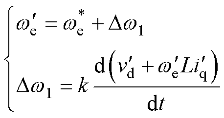 (13)
(13)
式中, 为给定的开环电角速度;k为可调增益;Dw1为基于d轴电压微分的补偿项。
将式(12)代入式(13)整理可得
 (14)
(14)
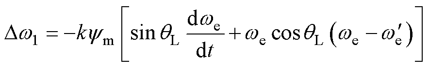
代入式(11)可知,等号右侧的第一项为系统提供了额外的阻尼,整理后得
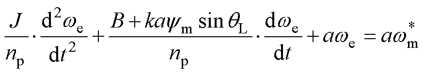 (15)
(15)
其中
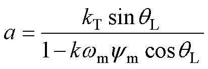
式中, 为转子机械角速度。
系统稳定的充要条件为a>0,因此可调增益k的稳定极限为
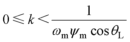 (16)
(16)
所提出的转速振荡抑制策略的控制框图如图3所示,因为纯微分会放大高频段信号,所以在实际实现时串联了低通滤波器。与文献[12-13]中基于有功功率扰动的频率补偿环相比,本文提出的方法更加直观,且对转速振荡的抑制效果更加显著,这一点将在第3节的实验验证部分进行展示。
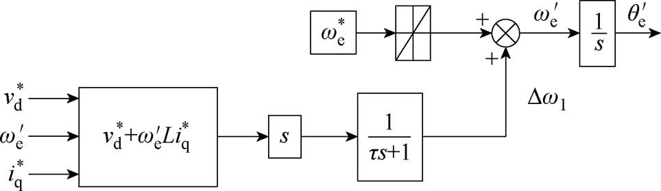
图3 所提出的基于 轴电压微分的振荡抑制策略
Fig.3 The proposed speed oscillation suppression based on derivative of-axis voltage
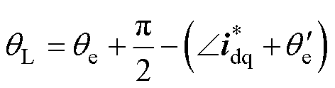
为了实现从I-f控制到转速闭环控制的平滑切换且提高切换过程的抗扰动能力,本文提出一种基于电流动态与角度动态解耦的平滑切换策略,如图4所示。该策略在切换过程中保持电流矢量 相对真实转子q轴的夹角
 不变,从而不会引起机械动态,即
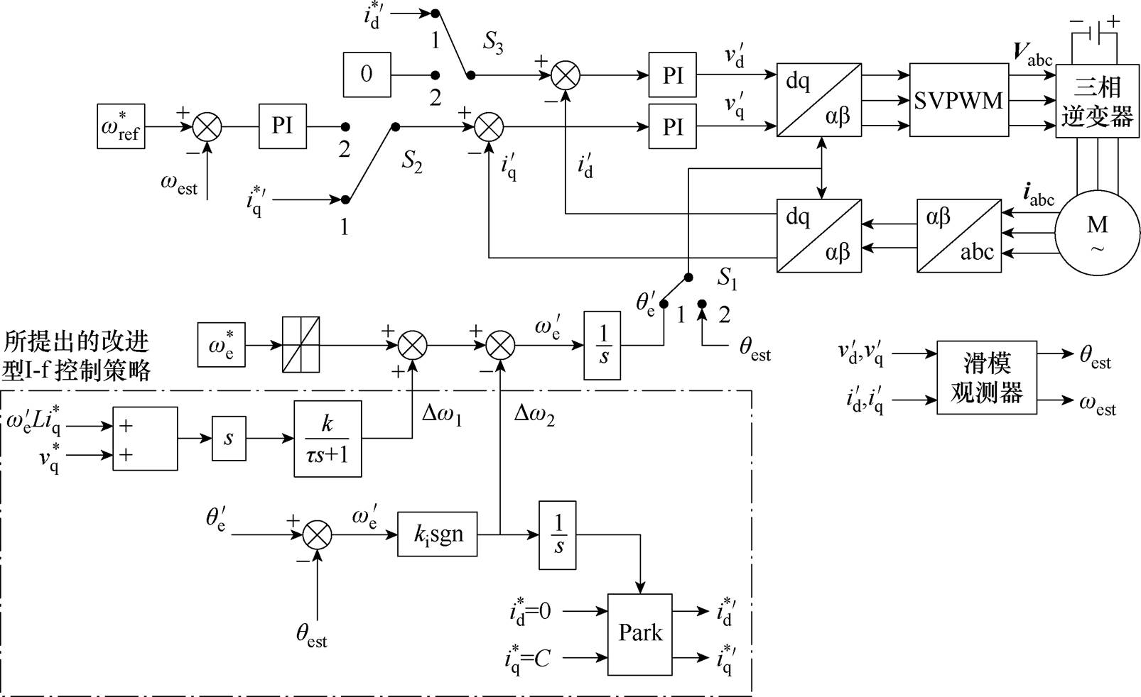
图4 所提出的基于改进I-f控制的永磁同步电机无位置控制策略
Fig.4 The proposed sensorless control of permanent magnet synchronous motors based on improved I-f control
 (17)
(17)
为此,在每个控制周期通过Park变换改变的相位,有
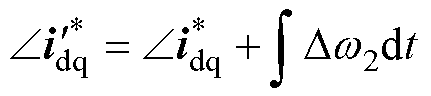 (18)
(18)
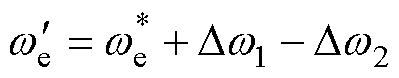
式中,Dw2为补偿项。并同步调整开环坐标系角度 为
为
 ,即只需要在式(13)基础上增加
 项,式(13)变为
 (19)
(19)
其中
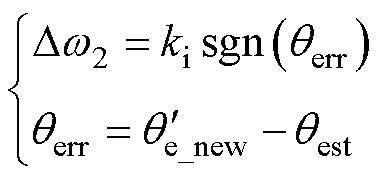 (20)
(20)
式中,ki为积分增益;sgn( · )为符号函数; 为滑模观测器估计出的真实转子角度;
 为式(19)中积分得到。电流矢量角度和坐标系角度变化过程如图5所示。当的相位达到
 时,如图5b所示,补偿后的开环角度达到真实转子角度,有
 (21)
(21)
式中, 为下个周期的相位。
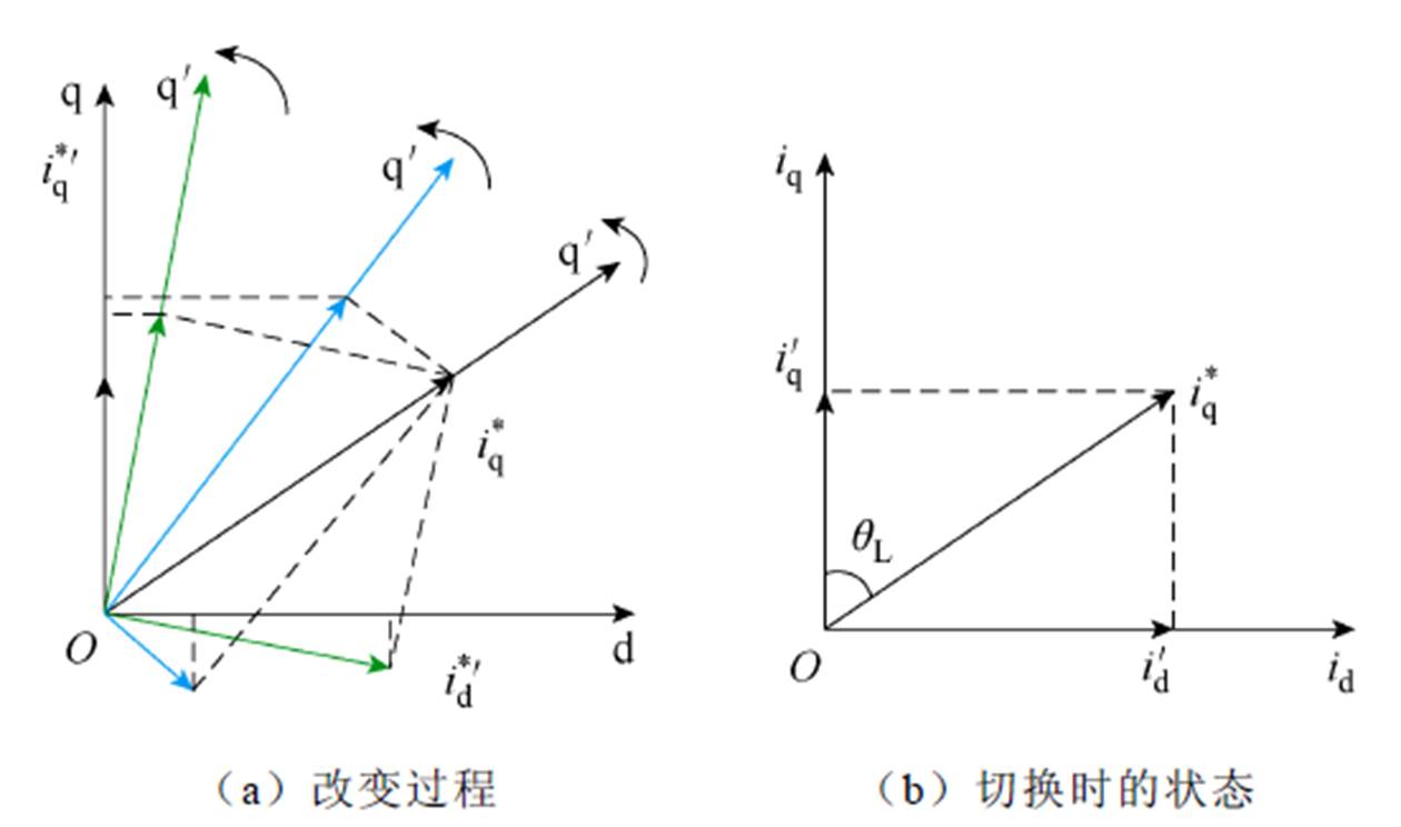
图5 电流矢量角度和坐标系角度变化过程
Fig.5 Change of current vector and open coordinate
此时即可实现无误差的角度切换和无转矩波动的 切换,进入转速闭环控制,之后再逐步将降为0,完成整个切换过程。因为角度切换时没有任何的角度误差,所以不会引起电流动态,实现了切换过程电流动态与角度动态的解耦。同时,在切换过程中,电流幅值保持恒定,因此相对于文献[17, 22-23]中减少iq幅值的切换方法,本策略在实现平滑切换的同时提高了切换过程的抗负载扰动能力,保障电机在切换过程中不会发生失步。
所提出的改进型I-f控制策略完整实现步骤为:
(1)采用=0控制,给定和开环转速斜坡,拖动电机开始旋转,同时使用第2.1节所提出的基于开环d轴电压微分的策略抑制转速振荡。
(2)当达到滑模观测器的工作转速后,根据角度误差,使用Park变换旋转电流矢量并同步补偿开环坐标系角度。当等于位置观测器得到的真实角度时,切换角度和,进入正常转速闭环控制。
(3)在进入转速闭环控制后,根据一定轨迹将减小到0,完成整个电机起动过程。
为了对所提出的改进型I-f控制策略进行验证,搭建了永磁同步电机实验平台,并从转速振荡抑制和切换策略两个方面与文献[13, 22]中的方法进行了实验对比。实验采用两台型号为PML601永磁同步电机组成的对拖平台,电机具体参数见表1,电机带有光电式编码器,用于获得转子位置和速度,并仅用于验证,采用STM32F405RGT6为电机驱动器的控制芯片,控制频率为10 kHz。实验平台如图6所示。
表1 电机参数
Tab.1 Machine parameters
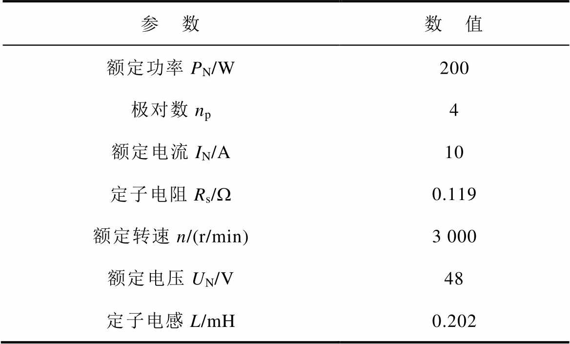
参 数数 值 额定功率PN/W200 极对数np4 额定电流IN/A10 定子电阻Rs/W0.119 额定转速n/(r/min)3 000 额定电压UN/V48 定子电感L/mH0.202
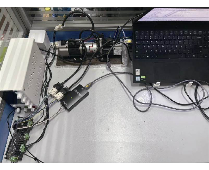
图6 实验平台
Fig.6 Experimental setup
为了验证所提出的基于开环d轴电压微分的转速振荡抑制策略的有效性,分别对传统I-f控制策略、文献[13]中基于有功功率扰动的转速振荡抑制策略、所提出的转速振荡抑制策略三种情况进行实验测试。给定转速为500 r/min,电频率斜坡为120 Hz/s,电机在同一角度下起动,实验结果如图7所示。
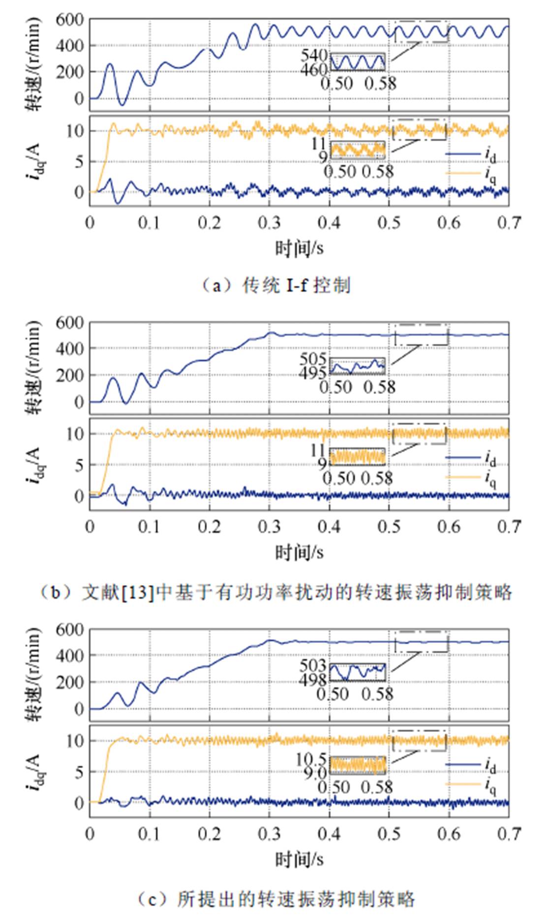
图7 转速振荡抑制策略实验结果对比
Fig.7 Results of speed ripple suppresion strategies
由图7可以看出,传统开环I-f控制在电机起动阶段产生了明显了转速振荡,稳态转速波动峰峰值约80 r/min,这是电机系统阻尼低的表现。文献[13]中的方法可使转速在0.1 s后快速衰减,稳态转速波动峰峰值降至约10 r/min。而本文所提出的方法在0~0.1 s时对转速波动的衰减更快,且稳态转速波动峰峰值进一步降至约5 r/min。
为了进一步验证所提出的转速振荡抑制策略在大惯量负载情况下的有效性,在负载电机转矩给定加入转动惯量增量与角速度微分乘积项 的方法将电机的转动惯量模拟增大到原来的2.2倍,并对三种情况进行实验测试,如图8所示。
如图8a可以看出,在电机加大转动惯量后,电机转速波动明显下降,稳态转速波动峰峰值约18 r/min。而本文所提的方法在0~0.1 s时对转速波动起到了很好的抑制效果,稳态转速波动峰峰值也下降了10 r/min左右,如图8c所示。
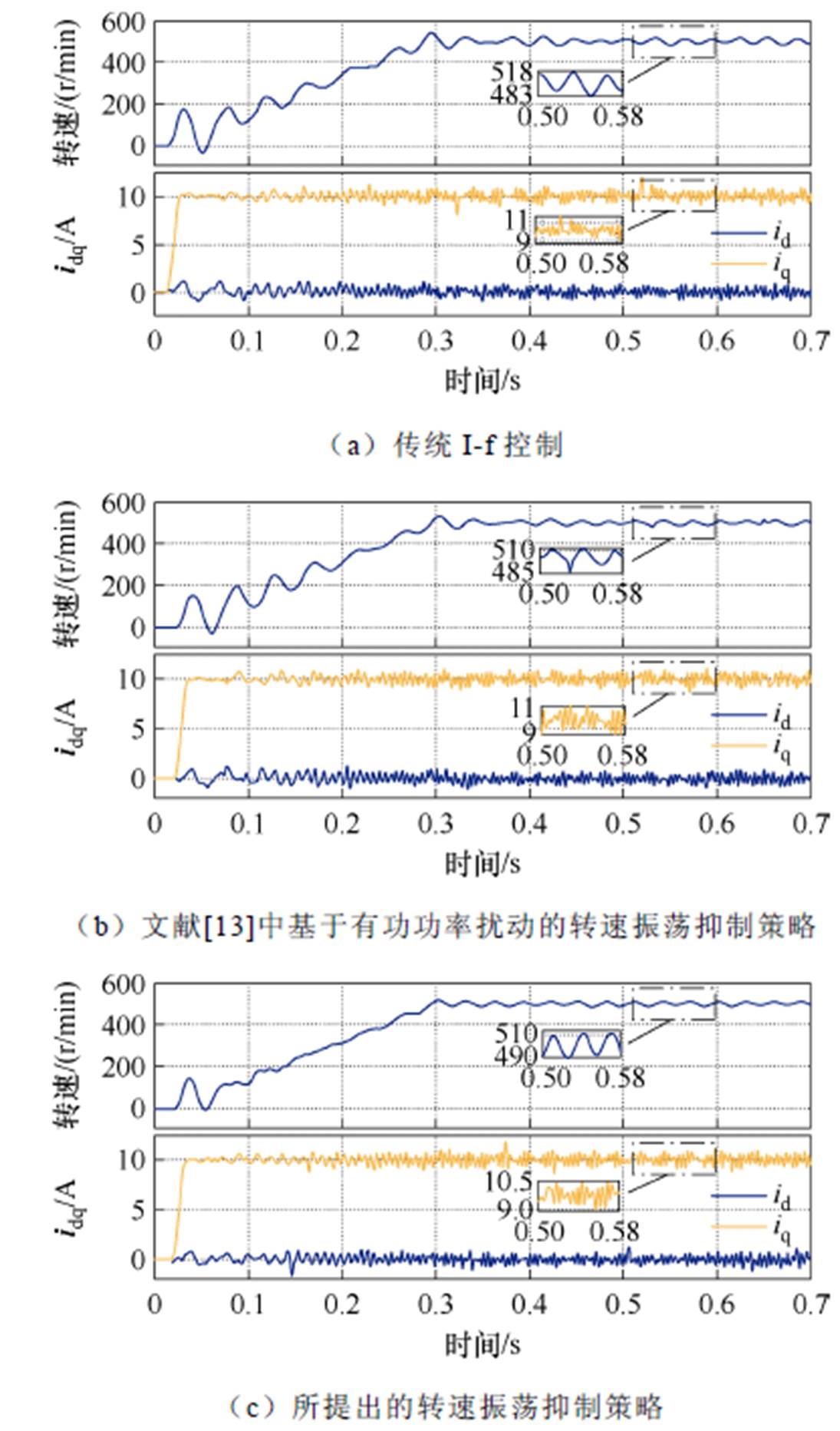
图8 增大惯量,转速振荡抑制策略实验结果对比
Fig.8 Results of speed ripple suppresion strategies under larger rotational inertia
给定电机转速为500 r/min,分别在电机空载、0.064 N·m负载突变、0.16 N·m负载突变情况下,将本文提出的切换策略与文献[22]中所采用的切换策略进行对比实验。
其中,负载突变发生在切换进行前70 ms。空载时切换策略实验结果对比如图9所示。从图9a可以看出,文献[22]中的方法在减小时产生了机械动态,转速在0.2~0.3 s有一定程度下降,而本文所提出的方法则不会产生机械动态,转速在0.2~0.3 s波动较小,如图9b所示。
在切换过程中,施加一个0.064 N·m的负载扰动时,文献[22]中方法的转速下降了260 r/min左右,而本文所提出方法的转速只下降了40 r/min,转速波动更小,抗干扰性能更强,如图10a和图10b所示。
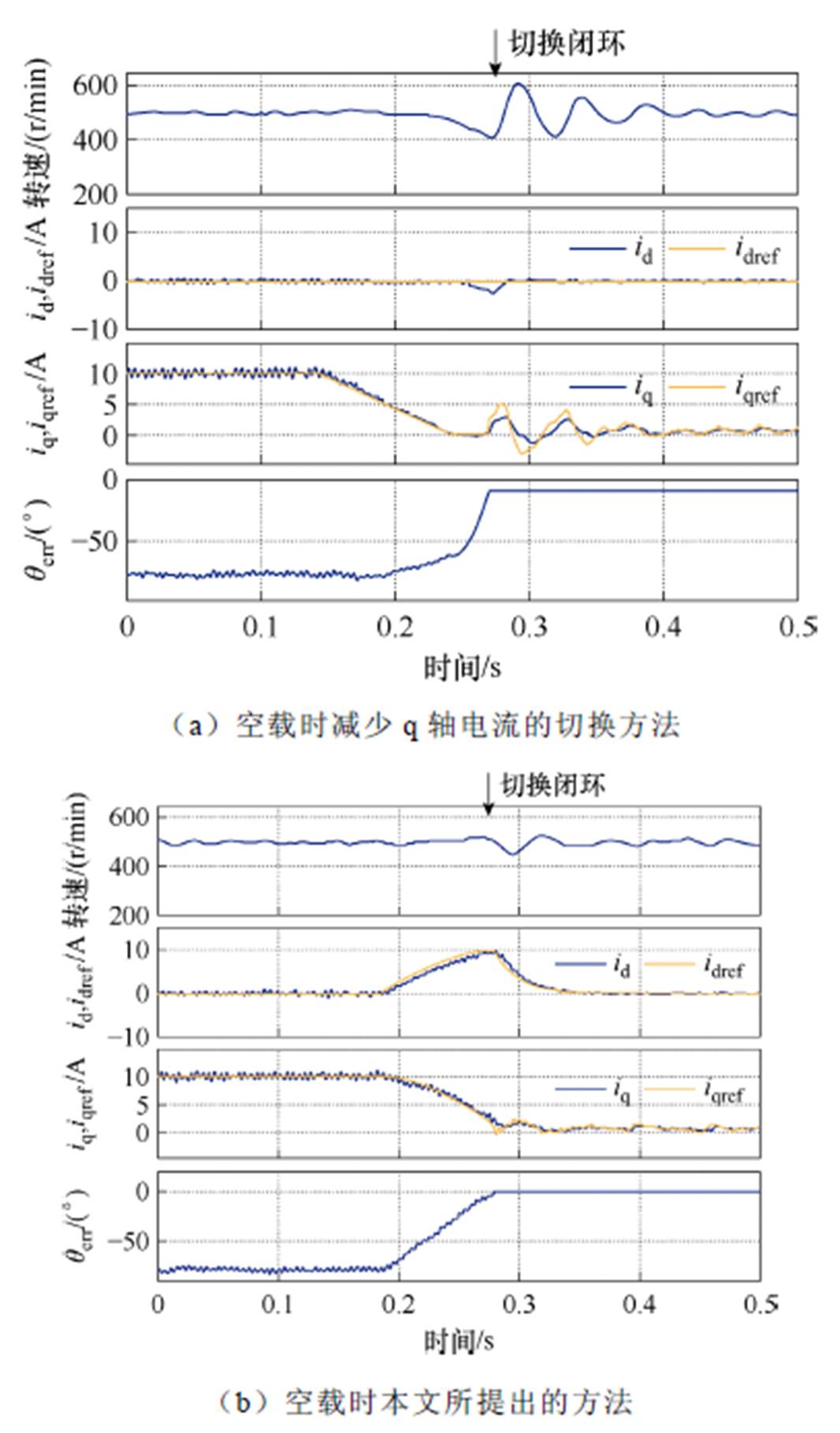
图9 空载时切换策略实验结果对比
Fig.9 Comparison of experimental results on transitionstrategies under no-load
如果将负载扰动增加到0.16 N·m,文献[22]中的方法在切换过程中遇到负载扰动时产生电机失步,而本文所提出的方法转速下降了40 r/min,依然可以保持正常运行,如图11a和图11b所示。如图12所示,将负载扰动增加到0.512 N·m,本文所提出的方法仍能成功过渡到闭环阶段。
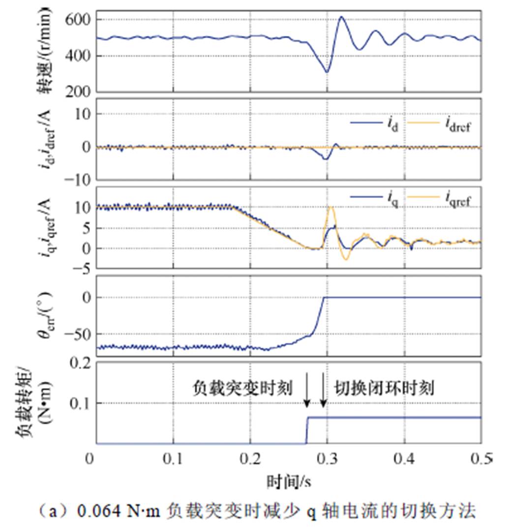
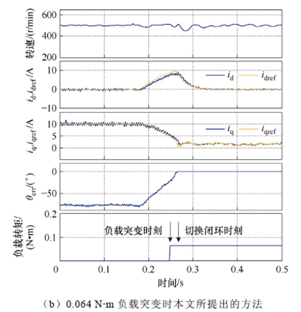
图10 0.064 N·m负载突变情况下切换策略实验结果对比
Fig.10 Comparison of transition strategies under 0.064 N·m load disturbance
本文提出了一种改进型I-f控制策略,使用开环d轴电压微分补偿开环频率给定,抑制了转速振荡,并基于电流动态与角度动态解耦的切换策略,提高了I-f控制向转速闭环控制切换的平滑性和抗负载扰动能力,并得到了实验验证,具有一定的工程应用前景。
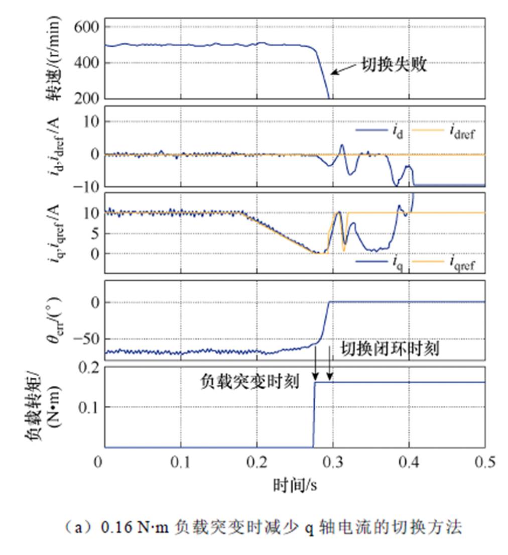
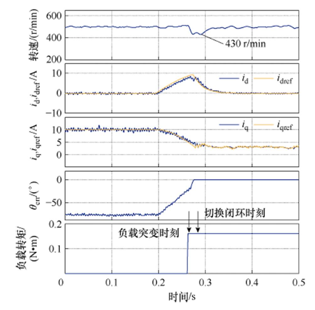
图11 0.16 N·m负载突变情况下切换策略实验结果对比
Fig.11 Comparison of transition strategies under 0.16 N·m load disturbance
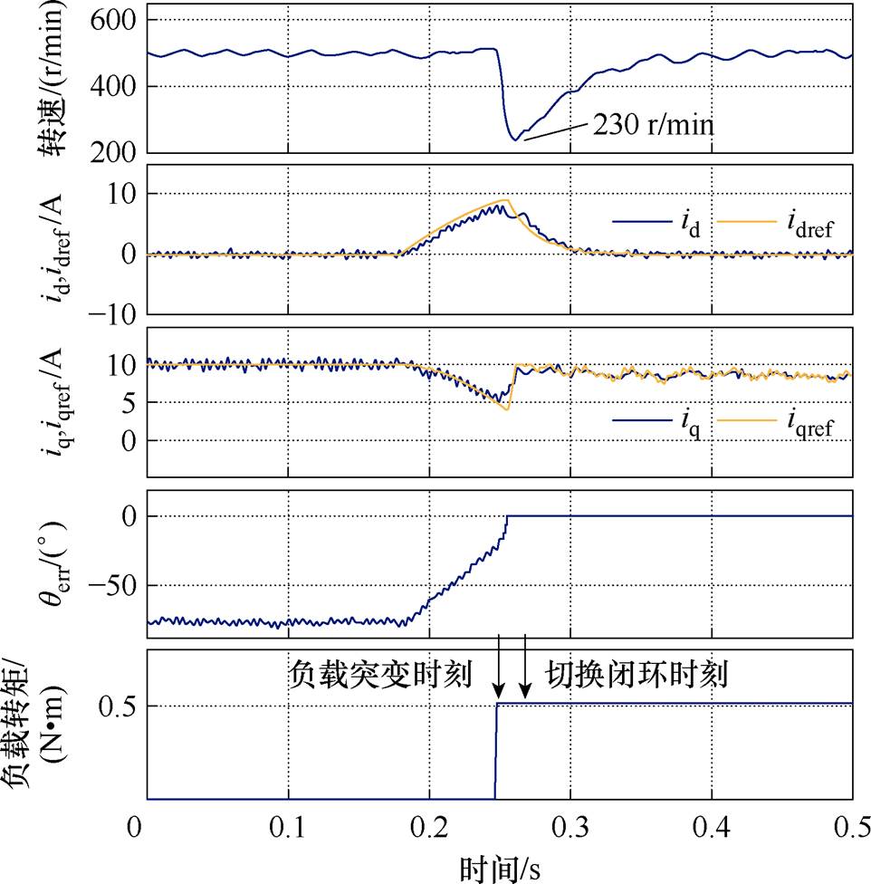
图12 0.512 N·m负载突变时本文所提出的方法
Fig.12 Comparison of transition strategies under 0.512 N·m load disturbance
参考文献
[1] 肖鑫, 孙乐, 甘辉. 基于抗扰扩展卡尔曼滤波的摇臂伺服控制[J]. 中国电机工程学报, 2023, 43(20): 8102-8114.
Xiao Xin, Sun Le, Gan Hui. Swing servo control based on extended Kalman filter with disturbance- rejection[J]. Proceedings of the CSEE, 2023, 43(20): 8102-8114.
[2] 兰志勇, 李延昊, 罗杰, 等. 一种自适应扩展卡尔曼滤波的永磁同步电机无位置传感器矢量控制[J]. 电机与控制学报, 2024, 28(3): 141-148.
Lan Zhiyong, Li Yanhao, Luo Jie, et al. Sensorless vector control of permanent magnet synchronous motor based on adaptive extended Kalman filter[J]. Electric Machines and Control, 2024, 28(3): 141-148.
[3] 朱国宇, 安兴科, 诸德宏, 等. 基于改进自适应超螺旋观测器的永磁同步电机无位置控制[J]. 电气工程学报, 2023, 18(4): 84-95.
Zhu Guoyu, An Xingke, Zhu Dehong, et al. Position sensorless control for permanent magnet synchronous motor using improved adaptive super twisting observer[J]. Journal of Electrical Engineering, 2023, 18(4): 84-95.
[4] 吕德刚, 刘站卓, 徐翔. 带负载扰动补偿的永磁同步电机改进MRAS观测器控制[J]. 电机与控制学报, 2023, 27(6): 46-54.
Lü Degang,Liu Zhanzhuo, Xu Xiang. Improved MRAS observer control of permanent magnet syn- chronous motors with load disturbance com- pensation[J]. Electric Machines and Control, 2023, 27(6): 46-54.
[5] 孙庆国, 朱晓磊, 牛峰, 等. 基于改进型积分滑模观测器的PMSM无位置传感器控制[J]. 中国电机工程学报, 2024, 44(8): 3269-3278.
Sun Qingguo, Zhu Xiaolei, Niu Feng, et al. Sensorless control of permanent magnet synchronous motor based on improved integral sliding mode observer[J]. Proceedings of the CSEE, 2024, 44(8): 3269-3278.
[6] 赵文祥, 宋世昌, 周书文, 等. 改进滑模观测器的电流源逆变器驱动PMSM无位置传感器控制[J]. 电工技术学报, 2024, 39(4): 987-995.
Zhao Wengxiang, Song Shichang, Zhou Shuwen, et al. Sensorless control of current source inverter driven PMSM with improved sliding mode observer[J]. Transactions of China Electrotechnical Society, 2024, 39(4): 987-995.
[7] Wang Gaolin, Valla M, Solsona J. Position sensorless permanent magnet synchronous machine drives-a review[J]. IEEE Transactions on Industrial Electro- nics, 2020, 67(7): 5830-5842.
[8] 徐奇伟, 熊德鑫, 陈杨明, 等. 基于新型高频纹波电流补偿方法的内置式永磁同步电机无传感器控制[J]. 电工技术学报, 2023, 38(3): 680-691.
Xu Qiwei, Xiong Dexin, Chen Yangming, et al. Research on sensorless control strategy of IPMSM based on new high frequency ripple current com- pensation method[J]. Transactions of China Elec- trotechnical Society, 2023, 38(3): 680-691.
[9] 张彦平, 尹忠刚, 苏明, 等. 基于共振扩张状态观测器的内置式永磁同步电机统一全速域无位置传感器控制[J]. 电工技术学报, 2023, 38(22): 6070- 6081.
Zhang Yanping, Yin Zhonggang, Su Ming, et al. Unified full speed sensorless control of interior permanent magnet synchronous motor based on resonance extended state observer[J]. Transactions of China Electrotechnical Society, 2023, 38(22): 6070- 6081.
[10] 朱小芬, 黄科元, 黄守道. 一种稳定的高速永磁同步电机V/F控制方法[J]. 电力电子技术, 2018, 52(7): 28-32.
Zhu Xiaofen, Huang Keyuan, Huang Shoudao. A stable V/F control method of high-speed permanent magnet synchronous motor[J]. Power Electronics, 2018, 52(7): 28-32.
[11] Nair S V, Hatua K, Prasad N V P R D, et al. A quick I-f starting of PMSM drive with pole slipping prevention and reduced speed oscillations[J]. IEEE Transactions on Industrial Electronics, 2021, 68(8): 6650-6661.
[12] Chen Dunzhi, Lu Kaiyuan, Wang Dong, et al. I-F control with zero D-axis current operation for surface-mounted permanent magnet synchronous machine drives[J]. IEEE Transactions on Power Electronics, 2023, 38(6): 7504-7513.
[13] Chen Dunzhi, Lu Kaiyuan, Wang Dong. An I-f startup method with compensation loops for PMSM with smooth transition[J]. IEEJ Journal of Industry Applications, 2020, 9(3): 263-270.
[14] 刘计龙, 肖飞, 麦志勤, 等. IF控制结合滑模观测器的永磁同步电机无位置传感器复合控制策略[J]. 电工技术学报, 2018, 33(4): 919-929.
Liu Jilong, Xiao Fei, Mai Zhiqin, et al. Hybrid position-sensorless control scheme for PMSM based on combination of IF control and sliding mode observer[J]. Transactions of China Electrotechnical Society, 2018, 33(4): 919-929.
[15] 刘计龙, 肖飞, 麦志勤, 等. 基于双dq空间的永磁同步电机无位置传感器起动策略[J]. 电工技术学报, 2018, 33(12): 2676-2684.
Liu Jilong, Xiao Fei, Mai Zhiqin, et al. Position- sensorless startup strategy for permanent magnet synchronous motor based on double dq space[J]. Transactions of China Electrotechnical Society, 2018, 33(12): 2676-2684.
[16] 付康壮, 刘计龙, 麦志勤, 等. 改进型IF控制结合有效磁链法的永磁同步电机全速域无位置传感器控制策略[J]. 电工技术学报, 2022, 37(22): 5704- 5716.
Fu Kangzhuang, Liu Jilong, Mai Zhiqin, et al. A full-speed domain sensorless control strategy for permanent magnet synchronous motor based on improved IF control and effective flux method[J]. Transactions of China Electrotechnical Society, 2022, 37(22): 5704-5716.
[17] Tang Qipeng, Chen Duxin, He Xiangning. Integration of improved flux linkage observer and I-f starting method for wide-speed-range sensorless SPMSM drives[J]. IEEE Transactions on Power Electronics, 2020, 35(8): 8374-8383.
[18] Xu Yao, Lin Cheng, Xing Jilei, et al. I-f starting rapid and smooth transition method of full-speed sensorless control for low current harmonic ultra-high-speed PMSM[C]//2022 IEEE Applied Power Electronics Conference and Exposition (APEC), Houston, TX, USA, 2022: 1820-1826.
[19] Nair S V, Hatua K, Durga Prasad N V P R, et al. Quick and seamless transition method for I-f to sensorless vector control changeover and on-the-fly start of PMSM drives[J]. IET Electric Power Applications, 2020, 14(11): 2231-2242.
[20] Li Qidong, Wang Xudong, Jiang Jia, et al. Sensorless control for surface mounted PM machine with a high inertial load[J]. CES Transactions on Electrical Machines and Systems, 2018, 2(1): 116-122.
[21] Fatu M, Teodorescu R, Boldea I, et al. I-F starting method with smooth transition to EMF based motion-sensorless vector control of PM synchronous motor/generator[C]//2008 IEEE Power Electronics Specialists Conference, Rhodes, Greece, 2008: 1481- 1487.
[22] Wang Zihui, Lu Kaiyuan, Blaabjerg F. A simple startup strategy based on current regulation for back-EMF-based sensorless control of PMSM[J]. IEEE Transactions on Power Electronics, 2012, 27(8): 3817-3825.
[23] Xing Jilei, Qin Zhidong, Lin Cheng, et al. Research on startup process for sensorless control of PMSMs based on I-f method combined with an adaptive compensator[J]. IEEE Access, 2020, 8: 70812-70821.
Sensorless Control of Permanent Magnet Synchronous Motor Based on Improved I-f Control
Abstract Traditional I-f control for sensorless control of the permanent magnet synchronous motor (PMSM) suffers from poor damping and disturbance rejection, which lead to large speed oscillations at motor startup and long transition time when switching to close-loop control. It is unfavorable for multi-rotor unmanned aerial vehicles and electric vertical take-off vehicles. According to the differentiation of d-axis voltage and transition strategy, this paper proposes an improved I-f control strategy with frequency compensation to increase damping and improve disturbance rejection of the I-f control based on decoupling current dynamics and angle dynamics. Speed oscillations at motor startup are suppressed significantly, and a fast transition from I-f control to closed-loop control is achieved smoothly with less mechanical dynamics.
Firstly, a small-signal perturbation model of the I-f control is deduced with detailed analyses of its damping characteristics. To increase damping and suppress speed oscillations, differentiation of the open-loop d-axis voltage is used to compensate for the open-loop frequency. Secondly, to improve the load disturbance rejection when switching to closed-loop control, the angle of the reference current vector is rotated via Park transformation. In contrast, the open loop angle is increased to gradually approach the real rotor angle obtained by the angle observer. Since the reference current vector is stationary relative to the real rotor angle during this transition process, no mechanical dynamics are generated. This transition can even be done at zero angle error between the real rotor coordinate and the open-loop coordinate, which indicates no current and angle dynamics at the switching instant. The amplitude of the reference current vector is kept unchanged throughout the whole I-f control. Therefore, the load disturbance is effectively rejected, even during the transition process. Finally, after switching to closed-loop control successfully, the d-axis current is decreased to 0 according to a certain trajectory, and normal closed-loop control takes over.
Two experiments demonstrate the improvement of system damping and load disturbance rejection. In the first experiment, the proposed strategy is compared with the traditional I-f control and the perturbation of active power in literature. The experimental results show that under traditional I-f control, significant speed oscillations occur during the starting phase, and the peak-to-peak value of speed oscillations is about 80 r/min. With perturbation of active power, speed oscillations rapidly decay in 0.1 seconds, and the peak-to-peak value of speed drops to about 10 r/min in the steady state. The motor attenuates speed oscillations fast, and the peak-to-peak value of speed drops to about 5 r/min in the steady state.
The second experiment compares the proposed transition strategy and the strategy by reducing the q-axis current in the literature. The experimental results show that reducing the q-axis current generates large mechanical dynamics at the transition stage under sudden load disturbances. The speed decreases by about 260 r/min at the load disturbance of 0.064 N·m, and the motor is out of control at the load disturbance of 0.16 N·m. Mechanical dynamics are much smaller using the proposed method. The speed decreases by about 40 r/min at the load disturbance of 0.064 N·m, and the motor can still maintain normal operation at the load disturbance of 0.512 N·m.
The proposed improved I-f control strategy has better damping effect on speed oscillations and can transition to closed-loop control with strong rejection of load disturbances.
keywords:Permanent magnet synchronous machine (PMSM), sensorless control, I-f control, damping, transition strategy
中图分类号:TM341; TM351
DOI: 10.19595/j.cnki.1000-6753.tces.240858
湘潭大学博士科研启动项目(22QDZ25)和广东省基础与应用基础研究基金项目(2022A1515110063)资助。
收稿日期 2024-05-23
改稿日期2024-07-31
李 福 男,1991年生,博士,讲师,硕士生导师,研究方向为电机控制。
E-mail: eelifu@xtu.edu.cn
陈双琛 男,1998年生,硕士研究生,研究方向为电机无感控制。
E-mail: csc9821@163.com(通信作者)
(编辑 崔文静)