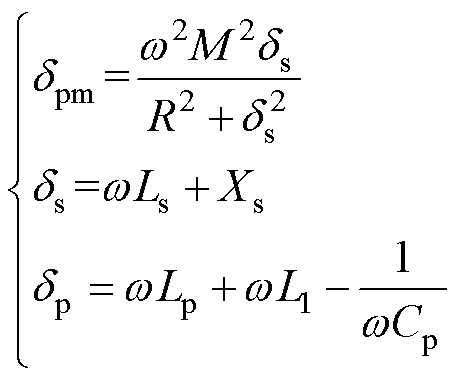
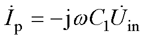
 为输入电压,电感L1与电容C1、Cp构成原边补偿网络,电感L2与电容C2、Cs构成副边为LCC和CLC型的补偿网络,电容Cs构成副边为S型的补偿网络,
 为系统输入电流,
 和
和 分别为发射线圈(Transmitter Coil, TX)电流与接收线圈(Receiver Coil, RX)电流。Lp、Ls分别为发射线圈与接收线圈自感,Rp、Rs分别为发射线圈与接收线圈内阻,M为耦合器互感,Req为最大系统效率所对应的最优交流负载电阻[22]。
摘要 频率调谐方法可以有效解决因耦合机构参数漂移导致的无线电能传输系统频率失谐问题,有利于提高系统的传输效率及运行稳定性。传统的双边频率调谐控制方法不统一,并且控制参数优化复杂。为此,该文提出一种适用于高阶补偿无线电能传输系统的通用调谐解耦控制策略。首先,基于电路理论构建高阶补偿无线电能传输系统的分析模型,揭示双边谐振条件及其特征。其次,基于扰动观察法构建一种通用的双边调谐解耦控制策略,可实现原边和副边谐振参数的自适应调整。最后,搭建180 W LCC/LCC系统实验样机,验证了所提频率调谐解耦控制策略的有效性,在耦合机构偏移等工况下能够有效维持系统双边的谐振状态,提高了系统的传输效率和稳定性。
关键词:解耦控制 频率调谐 参数漂移 无线电能传输
无线电能传输(Wireless Power Transfer, WPT)作为一种非接触的供电方式,仅通过磁场耦合就可以将电能从供电端传递到负载,具有可靠、安全、高自由度等优点,近年来在电动车[1-4]、水下设备[5]和移动电话[6-7]等应用场合得到广泛关注。然而,实际应用中难免会发生耦合机构参数偏移现象,导致线圈自感波动,使得WPT系统出现频率失谐问题,从而影响其传输特性及运行稳定性[8-9]。因此,开展WPT系统的频率调谐研究具有重大意义。
为解决WPT系统的频率失谐问题,学者们已经从单边频率调谐和双边频率调谐等角度提出了多种有效方法。对于单边频率调谐,文献[10]通过减小串联-串联(Series-Series, SS)补偿WPT系统中逆变器输出电压和电流的相位差,使开关频率跟随谐振频率,以实现WPT系统原边频率调谐。随后,该方法被应用在串联-并联(Series-Parallel, SP)、并联-并联(Parallel-Parallel, PP)和LCL/P补偿WPT系统的原边频率调谐[11]。由于系统工作频率的带宽限制,仅能在较窄的频率范围内进行调谐,且副边无法实现主动调谐[12-13]。近年来,可调电容(Switch-Controlled Capacitor, SCC)逐渐被用来解决WPT系统的频率失谐问题,通过动态调整补偿电容值来维持系统的谐振状态。譬如,在文献[14]中,通过检测逆变器输出电压和电流的相位差,借此来调整LCC/S WPT系统的原边谐振电容,从而提升系统的传输效率。如果副边线圈自感波动,也可以调整副边补偿电容,以保持LCC/S WPT系统的副边谐振状态[15]。
为实现WPT系统双边频率调谐,文献[16]提出了一种基于参数辨识的LCC/S WPT系统双边调谐控制策略,通过所辨识的原、副边自感参数来调节双边的可调电容。此外,文献[17]基于可调电容电路提出了一种不需要参数辨识的SS WPT系统的双边频率调谐方法。以上两种方法都需要使用无线通信模块实现WPT系统的双边数据交互。为避免无线数据传输的延时问题,文献[18]针对高阶补偿LCC/S WPT系统,提出了一种基于原边零相角控制和副边最大电流搜索的双边频率调谐解耦控制方法,该方法原边频率调谐控制较为复杂,且PI参数整定困难。
为提升高阶补偿WPT系统双边频率调谐控制方法的普适性和自适应性,本文提出了一种通用型调谐解耦控制策略。首先,基于电路理论构建了高阶补偿WPT系统的分析模型,着重分析了高阶补偿WPT系统双边谐振状态的电气特征。在此基础上,提出了一种适用于高阶补偿WPT系统的通用调谐解耦控制策略,实现了双边调谐参数的自适应寻优。最后,以LCC/LCC WPT系统为例,搭建了180 W实验样机,验证了所提频率调谐控制策略的有效性,对参数波动具有很好的鲁棒性,有助于提高WPT系统的传输效率和稳定性。
针对传统S/S、S/P、P/P和P/S等低阶补偿WPT系统的双边频率调谐问题,由于其双边谐振状态会相互影响[19],无法实现频率调谐的解耦控制,往往需借助蓝牙[17]或无线射频(Radio Frequency, RF)模块[20]等措施来实现低阶补偿WPT系统的双边调谐控制。为此,本文重点研究高阶补偿WPT系统。
目前主流的高阶补偿网络是T型、p 型及两者的衍生拓扑组成[21],为简化分析过程,本文以LCC/LCC、LCC/S、CLC/CLC和CLC/S这四种T型高阶补偿网络为例进行分析,如图1所示。其中,为输入电压,电感L1与电容C1、Cp构成原边补偿网络,电感L2与电容C2、Cs构成副边为LCC和CLC型的补偿网络,电容Cs构成副边为S型的补偿网络,为系统输入电流,和分别为发射线圈(Transmitter Coil, TX)电流与接收线圈(Receiver Coil, RX)电流。Lp、Ls分别为发射线圈与接收线圈自感,Rp、Rs分别为发射线圈与接收线圈内阻,M为耦合器互感,Req为最大系统效率所对应的最优交流负载电阻[22]。
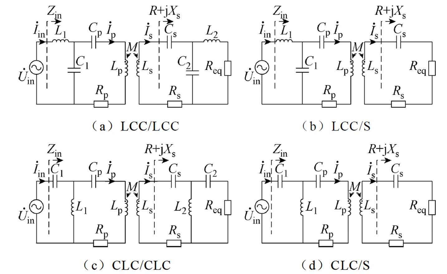
图1 高阶补偿WPT系统
Fig.1 The high-order compensation WPT system
在进行理论分析之前,需要做一些假设:
(1)高阶补偿LCC/S和CLC/S的WPT系统始终满足wL1=1/(wC1);高阶补偿LCC/LCC和CLC/CLC的WPT系统始终满足wL1=1/(wC1)和wL2=1/(wC2)。
(2)调谐过程中,输入电压有效值Uin和互感值M保持恒定。
原边LCC补偿的WPT系统,譬如LCC/LCC和LCC/S补偿网络,如图1a和图1b所示。为简化分析过程,其等效电路如图2所示。
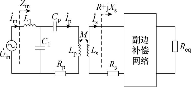
图2 原边LCC补偿的WPT系统
Fig.2 Primary-side LCC compensated WPT systems
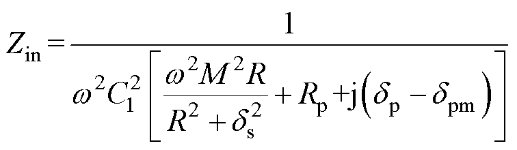
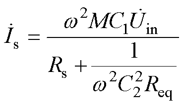
根据基尔霍夫定律,推导可得系统的输入阻抗Zin为
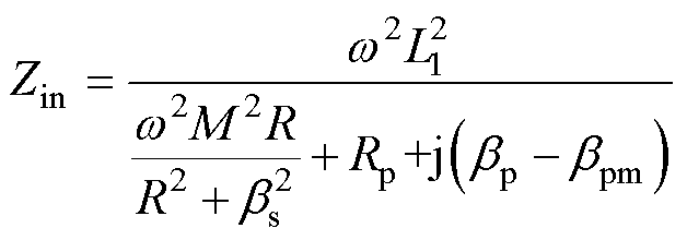 (1)
(1)
其中
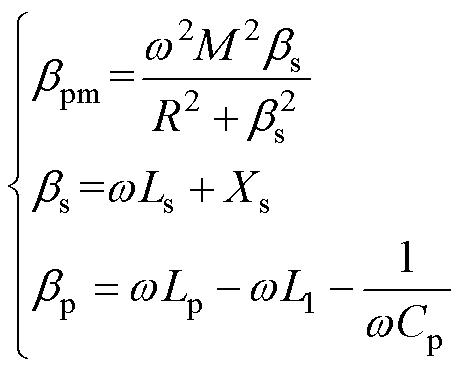 (2)
(2)
式中, 为LCC/LCC和LCC/S补偿网络副边等效阻抗的虚部;
 、
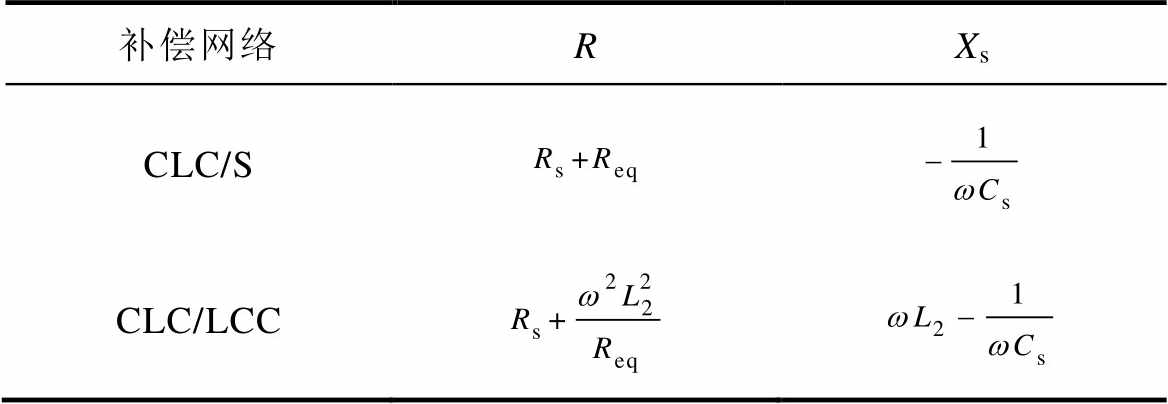
、 为中间变量;w 为系统工作角频率;Xs为副边的容抗;R为副边的总电阻,具体表达式见表1。
表1 R和Xs的表达式
Tab.1 Expressions for R、Xs
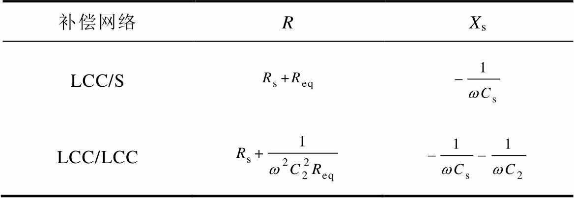
补偿网络RXs LCC/S LCC/LCC
由式(1)和式(2)可知,通过改变电容Cp,可使得bp-bpm=0成立。根据式(1),输入阻抗Zin则呈纯阻性,即表示原边处于谐振状态。
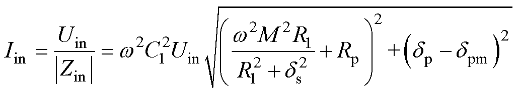
以LCC/LCC补偿网络为例,结合式(1)、式(2)、表1,可得系统输入阻抗模|Zin|和bp-bpm随参数bp的变化规律,如图3所示。根据式(2)可知,参数bs表示副边等效阻抗的虚部。从图3中可以看出,参数bs值的变化会导致bp-bpm=0谐振点的平移,意味着副边的阻抗会影响到原边的谐振状态。另外,当令bp-bpm=0时,系统输入阻抗模|Zin|将达到最大值。由图2可得,系统输入电流有效值Iin为
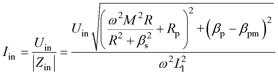 (3)
(3)
式中,Uin为输入电压的有效值。
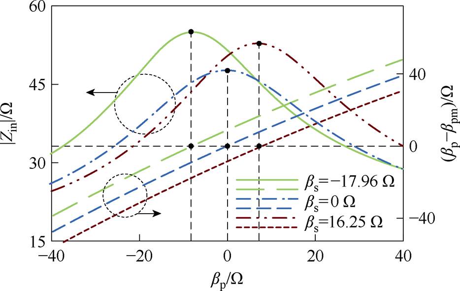
图3 不同参数bs下|Zin|和bp-bpm随参数bp的变化情况
Fig.3 Variation of |Zin| and bp-bpm with parameter bp at different bs
根据式(3),若bp-bpm=0,即输入阻抗模值|Zin|达到最大值时,系统输入电流有效值Iin将达到最 小值。
因此,对于原边LCC补偿的WPT系统,原边谐振需满足条件bp-bpm=0,其特征为电流有效值Iin达到最小值。
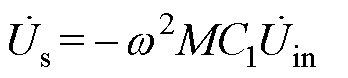
同样地,将系统原边电路折射到副边,其等效电路如图4所示,该等效电路将用于分析阻抗特性。其中,原边折射到副边的等效电压源 为
为
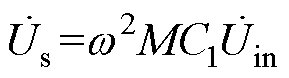 (4)
(4)
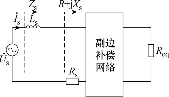
图4 副边等效电路
Fig.4 Equivalent circuit of the secondary-side
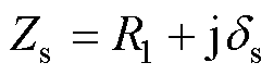
副边等效阻抗Zs为
 (5)
(5)
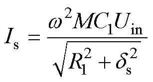
副边等效阻抗模|Zs|随参数bs的变化如图5所示。可以看出,当参数bs=0时,副边等效阻抗模|Zs|达到最小值,根据式(5)可知,此时Zs呈阻性,这意味着副边处于谐振状态。基于图4可知,副边电流有效值Is为
 (6)
(6)
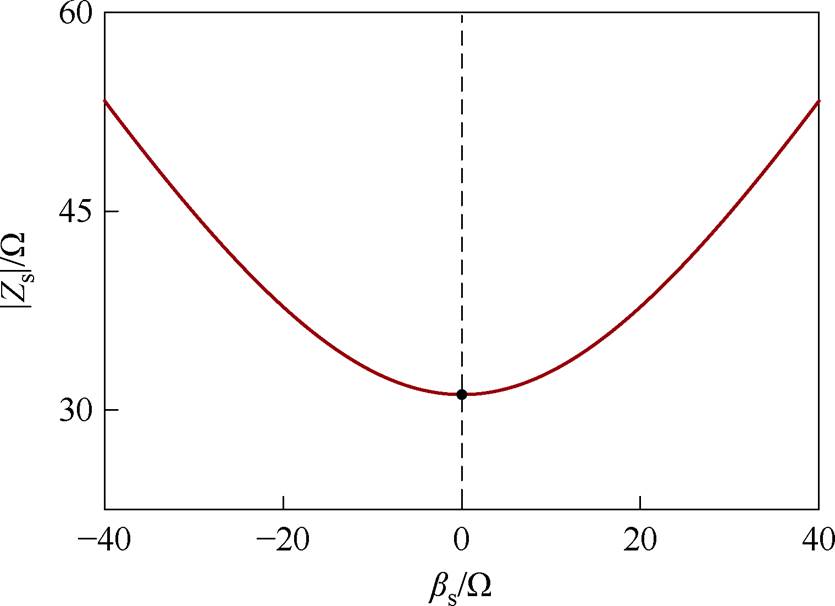
图5 |Zs|随bs的变化
Fig.5 |Zs| with the variation of bs
根据式(6),如果bs=0,即阻抗模|Zs|达到最小值,那么电流有效值Is将达到最大值。
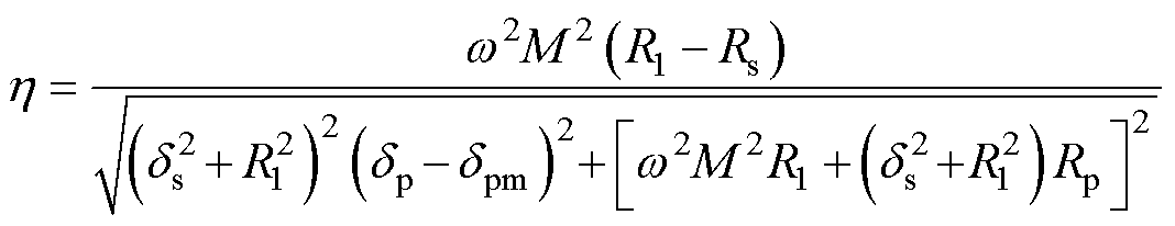
此外,根据图2所示等效电路,原边LCC补偿WPT系统的传输效率可描述为
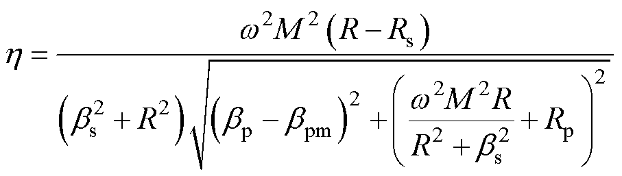 (7)
(7)
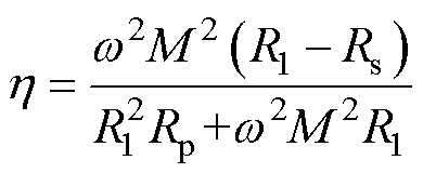
根据式(7),系统效率与bp-bpm和bs有关。由此分析,单边频率调谐不能消除耦合机构参数波动对系统效率的影响。在此基础上,若对双边进行频率调谐,使bp-bpm=0和bs=0,代入式(7)可得系统最优效率为
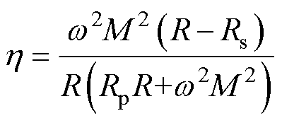 (8)
(8)
原边CLC补偿的WPT系统,譬如CLC/CLC和CLC/S补偿网络,如图1c和图1d所示。为简化分析过程,其等效电路如图6所示。
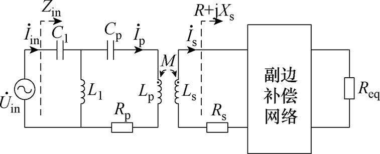
图6 原边CLC补偿的WPT系统
Fig.6 Primary-side CLC compensated WPT systems
同理,可推导系统输入阻抗Zin为
 (9)
(9)
其中
 (10)
(10)
式中, 为CLC/CLC和CLC/S补偿网络副边等效阻抗的虚部;
 、
、 为中间变量。R、Xs具体表达式见表2。
表2 R和Xs的表达式
Tab.2 Expressions for R、Xs
补偿网络RXs CLC/S CLC/LCC
由式(9)和式(10)可知,通过改变电容Cp值,可使得等式dp-dpm=0成立。根据式(9),输入阻抗Zin则呈纯阻性,即表示原边处于谐振状态。
以CLC/CLC补偿网络为例,结合式(9)、式(10)、表2,可得系统的输入阻抗模|Zin|和dp-dpm随参数dp的变化规律,如图7所示。从图7中可以看出,参数ds的变化会导致dp-dpm=0工作点的平移,意味着副边的阻抗值会影响到原边的谐振状态。当dp-dpm=0,系统输入阻抗模|Zin|达到最大值。根据图6,系统输入电流有效值Iin为
 (11)
(11)
根据式(11),若dp-dpm=0,即输入阻抗模值|Zin|达到最大值时,系统输入电流有效值Iin将达到最小值。
因此,对于原边CLC补偿的WPT系统,原边谐振需满足条件dp-dpm=0,其特征为电流有效值Iin达到最小值。
为了分析副边的阻抗特性,将原边电路折射到副边,等效电路同样可用图4表示。其中,原边折射到副边的等效电压源为
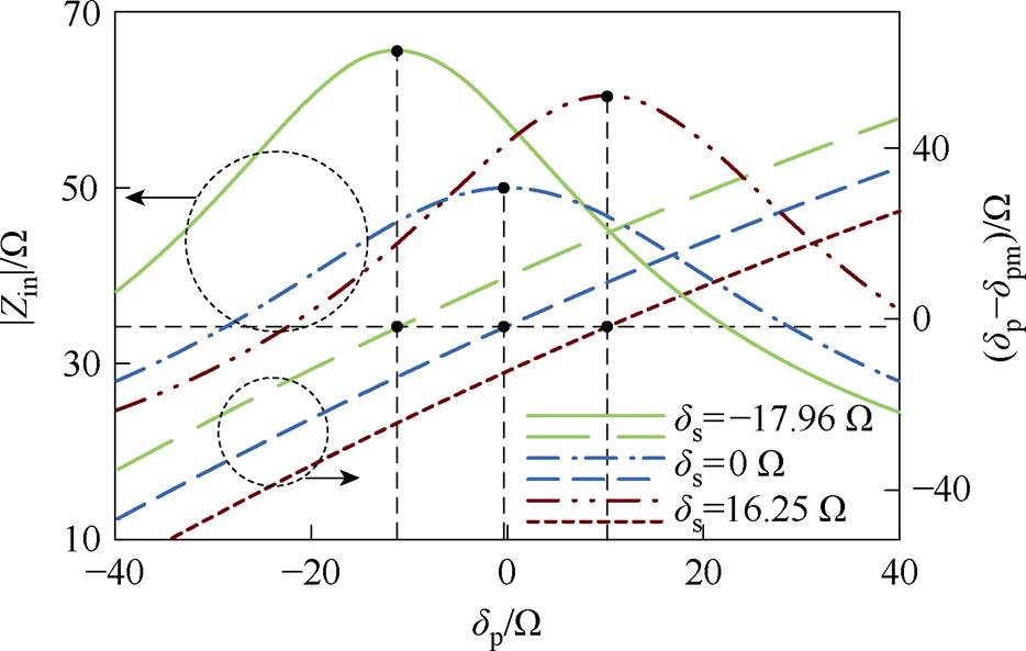
图7 不同参数ds下|Zin|和dp-dpm随参数dp的变化情况
Fig.7 Variation of |Zin| and dp-dpm with parameter dp
 (12)
(12)
副边等效阻抗Zs为
 (13)
(13)
同样以CLC/CLC补偿网络为例,结合式(9)、式(10)、表2,得到副边等效阻抗模|Zs|随参数ds的变化如图8所示。
图8 |Zs|随ds的变化
Fig.8 The variation of |Zs| with ds
可以看出,当参数ds=0时,副边等效阻抗模|Zs|达到最小值,且由式(13)可知Zs呈阻性,即表示副边处于谐振状态。同理,基于图4,副边电流有效值Is为
 (14)
(14)
根据式(14),如果bs=0,即阻抗模|Zs|达到最小值,那么电流有效值Is将达到最大值。
同样地,根据图6所示等效电路,原边CLC补偿WPT系统的传输效率可描述为
 (15)
(15)
根据式(15),系统效率与dp-dpm有关。由此分析,单边频率调谐不能消除耦合器参数波动对系统效率的影响。在此基础上,若对双边进行频率调谐,使dp-dpm=0和ds=0,代入式(15)可得系统最优效率为
 (16)
(16)
综上所述,可推导其他高阶补偿WPT系统的双边谐振条件及其特征,最终总结分析结果见表3。根据表3给出的分析结果,当双边谐振时,不同高阶补偿WPT系统具有相同的电气特征。譬如,当原边谐振时,系统输入电流有效值Iin达到最小值;副边谐振时,电流有效值Is达到最大值。
表3 高阶补偿WPT系统的双边谐振条件及其特征
Tab.3 Double-side resonant conditions and common features for high-order compensated WPT system
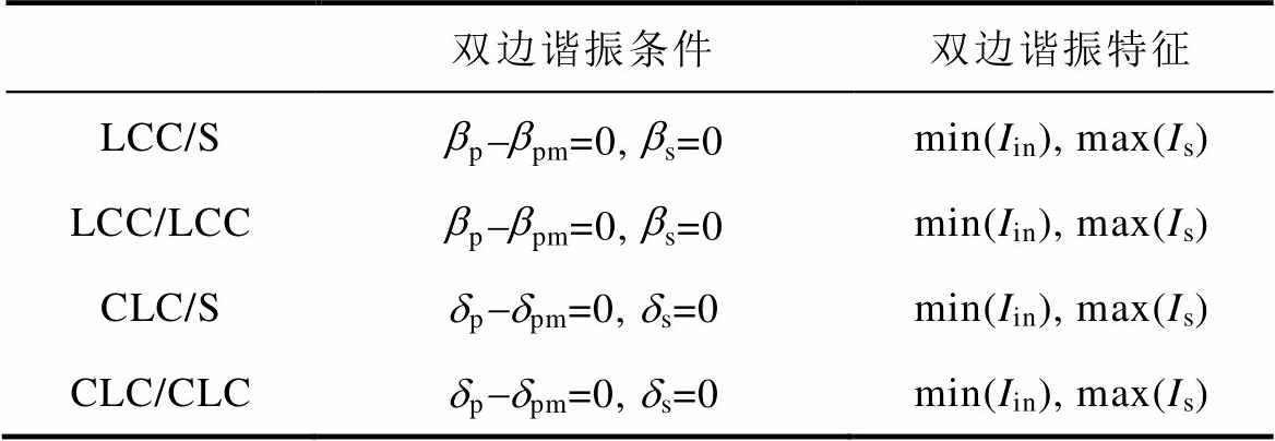
双边谐振条件双边谐振特征 LCC/Sbp-bpm=0, bs=0min(Iin), max(Is) LCC/LCCbp-bpm=0, bs=0min(Iin), max(Is) CLC/Sdp-dpm=0, ds=0min(Iin), max(Is) CLC/CLCdp-dpm=0, ds=0min(Iin), max(Is)
基于上述分析,提出了一种适于高阶补偿WPT系统的通用调谐解耦控制策略,即双边均采用扰动观察法来自动寻找各自的最优导通角,以满足最小电流min(Iin)和最大电流max(Is)的谐振特征,从而实现对高阶补偿WPT系统的双边自适应调谐控制。图9给出了LCC/LCC-WPT系统双边频率调谐控制系统框图。
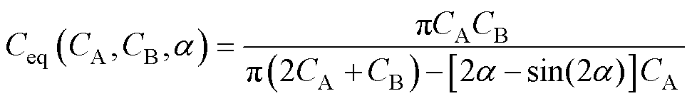
双边均采用SCC结构代替固有的补偿电容,当耦合机构参数漂移时,通过反馈控制PWM信号,调节开关电容转换器(Switched Capacitor Converter, SCC)的等效电容值Ceq,自动调整补偿网络参数,使系统双边谐振,保证系统高效传输及输出特性稳定。SCC等效电容值Ceq可表示[23]为

图9 双边调谐解耦控制LCC/LCC-WPT系统
Fig.9 Double-side frequency tuning decoupling control for LCC/LCC-WPT system
 (17)
(17)
式中,a 为控制信号的导通角,满足 ;CA、CB为SCC结构中的补偿电容。
由表3分析可知,可以通过搜索Iin的最小值找到bp-bpm=0。此外,由式(2)可知,bp-bpm与电容Cp有关,可以通过控制原边SCC导通角ap来改变Cp值。结合式(3)、式(17)和表1,可得Iin和bp-bpm随ap变化如图10所示。从图10中可以看出,当调整原边ap=apm时,bp-bp=0,表示原边处于谐振状态,电流Iin达到最小值。因此,原边调谐控制只需根据Iin的信息对Cp进行控制。
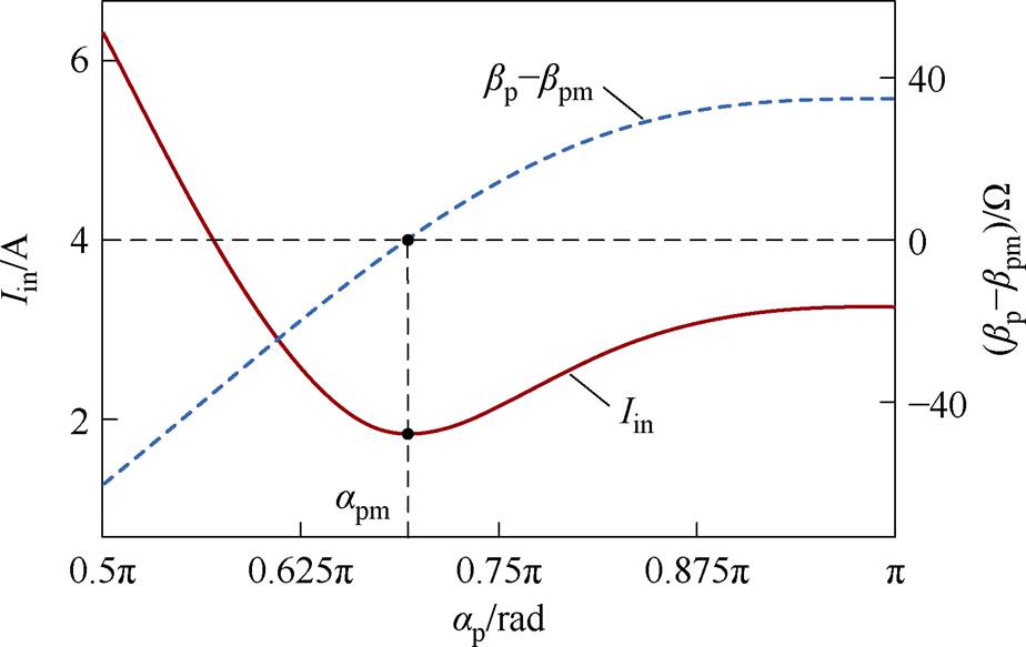
图10 bp-bpm与Iin随ap的变化
Fig.10 Changes of bp-bpm and Iin with ap
基于上述分析,提出采用扰动观察算法来寻找原边最优导通角apm,并且通过检测电流有效值Iin对SCC进行反馈控制,实现原边的自适应调谐。控制策略如图11所示,具体过程如下:
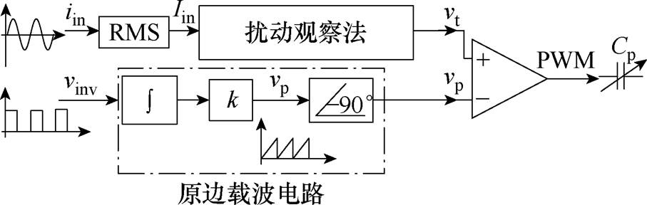
图11 原边调谐控制策略
Fig.11 Tuning control strategy of the primary-side
(1)实时采集系统输入电流iin并计算其有效值Iin,电流Iin经过扰动观察法处理后,生成调制信号vt。
(2)由理论分析知,L1、C1谐振时电流ip与电压uin存在如下关系
 (18)
(18)
可知ip滞后于uin相位90°,这种相位关系不受Cp或Cs变化的影响。为了使SCC的控制信号有效,它必须与流过开关电容的电流ip同步。因此,逆变驱动信号vinv(vinv与uin同步)作用于外部重置积分器,该积分器在外部信号的每个上升沿处被重置,由此可同步生成与vinv同频率的锯齿波信号vp。同时,可以通过信号vp滞后90°来生成与电流ip同步的载波信号 。
。
最后,调制信号vt与载波信号进行比较,用于生成控制原边SCC的PWM信号。
首先,根据表3分析可知,可以通过搜索Is的最大值来找到bs=0。此外,由式(2)可知,bs=0与电容Cs有关,可以通过控制副边SCC导通角as改变Cs值。结合式(6)、式(17)和表1,可得Is和bs随as的变化规律,如图12所示,从图12中可以看出,当控制as=asm使Is达到最大值时,即表示副边处于谐振状态。
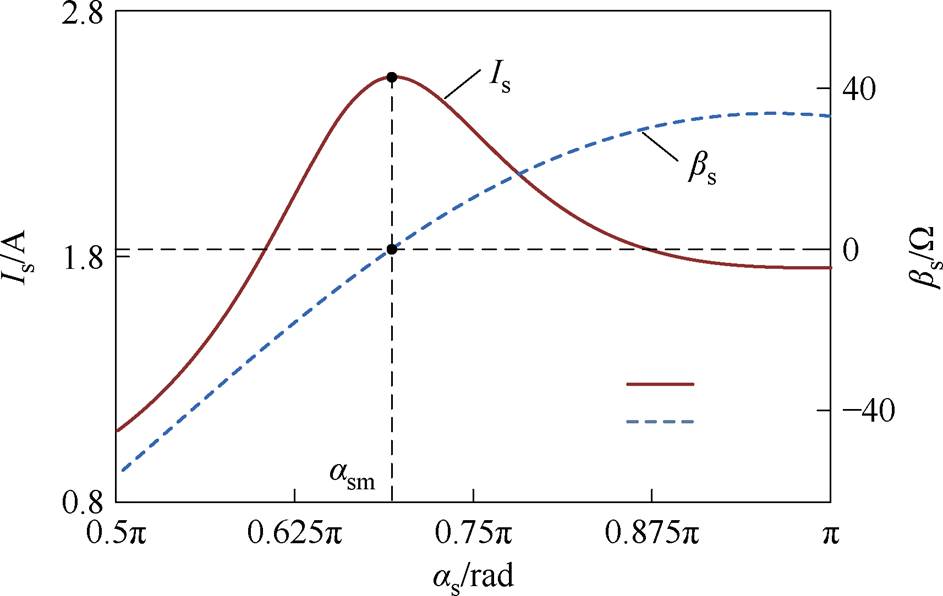
图12 bs与Is随as的变化
Fig.12 Changes of bs and Is with as
基于上述分析,副边线圈电流有效值Is经过扰动观察算法处理后生成调制信号vr。同时,电流Is通过载波电路处理,生成与is同步的载波信号vs,与图11中载波产生的原理类似。最后,将调制信号vr与载波信号vs进行比较,生成PWM信号来控制副边SCC。副边调谐控制策略如图13所示。
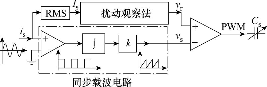
图13 副边调谐控制策略
Fig.13 Tuning control strategy of the secondary-side
基于上述双边调谐控制策略的分析,双边均可以采用扰动观察法来寻找各自的最优导通角。因此,双边的搜索过程如图14所示。
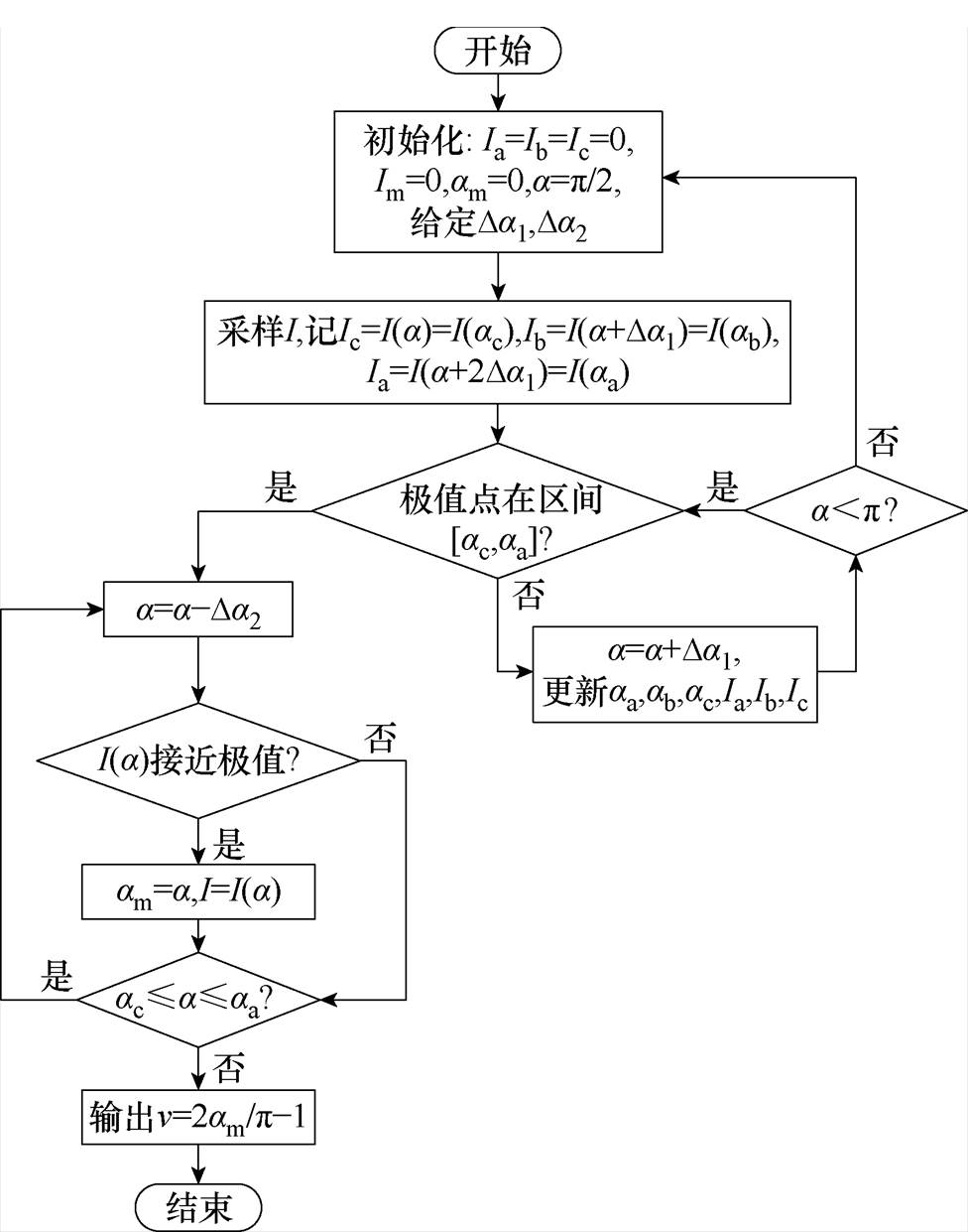
图14 扰动观察法流程
Fig.14 Flow chart of perturbation and observation method
首先,令导通角a 以大步长Da1增加,记相邻3次导通角输出值为aa、ab、ac,并且aa=ac+2Da1,ab=ac+Da1,对应的电流有效值为Ia、Ib、Ic。随着导通角以步长Da1增加,实时更新aa、ab、ac的值,且记录对应的Ia、Ib、Ic。
由于I作为导通角a 的函数只存在一个极值点(原边最小值,副边最大值)。当极值点出现在[ac, aa]区间时,最值电流对应的最优导通角必然存在于ac与aa之间。至此,导通角从aa开始以小步长Da2减小,最终确定与极值电流对应的am,搜索完成后基于式(19)输出调制信号。
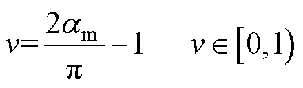 (19)
(19)
当双边达到谐振时有
 (20)
(20)
即uin与is同相可作为副边达到谐振的判断依据。
本文通过实验验证了理论分析的正确性和所提控制策略的有效性。根据图15所示双边调谐解耦LCC/LCC-WPT系统,搭建了180 W LCC/LCC WPT系统实验平台,通过调节双边SCC来完成调谐,从而达到所需的调谐目标,如图16所示。其中实验相关参数见表4。线圈为正六边形,利兹线线径为2 mm,匝数为23,外侧长度为18 cm,互感和自感为传输距离为10 cm且轴对称时的相应值。电子负载为IT8814,开关晶体管为CoolMOS SPW47N65C3,其导通电阻RDS(on)=70 mW。
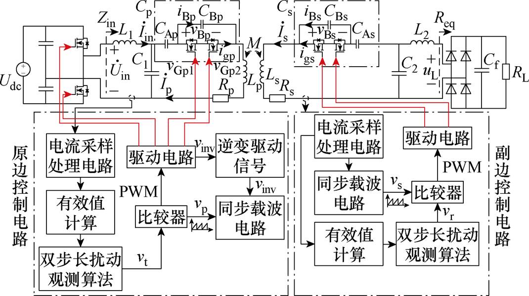
图15 双边调谐LCC/LCC-WPT系统
Fig.15 Double-side tuning of LCC/LCC-WPT System
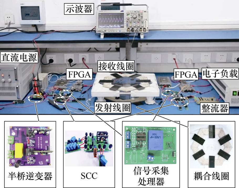
图16 双边调谐LCC/LCC-WPT系统实验平台
Fig.16 Experimental platform of double-side tuning LCC/LCC-WPT system
为了验证bp-bpm=0工作点会受到参数bs值的影响,在bs=-60.5 W 和bs=0 W 处的系统输入电流iin振幅进行了比较分析,原边谐振波形如图17所示。从图17可以看出,在不同的bs下,原边谐振时的输入电流iin振幅不同。特别是当bs=0时,电流iin振幅最大,这与图3中的分析结论一致。因此,验证了副边阻抗会影响原边的谐振状态。
表4 实验参数
Tab.4 Experimental parameters
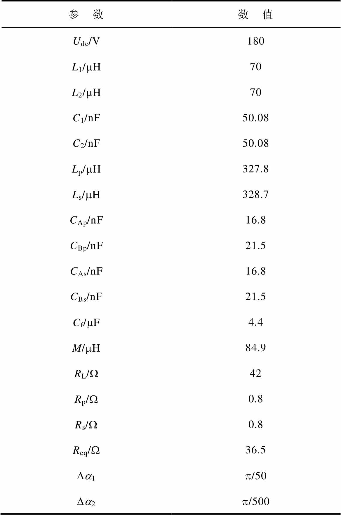
参 数数 值 Udc/V180 L1/mH70 L2/mH70 C1/nF50.08 C2/nF50.08 Lp/mH327.8 Ls/mH328.7 CAp/nF16.8 CBp/nF21.5 CAs/nF16.8 CBs/nF21.5 Cf/mF4.4 M/mH84.9 RL/W42 Rp/W0.8 Rs/W0.8 Req/W36.5 Da1p/50 Da2p/500
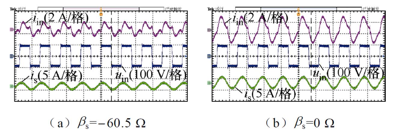
图17 不同bs取值下原边谐振波形
Fig.17 Experimental waveforms of primary-side resonance under different bs
为了验证高阶补偿WPT系统具有最小电流Iin和最大电流Is的谐振特征,在不同偏移工况下,双边SCC的导通角a 从0.5p 以大步长Da1增加到p,并记录电流Iin和Is的变化,根据所记录的数据拟合如图18所示,图中D为传输距离,r 为沿x轴方向的偏移距离。
由图18可知,在不同偏移情况下,系统输入电流有效值Iin有最小值,副边线圈电流有效值Is有最大值。实验结果与第1节理论分析结论吻合,验证了高阶补偿WPT系统双边谐振共同特征的正确性。
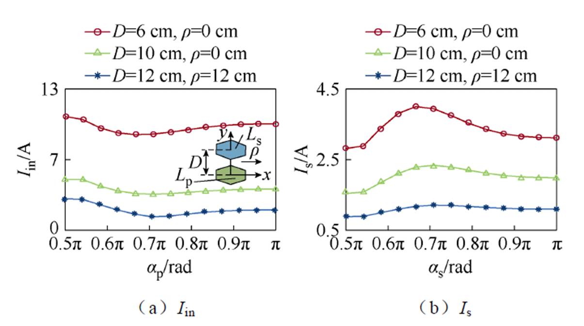
图18 电流Iin和Is随导通角变化趋势
Fig.18 Trend of currents Iin and Is with conduction angles
当线圈相对位置为D=10 cm,r=0 cm时,对所提控制策略适用于不同高阶补偿WPT的有效性进行了实验。在无通信的情况下,LCC/LCC-WPT系统和LCC/S-WPT系统双边达到谐振时的瞬态波形如图19所示。
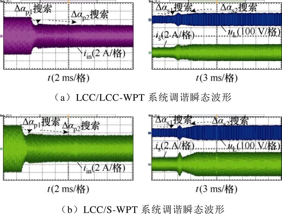
图19 原边LCC补偿的WPT系统调谐过程实验波形
Fig.19 Experimental waveforms of tuning process of WPT system with primary-side LCC compensation
由图19可知,原边LCC补偿的WPT系统的输入电流iin和接收线圈电流is都经历两个阶段:第一阶段为大步长Da1搜索过程,快速确定最优导通角范围;第二阶段为小步长Da2搜索过程,精确寻找apm和asm。系统输入电流iin逐渐达到最小值,接收线圈电流is逐渐达到最大值,表示双边最终达到谐振。与理论分析的搜索过程符合。
在不同传输距离下,对LCC/LCC-WPT系统进行无调谐、原边调谐以及双边调谐控制,对比了在耦合机构水平偏移工况下的传输效率,如图20所示。
结果表明,随着耦合机构偏移距离的增加,系统传输效率逐渐降低,且偏移距离越远,效率下降越明显。值得注意的是,相对于无调谐系统,有调谐系统的传输效率显然更高。此外,双边调谐控制的系统传输效率比原边调谐的系统要高。在传输距离分别为8 cm和10 cm时,原边调谐控制最大只能分别提升2.85%和1.88%的效率,双边调谐控制最大分别能够提升4.21%和2.91%的效率,双边调谐系统最大传输效率达到了93.1%。证明了在偏移情况下,对WPT系统进行双边调谐控制的必要性。
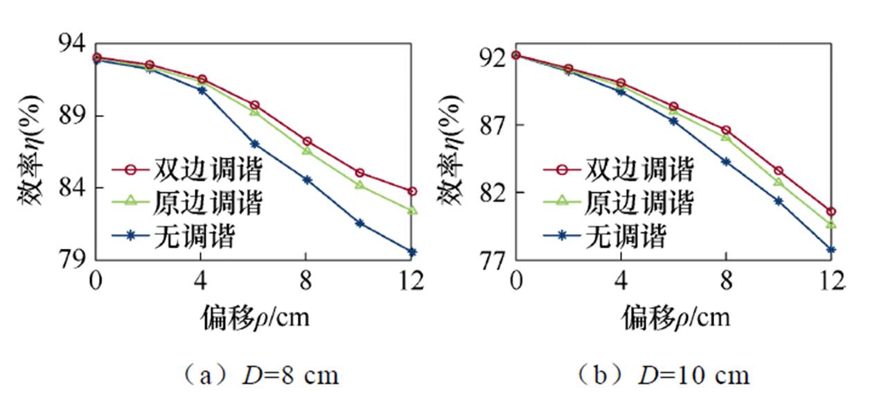
图20 不同传输距离下传输效率受偏移工况的影响
Fig.20 Experimental comparison of transmission efficiency affected by misalignment at different transmission distances
表5为系统在输出功率为55 W,D=6 cm和r= 10 cm工况下的功率损耗分析。该工况下,原边MOS管的电流有效值为4.61 A,副边MOS管的电流有效值为1.88 A。由于PWM型SCC的开关管实现了软开关[18],因此能耗主要来源于开关管的导通损耗。
表5 功率损耗分析
Tab.5 Analysis of power loss (单位: W)
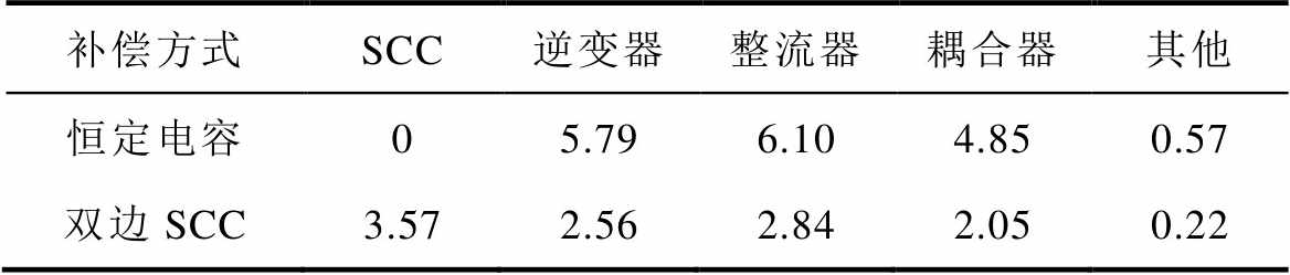
补偿方式SCC逆变器整流器耦合器其他 恒定电容05.796.104.850.57 双边SCC3.572.562.842.050.22
与系统失谐时补偿电容恒定时相比,双边采用SCC结构虽然增加了4个开关管和2个电容,总功率损耗为3.57 W。然而,通过双边调谐,逆变器损耗降低了3.23 W,整流器损耗降低了3.26 W,耦合器损耗降低了2.8 W,最终系统效率提升了6.98%。
为提升双边频率调谐控制方法的普适性和自适应性,本文提出了一种适用于高阶补偿WPT系统的通用调谐解耦控制策略,具有普适性和自适应性等优势。研究结果表明,该方法能有效抑制因耦合机构参数漂移和线圈自感波动而引起的频率失谐问题,可有效提升WPT系统的传输效率和稳定性。此外,所提方法同样适用于p 型补偿网络的高阶WPT系统。考虑到实时性要求,所提调谐策略较适用于高阶WPT系统的静态无线充电应用场景,未来可进一步探讨适用于动态无线充电场合的调谐解耦控制方法。
参考文献
[1] 杨庆新, 张献, 章鹏程. 电动车智慧无线电能传输云网[J]. 电工技术学报, 2023, 38(1): 1-12.
Yang Qingxin, Zhang Xian, Zhang Pengcheng. Intelligent wireless power transmission cloud network for electric vehicles[J]. Transactions of China Elec- trotechnical Society, 2023, 38(1): 1-12.
[2] 徐先峰, 吴慧玲, 杨雄政, 等. 空间约束下电动汽车无线充电系统磁耦合结构优化[J]. 电工技术学报, 2024, 39(12): 3581-3588.
Xu Xianfeng, Wu Huiling, Yang Xiongzheng, et al. Optimization of magnetically coupled structure of wireless charging system for electric vehicles under space constraint[J]. Transactions of China Electro- technical Society, 2024, 39(12): 3581-3588.
[3] 陈志鑫, 张献, 沙琳, 等. 基于频率调节的电动汽车无线充电互操作性提升方法研究[J]. 电工技术学报, 2023, 38(5): 1237-1247.
Chen Zhixin, Zhang Xian, Sha Lin, et al. Research on improving interoperability of electric vehicle wireless power transfer based on frequency adjustment[J]. Transactions of China Electrotechnical Society, 2023, 38(5): 1237-1247.
[4] 田勇, 冯华逸, 田劲东, 等. 电动汽车动态无线充电系统输出电流模型预测控制[J]. 电工技术学报, 2023, 38(9): 2310-2322, 2447.
Tian Yong, Feng Huayi, Tian Jindong, et al. Model predictive control for output current of electric vehicle dynamic wireless charging systems[J]. Transa- ctions of China Electrotechnical Society, 2023, 38(9): 2310-2322, 2447.
[5] 吴旭升, 孙盼, 杨深钦, 等. 水下无线电能传输技术及应用研究综述[J]. 电工技术学报, 2019, 34(8): 1559-1568.
Wu Xusheng, Sun Pan, Yang Shenqin, et al. Review on underwater wireless power transfer technology and its application[J]. Transactions of China Electro- technical Society, 2019, 34(8): 1559-1568.
[6] Liu Xun, Hui S Y. Simulation study and experimental verification of a universal contactless battery charging platform with localized charging features[J]. IEEE Transactions on Power Electronics, 2007, 22(6): 2202-2210.
[7] 蔡瑞佳, 马运东, 王鹏飞, 等. 基于双向半桥CLLLC谐振变换器的锂电池均衡电路[J]. 电工技术学报, 2024, 39(15): 4868-4882.
Cai Ruijia, Ma Yundong, Wang Pengfei, et al. Lithium- ion battery equalization circuit based on bidirectional half-bridge CLLLC resonant converter[J]. Transa- ctions of China Electrotechnical Society, 2024, 39(15): 4868-4882.
[8] 周玮, 郑宇锋, 陈泽林, 等. 基于副边解耦极板的电容式无线电能传输系统拾取端失谐评估[J]. 电力系统自动化, 2024, 48(3): 142-149.
Zhou Wei, Zheng Yufeng, Chen Zelin, et al. Detuning estimation of pickup loop in capacitive wireless power transfer system based on secondary-side decoupled capacitive coupler[J]. Automation of Electric Power Systems, 2024, 48(3): 142-149.
[9] 贾金亮, 闫晓强. 磁耦合谐振式无线电能传输特性研究动态[J]. 电工技术学报, 2020, 35(20): 4217- 4231.
Jia Jinliang, Yan Xiaoqiang. Research tends of magnetic coupling resonant wireless power transfer characteristics[J]. Transactions of China Electro- technical Society, 2020, 35(20): 4217-4231.
[10] Fu Wenzhen, Zhang Bo, Qiu Dongyuan. Study on frequency-tracking wireless power transfer system by resonant coupling[C]//2009 IEEE 6th International Power Electronics and Motion Control Conference, Wuhan, 2009: 2658-2663.
[11] Su Yugang, Chen Long, Wu Xueying, et al. Load and mutual inductance identification from the primary side of inductive power transfer system with parallel- tuned secondary power pickup[J]. IEEE Transactions on Power Electronics, 2018, 33(11): 9952-9962.
[12] Tang Chunsen, Dai Xin, Wang Zhihui, et al. Frequ- ency bifurcation phenomenon study of a soft switched push-pull contactless power transfer system[C]//2011 6th IEEE Conference on Industrial Electronics and Applications, Beijing, China, 2011: 1981-1986.
[13] 刘帼巾, 李义鑫, 崔玉龙, 等. 基于FPGA的磁耦合谐振式无线电能传输频率跟踪控制[J]. 电工技术学报, 2018, 33(14): 3185-3193.
Liu Guojin, Li Yixin, Cui Yulong, et al. Frequency tracking control of wireless power transfer via magnetic resonance coupling based on FPGA[J]. Transactions of China Electrotechnical Society, 2018, 33(14): 3185-3193.
[14] Kim D H, Ahn D. Self-tuning LCC inverter using PWM-controlled switched capacitor for inductive wireless power transfer[J]. IEEE Transactions on Industrial Electronics, 2019, 66(5): 3983-3992.
[15] Chowdhury S A, Kim S W, Kim S M, et al. Automatic tuning receiver for improved efficiency and EMI suppression in spread-spectrum wireless power transfer[J]. IEEE Transactions on Industrial Elec- tronics, 2023, 70(1): 352-363.
[16] Li Weihan, Wei Guo, Cui Chao, et al. A double-side self-tuning LCC/S system using a variable switched capacitor based on parameter recognition[J]. IEEE Transactions on Industrial Electronics, 2021, 68(4): 3069-3078.
[17] Li Weihan, Zhang Qianfan, Cui Chao, et al. A self- tuning S/S compensation WPT system without parameter recognition[J]. IEEE Transactions on Industrial Electronics, 2022, 69(7): 6741-6750.
[18] Tan Ping’an, Song Bin, Lei Wang, et al. Decoupling control of double-side frequency tuning for LCC/S WPT system[J]. IEEE Transactions on Industrial Electronics, 2023, 70(11): 11163-11173.
[19] Song Kai, Yang Guang, Zhang Hang, et al. An impedance decoupling-based tuning scheme for wireless power transfer system under dual-side capacitance drift[J]. IEEE Transactions on Power Electronics, 2021, 36(7): 7526-7536.
[20] Zhang Jianzhong, Zhao Jin, Zhang Yaqian, et al. A wireless power transfer system with dual switch- controlled capacitors for efficiency optimization[J]. IEEE Transactions on Power Electronics, 2020, 35(6): 6091-6101.
[21] Lu Jianghua, Zhu Guorong, Lin Deyan, et al. Load- independent voltage and current transfer characte- ristics of high-order resonant network in IPT system[J]. IEEE Journal of Emerging and Selected Topics in Power Electronics, 2019, 7(1): 422-436.
[22] Tan Pingan, Peng Tao, Gao Xieping, et al. Flexible combination and switching control for robust wireless power transfer system with hexagonal array coil[J]. IEEE Transactions on Power Electronics, 2021, 36(4): 3868-3882.
[23] Hu Zhiyuan, Qiu Yajie, Wang Laili, et al. An inter- leaved LLC resonant converter operating at constant switching frequency[C]//2012 IEEE Energy Con- version Congress and Exposition (ECCE), Raleigh, NC, USA, 2012: 3541-3548.
Abstract As a non-contact power supply method, wireless power transfer (WPT) technology is widely used in medical, automotive, and cellular devices because of its reliability, safety, and high degree of freedom. However, the parameter drift phenomenon of the coupler inevitably occurs in practical applications, which leads to the fluctuation of self-inductance and makes the WPT system suffer from frequency detuning. Thus, its transmission characteristics and stability are affected. Traditional bilateral frequency tuning methods are non-uniform because of the type of topology, and some require communication equipment and complex optimization of control parameters. This paper proposes a unified decoupling control strategy of frequency tuning for high-order compensated WPT systems.
Four T-type higher-order compensation networks of LCC/LCC, LCC/S, CLC/CLC, and CLC/S are analyzed as examples. Based on the impedance model, the bilateral resonance characteristics of the primary-side LCC-compensated WPT system and the primary-side CLC-compensated WPT system are deduced. If the primary side is in a resonant state, the RMS value of the input current will reach the minimum. If the secondary side is in a resonant state, the RMS value of the current will reach the maximum. Finally, the generalized criterion is obtained for bilateral tuning decoupling control of higher-order compensated WPT systems.
This paper proposes a control strategy to realize the bilateral tuning decoupling control without communication or parameter identification. Instead of the inherent compensation capacitance, the switched capacitor converter (SCC) structure is used, and the equivalent capacitance of the SCC is varied by changing the conduction angle of the control signal. Based on the generalized tuning criterion, the conduction angle of the SCC control signal is changed with the help of the double-step perturbation observation method, and the primary and secondary currents are searched until the minimum value of the primary input current and the maximum value of the secondary coil current. Therefore, the WPT system reaches the resonant state while the conduction angle is optimal. The primary and secondary resonance parameters are realized independently and adaptively, and the bilateral tuning and decoupling control is achieved.
Finally, an experimental prototype of a 180 W LCC/LCC WPT system is built. The experimental results are consistent with the theoretical analysis, verifying the effectiveness of the proposed generalized tuning decoupling control strategy. The results show that the method can effectively suppress the frequency detuning problem caused by the parameter drift of the coupler and the self-inductance fluctuation, improving the transmission efficiency and stability of the WPT system. In addition, the proposed method is applicable to the high-order WPT system with a π-type compensation network.
keywords:Decoupling control, frequency tuning, parameter fluctuation, wireless power transfer (WPT)
中图分类号:TM724
DOI: 10.19595/j.cnki.1000-6753.tces.240629
湖南省教育厅科学研究基金资助项目(22C0069)。
收稿日期 2024-04-23
改稿日期2024-07-10
谭平安 男,1979年生,博士,教授,硕士生导师,研究方向为无线电能传输、电力电子系统与控制等。
E-mail: tanpingan@126.com(通信作者)
周睿洋 男,2000年生,硕士研究生,研究方向为无线电能传输。
E-mail: zhouruiyang369@163.com
(编辑 陈 诚)