 、
、 、
、 为网侧三相电压,
 、
、 、
、 为网侧三相电流,
 、
、 、
、 为交流电网电压,
 、
、 为滤波参数,
 为线路等效电阻参数,ir为电池电流,
 为直流母线电压,
 为母线电流,iL为DC-DC变换器电感电流,io为直流侧输出电流,
 、
、 分别为储能侧电感、电容。
摘要 针对传统控制策略下两级式储能变流器功率变化时的暂态性能差和直流母线电压波动大的问题,该文设计了一种基于有限时间观测器的滑模自抗扰控制(ADRC)策略,并将该控制策略应用于变流器的功率控制和双向DC-DC变换器的直流母线电压控制中以提高系统的暂态性能。首先,该控制策略以自抗扰控制(ADRC)为基础,将变流器之间的耦合部分归入集总扰动中,通过有限时间观测器快速、精准地估计扰动,并将扰动估计值通过前馈补偿以提高控制器的解耦能力;其次,采用基于改进的变速趋近律和积分滑模设计反馈控制律以提高误差的收敛速度和抗扰性能;再次,根据Lyapunov理论证明了该文控制的稳定性和有限时间收敛性;最后,进行了仿真及实验验证。结果表明,该文所提控制策略较PI控制和ADRC策略具有更好的解耦效果,并减小了并网电流谐波,提高了系统暂态响应能力。
关键词:两级式储能变流器 有限时间观测器 自抗扰控制 积分滑模 StarSim
近年来,由于化石能源的广泛使用导致能源短缺和环境问题日益加剧,在此背景下我国于2020年提出“双碳”目标[1],研究人员将更多的目光投向光伏、风电等清洁能源。由于光照、风力的随机波动性会造成其发出的电能也具有波动性,因此在建设电站时一般建设为光储、风储电站(即配备储能系统),来提高供电可靠性[2-3]。储能系统的核心部分是储能变流器(Power Conversion System, PCS),常用的储能变流器有单级式和两级式[4]。其中单级式PCS结构简单,控制策略相对容易实现。但是对储能电池数量需求多,电池管理难度大,对电池组电压的升降控制功能欠缺。在单级式PCS的前级直流侧增加双向Buck/Boost变换器构成两级式PCS可提高储能系统应用的电压等级[5]。另外,两级式PCS通过增加的双向DC-DC变换器来控制储能电池的充、放电,还可以保证直流母线电压的稳定运行,提高系统可靠性,进而保障新能源发电能够可靠地起到源荷平衡、削峰填谷的作用[6-7]。在两级式PCS中,双向DC-DC变换器和双向DC-AC变流器是整个系统的关键部分,该部分能否可靠运行直接影响储能系统能否可靠工作,因此设计合适的控制策略对系统可靠运行至关重要[8]。目前储能系统中多将PI控制应用于PCS中,但是PI控制也有如超调大、响应慢等不足[9-10],可能无法达到理想的效果。
因此,众多学者将目光转向模糊控制、模型预测控制、自抗扰控制(Active Disturbance Rejection Control, ADRC)和滑模控制等性能更好的非线性控制。这些控制方法中模糊控制和模型预测控制在处理非线性模型的同时,也带来了一些如计算量大、训练次数多、依赖模型和主观经验等问题[11]。而以扩张状态观测器为基础的自抗扰控制不需要精确的数学模型,并且抗扰性能较好,在非线性系统中应用前景良好[12],滑模控制也因鲁棒性强、收敛快而应用广泛[13]。文献[14]将自抗扰控制应用于小型压水堆稳压器,实现了控制对象变量之间的解耦,提高了系统的鲁棒性。文献[15]提出一种无人直升机的自抗扰控制,提高了系统的暂态性能及对环境的适应能力。文献[16]在微网逆变器的电压控制中应用基于改进型趋近律的滑模控制,降低了滑模运动的抖振,提高了误差的收敛速度。文献[17]提出一种将滑模和ADRC复合的控制策略应用于电机中,起到了较好的解耦效果,同时改善了抗扰性。
考虑到储能变流器的非线性和强耦合性等特点,以及滑模和ADRC的优势,本文采用收敛速度更快的有限时间观测器设计了一种积分滑模自抗扰控制策略,该控制策略以ADRC为控制器主体,将有限时间观测器和滑模控制引入ADRC以提高观测器的扰动估计能力和反馈控制的误差收敛速度,进而提高整个控制系统的暂态响应能力。
两级式PCS的主电路结构如图1所示,由储能系统经过双向DC-DC变换器输出稳定的直流电压,通过控制后级变流器输出一定的功率来供给交流负载使用。当变流器输出的功率多于负载所需时,则多余的部分可并网使用;反之,当变流器输出功率不足以满足负载所需时,则功率差额由电网提供。另外,当处于负荷低谷时,可由交流侧通过变流器向储能系统充电以实现电能的高效利用。对变流器的控制采用恒功率控制(PQ控制),分别对有功功率无功功率设置参考值,通过控制策略使变流器分别恒定地输出相应的功率。
图1中、、为网侧三相电压,、、为网侧三相电流,、、为交流电网电压,、为滤波参数,为线路等效电阻参数,ir为电池电流,为直流母线电压,为母线电流,iL为DC-DC变换器电感电流,io为直流侧输出电流,、分别为储能侧电感、电容。
由图1可推导出后级变流器在 坐标系下的状态方程为
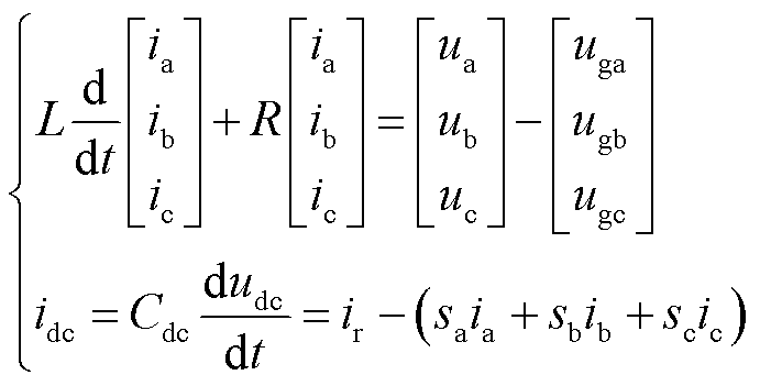 (1)
(1)
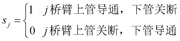
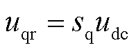
式中,sj(j=a,b,c)为变流器中开关管通断状态,具体为
 (2)
(2)
为了方便控制器设计,将式(1)转换到dq坐标系下,得到的微分方程为
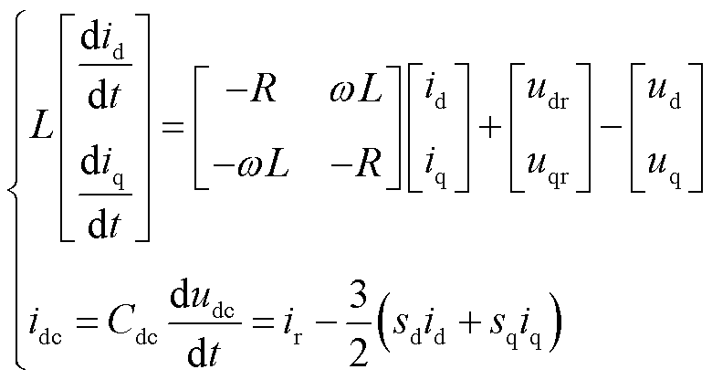 (3)
(3)
式中, 为电网电压角频率;
 ,
, ;
; 、
、 为开关函数在dq轴上的分量;
 、
、 为电网电压在dq轴上的分量;
 、
、 为网侧电流在dq轴的分量。
在三相对称的电网电压下,可得到交流侧瞬时功率为
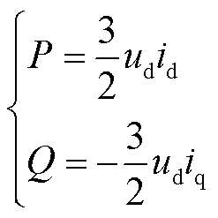 (4)
(4)
由式(4)可计算出dq轴电流与功率的关系式为
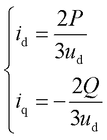 (5)
(5)
由图1可知前级变换器的结构。uin为储能电池的放电电压,同时也是前级变换器的输入电压,VT1、VT2为DC-DC模块功率开关管,VT1、VT2互补导通。
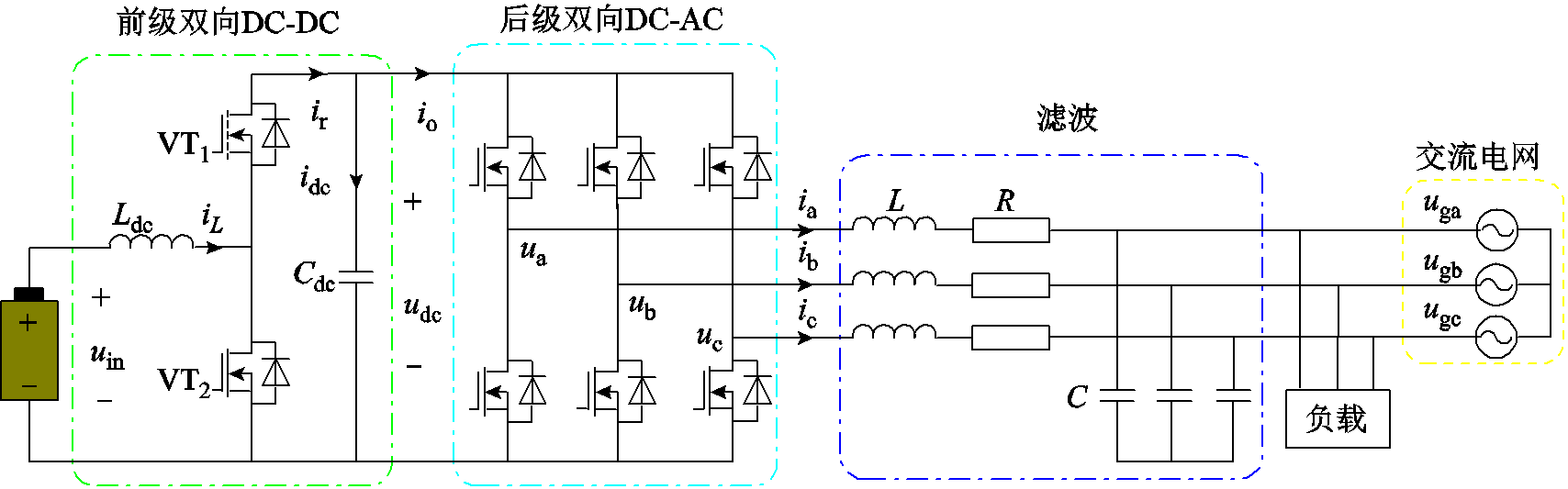
图1 两级式储能变流器主电路
Fig.1 Main circuit of two-stage power conversion system
当开关管VT1导通VT2关断时,DC-DC变换器工作在Buck模式;当开关管VT1关断VT2导通时,变换器工作在Boost模式。根据状态空间平均法可得DC-DC模块的状态方程为
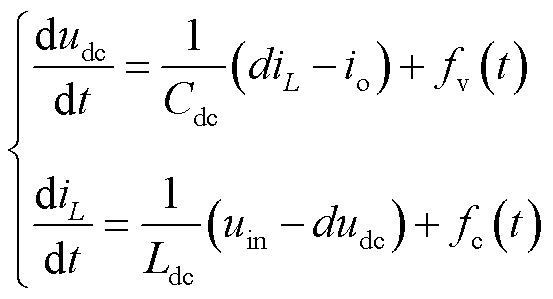 (6)
(6)
式中,fv(t)、fc(t)分别为电压、电流的未知扰动;d为开关管的占空比。
PQ控制包括功率外环和电流内环,外环可通过式(4)计算得出电流内环参考值idref、iqref,然后由式(3)微分方程设计电流内环控制律控制PCS输出的功率。
由式(3)、式(4)可知,功率P、Q与id、iq具有直接关系,且id、iq具有耦合性。本文采用的恒功率控制的实质是对功率实现解耦控制,然后对有功和无功功率分别控制。为了简化控制器的复杂度,以ADRC的框架来设计控制器,将式(3)转换成ADRC的范式为
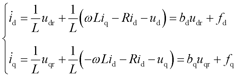 (7)
(7)
式中,bd、bq为控制量增益;fd、fq为等效后的包括系统未建模部分、耦合部分以及系统内外扰动的集总扰动,其表达式为
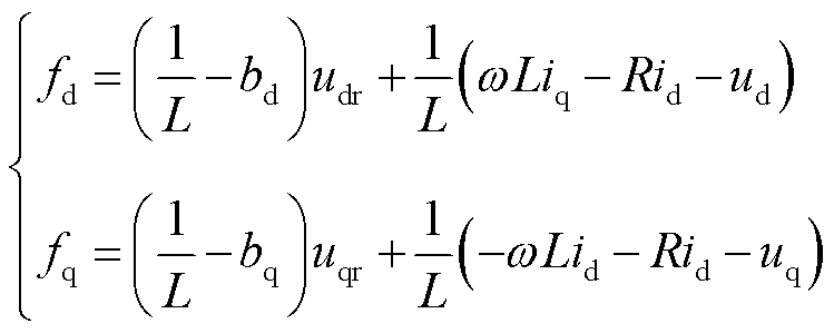 (8)
(8)
令状态变量xd1=id,xd2=fd,xq1=iq,xq2=fq,则式(7)可写为
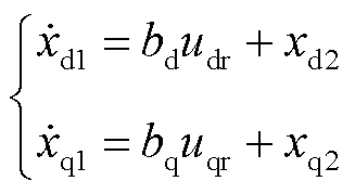 (9)
(9)
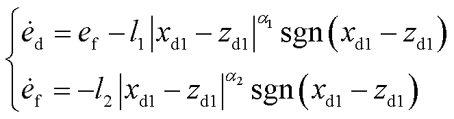
根据式(9)可设计有限时间观测器的形式为
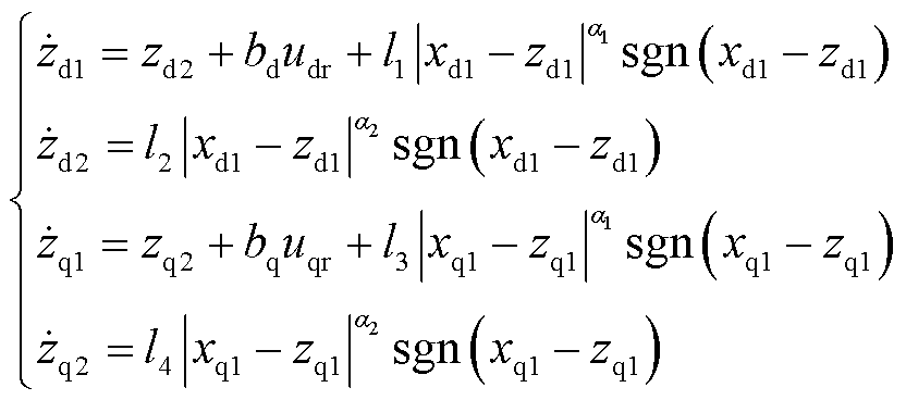 (10)
(10)
式中,sgn(·)为符号函数;l1~l4为观测器增益,且大于零;0.5<α1<1,α2=2α1-1;zd1、zd2、zq1、zq2分别为xd1、xd2、xq1、xq2的观测值。
设e1、e2为id、iq与参考值之间的偏差,有
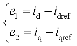 (11)
(11)
为使控制量能快速平滑地跟踪期望值,且在扰动下也具有良好的控制精度和稳定性,根据式(11)的偏差构造积分滑模函数[18]为
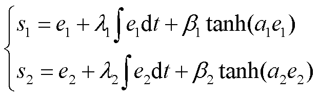 (12)
(12)
式中,λ1,2≥0,β1,2≥0,a1,2≥0。
令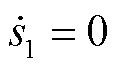 ,
, ,并将其与式(7)联立可得等效控制律为
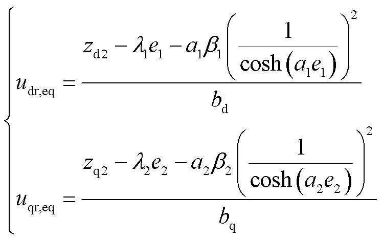 (13)
(13)
式(13)得出的控制律可以使系统的控制轨迹运动在式(12)的滑模面上,同时还要有切换控制律控制被控对象的状态轨迹不离开滑模面运动。
切换控制律一般由滑模趋近律充当,常用的有等速趋近律、指数趋近律等,但是等速趋近律趋近速度较慢,而指数趋近律则会产生较大的抖振[19]。故采用改进型的复合变速趋近律作为本文滑模自抗扰的切换控制律,趋近律的形式为[16]
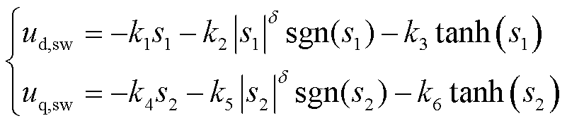 (14)
(14)
式中,δ为自适应变速参数,其表达式为
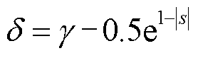 (15)
(15)
式中, >1,本文中取=1.5。
由式(15)可知δ可根据系统的滑模函数做出自适应变化,当被控对象运动轨线离平衡点较远(即 较大)时,δ的取值增大,以保证滑模趋近运动的速度;当运动轨线离平衡点的距离较近时,δ取较小值以削弱趋近运动中的抖振现象。
因此,可得到后级变流器综合控制律为
 (16)
(16)
综上所述,可得到后级变流器的控制框图如图2所示。
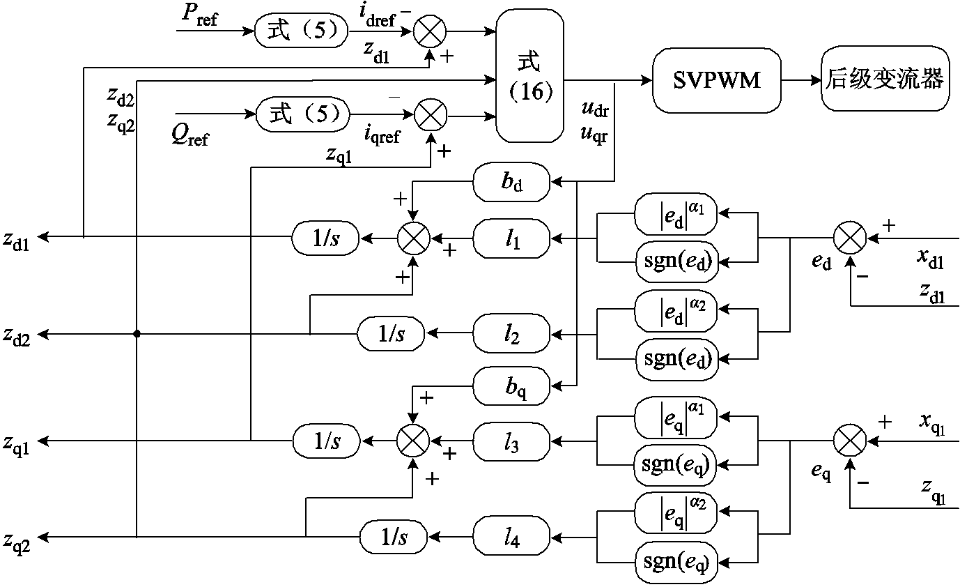
图2 后级变流器控制框图
Fig.2 Control block diagram of the rear converter
前级DC-DC变换器采用电压、电流双环控制以提高系统的控制精度和扰动抑制能力。电压外环亦采用改进后滑模自抗扰控制,通过有限时间观测器估计系统不确定部分,将其估计值用于扰动补偿,在反馈控制中采用改进积分滑模以提高控制器的响应速度和抗扰能力。电压外环的控制目的是为电流内环提供参考值,故电压外环的控制量为电感电流。
将式(6)中电压方程转换成ADRC范式为
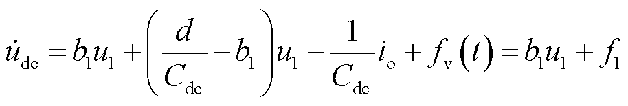 (17)
(17)
式中,b1为电压环控制量增益;u1为电压环控制量;f1为除控制输入之外的等效集总扰动。
令状态变量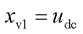 ,
,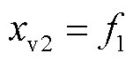 ,则电压外环观测器形式为
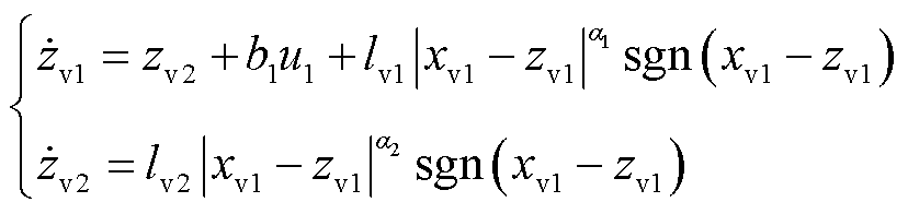 (18)
(18)
式中,电压外环观测器增益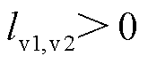 ;zv1、zv2分别为xv1、xv2的观测值。
设双向DC-DC变换器输出电压参考值为udcref,则输出电压与参考值之间的电压偏差ev为
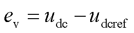 (19)
(19)
对式(19)求导可得电压偏差微分为
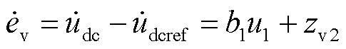 (20)
(20)
联立式(19)、式(20)设计电压环积分滑模函数为
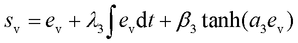 (21)
(21)
选取电压外环滑模反馈趋近律为
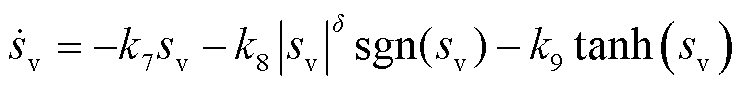 (22)
(22)
联立式(17)~式(22)可得外环控制律为
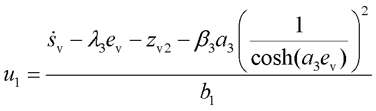 (23)
(23)
因外环为电流内环提供参考,所以电感电流的参考值iLref = u1。由上述电压外环的设计过程可得到如图3所示的电压外环控制框图。
电流内环以DC-DC模块中电感电流iL为状态变量,根据iL与上述电压外环中式(23)得到的iLref之间的电流偏差为基础设计控制器,得到最终通入DC-DC变换器的控制信号(即占空比d),进而保证DC-DC模块的稳定运行。电流内环控制器设计过程与电压外环设计过程相同,采用的方法也与电压外环相同,并且在仿真过程中采用的参数也一致,故在此不再赘述。
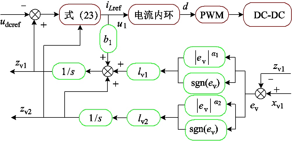
图3 DC-DC变换器电压外环控制框图
Fig.3 DC-DC converter voltage outer loop control block diagram
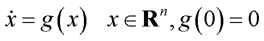
考虑非线性系统为
 (24)
(24)
该系统满足Lipschitz连续条件。
定义1[20]:若g(x)在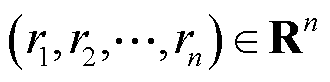 、1≤i≤n且对任意λ>0时,满足
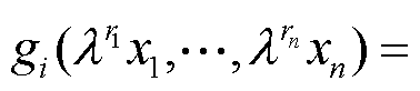
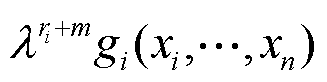 ,gi为g(x)中的第i个分量。则称系统g(x)是m次齐次的。
引理1[21]:若非线性系统g(x)渐进稳定,且系统的齐次度m<0,则该系统是全局有限时间稳定的。
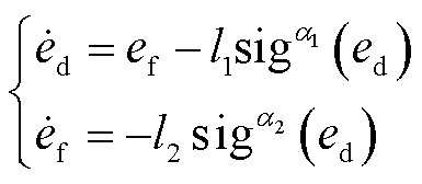
根据式(10)可得系统的扰动误差为:ed=xd1-zd1,ef =xd2-zd2。
对扰动误差求微分可得
 (25)
(25)
记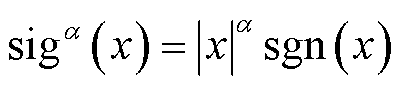 ,则式(25)可化简为
 (26)
(26)
根据文献[22]可取Lyapunvo函数 为
为
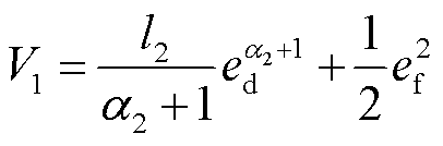 (27)
(27)
对式(27)求导数可得
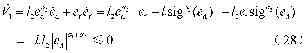
由于 ,则该系统是渐近稳定的。另外,根据定义1,式(25)关于权重(r1,r2)是α-1次齐次的,而在上述观测器设计部分中α<1,故α-1<0,即式(25)是负齐次性的。根据引理1可知本文观测器是有限时间稳定的。
引理2[23]:考虑非线性系统 ,
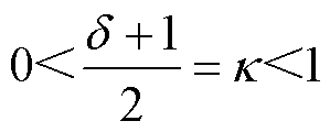
, ,若存在一个Lyapunvo函数V(x),在满足条件m>0、n>0、0<κ<1时,使得
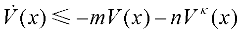 (29)
(29)
成立,则该系统是有限时间稳定的,并且收敛时间T满足
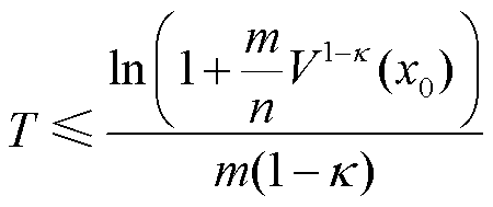 (30)
(30)
选择Lyapunvo函数V2为
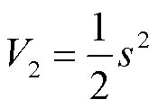 (31)
(31)
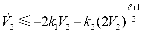
对式(31)求导数可得
 (32)
(32)
即有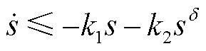 ,当从系统初始状态s0运动至s=1时,δ>1。对两边同乘以s-δ并求积分得此阶段收敛时间t1为
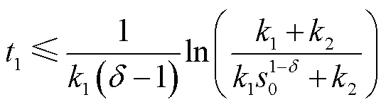 (33)
(33)
当从s=1到平衡点s=0时,有0<δ<1,联立式(31)、式(32),则可将式(32)表示为
 (34)
(34)
令式(34)中 ,
, ,
, ,则式(34)可进一步简化为
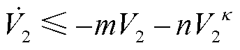 。
。
根据引理2可知,该阶段收敛时间t2=T,因此本文滑模反馈控制系统可在有限时间稳定且收敛时间t≤t1+t2。
为了验证本文设计的控制策略的可行性,在Simulink中搭建了两级式PCS的仿真电路,并且将PI控制和未改进的ADRC与本文控制进行对比,进而分析本文控制方法的优势。电路参数和控制器参数分别见表1、表2。
表1 电路模型参数
Tab.1 Circuit model parameters
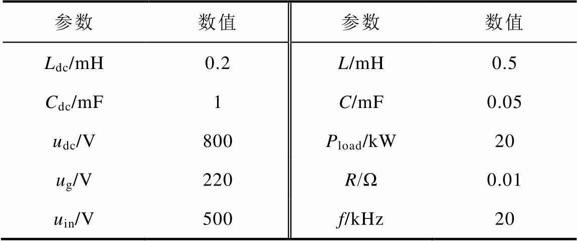
参数数值参数数值 Ldc/mH0.2L/mH0.5 Cdc/mF1C/mF0.05 udc/V800Pload/kW20 ug/V220R/Ω0.01 uin/V500f/kHz20
表2 控制器参数
Tab.2 Controller parameters
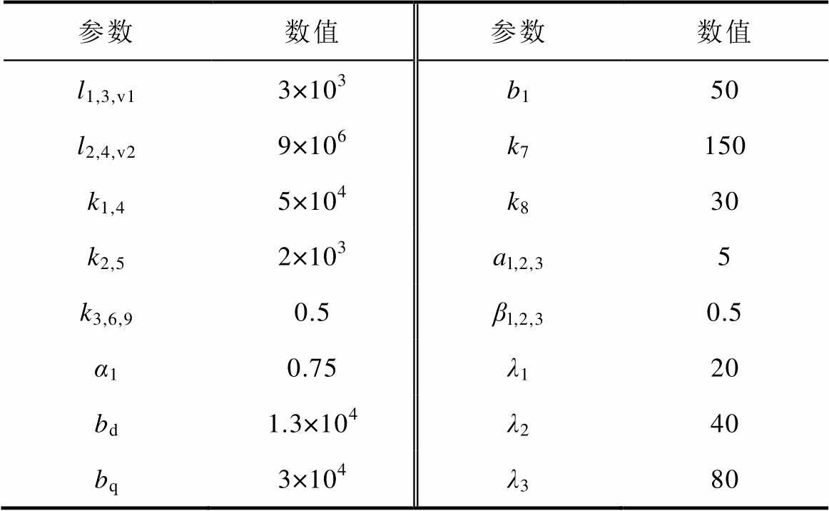
参数数值参数数值 l1,3,v13×103b150 l2,4,v29×106k7150 k1,45×104k830 k2,52×103al,2,35 k3,6,90.5βl,2,30.5 α10.75λ120 bd1.3×104λ240 bq3×104λ380
为了验证本文控制策略相比于传统控制策略的暂态优势,在仿真中设置了相应的有功功率暂态突变,得到不同控制策略下有功功率仿真对比结果如图4所示。
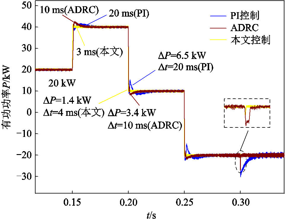
图4 不同控制策略下有功功率响应仿真对比
Fig.4 Simulation comparison of active power response under different control strategies
由图4可知,仿真中PCS部分有功功率设置了三次突变过程,即有功功率在0.15 s从20 kW跳变为40 kW、0.2 s从40 kW跳变至10 kW、0.25 s从10 kW跳变至-20 kW(“-”表示PCS吸收功率)。分析图4可知,PI控制和ADRC时功率跳变后产生了一定量的超调,并且经过了一段时间才恢复到稳态运行;而本文控制相比于其他两种控制产生的超调量更小,恢复至稳态的暂态时间更短。图4中虚线框出的部分是因无功功率在0.3 s时发生跳变而产生的耦合影响,可见本文控制耦合抑制效果更明显。
图5为不同控制策略下PCS无功功率响应,仿真中无功功率设置了1次跳变,在起始时刻到0.3 s间隔内无功功率一直保持为零,在0.3 s时无功功率跳变至20 kvar。分析图5可知,0.3 s之前的无功功率波动由耦合影响导致,本文控制的耦合抑制效果更明显;另外无功功率突变时本文控制的功率波动和纹波也小于其他两种控制。
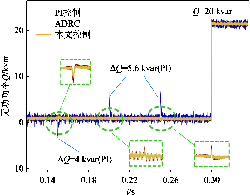
图5 不同控制策略下PCS无功功率响应仿真对比
Fig.5 Simulation comparison of PCS reactive power response under different control strategies
因前后两级变换器直接连接,当PCS输出的功率发生变化时,直流母线电压也会在对应功率跳变的时刻产生电压波动,其波形如图6所示。
分析图6可知,PCS输出有功功率在0.15 s时从20 kW跳变至40 kW,0.2 s时从40 kW跳变至10 kW。在此暂态时刻,PI控制策略下直流侧的电压超调分别达到25 V和40 V,恢复到电压给定值的暂态时间分别为13 ms和17 ms;同样的暂态过程下,ADRC超调分别为17 V和24 V,过渡时间分别为10 ms和13 ms;而在本文控制策略下,电压超调分别只有5 V和6 V,暂态时间也只有4 ms和5 ms。在0.25 s时PCS由输出10 kW变换为吸收20 kW有功功率,对于此过程造成的直流母线电压波动,本文控制同样具有更小的超调量和更短的过渡时间。在0.3s时无功功率从0跳变至20 kvar,由图6可知无功功率跳变对电压波动造成的影响相对有功功率更小,从仿真结果分析可知本文控制在快速性和抗扰动性方面的效果更优。
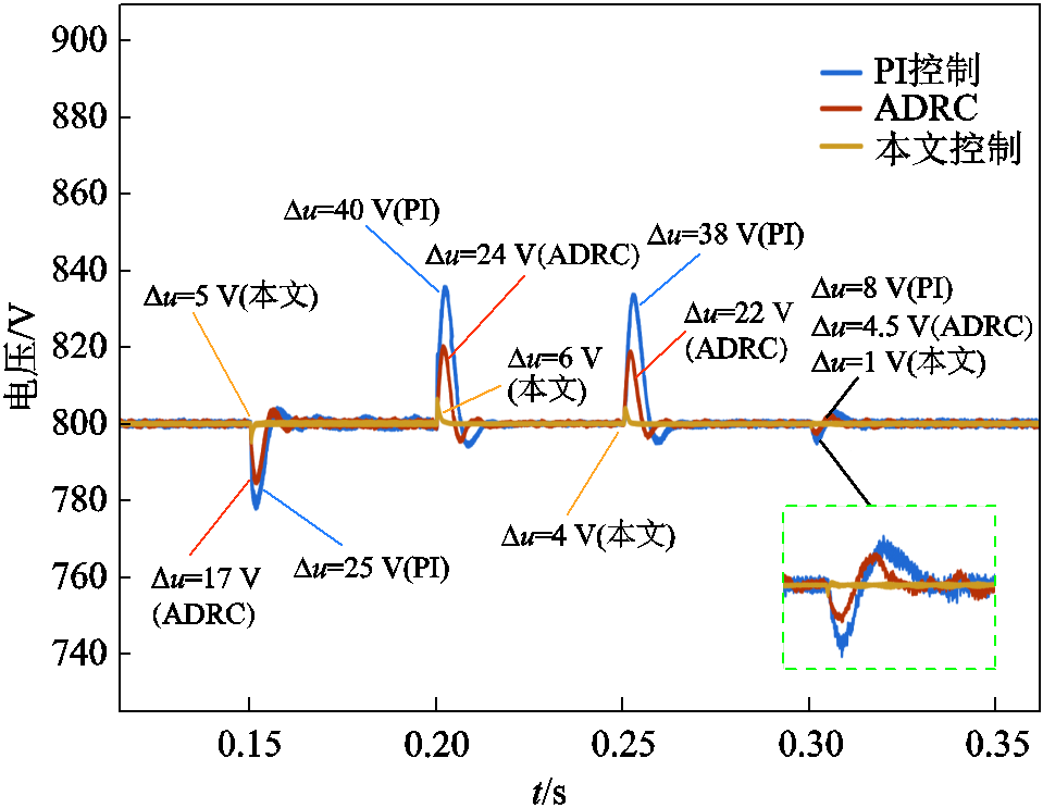
图6 不同控制策略下直流母线电压响应
Fig.6 DC bus voltage response under different control strategies
为验证本文控制对PCS输出电流电能质量的影响,在Simulink中对PCS输出有功功率在20 kW时的并网电流进行了2个稳态周期的傅里叶分析。结果如图7所示,三种控制下的谐波畸变率分别为4.52%、2.16%和1.63%。由此可知本文控制的谐波含量更少,因此本文控制下系统提供的电能质量更高。
硬件在环(Hardware-in-the-Loop, HIL)实验平台如图8所示,采样频率为20 kHz。首先在StarSin中搭建仿真电路,然后将电路经上位机载入MT6020和RCP1050中,再通过转接板将实验平台与示波器进行物理连接。将PI控制、ADRC和本文控制应用于实验中进行对比分析。
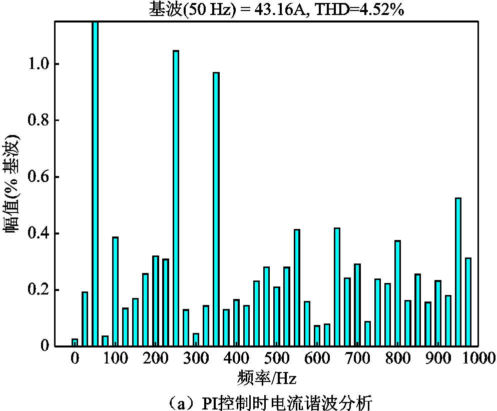
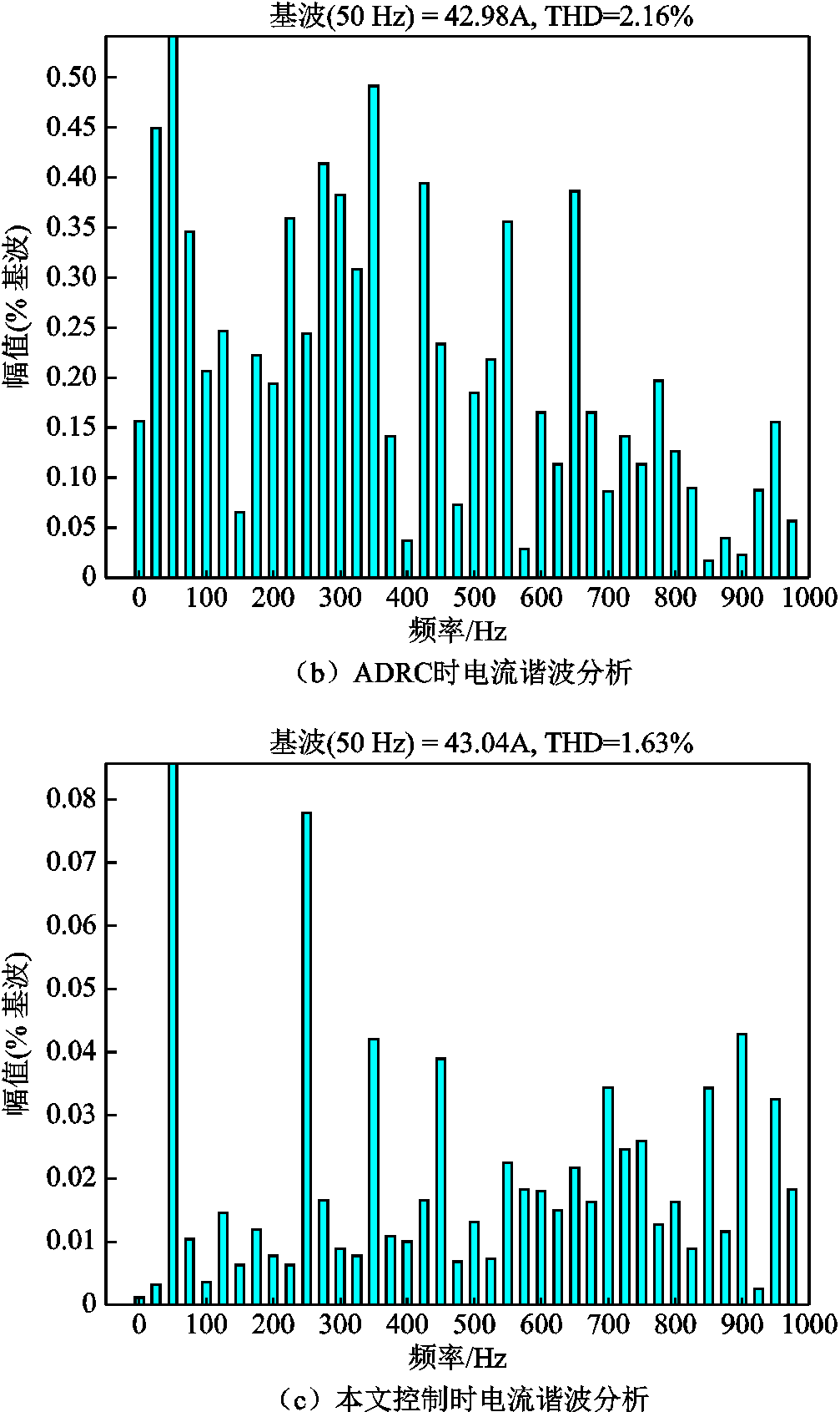
图7 不同控制下电流谐波分析
Fig.7 Harmonic analysis of current under different control strategies
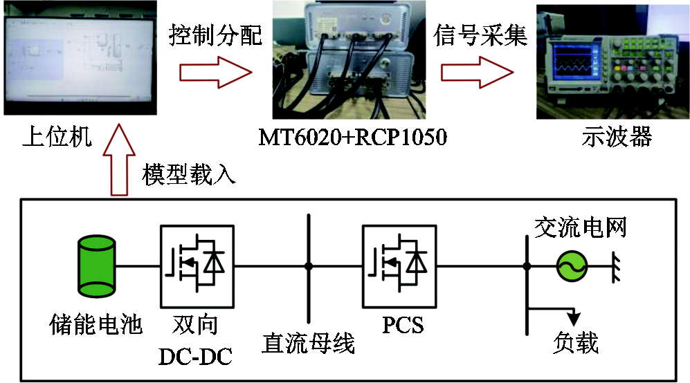
图8 硬件在环实验平台
Fig.8 Hardware-in-the-loop experiment platform
实验过程中PCS输出功率不便测量显示,根据式(3)可知输出功率与坐标变换后的dq轴电压电流具有直接关系,且d轴电压是恒定的,故可通过观察dq轴电流来反映输出功率的变换情况。不同控制下的有功功率暂态响应如图9所示。图9中id、iq分别为d、q轴电流,ib为PCS交流侧b相电流。由式(3)可得当PCS输出有功功率20 kW、无功功率为0时,id=43 A,iq=0。

图9 不同控制下的有功功率暂态响应
Fig.9 Active power transient response under different control strategies
当PCS输出有功功率从20 kW跳变到60 kW时,id从43 A跳变至129 A。由图9a可知,在PI控制策略下从跳变起始到恢复稳态的过渡时间为28 ms;从60 kW跳变至20 kW时的过渡时间为 32 ms。两次功率跳变均产生了一定的超调量,另外由于功率之间存在的耦合性使得在有功功率突变时也引起了无功功率的暂态变化,如图9a中红色虚线框出部分。由图9b可知,ADRC下的功率跳变过程时间比PI控制有所减少,并且耦合产生的影响也得到了抑制。由图9c可知,在本文控制策略下,两次功率跳变的过渡时间分别为8 ms和9 ms,且跳变期间过渡比较平滑没有产生超调,耦合影响也得到了更好的抑制。
有功功率方向切换时,不同控制下的暂态响应如图10所示。分析图10可知,当PCS输出功率从20 kW跳变至-20 kW,即PCS由输出功率变为吸收功率时,id从43 A跳变至-43 A。由图10a可知,PI控制下两次跳变的过渡时间分别为28 ms和27 ms。由图10b可知,ADRC下的过渡时间分别为20 ms和19 ms,收敛速度较PI控制有所提高。本文控制策略下功率方向切换时的过渡时间分别为11 ms和 12 ms,同时本文控制对耦合的效果也更优。

图10 有功功率方向切换时不同控制下的暂态响应
Fig.10 Transient response of active power direction switching under different control strategies
不同控制下的无功功率暂态响应如图11所示。图11中有功功率保持在20 kW,当无功功率从0跳变至30 kvar时,iq从0跳变至-64 A。在PI控制策略下从无功功率开始跳变经过了21 ms恢复稳定,同时暂态期间产生了一定的超调量且有功电流iq因两者之间的耦合受到了波动;ADRC下的过渡时间为17 ms,并且基本没有超调;本文控制策略下的暂态变化更加平滑,过渡时间只有9 ms,且id与iq之间的耦合影响也得到了抑制。
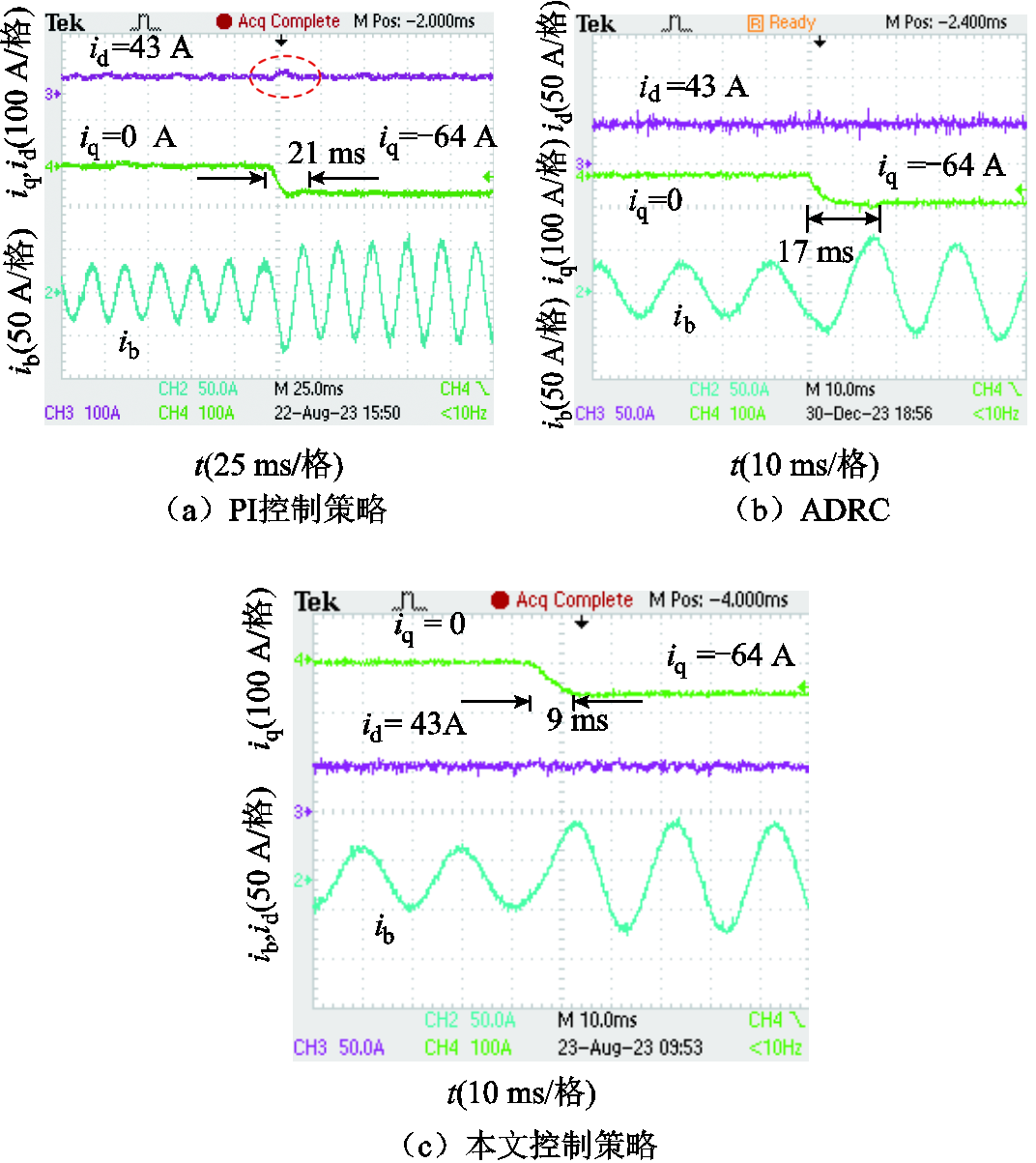
图11 不同控制下的无功功率暂态响应
Fig.11 Reactive power transient response of under different control strategies
实验设定直流母线电压在稳态时为800 V,输出功率突变时不同控制下的母线电压暂态响应如图12所示。图12a中,在PI控制策略下,当PCS输出功率从20 kW向60 kW突变时,直流母线电压超调量Δ为40 V,经过25 ms恢复至稳态;当输出功率从60 kW向20 kW突变时,电压波动产生的超调量Δ为38 V,过渡时间为23 ms。图12b中,两次跳变过程产生的超调量Δ分别为26 V和23 V,过渡时间分别为13 ms和14 ms。图12c中,在本文控制策略下两次功率跳变引起的电压超调量分别为10 V和9 V,两次暂态过程的过渡时间分别为6 ms和7 ms。在功率大小跳变的过程中,本文控制表现出的暂态性能更优。
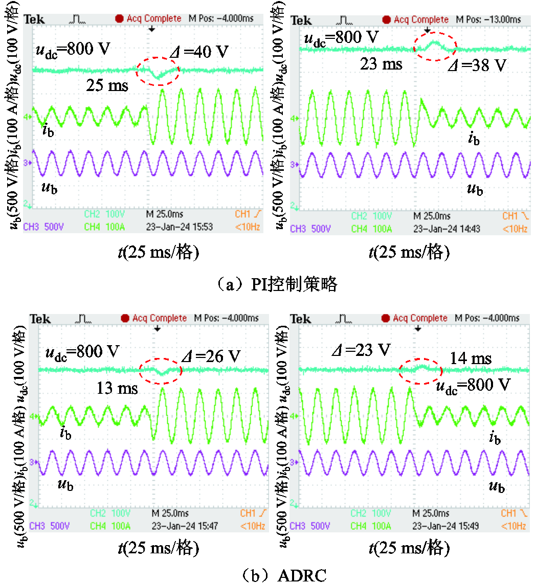
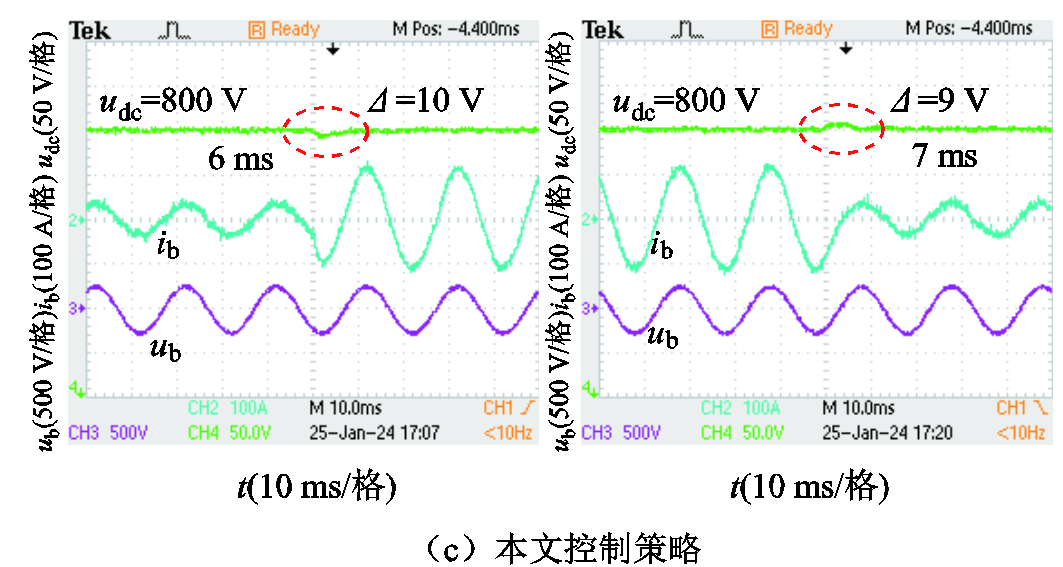
图12 输出功率突变时不同控制下的母线电压暂态响应
Fig.12 Transient response of bus voltage under different control strategies when output power changes
输出功率方向切换时不同控制下的母线电压暂态响应如图13所示。分析图13可知,当PCS从输出功率变换至吸收功率时,对于前级DC-DC模块即从放电状态转变为充电状态。图13a中在PI控制策略下,当输出功率由20 kW变化至-20 kW时,电压波动产生的超调为40 V,暂态时间为25 ms;当输出功率由-20 kW跳变至20 kW时,电压超调也为40 V,经过24 ms的过渡时间回到稳定状态。由图13b可知,在ADRC下两次跳变过程产生的超调量为24 V和21 V,分别经过13 ms和12 ms恢复稳态运行。由图13c可知,当功率的方向发生变化时,本文控制策略下电压的波动量更小,暂态时间更短。
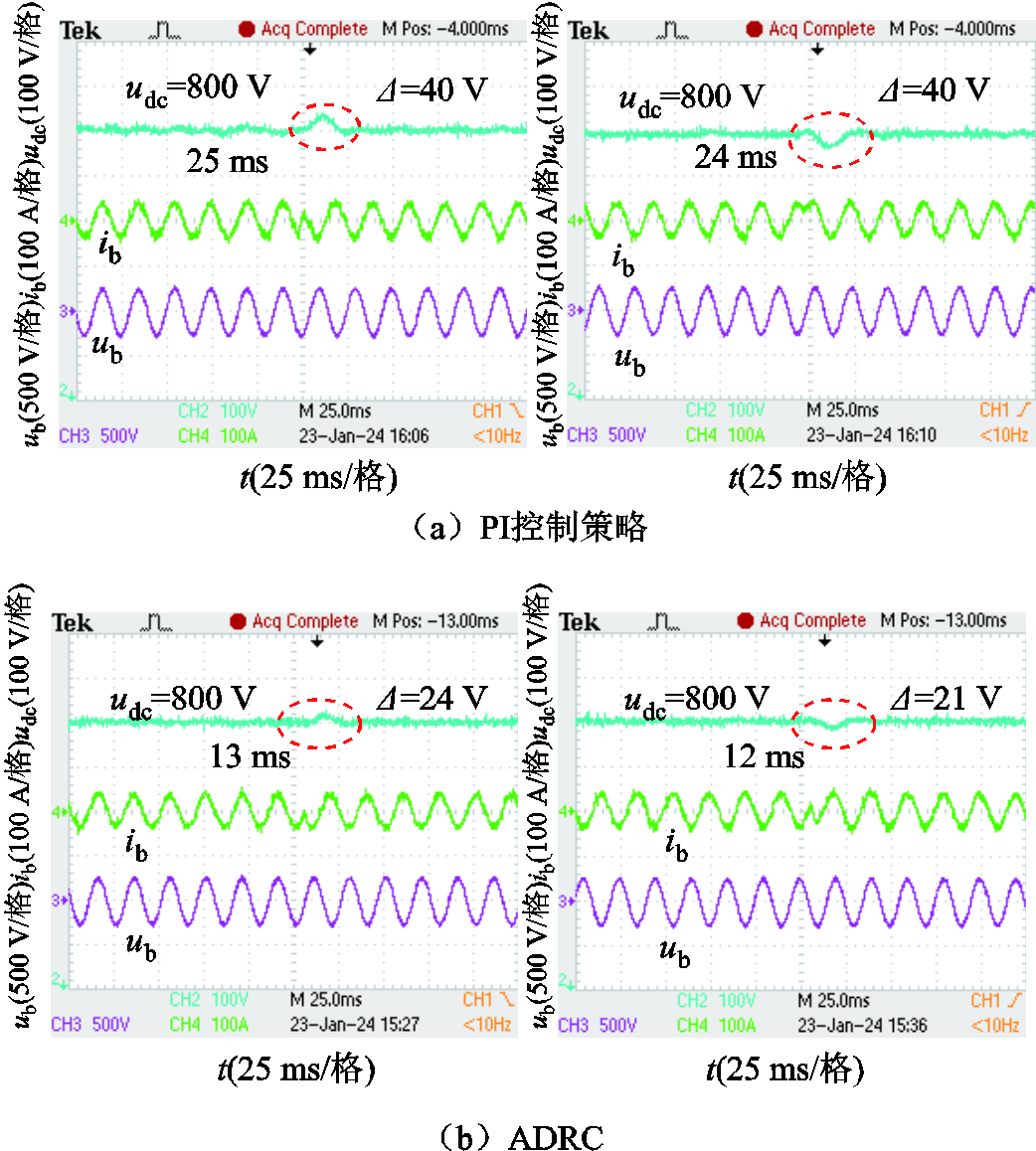
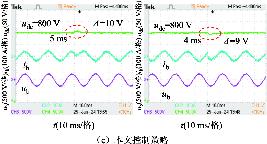
图13 输出功率方向切换时不同控制下的母线电压暂态响应
Fig.13 Transient response of bus voltage under different control strategies when output power direction switching
针对两级式储能变流器输出功率间存在的强耦合性,以及受到扰动后暂态性能差的问题,本文设计了一种基于有限时间观测器的滑模自抗扰控制策略。通过理论分析、仿真和实验对比,相比于PI控制和未改进的ADRC,得出如下结论:
1)利用ADRC理论将后级变流器的耦合部分归入集总扰动,通过有限时间观测器对集总扰动快速地观测补偿,实现了对耦合影响的抑制。
2)在PCS输出功率大小突变、功率方向切换时,本文设计的滑模自抗扰控制器减小了功率变化及直流母线电压波动的超调量,提高了响应速度,具有更好的暂态性能。另外,本文所提控制策略降低了并网电流谐波含量,使电能质量有所提高。
参考文献
[1] 张尧翔, 刘文颖, 庞清仑, 等. 基于主从博弈的跨境新型电力系统双边交易决策方法[J]. 电力系统自动化, 2023, 47(4): 19-26.
Zhang Yaoxiang, Liu Wenying, Pang Qinglun, et al. Bilateral transaction decision-making method for cross-border new power system based on stackelberg game[J]. Automation of Electric Power Systems, 2023, 47(4): 19-26.
[2] Zarrilli D, Giannitrapani A, Paoletti S, et al. Energy storage operation for voltage control in distribution networks: a receding horizon approach[J]. IEEE Transactions on Control Systems Technology, 2018, 26(2): 599-609.
[3] 陈光宇, 袁文辉, 徐晓春, 等. 基于残差图卷积深度网络的电网无功储备需求快速计算方法[J]. 电工技术学报, 2023, 38(17): 4683-4700.
Chen Guangyu, Yuan Wenhui, Xu Xiaochun, et al. Fast calculation method for grid reactive power reserve demand based on residual graph convolutional deep network[J]. Transactions of China Electrote-chnical Society, 2023, 38(17): 4683-4700.
[4] 王明磊. 基于自抗扰解耦控制的储能变流器稳定性研究[D]. 哈尔滨: 哈尔滨工业大学, 2020.
Wang Minglei. Stability study of battery energy storage power converter system based on LADRC-CD control[D]. Harbin: Harbin Institute of Technology, 2020.
[5] 王海鑫, 袁佳慧, 陈哲, 等. 智慧城市车-站-网一体化运行关键技术研究综述及展望[J]. 电工技术学报, 2022, 37(1): 112-132.
Wang Haixin, Yuan Jiahui, Chen Zhe, et al. Review and prospect of key techniques for vehicle-station-network integrated operation in smart city[J]. Transactions of China Electrotechnical Society, 2022, 37(1): 112-132.
[6] Weaver W W, Robinett R D, Parker G G, et al. Energy storage requirements of DC microgrids with high penetration renewables under droop control[J]. International Journal of Electrical Power & Energy Systems, 2015, 68: 203-209.
[7] Delfino F, Ferro G, Minciardi R, et al. Identification and optimal control of an electrical storage system for microgrids with renewables[J]. Sustainable Energy, Grids and Networks, 2019, 17: 100183.
[8] 龚春阳, 林嘉伟, 黄冬梅, 等. 储能系统双向Buck-Boost变换器控制策略研究[J]. 太阳能学报, 2023, 44(2): 229-238.
Gong Chunyang, Lin Jiawei, Huang Dongmei, et al. Research on control strategy of bidirectional Buck-Boost converter in energy storage system[J]. Acta Energiae Solaris Sinica, 2023, 44(2): 229-238.
[9] 林莉, 范米, 林雨露, 等. 基于不确定与扰动估计器的直流配电网电压鲁棒控制[J]. 电工技术学报, 2023, 38(17): 4657-4671.
Lin Li, Fan Mi, Lin Yulu, et al. Uncertainty and disturbance estimator-based control for voltage robust controller in DC distribution network[J]. Transactions of China Electrotechnical Society, 2023, 38(17): 4657-4671.
[10] 郭昕, 黄守道, 彭昱, 等. 基于改进型双幂次趋近律与全局快速终端滑模观测器的IPMSM调速系统滑模控制[J]. 电工技术学报, 2023, 38(1): 190-203.
Guo Xin, Huang Shoudao, Peng Yu, et al. Sliding mode control of IPMSM speed regulation system based on an improved double power reaching law and global fast terminal sliding mode observer[J]. Transactions of China Electrotechnical Society, 2023, 38(1): 190-203.
[11] 张宇涵, 杜贵平, 雷雁雄, 等. 直流微网混合储能系统控制策略现状及展望[J]. 电力系统保护与控制, 2021, 49(3): 177-187.
Zhang Yuhan, Du Guiping, Lei Yanxiong, et al. Current status and prospects of control strategy for a DC micro grid hybrid energy storage system[J]. Power System Protection and Control, 2021, 49(3): 177-187.
[12] 杨林, 曾江, 马文杰, 等. 基于改进二阶线性自抗扰技术的微网逆变器电压控制[J]. 电力系统自动化, 2019, 43(4): 146-153.
Yang Lin, Zeng Jiang, Ma Wenjie, et al. Voltage control of microgrid inverter based on improved second-order linear active disturbance rejection control[J]. Automation of Electric Power Systems, 2019, 43(4): 146-153.
[13] 于艳君, 崔明恺, 柴凤. 双绕组永磁同步电机滑模变结构控制[J]. 电工技术学报, 2022, 37(22): 5799-5807.
Yu Yanjun, Cui Mingkai, Chai Feng. Sliding mode variable structure control of a dual-winding permanent magnet synchronous motor[J]. Transactions of China Electrotechnical Society, 2022, 37(22): 5799-5807.
[14] 石波, 李待兴, 郭伟, 等. 小型压水堆稳压器多变量自抗扰解耦控制研究[J]. 核动力工程, 2021, 42(5): 143-148.
Shi Bo, Li Daixing, Guo Wei, et al. Study on multivariable decoupling control of small PWR pressurizer based on active disturbance rejection control[J]. Nuclear Power Engineering, 2021, 42(5): 143-148.
[15] Chen Cheng, Yang Huixin. Heading rate controller for unmanned helicopters based on modified ADRC[J]. Science China(Technological Sciences),2023, 66(5): 1255-1262.
[16] Yuan Liu, Xiu Chunbo, Ma Xin. Sliding mode control strategy for microgrid inverter systems[J]. Journal of Power Electronics, 2023, 23(5): 821-831.
[17] 赵希梅, 吴岑. 基于滑模自抗扰的PMLSM电流偏差解耦控制[J]. 光学精密工程, 2022, 30(4): 431-441.
Zhao Ximei, Wu Cen. Current deviation decoupling control based on sliding mode active disturbance rejection for PMLSM[J]. Optics and Precision Engineering, 2022, 30(4): 431-441.
[18] 陈鹏云, 张国兵, 李佳成, 等. 固定翼UAV路径跟踪的全局稳定积分滑模S面控制[J/OL]. 计算机工程与应用, 2024, 60(13): 353-360.
Chen Pengyun , Zhang Guobing , Li Jiacheng et al. Path tracking controller of fixed-wing UAVs based on globally stable integral sliding mode S-plane model[J]. Computer Engineering and Application, 2024, 60(13): 353-360..
[19] 张合新, 范金锁, 孟飞, 等. 一种新型滑模控制双幂次趋近律[J]. 控制与决策, 2013, 28(2): 289-293.
Zhang Hexin, Fan Jinsuo, Meng Fei, et al. A new double power reaching law for sliding mode control[J]. Control and Decision, 2013, 28(2): 289-293.
[20] Rosier L. Homogeneous Lyapunov function for homogeneous continuous vector field[J]. Systems & Control Letters, 1992, 19(6): 467-473.
[21] Bacciotti A, Rosier L. Liapunov Functions and Stability in Control Theory[M]. Berlin: Springer, 2005.
[22] Cao Pengfei, Gan Yahui, Dai Xianzhong. Finite-time disturbance observer for robotic manipulators[J]. Sensors, 2019, 19(8): 1943.
[23] Shen Yanjun, Huang Yuehua. Uniformly observable and globally Lipschitzian nonlinear systems admit global finite-time observers[J]. IEEE Transactions on Automatic Control, 2009, 54(11): 2621-2625.
Improved Sliding Mode Active Disturbance Rejection Control for Two-Stage Power Conversion System Based on Finite Time Observer
Abstract Under the traditional control strategy, the two-stage power conversion system(PCS) will produce a large overshoot and the response time from the jump to the steady-state operation is relatively long when the power jumps and the DC bus voltage fluctuates. At the same time, there is coupling effect between the active power and reactive power of the converter. To solve these transient problems, a sliding mode active disturbance rejection control strategy based on finite time convergence observer is designed in this paper.
The control strategy is applied to the power control of the rear DC-AC converter and the double-loop control of the DC-DC converter to improve the transient performance of the system. The basis of this control strategy is active disturbance rejection control (ADRC), which equates all uncertainties such as unknown disturbance and unmodeled part of the system to total disturbance, estimates the total disturbance by observer and compensates by feedforward channel, and then rapidly converges the feedback error to zero by sliding mode control. This control combines the advantages of ADRC independent of the precise mathematical model of the control object and fast convergence of the sliding mode control, which reduces the complexity of the controller and improves the transient response of the controller.
In order to facilitate the design of the controller during the design of the control strategy, the state equation of the two-stage power conversion system in the abc coordinate system is converted to the state equation in the dq coordinate system. According to the mathematical model of the dq coordinate system, it can be seen that there are coupling effects between the dq axis variables after the converter's coordinate transformation. In order to suppress the coupling phenomenon, the coupling part of the converter state equation is classified into total disturbance, and the equivalent total disturbance is estimated quickly and accurately by designing a finite time convergence observer, and the disturbance estimate is improved by feedforward compensation. Secondly, the linear feedback link in ADRC is replaced by a nonlinear sliding mode control with faster response and insensitive to parameters, which improves the error convergence speed and the disturbance immunity performance of the controller. In sliding mode feedback control, the integral sliding mode is used to reduce the steady-state error in the control process, and the sliding mode reaching law is composed of exponential reaching law and power reaching law, which ensures the fast reaching ability when the control orbit is far from the equilibrium point, and also has the ability to reduce chattering when the control orbit is near the equilibrium point. At the same time, in order to provide stable bus voltage on DC side, the proposed control is applied to double loop control of DC side voltage and current according to the state equation of DC-DC converter to improve the transient stability of DC bus voltage fluctuation. Then the stability and finite-time convergence of the proposed control strategy are proved according to Lyapunov stability theory, and the convergence time of the sliding mode feedback control law is calculated.
Finally, the circuit model of the two-stage power conversion system is built in Matlab/Simulink simulation software and hardware in the loop (HIL)experiment, and the proposed control is applied to carry out simulation and experimental verification, and the control is compared with PI control and unimproved ADRC. The transient performance of three different control strategies in terms of power change, coupling effect, harmonic content and DC bus voltage fluctuation is compared. The simulation and experimental results show that compared with the other two control methods, the proposed control can significantly suppress the coupling effect, reduce the harmonic content of grid-connected current, and improve the transient performance when the power changes and the DC bus voltage fluctuates.
Keywords:Two-stage power conversion system, finite-time observer, active disturbance rejection control, integral sliding mode, StarSim
中图分类号:TM46
DOI: 10.19595/j.cnki.1000-6753.tces.231469
陕西省自然科学研究项目资助(2023-JC-YB-442)。
收稿日期 2023-09-06
改稿日期 2024-04-09
黄红杰 男,1998年生,硕士研究生,研究方向为电力电子变换器及其控制技术。
E-mail:h252308@126.com
皇金锋 男,1978年生,博士,教授,硕士生导师,研究方向为电力电子变换器及其控制技术。
E-mail:jfhuang2000@163.com(通信作者)
(编辑 赫 蕾)