图1 中频真空电弧实验电路
Fig.1 Experiment circuit for intermediate frequency vacuum
摘要 为深入掌握航空变频(360~800 Hz)电力系统中真空电器电弧特性,该文围绕中频灭弧室弧后发生的边缘击穿现象,以双温磁流体动力学仿真结合实验的研究方法,得到了以下结论:中频真空电弧离子数密度的最大值为2.6×10¹⁹ m-3,离子温度的范围为0.30~0.91 eV,电子温度的范围为1.50~2.43 eV;电子与离子之间存在能量交换,电子温度的变化会引起离子温度的变化;最高离子温度出现在阳极触头边缘处,与实验发现的边缘击穿位置重合,证明了此处确实存在能量集中;中频真空电弧是超声速流体,速度在边界处减慢,根据动能热能互换原理,中频真空电弧的质量流运动规律是边缘击穿的本质原因。
关键词:航空变频电源 中频真空电弧 弧后击穿 边缘击穿 双温磁流体动力学模型
2022年末以来,C919飞机已经进行了大量地面和试飞实验,载客运营指日可待。C919飞机是典型的多电飞机,机上配备了航空变频(中频360~800 Hz)交流电力系统,这也是大型飞机供电技术最新的发展方向。在多电飞机核心部件国产化进程中,小体积航空电器开断中频、大电流电弧是目前的技术瓶颈[1-5]。
应用真空开关有望解决中频灭弧难题,国内外诸多学者也对此展开了研究。文献[6]认为中频条件下,真空电弧的阳极斑点现象不明显。文献[7-8]认为中频真空电弧呈过渡态及扩散态,等离子体参数为:电子温度为0.5~3 eV,电子密度为1020~1021 m-3。文献[9]认为在中频360~800 Hz范围内,真空开关完全满足航空电源的短路保护需求,并利用多物理场耦合仿真解释了大电流双柱电弧在磁场作用下形成扩散态电弧的过程。文献[10]提出一种正弦曲面触头,实验表明该结构可以降低中频真空电弧燃弧能量及触头烧蚀程度,研究发现弧后击穿过程直接影响中频真空电弧的灭弧能力。文献[11]发现真空断路器开断1 000 Hz以下中频电弧时,弧后击穿电压随频率增加而降低。文献[12]认为在未发生阳极斑点的情况下,电弧加热触头使其释放出的金属液滴及其蒸发出的金属蒸气,会降低灭弧室内的介质恢复强度,是导致中频弧后击穿的最重要因素。
目前研究中频真空电弧的主要手段有实验观察和建模仿真,其中建模仿真是揭示电弧放电过程物理本质的有效方法。主流的等离子体建模方法有时变方程法[13]、粒子碰撞法[14]、磁流体动力学法(Magneto Hydro-Dynamic, MHD)[15]及混合模拟法[16]等。对于工频真空电弧,国内外已有大量文献对超声速/亚声速电弧建模理论、双温MHD模型、等离子体作用阳极烧蚀等问题进行了探讨[17-20];而关于中频真空电弧的仿真,现有的研究并不多见。文献[21]计算了中频真空电弧的内部压力,分析了等离子体射流形成的原因。文献[22]计算了中频纵向磁场,分析了线圈匝数、开槽数等触头结构参数对磁滞效应的影响。文献[23]计算了中频真空电弧弧后的金属蒸气密度,预测了发生击穿的临界电压。上述中频真空的仿真均未涉及MHD方程,研究深度尚浅。而即使在中频条件下,等离子体的平均碰撞时间也远小于电流变化时间和穿越开距时间,电子和离子也服从麦克斯韦分布,因此工频时的MHD方法可以作为研究中频真空电弧的重要参考。
根据课题组之前的实验结果,中频真空电弧弧后击穿总是首先发生在触头边缘处,触头边缘处的电场强度集中、场致发射概率高是一方面原因[24],但电弧能量如何影响边缘击穿的原理尚不明确。本文将基于真空电弧的双温磁流体模型,通过计算电弧温度和压力等物理量,分析中频真空电弧边缘击穿现象及机理。
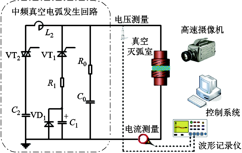
为方便获取电弧图像,本文在去除屏蔽罩的真空灭弧室内进行短路实验,实验开距为3 mm,触头直径为41 mm和20 mm两种规格,灭弧室内的气体压力为5×10⁻⁴ Pa。形成中频真空电弧的短路电流由储能电容和电感振荡产生,频率360~800 Hz可调,最大峰值为20 kA。中频真空电弧实验电路如图1所示。
图1 中频真空电弧实验电路
Fig.1 Experiment circuit for intermediate frequency vacuum
中频真空电弧发生回路由振荡和引弧两条支路组成。为最大限度地去除分闸时机械振动和机构分散性给电弧带来的影响,在真空灭弧室合闸状态下,实验先投入引弧支路,待电流稳定,真空灭弧室分闸,再投入振荡支路,形成中频电弧。引弧支路由晶闸管VT1、电阻R1、直流电容C1、二极管VD1组成,其中VT1作为控制开关,VD1作为电容C1的反向保护,经R1限流的引弧电流约为直流200 A;振荡支路由晶闸管VT2、交流电容C2和电感L2组成,其中VT2作为控制开关,预先充电的C2和L2发生振荡。另外,为了模拟开断后的瞬态过程,由电容C0和电阻R0组成的调频回路可在电流过零后形成约150 kHz的瞬态恢复电压。
实验中真空灭弧室断口最高恢复电压约为1 000 V,电压探头的最大量程为2 000 V;实验中电弧电流最大值约为20 kA,电流传感器的最大量程为30 kA,响应频率为0.1 Hz~30 MHz;高速摄像机的曝光时间为1/35 087 s。
中频真空电弧的物理模型如图2所示,阴极斑点发射电子,弧柱充满了离子和电子,离子和电子运动合成了电弧电流。
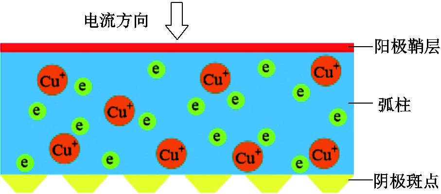
图2 中频真空电弧的物理模型
Fig.2 Physical model of intermediate frequency vacuum arc
本文后续建立的中频真空电弧双温MHD模型基于以下假设条件:①弧柱区域完全电离,仅含离子和电子,不考虑中性粒子作用;②德拜长度的数量级为10-8 m,电子平均自由程的数量级为10-4 m,触头开距为3 mm,求解区域满足准中性条件,可用流体理论等效中频真空电弧;③电子、离子平均碰撞时间的数量级分别为10-11 s、10-9 s,电子、离子穿越弧隙时间的数量级分别为10-7 s、10-6 s,中频电流半波燃弧时间为0.62~1.38 ms,求解过程可认为是稳态问题;④电子是理想气体,忽略电子的质量流、惯性分量和黏性分量;⑤中频真空电弧等离子体未处于局部热力学平衡状态,需要将离子温度和电子温度分别计算;⑥将弧柱区作为磁流体区域进行计算,将阳极鞘层和阴极斑点作为仿真边界。
根据前述的中频真空电弧假设条件,本文建立如下电弧数学模型。
1)质量方程
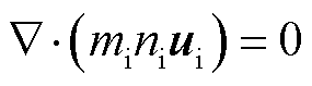 (1)
(1)
式中,mi为离子质量;ni为离子数密度;ui为离子运动速度。
2)动量方程
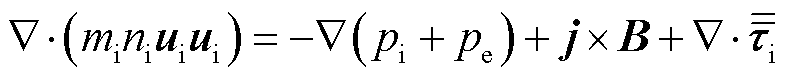 (2)
(2)
式中,pi和pe分别为离子和电子压力;j为电流密度;B为磁感应强度; 为离子的黏性应力张量。
3)离子能量方程
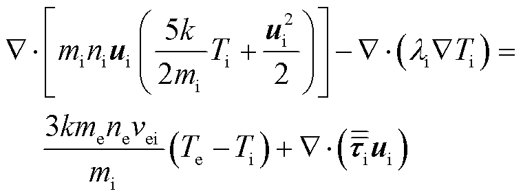 (3)
(3)
式中,k为玻耳兹曼常数;Ti和Te分别为离子和电子温度;li为离子热导率;me为单个电子质量;ne为电子数密度;vei为电子和离子的碰撞频率。
4)电子能量方程
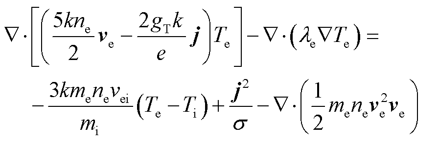 (4)
(4)
式中,gT为参数,完全电离的等离子体为1.5[25-26];ve为电子运动速度;e为电子电荷量;le为电子热导率;s为电导率。
5)电势方程
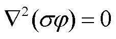 (5)
(5)
式中,φ为电势。
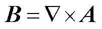
6)在库伦规范的约束下,矢量磁位A和φ在描述电磁场时具有唯一性。为提高求解磁场的收敛性,本文利用矢量磁位求解。
 (6)
(6)
7)矢量磁位方程
 (7)
(7)
式中, 为真空磁导率。
8)电中性方程
 (8)
(8)
式中,Zi为离子平均带电荷数,本文取1.85[25-26]。
9)电子速度方程
 (9)
(9)
2.3.1 阴极(压力入口)边界条件
根据文献[25],阴极边界的离子温度Ti = 0.3 eV = 3 482 K,电子温度Te = 1.5 eV = 17 408 K,电流和离子分布均匀。阴极边界的电流密度jc为
 (10)
(10)
式中,I为电弧电流,本文仿真的电弧电流为500 A;R为阴极半径。根据文献[19],真空电弧的状态受电弧电流的影响很大,在电流较小时,离子处于超声速流动状态,即本文仿真的中频真空电弧是超声速流体。文献[27]研究发现对于超声速电弧,大多数情况下其流动处于湍流状态。阴极边界的离子密度nic为
 (11)
(11)
式中,g为阴极触头的电极侵蚀率,与触头材料有关,根据Kimblin的实验结果,CuCr50触头电极的侵蚀率取115 μg/C[28];uiz为离子速度的轴向分量。
阴极边界的压力pic为
 (12)
(12)
2.3.2 阳极(压力出口)边界条件
根据以往的中频真空电弧实验,小开距情况下阳极斑点并不显著,据此本文假设阳极处于不活跃状态,只作为离子、电子的出口,不影响电弧的流动状态,且忽略阳极鞘层电压的影响,仿真中阳极被看作是等势面。
根据流体理论,当流体处于超声速流动状态时,出口的边界条件不影响内部流体的流动,边界值可根据内部流体的流动外推得到,因此温度等物理量不需要指定边界值。
2.3.3 初始条件
本文建立的中频真空电弧模型为稳态求解问题,虽然初始值对结果没有影响,但为了加快收敛速度及提高收敛稳定性,仍需要对计算区域给定初始值:将中频真空电弧弧柱区内的速度、压力、离子温度、电子温度等物理量的初始值均设为阴极(压力入口)边界值。
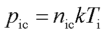
根据前文的介绍,中频真空电弧的双温MHD模型中包括质量、动量、能量、电磁场等方程及其之间的耦合,本文选用Fluent软件进行求解。关于流体场,流体类型为湍流模型,Fluent可通过内构方程对离子密度、离子速度、离子温度等物理量直接求解;矢量磁位、电势、电子温度等物理量及其他显式变量,可通过C语言开发自定义函数(User Defined Function, UDF)求解。控制方程的离散方法是迎风差分。
中频真空电弧双温MHD模型的求解过程如图3所示。每次迭代过程中,先利用DEFINE_ADJUST函数对显式变量和物性参数等进行更新;其次求解质量、动量、离子能量方程;再次求解电子能量方程和电磁场方程;若所有的方程均满足收敛条件,计算结束,否则开始新的迭代过程。
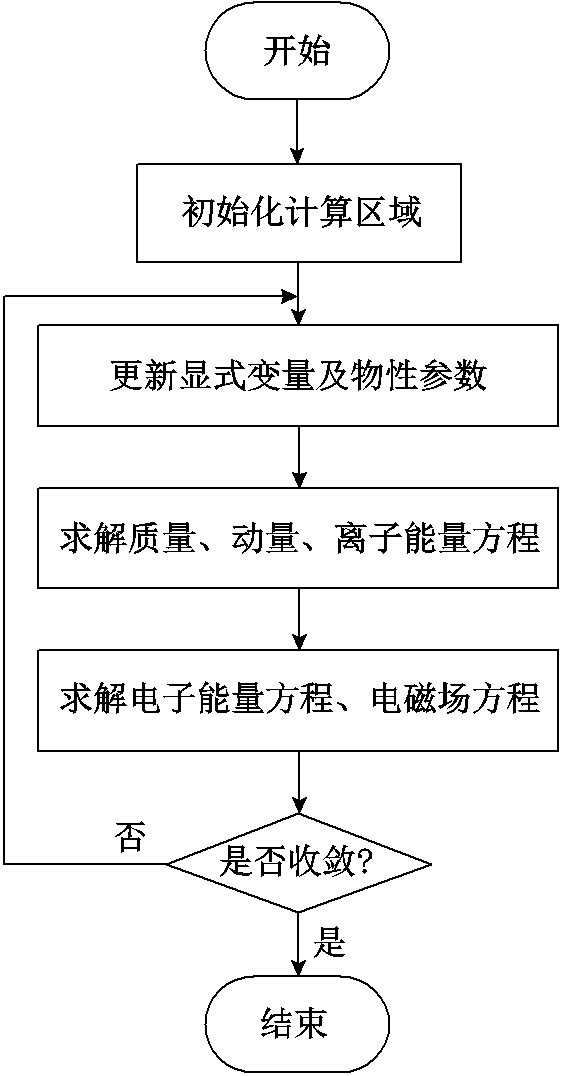
图3 中频真空电弧双温MHD模型的求解过程
Fig.3 The solution process for two temperature MHD model of intermediate frequency vacuum arc
图4所示为中频真空电弧燃弧及弧后击穿的电压和电流波形。如图4a所示,当首半波电流峰值Ipeak达到20 kA时,燃弧期间电压出现明显尖峰,峰值为83.3 V,弧后击穿阶段出现了明显的电弧电压噪声。当首半波电流峰值Ipeak为22.4 kA时,如图4b所示,燃弧期间电压尖峰值为74.7 V。
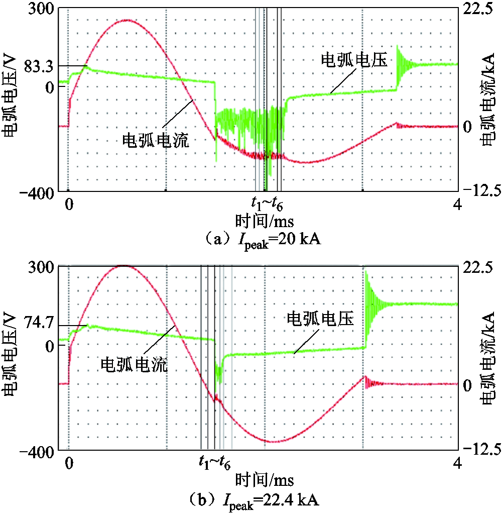
图4 中频真空电弧燃弧及弧后击穿的电压和电流波形
Fig.4 Voltage and current waveforms of intermediate frequency vacuum arc and post-arc breakdown
图5所示为中频真空电弧在41 mm触头中的弧后击穿过程,两组实验的最大开断电流(即首半波流峰值)Ipeak分别为20.0 kA和22.4 kA,图中i1~i6分别为图4中时间t1~t6所对应的电流。两组弧后击穿的相似之处是当正向电流过零后,首先在阴阳极触头的边缘发生局部弧后击穿,即形成对称的击穿点,然后击穿点面积逐渐扩大,形成反向放电通道,电弧进入电流负半波燃弧状态。

图5 中频真空电弧在41 mm触头中的弧后击穿过程
Fig.5 Breakdown of intermediate frequency vacuum arc in 41 mm contact
类似的弧后击穿现象在20 mm触头中也有发生。中频灭弧室的触头边缘击穿现象,其本质是电弧寻找到了最易释放能量的位置,反映出弧后介质的绝缘强度存在局部薄弱点。将实验后的中频真空灭弧室拆解,可以观察到触头边缘有严重的烧蚀,如图6所示。推测弧后击穿点的温度相比其他位置较高,可通过仿真来验证这一猜想。

图6 实验后的中频真空灭弧室触头烧蚀情况
Fig.6 Contacts of the intermediate frequency vacuum chamber after experiment
图7所示是中频真空电弧离子数密度ni的分布情况。从图7中可以看出,在小电流情况下,真空电弧呈扩散状,离子数密度从电弧中心到向边界逐渐减小,中心密度达到2.6×10¹⁹ m-3。离子的运动是磁箍缩力和压力梯度的合力作用结果。一方面,电弧电流较小时,由轴向电流密度与电弧感应磁场所产生的向中心的Bennet箍缩力较小[20];另一方面,根据实验结果,中频真空电弧呈扩散态,扩散的驱动力是压力梯度。也正因为电弧沿径向扩散,离子数密度从中心到边界逐渐减小。
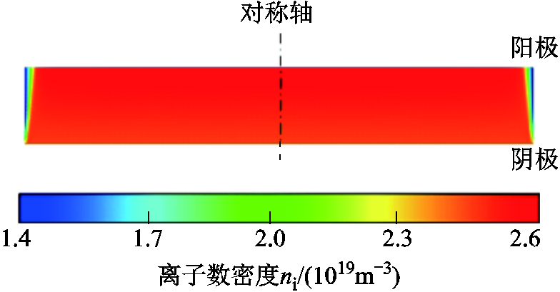
图7 中频真空电弧的离子数密度分布
Fig.7 Distribution of ion density of intermediate frequency vacuum arc
图8所示是中频真空电弧离子温度Ti和电子温度Te的分布情况。由于物理模型是轴对称结构,对称轴两侧分别表达两种温度。从图8中可以看出,从阴极到阳极,离子温度和电子温度总体上均呈现增加的趋势。离子温度从阴极区域的约0.30 eV增大到阳极区域的约0.91 eV,最高温度出现在阳极触头边缘处,与实验发现的边缘击穿位置重合,说明此处确实存在电弧能量集中,弧后大概率成为绝缘强度的薄弱点。电子温度从阴极区域的约1.50 eV增大到阳极区域的约2.43 eV,离子温度总是小于电子温度。根据电子能量方程,即式(4),电子温度增加的原因是焦耳热;同时,根据离子能量方程,即式(3),电子与离子之间存在能量交换,因此电子温度的变化会引起离子温度的变化。
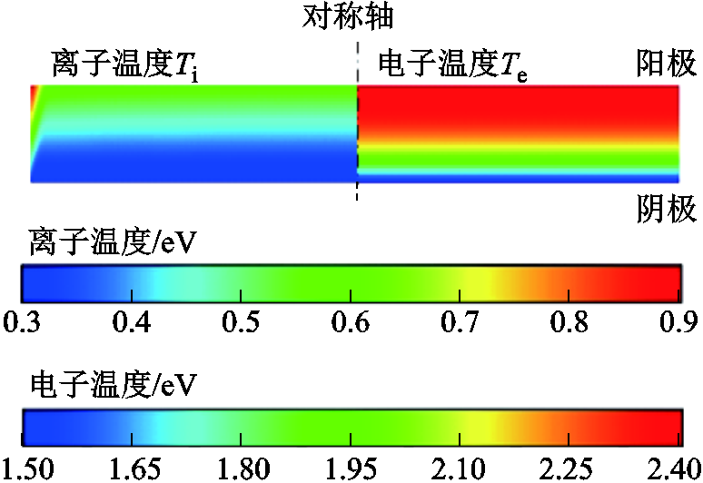
图8 中频真空电弧的离子和电子温度分布
Fig.8 Distribution of ion and electron temperatures of intermediate frequency vacuum arc
图9所示是中频真空电弧离子速度ui的分布情况。由于中频真空电弧的质量流是离子流,所以离子速度可以认为是等离子体速度。从图9中可以看出,中频真空电弧等离子体以轴向运动为主,弧柱区内速度变化并不大,最大值约为1 020 m/s,速度在边界处速度减慢。根据流体理论,热能与动能可以互相转化。由于中频真空电弧处于超声速流动状态,所以在离子速度变慢的区域,离子温度会显著增大。该结论与图8中的温度分布相一致,这也从中频真空电弧运动角度解释了触头边缘处热能较高的原因。
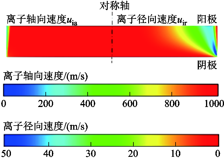
图9 中频真空电弧的离子速度分布
Fig.9 Distribution of ion velocity of intermediate frequency vacuum arc
本文通过中频真空电弧实验,建立了中频真空电弧的双温MHD仿真模型,以电弧理论联系实验现象的研究方法,得到了以下结论:
1)根据实验发现了中频灭弧室的边缘击穿现象,在中频真空灭弧室触头边缘处可见严重烧蚀,该现象反映出弧后介质的绝缘强度存在局部薄弱点。
2)根据双温MHD模型仿真结果,中频真空电弧离子数密度的最大值为2.6×10¹⁹ m-3,离子温度的范围为0.30~0.91 eV,电子温度的范围为1.50~2.43 eV。上述数据与其他学者得到的真空电弧微观参数的数量级一致,说明本文模型的计算结果具有正确性。
3)根据双温MHD模型仿真结果,电子温度增加的原因是焦耳热,由于电子与离子之间存在能量交换,电子温度的变化会引起离子温度的变化。最高离子温度出现在阳极触头边缘处,与实验发现的边缘击穿位置重合,说明此处确实存在能量集中。
4)根据双温MHD模型仿真结果,中频真空电弧处于超声速流动状态,弧柱区内速度变化较小,速度在边界处速度减慢。根据流体能量转换理论,低速区域热能高,说明中频真空电弧等离子体的质量流运动规律是边缘击穿的本质原因。
参考文献
[1] 宋清超, 陈家伟, 蔡坤城, 等. 多电飞机用燃料电池-蓄电池-超级电容混合供电系统的高可靠动态功率分配技术[J]. 电工技术学报, 2022, 37(2): 445-458. Song Qingchao, Chen Jiawei, Cai Kuncheng, et al. A highly reliable power allocation technology for the fuel cell-battery-supercapacitor hybrid power supply system of a more electric aircraft[J]. Transactions of China Electrotechnical Society, 2022, 37(2): 445-458.
[2] 蒋原, 李擎, 苗磊, 等. 多电飞机断路器电弧机理及灭弧技术研究综述[J]. 工程科学学报, 2023, 45(4): 611-620. Jiang Yuan, Li Qing, Miao Lei, et al. Overview of the arc mechanism and extinguishing in the circuit breaker of a more-electric aircraft[J]. Chinese Journal of Engineering, 2023, 45(4): 611-620.
[3] 纽春萍, 崔艺龄, 李忠翔, 等. 航空接触器散热特性分析及耦合迭代热分析方法[J]. 高电压技术, 2021, 47(2): 487-494. Niu Chunping, Cui Yiling, Li Zhongxiang, et al. Thermal dissipation characteristics analysis and coupling iterative thermal analysis method of aviation contactor[J]. High Voltage Engineering, 2021, 47(2): 487-494.
[4] 江军, 李治, 张本栋, 等. 低气压下航空线缆的局部放电特性[J]. 电工技术学报, 2022, 37(21): 5578-5586, 5626. Jiang Jun, Li Zhi, Zhang Bendong, et al. Partial discharge characteristics of aeronautical cables at low pressure[J]. Transactions of China Electrotechnical Society, 2022, 37(21): 5578-5586, 5626.
[5] 巩泉役, 彭克, 陈羽, 等. 基于电弧随机性和卷积网络的交流串联电弧故障识别方法[J]. 电力系统自动化, 2022, 46(24): 162-169. Gong Quanyi, Peng Ke, Chen Yu, et al. Identification method of AC series arc fault based on randomness of arc and convolutional network[J]. Automation of Electric Power Systems, 2022, 46(24): 162-169.
[6] 蒋原, 武建文. 纵向磁场中触头材料和直径对中频真空电弧特性的影响[J]. 中国电机工程学报, 2015, 35(20): 5367-5374. Jiang Yuan, Wu Jianwen. Effects of contact materials and diameters on characteristics of intermediate-frequency vacuum arc in axial magnetic field[J]. Proceedings of the CSEE, 2015, 35(20): 5367-5374.
[7] Wang Jing, Wu Jianwen, Zhu Liying. Properties of intermediate-frequency vacuum arc under axial magnetic field[J]. IEEE Transactions on Plasma Science, 2009, 37(8): 1477-1483.
[8] Wang Jing, Wu Jianwen, Zhu Liying. Arc behavior of intermediate-frequency vacuum arc on axial magnetic field contacts[J]. IEEE Transactions on Plasma Science, 2011, 39(6): 1336-1343.
[9] 蒋原, 武建文, 李擎, 等. 平板触头小开距中频真空电弧特性研究[J]. 中国电机工程学报, 2023, 43(16): 6517-6525. Jiang Yuan, Wu Jianwen, Li Qing, et al. Characteristics of intermediate frequency vacuum arc in butt contact with short gap[J]. Proceedings of the CSEE, 2023, 43(16): 6517-6525.
[10] Tong Ziang, Wu Jianwen, Li Kui, et al. A plasma diagnosis method for a vacuum arc under curved contact[J]. IEEE Transactions on Plasma Science, 2022, 50(9): 2700-2708.
[11] Qin Taotao, Dong Enyuan, Liu Guixin, et al. Recovery of dielectric strength after DC interruption in vacuum[J]. IEEE Transactions on Dielectrics and Electrical Insulation, 2016, 23(1): 29-34.
[12] 蒋原, 刘雨坤, 李擎, 等. 中频供电系统真空电弧开断过程与液滴喷射分析[J]. 中国电机工程学报, 2020, 40(2): 684-692. Jiang Yuan, Liu Yukun, Li Qing, et al. Interruption and droplets emission in intermediate-frequency vacuum arc of aviation power supply system[J]. Proceedings of the CSEE, 2020, 40(2): 684-692.
[13] 舒立春, 王鹏浩, 徐宁, 等. 基于改进时变电弧方程的直流覆冰闪络动态电路模型研究[J]. 电工技术学报, 2018, 33(19): 4603-4610. Shu Lichun, Wang Penghao, Xu Ning, et al. Study on dynamic circuit model of DC icing flashover based on improved time-varying arc equation[J]. Transactions of China Electrotechnical Society, 2018, 33(19): 4603-4610.
[14] Wang Dan, Wang Lijun, Wang Zhiwei, et al. 2-D particle simulation on the influence of transverse magnetic field on the plasma decay in postarc stage of vacuum circuit breakers[J]. IEEE Transactions on Plasma Science, 2020, 48(11): 3975-3981.
[15] 郝莎, 徐建源, 林莘. 隔离开关电弧流体数学模型研究与应用[J]. 电工技术学报, 2021, 36(13): 2710-2718. Hao Sha, Xu Jianyuan, Lin Xin. Study on the application of fluid arc model in disconnector[J]. Transactions of China Electrotechnical Society, 2021, 36(13): 2710-2718.
[16] 王振兴, 曹志远, 李瑞, 等. 纵磁作用下真空电弧单阴极斑点等离子体射流三维混合模拟[J]. 物理学报, 2021, 70(5): 055201. Wang Zhenxing, Cao Zhiyuan, Li Rui, et al. Three-dimensional hybrid simulation of single cathode spot vacuum arc plasma jet under axial magnetic field[J]. Acta Physica Sinica, 2021, 70(5): 055201.
[17] Schade E, Leonidovich Shmelev D. Numerical simulation of high-current vacuum arcs with an external axial magnetic field[J]. IEEE Transactions on Plasma Science, 2003, 31(5): 890-901.
[18] 赵杰, 游颖敏, 舒亮, 等. 磁流体仿真与正交试验融合设计的灭弧室性能优化方法[J]. 电工技术学报, 2022, 37(20): 5347-5358. Zhao Jie, You Yingmin, Shu Liang, et al. The performance optimization of arc extinguishing chamber based on the integration analysis magnetic fluid simulation and orthogonal test[J]. Transactions ofChina Electrotechnical Society, 2022, 37(20): 5347-5358.
[19] Wang Lijun, Huang Xiaolong, Zhang Xiao, et al. Modeling and simulation of high-current vacuum arc considering the micro process of anode vapor[J]. Journal of Physics D: Applied Physics, 2017, 50(9): 095203.
[20] Ma Hui, Tian Yunbo, Geng Yingsan, et al. Anode erosion pattern caused by blowing effect in constricted vacuum arcs subjected to axial magnetic field[J]. IEEE Transactions on Plasma Science, 2015, 43(8): 2329-2334.
[21] Jiang Yuan, Wu Jianwen, Ma Suliang, et al. Appearance of vacuum arcs in axial magnetic field and butt contacts at intermediate frequencies[J]. IEEE Transactions on Plasma Science, 2019, 47(2): 1405-1412.
[22] 蒋原, 李擎, 夏丽娜, 等. 中频条件下真空灭弧室的纵向磁场仿真(英文)[J]. 电工技术学报, 2021, 36(11): 2424-2432. Jiang Yuan, Li Qing, Xia Lina, et al. Simulation of axial magnetic field in vacuum arc interrupters at intermediate frequency[J]. Transactions of China Electrotechnical Society, 2021, 36(11): 2424-2432.
[23] Jiang Yuan, Wu Jianwen, Li Qing, et al. Influence of metal vapor on post-arc breakdown for intermediate frequency vacuum arc[J]. Vacuum, 2021, 193: 110551.
[24] 蒋原, 李擎, 崔家瑞, 等. 纵向磁场下中频真空电弧的重燃现象分析[J]. 电工技术学报, 2020, 35(18): 3860-3868. Jiang Yuan, Li Qing, Cui Jiarui, et al. Re-ignition of intermediate frequency vacuum arc at axial magnetic field[J]. Transactions of China Electrotechnical Society, 2020, 35(18): 3860-3868.
[25] Kutzner J, Miller H C. Integrated ion flux emitted from the cathode spot region of a diffuse vacuum arc[J]. Journal of Physics D: Applied Physics, 1992, 25(4): 686-693.
[26] Miller H C, Kutzner J. Ion flux from the cathode region of a vacuum arc[J]. Contributions to Plasma Physics, 1991, 31(3): 261-277.
[27] 向川. 小间隙真空电弧的数值仿真与实验研究[D]. 大连: 大连理工大学, 2012. Xiang Chuan. Numerical simulation and experimental research of vacuum arc in short gaps[D]. Dalian: Dalian University of Technology, 2012.
[28] Kimblin C W. Vacuum arc ion currents and electrode phenomena[J]. Proceedings of the IEEE, 1971, 59(4): 546-555.
Abstract The C919 aircraft is a typical more-electric aircraft equipped with an aviation variable frequency AC power system (intermediate frequency 360~800 Hz), which is also the latest development direction of power supply technology for large aircraft. In the process of localization of core components of more-electric aircraft, the current technical bottleneck is the extinguishing of intermediate frequency and high current arc of small volume aviation electrical apparatus. The application of vacuum switch is expected to solve the problem of arc extinguishing at intermediate frequency. At present, the main research methods of intermedia frequency vacuum arc include experimental observation and modeling simulation, among which modeling is an effective method to reveal the physical nature of arc discharge process.
Firstly, in order to facilitate the acquisition of arc images, a short circuit experiment was carried out in the vacuum arc chamber with the shield removed. The experiment spacing was 3 mm, the diameter of the contact was 41 mm and 20 mm, and the gas pressure in the arc extinguishing chamber was 5×10⁻⁴ Pa. Short-circuit current forming intermediate frequency vacuum arc was generated by energy storage capacitor and inductor, with adjustable frequency of 360~800 Hz and maximum peak value of 20 kA. The intermediate frequency vacuum arc generating circuit consists of two branches: oscillation and arc initiation.
Secondly, the dual-temperature magneto hydro-dynamic (MHD) model of intermediate frequency vacuum arc was established, which is based on the following assumptions: (1) The arc column region was completely ion-ized, containing only ions and electrons, without the effect of neutral particles. (2) The order of magnitude for Debye length was 10-8 m, and the order of magnitude for electron mean free path was 10-4 m, and the gap of contact was 3 mm. Thus, the region was quasi neutral, and the intermediate frequency vacuum arc can be equaled to MHD fluid. (3) the order of magnitude average collision time for electron and ion was 10-11 s and 10-9 s respectively. The order of magnitude of travel time for electron and ion was of 10-7 s and 10-6 s respectively. The half wave time of IF vacuum arc was 0.62~1.38 ms, thus, the solving process can be considered a steady state problem. (4) The electron was an ideal gas, so the mass flow, inertial component and viscous component are all ignored. (5) The intermediate frequency vacuum arc plasma was not in local thermodynamic equilibrium state, so the ion temperature and electron temperature need to be calculated separately. (6) The arc column region was taken as supersonic fluid, and both the anode sheath and cathode spots are taken as the boundary.
The following conclusions can be drawn from the experiment and simulation analysis: (1) According to the experiment, the edge breakdown phenomenon of the intermediate frequency vacuum arc is found, and serious ablation is observed at the edge of the contact of the vacuum arc chamber, which reflected the local weak point in the insulation strength at the post-arc stage. (2) According to the simulation results of dual-temperature MHD model, the maximum ion number density of intermediate frequency vacuum arc is 2.6×10¹⁹ m-3, and the ion temperature range is 0.30~0.91 eV, and the electron temperature range is 1.50~2.43 eV. The above data is consistent with the order of magnitude of vacuum arc microscopic parameters obtained by other scholars, indicating that the calculation results of the model in this paper are correct. (3) According to the simulation results, the reason for the increase of electron temperature is Joule heat. Because of the energy exchange between electrons and ions, the change of electron temperature will cause the change of ion temperature. The highest ion temperature is found at the edge of the anode contact, which coincided with the experimental edge breakdown position, indicating that energy concentration exists here. (4) According to the simulation results, the intermediate frequency vacuum arc is supersonic flow, the velocity changes little in the arc column area, and the velocity slows down at the boundary. According to the fluid energy conversion theory, the heat energy in low-speed region is high, which indicates that the mass flow of the intermediate frequency vacuum arc plasma is the essential cause of the edge breakdown.
keywords:Aviation variable frequency power supply, intermediate frequency vacuum arc, post-arc breakdown, edge breakdown, two-temperature magneto hydro-dynamic model
DOI: 10.19595/j.cnki.1000-6753.tces.230280
中图分类号:TM561
国家自然科学基金面上项目(52177127)、广东省基础与应用基础研究基金项目(2020A1515110725)和航空科学基金项目(2020Z025074001)资助。
收稿日期 2023-03-11
改稿日期 2023-04-01
蒋 原 男,1985年生,副教授,研究方向为航空开关电弧理论及应用、电器状态检测与故障诊断、智能微网及新能源发电技术等。E-mail:jiangyuan@ustb.edu.cn
李 擎 男,1971年生,教授,博士生导师,研究方向为智能控制理论及其在电力系统保护、交流调速系统中的应用等。E-mail:liqing@ies.ustb. edu.cn(通信作者)
(编辑 李 冰)