 (1)
(1)
摘要 永磁同步电机电流滑模控制具有较好的参数鲁棒性,但控制精度受到滑模抖振的影响,且抖振抑制与抗扰性之间存在矛盾。为此,该文提出一种基于增强型扩张状态观测器的二阶终端滑模电流控制方案,可以有效提升电流控制性能。通过二阶终端滑模控制器的设计,将一阶积分快速终端滑模嵌套在二阶非奇异终端滑模面中,使得滑模抖振得到较好的抑制,同时实现电流无稳态误差的快速收敛。通过引入扩张状态观测器对扰动信号的集总估计与补偿,缓解了抖振与抗扰性之间的矛盾,进一步提升了电流精度。针对数字控制的延迟影响,设计了Smith预估器,提升了扰动补偿精度。最后,通过实验对该文所设计的电流控制方案进行验证,并通过对比展示了该方案的有效性。
关键词:永磁同步电机 二阶终端滑模控制 扩张状态观测器 Smith预估器
内置式永磁同步电机(Interior Permanent Magnet Synchronous Motor, IPMSM)以其高效率、高功率密度、高转矩电流比等优点在电动汽车和风力发电等场合得到广泛应用[1-2]。电流控制作为电机控制系统的底层控制环节,对系统运行性能起到至关重要的作用。比如,在电动汽车和风力发电场合,控制器需要对主控系统下发的转矩指令进行跟踪,且控制器一般不设转矩环,直接将转矩换算成电流指令,控制器对电流进行跟踪[3-4]。另外,在基于矢量控制的变频调速系统中,需要定子电流对转速控制器生成的电流指令以及为了抑制机械振动而注入的谐波电流指令进行跟踪[5]。这些都对电流的跟踪控制性能提出了较高需求。就电流控制而言,PI控制器设计简单,工程应用较为广泛[6]。然而,其快速性和鲁棒性不足,制约了电机驱动系统的运行性能。
近年来,滞环控制[7-8]、模型预测控制[9-12]、滑模控制(Sliding Mode Control, SMC)[13-15]等新型控制算法受到关注。滞环控制算法简单、电流响应快,但存在开关频率不固定、电流波纹大等缺点。模型预测控制动态性能好,但实际运行效果受模型准确性的制约。相比之下,滑模控制的强鲁棒性特征使其获得广泛应用。快速终端滑模控制通过在滑模面函数中引入非线性项,实现状态在有限时间内快速收敛[16-17]。文献[18]提出非奇异终端滑模面,克服了常规终端滑模控制存在的奇异性问题。文献[19]提出积分快速终端滑模控制(Integral Fast Terminal Sliding Mode Control, IFTSMC),其滑模面中积分项的引入能够消除稳态误差。理论上滑模运动不受被控对象参数摄动的影响,鲁棒性较强[14]。但滑模控制本质上的不连续开关特性使其存在抖振问题[20]。文献[21]采用基于边界层的准滑模控制(Boundary layer based Quasi Sliding Mode Control, BQSMC),在边界层内用连续函数取代切换函数,以削弱抖振,但边界层影响了收敛精度[22]。高阶滑模控制[23-24]将不连续控制项包含在积分运算中,通过积分作用平抑抖振。与传统控制方案中直接对系统状态误差设计高阶终端滑模面并对其进行分析[25-26]不同,本文将一阶积分快速滑模面嵌套在二阶非奇异终端滑模面中,设计了一种二阶终端滑模控制(Second Order Terminal Sliding Mode Control, SOTSMC)方案。不但保留了高阶终端滑模控制对抖振抑制能力的优越特性,而且通过调节一阶积分快速滑模面的系数可以实现定子电流无稳态误差的快速收敛,易于工程实现。
由于SMC对参数摄动和外部干扰的不变性是通过控制量的高频抖振换取的[13],故SMC在抑制抖振和扰动之间存在矛盾。为在抑制抖振的同时提高系统扰动抑制能力,本文引入了扰动观测器,对扰动进行补偿,以获得综合性能的提升。与传统扰动观测器相比,扩张状态观测器(Extended State Observer, ESO)能够在不依赖于精确系统模型的情况下实现内外干扰的集总估计[27-28]。本文针对IPMSM电流控制设计了ESO对系统干扰进行估计并前馈补偿,提出了基于ESO的SOTSMC策略。考虑到数字控制延迟对ESO性能的影响,引入了Smith预估器[29]对输出电流超前一拍预测,以补偿延迟。基于此,形成了具有延迟补偿的增强型ESO(Enhanced ESO, EESO),并将其扰动估计量补偿在SOTSMC中,降低抖振量的同时提高系统抗干扰能力。
在dq同步旋转轴系下,IPMSM定子电流状态方程可表示为
 (1)
(1)
 (2)
(2)
式中,Ld和Lq分别为d、q轴电感;id和iq分别为d、q轴定子电流;ud和uq分别为d、q轴定子电压;Rs为定子电阻; 为电角速度;
 为永磁体磁链;
 和
和 分别为d、q轴间存在的电流交叉耦合项;
 为反电动势项。
在实际运行中因工况和温度变化,电机电阻、电感参数出现摄动,式(1)、式(2)可重新表示[30]为
 (3)
(3)
 (4)
(4)
 (5)
(5)
 (6)
(6)
式中,fd和fq分别为d、q轴系统内、外部的不确定量,分别包含未建模扰动 和
和 。当电机稳定运行时,系统不确定量fd、fq及其导数未知但有界,即
 ≤Fd,
≤Fd, ≤Fq,
≤Fq, ≤Dd,
≤Dd, ≤Dq,且Fd、Fq、Dd、Dq为正实数,分别表示fd、fq及其导数的上界。DLd=Ld0-Ld,DLq=Lq0-Lq,DRs=Rs0-Rs和
 分别为标称值Ld0、Lq0、Rs0、
 与实际参数值Ld、Lq、Rs、
 之间的偏差。
考虑到同步旋转坐标系下d、q轴电流控制的相似性,本文以q轴电流为例进行滑模控制器设计,d轴控制器设计同q轴。定义电流跟踪误差为
 (7)
(7)
式中, 为电流iq的参考信号;eq为q轴电流跟踪误差。
为保证状态有限时间收敛且控制非奇异,设计q轴一阶积分快速终端滑模面s1q[19]为
 (8)
(8)
式中,ceq、ctq为q轴滑模系数,均是大于0的常数,在保证快速性与防超调间折中取值; 、
、 均为正奇数,且
 。
。
假设控制律的设计能够满足滑模控制的可达性条件。处于滑动模态时,滑模面式(8)的一阶微分等于0,即
 (9)
(9)
联立式(4)、式(7)和式(9)得q轴等效控制律为
 (10)
(10)
由于参数摄动等干扰是未知且非线性的,仅采用等效控制律无法抵消不确定因素对系统性能的影响。滑模控制需要针对不确定量fq设计非线性控制项。此时,q轴控制电压为
 (11)
(11)
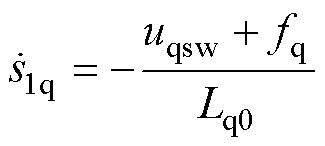
式中,uq为q轴控制输出电压;uqeq为q轴等效控制项;uqsw为q轴非线性控制项。将式(7)和式(11)代入式(9)得
 (12)
(12)
q轴非线性控制项可设计为
 (13)
(13)
式中,u1qsw为IFTSMC方案的q轴非线性控制项; 为q轴开关函数增益。
为满足 ,将式(13)代入式(12),得
 ,此时需增益
 足够大,即
足够大,即 >
> 。
。
综合式(10)的等效控制量和式(13)的非线性控制量,可得q轴综合控制电压u1q为

 (14)
(14)
定理1:对于一阶积分快速终端滑模面s1q,通过控制律设计,使得任意初始状态eq(0)能够在有限时间ts内沿滑动模态收敛至平衡状态eq=0,且收敛时间ts如式(15)所示,其求解过程见附录。
 (15)
(15)
不难发现符号函数sgn( · )的切换控制量直接作用在控制电压中。受到数字控制周期的有限时间特性约束,该切换控制将产生抖振,且抖振大小与开关增益 直接相关。令
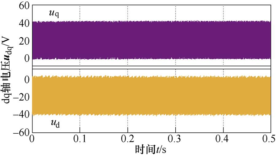
 =2×10⁴,针对本文的测试电机(参数在表1给出),图1给出了控制电压波形。显然,控制电压中存在明显抖振。
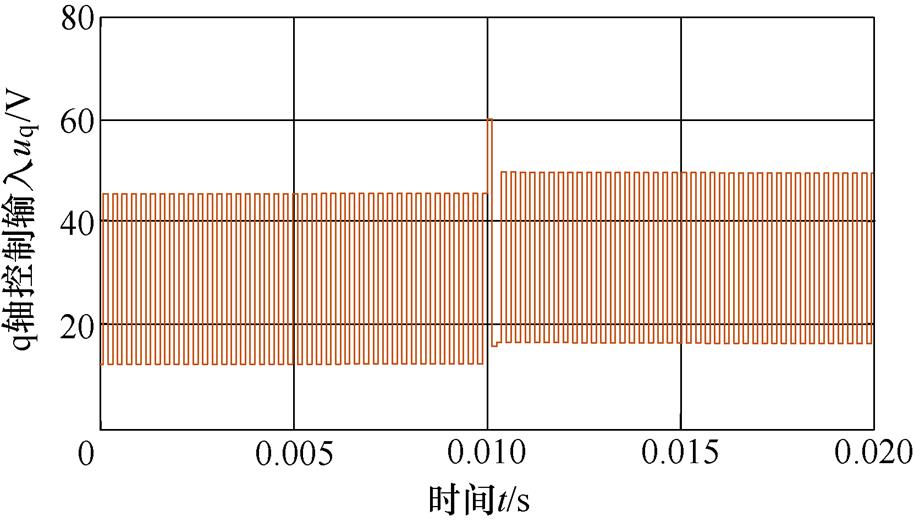
图1 IFTSMC q轴控制电压
Fig.1 IFTSMC q-axis control voltage
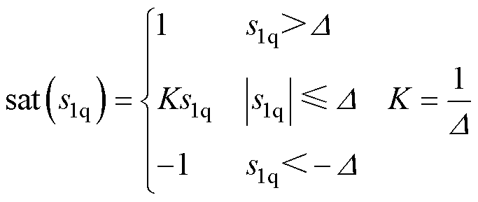
为平抑抖振,饱和函数取代符号函数,是工程应用中广泛采取的措施。此时的滑模运行为准滑动模态,即系统的运动轨迹被限制在理想滑动模态的 邻域内的模态,而非理想滑模面上。以q轴为例,用饱和函数
 代替理想滑动模态中的符号函数
 ,其表达式在式(16)中给出,图2中对饱和函数映射关系进行了描述。显然,与符号函数不同,饱和函数在边界层以外采用切换控制,在边界层内采用连续控制。
 (16)
(16)
式中, 为“边界层”。
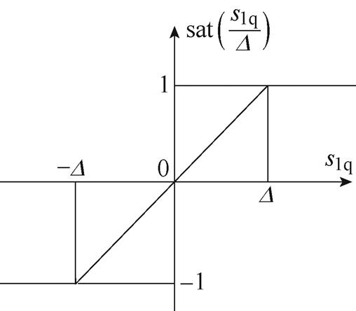
图2 饱和函数
Fig.2 Saturation function
令边界层 =2,图3给出了图1相同条件下q轴控制电压,抖振得到明显抑制。但边界层的存在影响了电流控制器精度。
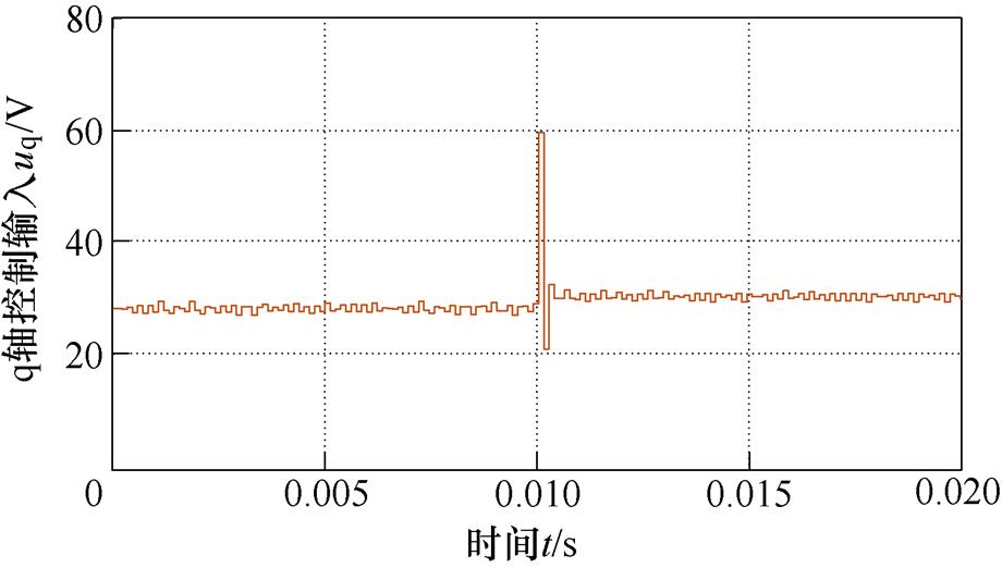
图3 BQSMC q轴控制电压
Fig.3 BQSMC q-axis control voltage
高阶滑模的优点是通过积分作用抑制控制量中的抖振。在式(8)一阶积分快速终端滑模面的基础上,设计改进后的二阶终端滑模面为
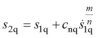 (17)
(17)
式中,s2q为q轴二阶终端滑模量;cnq为q轴滑模系数,0<cnq<1;m、n均为正奇数,且1<m/n<2。滑模面s2q的一阶微分为
 (18)
(18)
由于SOTSMC中等效控制项同式(10),为求解非线性控制项,对式(11)中s1q的一阶微分求导,有
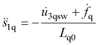 (19)
(19)
式中,u3qsw为SOTSMC的q轴非线性控制项,设计为
 (20)
(20)
式中, 为q轴开关函数增益,
 。为满足
。为满足 ,将式(19)代入式(18),得
 ,此时需增益
 足够大,即
足够大,即 。
。
由式(10)和式(20)得SOTSMC的q轴控制律为

 (21)
(21)
与第2节中式(14)相比,式(21)中的符号函数sgn( · )包含在控制电压的积分项中,从而有利于抖振抑制。令 =2×10⁶,在图1相同的条件下,此时的控制电压如图4所示。相比图1和图3中的控制电压,此时已无明显抖振。
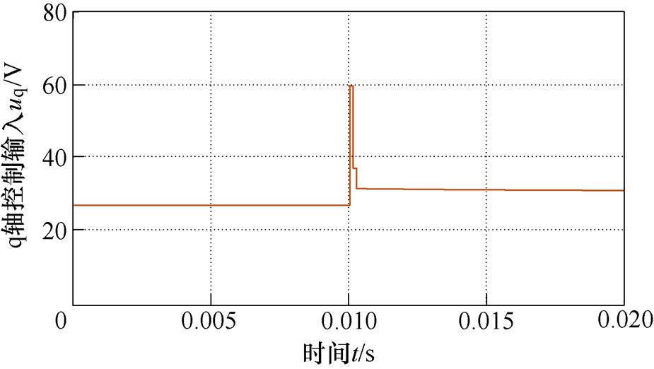
图4 SOTSMC q轴的控制电压
Fig.4 SOTSMC q-axis control voltage
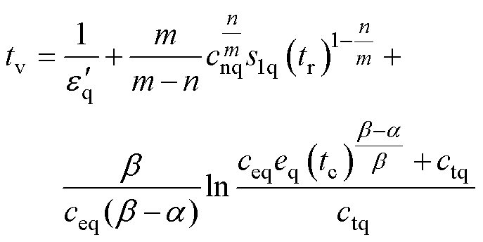
定理2:对式(17)所示二阶终端滑模面,在式(21)控制律的作用下,任意初始状态能在有限时间tv内收敛到平衡状态,其收敛时间如式(22)所示,详细求解过程见附录。
 (22)
(22)
对SMC而言,其自身存在抖振和抗扰之间的矛盾,SOTSMC虽然能够获得较好的抖振抑制性能,但其抗扰性能有所降低。如图5所示,在q轴突加10 V阶跃扰动电压,模拟电机突遇外界扰动时反电动势突变,此时一阶IFTSMC表现出最好的抗扰能力,BQSMC存在静差,SOTSMC对扰动最为敏感。因此,在提高滑模阶次抑制抖振的同时,需要对扰动进行补偿,以提高系统抗扰性能。
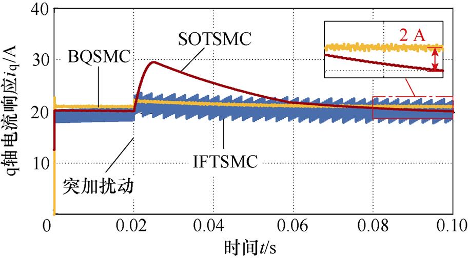
图5 q轴突加阶跃扰动后的电流响应
Fig.5 Current response of q-axis step disturbance
将定子电阻电压降、交叉耦合项、反电动势项及系统不确定性项视为总扰动。此时,q轴被控对象重新表示为
 (23)
(23)
其中

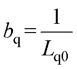
式中,dq为q轴总扰动。
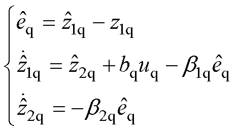
令q轴扩张状态变量z1q=iq,z2q=dq,则ESO可设计为
 (24)
(24)
式中,上标“ ”表示估计值;
 、
、 为q轴ESO的误差增益。
数字控制系统中存在延迟,第k个控制周期中所获得的电流信号,实际是k-1周期内的电流,这个延迟将影响扰动的估计与补偿。为此,引入Smith预估器对采样电流进行一拍超前预估,以补偿采样延迟影响。Smith预估器设计为
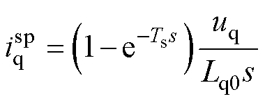 (25)
(25)
式中, 为q轴预估补偿电流;Ts为一个采样周期。采样电流的一拍超前预估值
 可表示为
可表示为
 (26)
(26)
将预估电流用于ESO,即状态变量 ,可以减小滞后对ESO的不利影响,本文将其命名为EESO。将EESO的扰动估计用于补偿。于是,SOTSMC q轴电流控制律u4q如式(27)所示,控制框图如图6a所示,图中,
 为q轴外部扰动。

 (27)
(27)
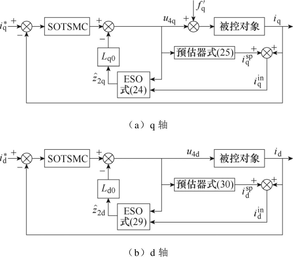
图6 EESO+SOTSMC控制框图
Fig.6 Block diagram of EESO+SOTSMC
d轴控制器设计同理。d轴被控对象为
 (28)
(28)
其中

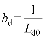
式中,dd为d轴总扰动。
令d轴扩张状态变量z1d=id,z2d=dd,则ESO可设计为
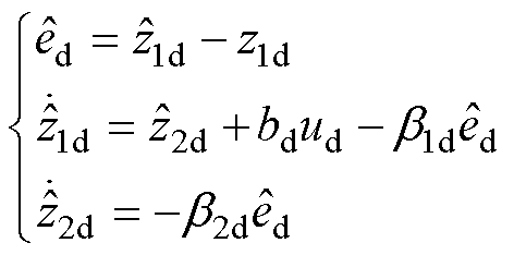 (29)
(29)
式中, 、
、 为d轴ESO的误差增益。
d轴Smith预估器设计为
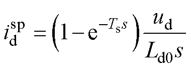 (30)
(30)
式中, 为d轴预估补偿电流。采样电流的一拍超前预估值
 可表示为
可表示为
 (31)
(31)
此时SOTSMC d轴电流控制律u4d如式(32)所示,控制框图如图6b所示。

 (32)
(32)
式中, 为电流id的参考信号;ed为d轴电流跟踪误差;s1d为d轴一阶积分快速终端滑模量;s2d为d轴二阶终端滑模量;ced、ctd、cnd为d轴滑模系数;
 为d轴开关函数增益。
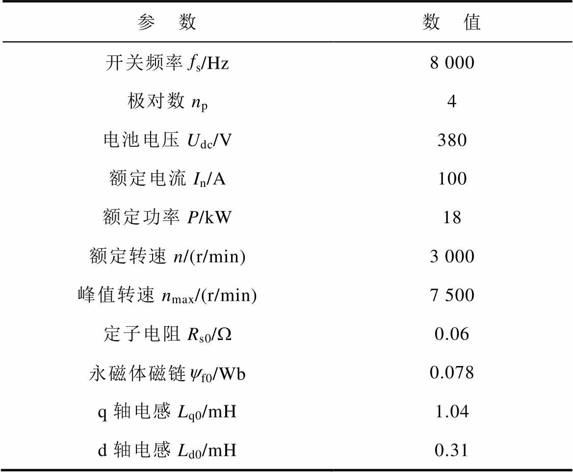
为验证基于EESO的SOTSMC策略的有效性,在18 kW-IPMSM矢量控制平台上进行了实验验证。IPMSM参数见表1,其原理框图如图7所示,对应实物照片如图8所示。控制器采用TI公司的TM320F28379芯片,通过旋转变压器获取IPMSM实际转子位置。逆变器开关频率和死区时间分别设置为8 kHz和2.5 ms。图8中,采用双电机对拖加载模式,IPMSM为测试电机,感应电机(Induction Motor, IM)为负载电机。
IPMSM采用矢量控制,其原理框图如图9所示。实验对比测试了四种电流控制方案:IFTSMC、BQSMC、SOTSMC、EESO+SOTSMC。综合考虑到2~5节中的李雅普洛夫稳定性、抖振大小和收敛速度的理论分析,对控制参数进行了设计,各方案的控制参数见表2。
表1 内置式永磁同步电机参数
Tab.1 Parameters of IPMSM
参 数数 值 开关频率fs/Hz8 000 极对数np4 电池电压Udc/V380 额定电流In/A100 额定功率P/kW18 额定转速n/(r/min)3 000 峰值转速nmax/(r/min)7 500 定子电阻Rs0/W0.06 永磁体磁链yf0/Wb0.078 q轴电感Lq0/mH1.04 d轴电感Ld0/mH0.31
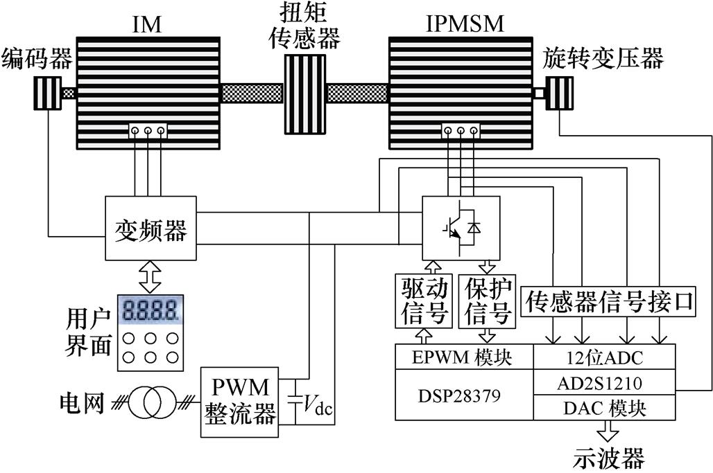
图7 PMSM矢量控制系统原理框图
Fig.7 PMSM vector control system schematic diagram
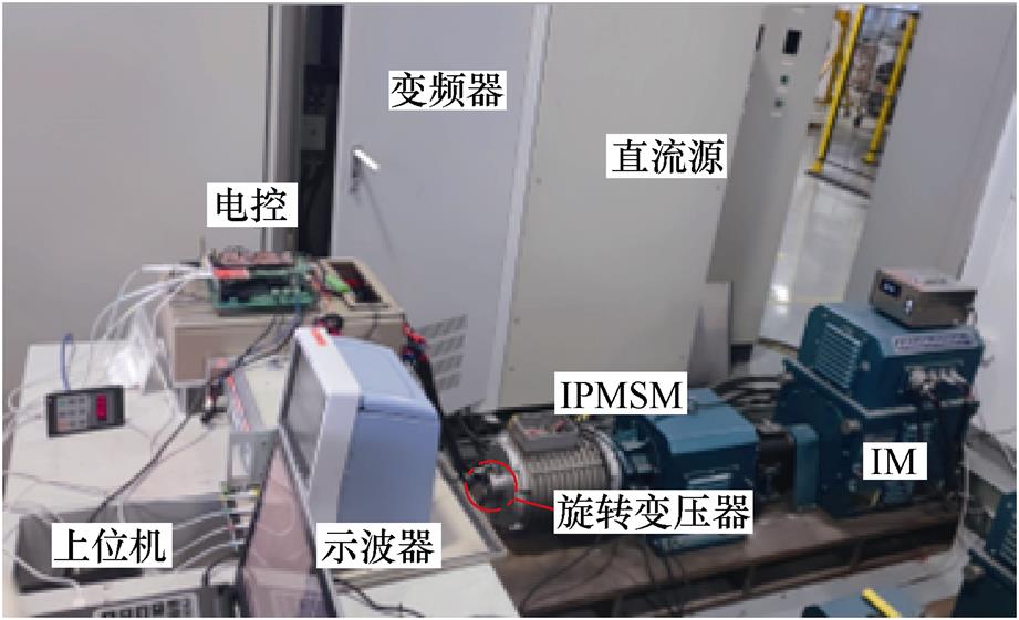
图8 18 kW-IPMSM对拖实验平台
Fig.8 Experimental test setup of 18 kW-IPMSM drive
图10记录了电机转速1 000 r/min时四种电流控制方案最终产生的控制电压。实验中IPMSM工作在电流环控制模式,各方案控制电压抖振幅值描绘在图11中。可见,采用BQSMC和SOTSMC方案对抖振都起抑制作用,但EESO+SOTSMC方案的抑制能力更优。图12为电机转速3 000 r/min时四种电流控制方案最终产生的控制电压,电压抖振幅值描绘在图13中。随着转速的增高,抖振幅度有所增加,但EESO+SOTSMC方案的抖振依然最小,明显低于其他方案。
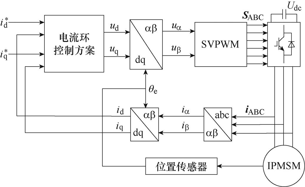
图9 PMSM矢量控制系统原理框图
Fig.9 PMSM vector control system schematic diagram
表2 四种方案的控制参数
Tab.2 Control parameters of four schemes
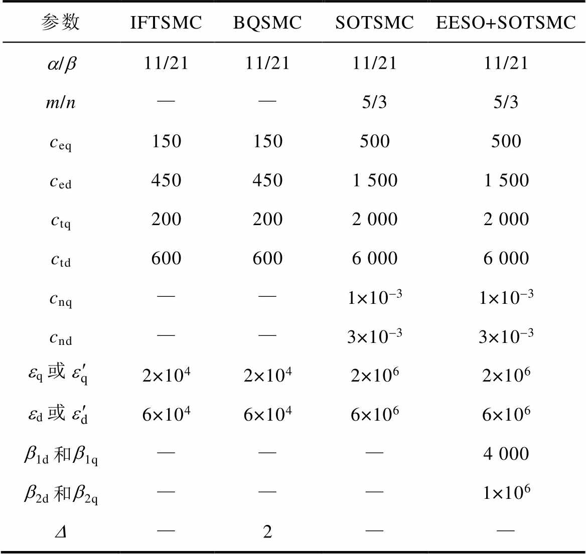
参数IFTSMCBQSMCSOTSMCEESO+SOTSMC a/b11/2111/2111/2111/21 m/n——5/35/3 ceq150150500500 ced4504501 5001 500 ctq2002002 0002 000 ctd6006006 0006 000 cnq——1×10-31×10-3 cnd——3×10-33×10-3 eq或2×1042×1042×1062×106 ed或6×1046×1046×1066×106 b1d和b1q———4 000 b2d和b2q———1×10⁶ —2——
(a)IFTSMC
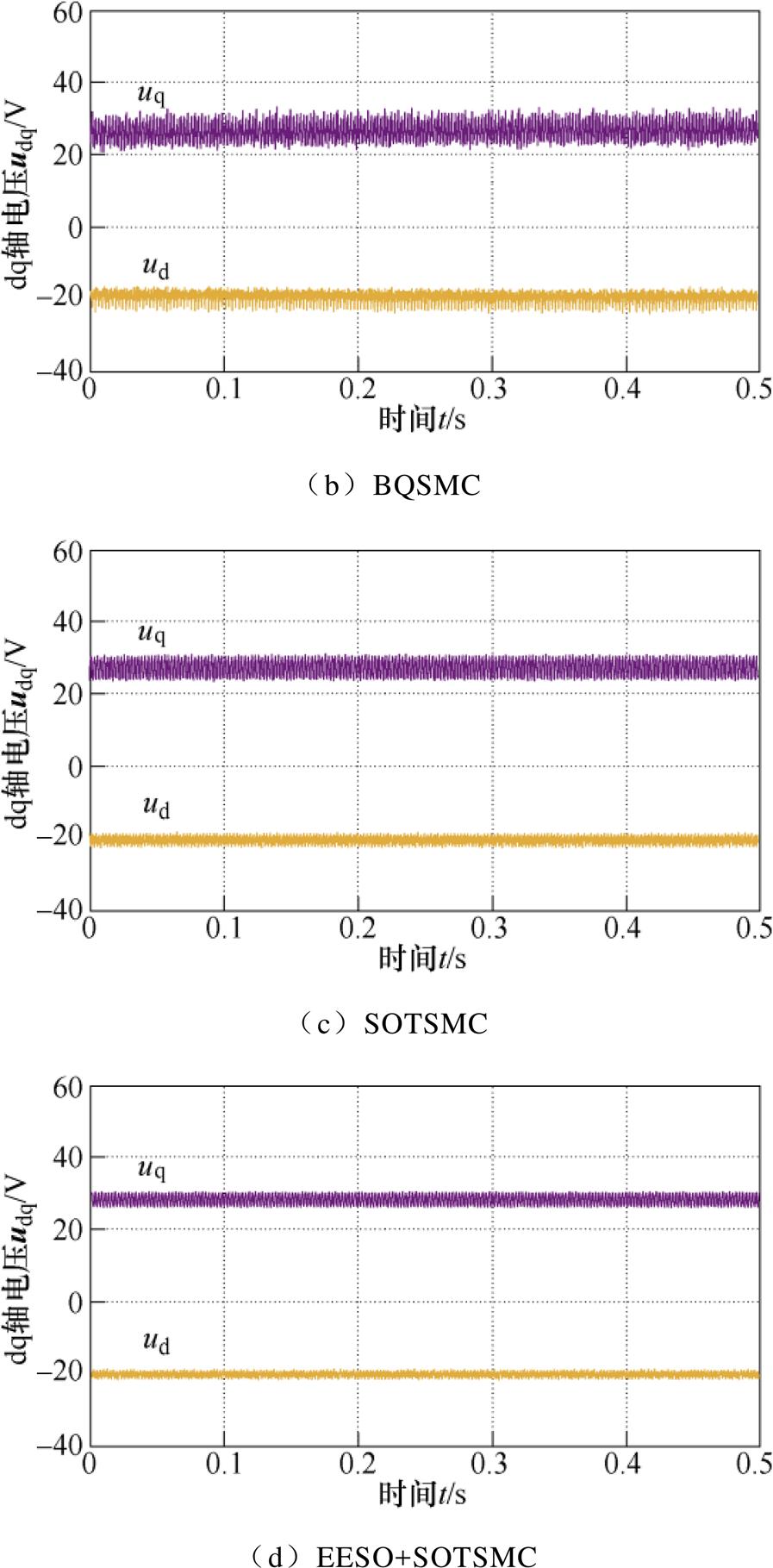
图10 1 000 r/min时d、q轴控制电压
Fig.10 Controls input of d、q axis at 1 000 r/min
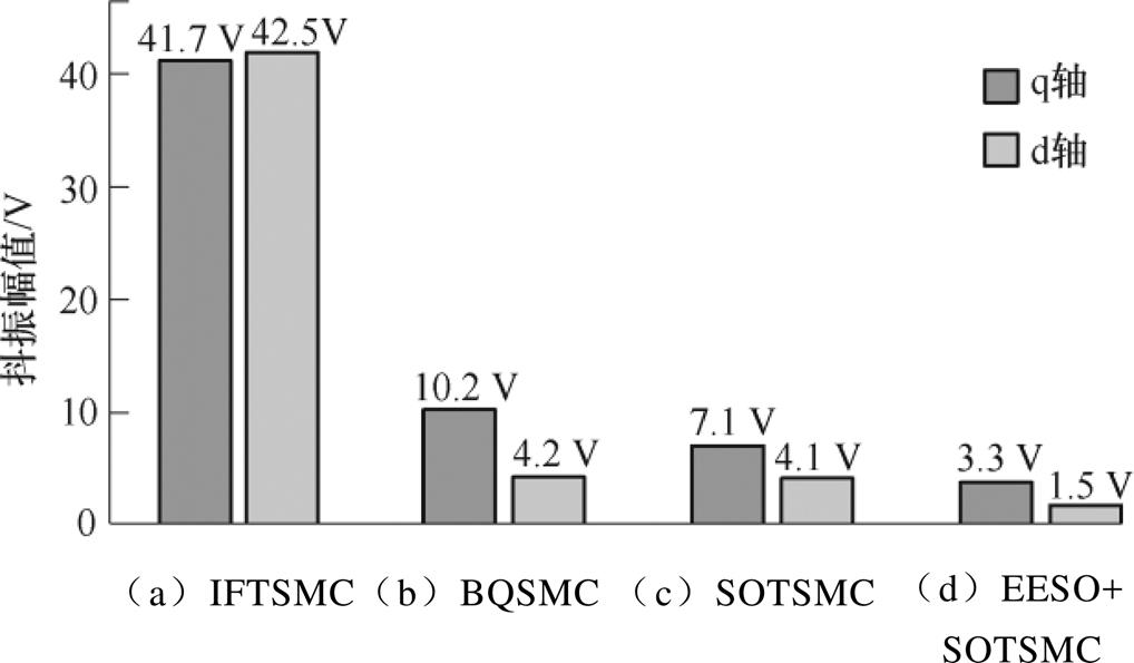
图11 1 000 r/min时四种控制方案的抖振幅值
Fig.11 Chattering amplitude of four control schemes at 1 000 r/min
为考察抖振对电流跟踪性能的影响,对四种控制方案下电流阶跃响应进行了实验测试。实验中,d轴参考电流指令保持恒定值 =-50 A,q轴电流指1 000 r/min工况下四种控制方案的实验结果和跟踪电流误差幅值。由图14可见,四种方案的阶跃响应时间均小于15拍,其中图14d中由于控制延迟补偿作用,响应时间更短,得以7拍响应,且解耦性能优于其他三种方案。可见,1 000 r/min时本文所提EESO+SOTSMC方案有更好的电流跟踪动态性能。将图15与图11对比可见,相同转速下控制电压抖振越大,对电流误差幅值的影响越大,图15中采用SOTSMC方案的电流误差幅值小于IFTSMC的20%,有更好的电流稳态性能。图16和图17分别为3 000 r/min工况下四种控制方案的实验结果和跟踪电流误差幅值。转速升高,电流响应时间与跟踪误差也有所增加,但本文所提EESO+SOTSMC方案的动态和稳态性能依然优于其他三种方案。
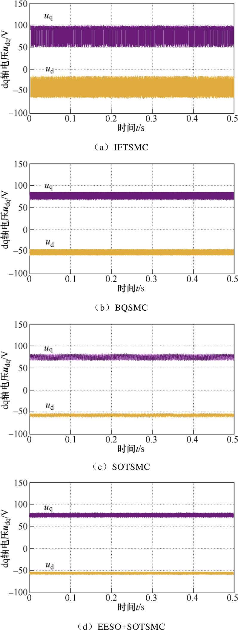
图12 3 000 r/min时d、q轴控制电压
Fig.12 Controls input of d、q axis at 3 000 r/min
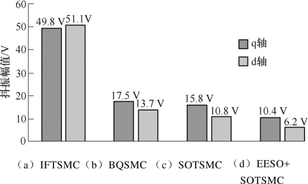
图13 3 000 r/min时四种控制方案的抖振幅值
Fig.13 Chattering amplitude of four control schemes at 3 000 r/min
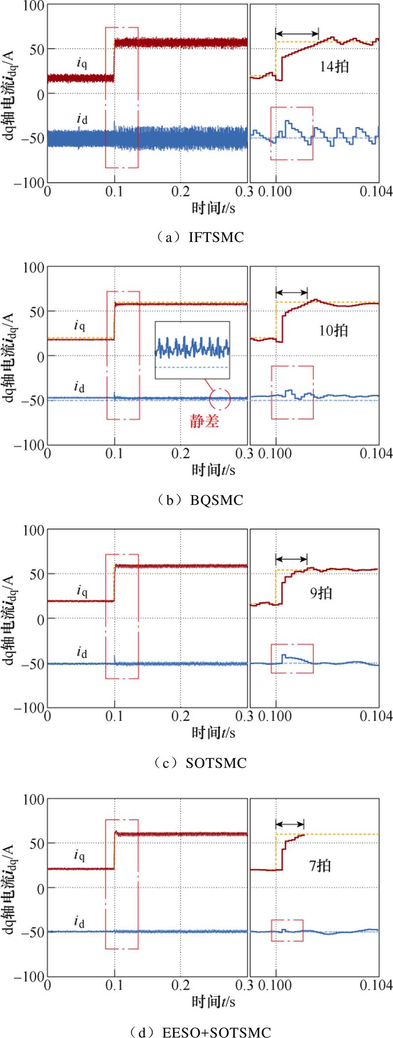
图14 1 000 r/min时电流阶跃响应
Fig.14 Diagram of current step response at 1 000 r/min
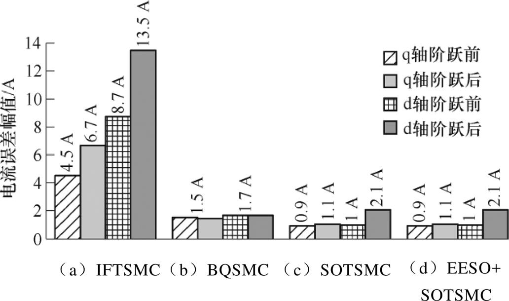
图15 1 000 r/min时四种控制方案的跟踪电流误差幅值
Fig.15 Tracking current error amplitude of four control schemes at 1 000 r/min
图18和图19分别记录了1 000 r/min和3 000 r/min时EESO+SOTSMC方案的相电流波形,电流波形平滑无明显畸变。
图20、图21中分别为1 000 r/min和3 000 r/min实验过程中EESO+SOTSMC方案的滑模面变化过程,电流给定阶跃瞬间滑模量突变,随后能快速收敛至平衡态。由定理2中式(22)可知,收敛时间与转速无关,算得d、q轴二阶终端滑模量分别在0.4 ms、1.2 ms内收敛至平衡点,与图中实验结果一致。
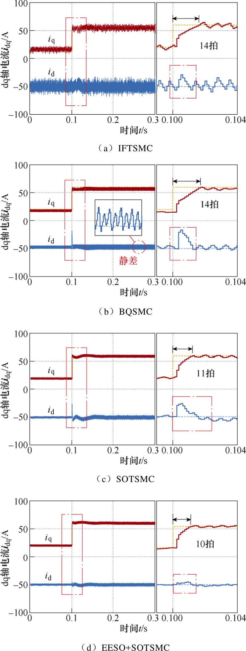
图16 3 000 r/min时电流阶跃响应
Fig.16 Diagram of current step response at 3 000 r/min
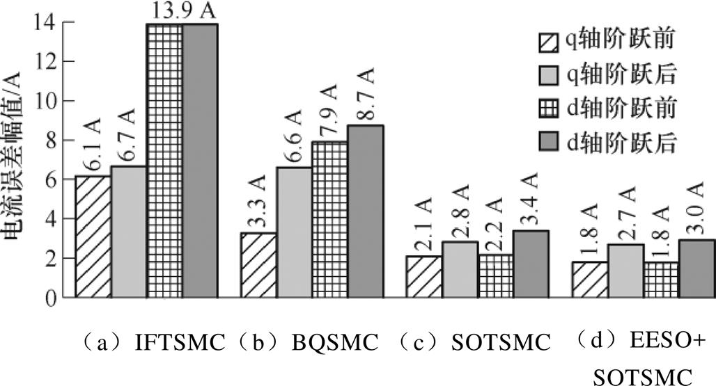
图17 3 000 r/min时四种控制方案的跟踪电流误差幅值
Fig.17 Tracking current error amplitude of four control schemes at 3 000 r/min
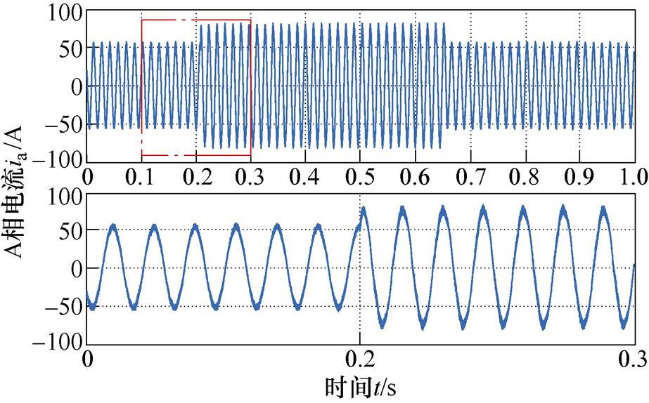
图18 1 000 r/min时EESO+SOTSMC的ia及局部放大
Fig.18 ia and its detail view of EESO+SOTSMC at 1 000 r/min
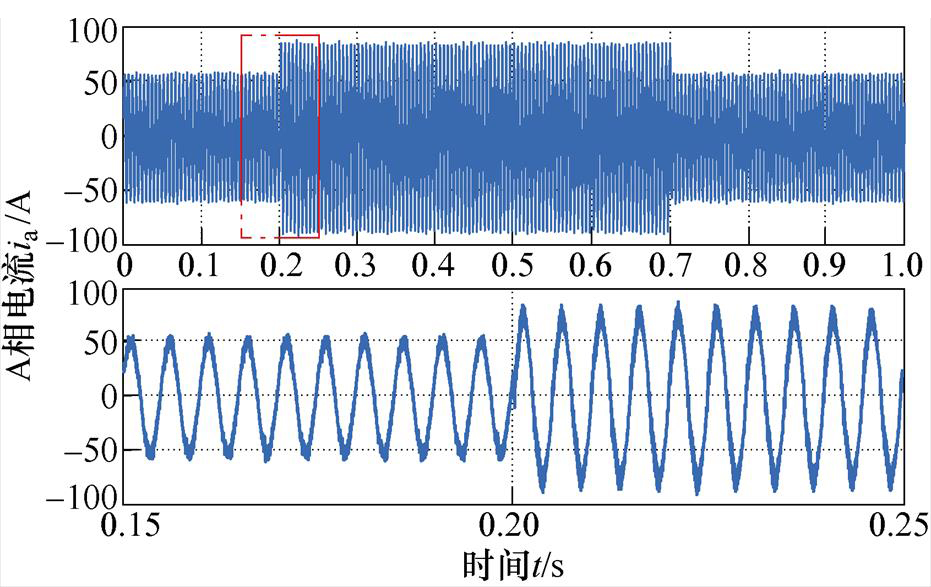
图19 3 000 r/min时EESO+SOTSMC的ia及局部放大
Fig.19 ia and its detail view of EESO+SOTSMC at 3 000 r/min
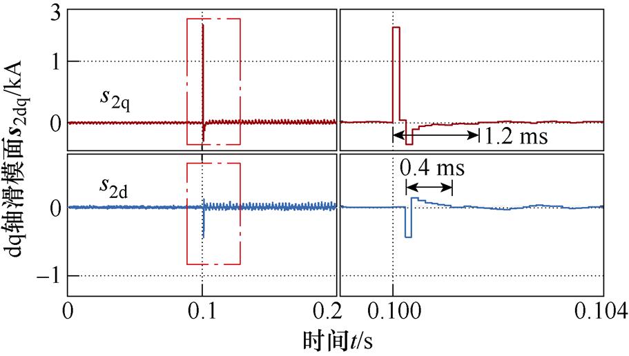
图20 1 000 r/min时EESO+SOTSMC滑模面
Fig.20 Sliding mode surface of EESO+SOTSMC at 1 000 r/min
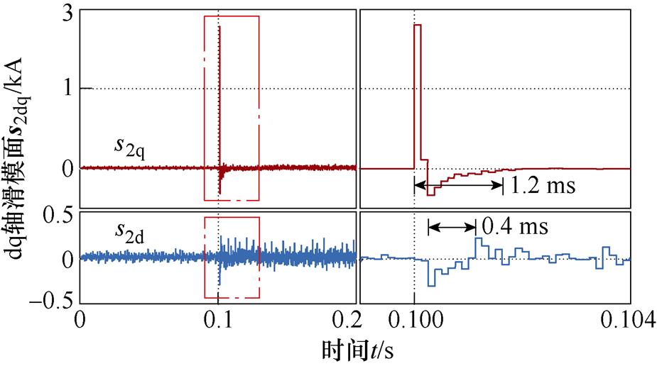
图21 3 000 r/min时EESO+SOTSMC滑模面
Fig.21 Sliding mode surface of EESO+SOTSMC at 3 000 r/min
为检验四种控制方案的抗扰性能,当1 000 r/min时在电机q轴电压输入中突加10 V阶跃扰动,相当于此时定子电压的30%。参考电流 =-50 A、
 = 20 A,实验结果如图22和图23所示,可见IFTSMC方案对扰动抑制能力最强,但该方案对外部干扰的抑制能力是通过控制量的高频抖振换取的。在3个抑制抖振的控制方案中,BQSMC方案突加阶跃扰动后电流存在约2 A的跟踪静差;采用SOTSMC方案能消除稳态静差,但抗扰能力减弱;相较之下,EESO+SOTSMC方案突加阶跃扰动后的电流扰动幅值小于SOTSMC方案的30%,收敛时间缩短50%。在相同条件下,图24、图25中记录3 000 r/min时的实验结果。此时,EESO+SOTSMC方案电流偏差幅值小于SOTSMC方案的60%,收敛时间缩短20%。
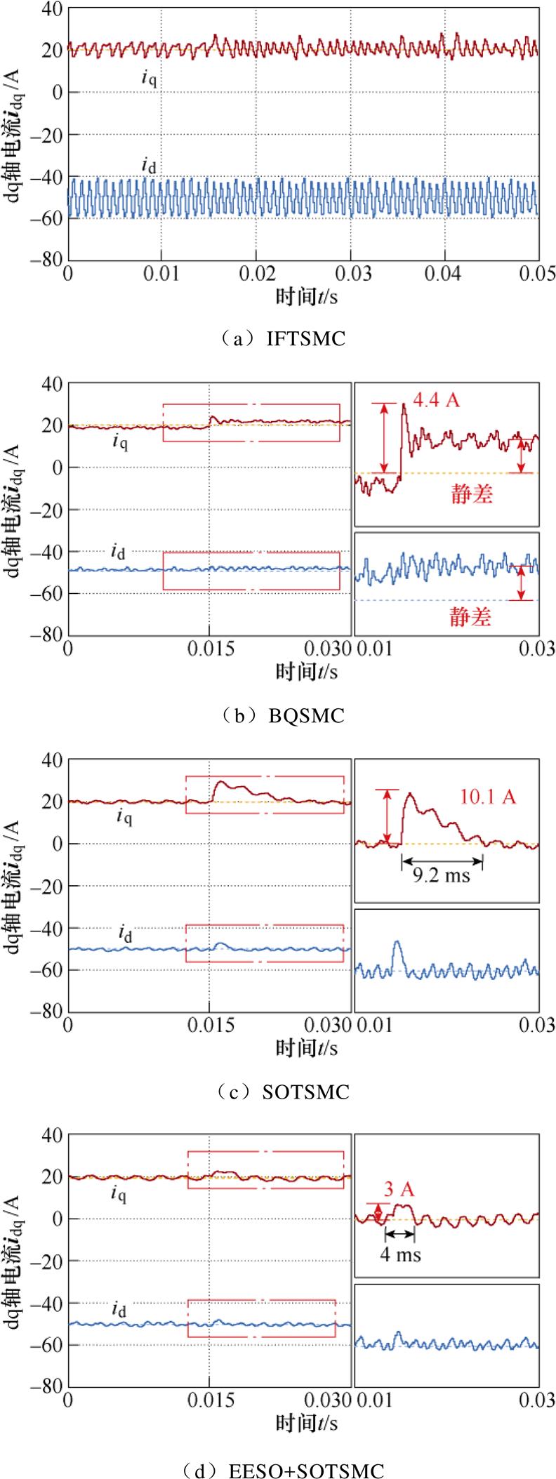
图22 1 000 r/min时q轴突加阶跃干扰时实验结果
Fig.22 Experimental results of q-axis step disturbance at 1 000 r/min
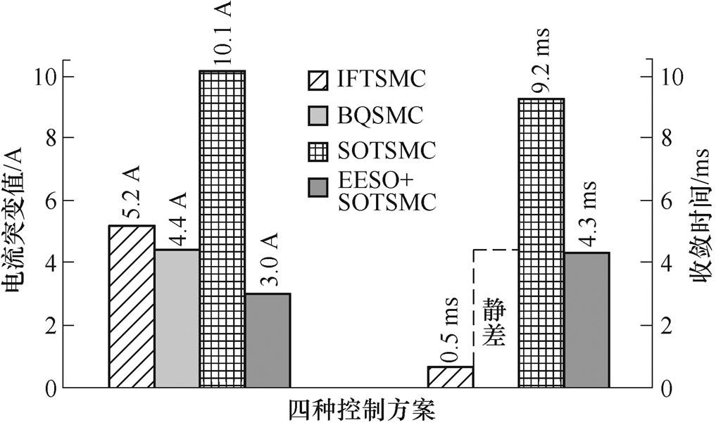
图23 1 000 r/min时四种控制方案的抗扰性能比较
Fig.23 Comparison of disturbance resistance performance of four control schemes at 1 000 r/min
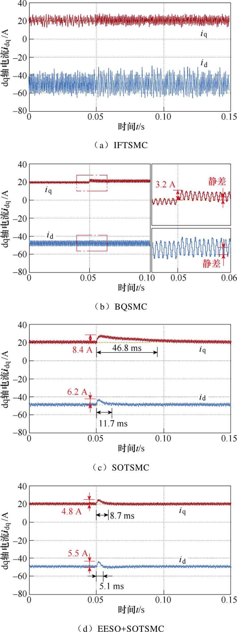
图24 3 000 r/min时q轴突加阶跃干扰时实验结果
Fig.24 Experimental results of q-axis step disturbance at 3 000 r/min
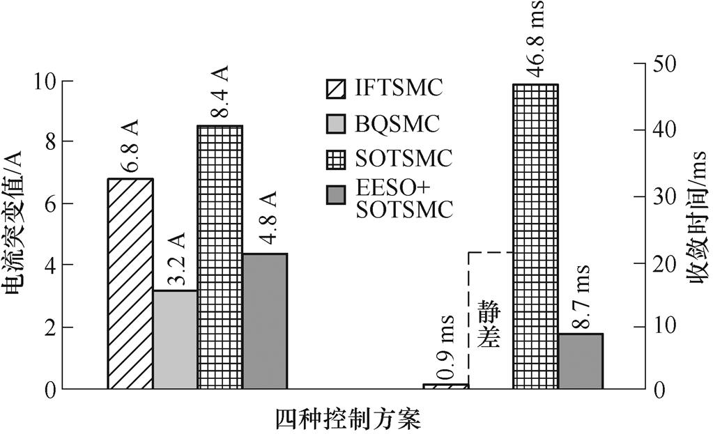
图25 3 000 r/min时四种控制方案的抗扰性能比较
Fig.25 Comparison of disturbance resistance performance of four control schemes at 3 000 r/min
本文针对PMSM传统电流滑模控制抖振大、抖振抑制与抗扰性之间存在矛盾的问题,提出一种结合EESO和SOTSMC设计的电流环控制器,通过理论分析与实验研究可得出以下结论:
1)本文所提的EESO+SOTSMC电流环控制方案能较好地抑制系统抖振对电流的影响。额定转速时的电压抖振幅值小于传统的一阶滑模控制方案的1/5。解决了传统滑模电流控制策略因抖振大而造成电流稳态精度低、波动大的问题,改善系统稳态性能,且确保了电机电流状态能够在有限时间内实现参考信号的跟踪。
2)本文所提的EESO+SOTSMC电流环控制方案能有效增强系统抗扰能力,改善系统动态性能。由于SMC在抑制抖振和扰动之间存在矛盾,SOTSMC的设计降低了系统抖振,但其抗扰能力变差。本文设计EESO,有效估计系统扰动并在控制律中进行前馈补偿,当额定转速系统突加阶跃扰动后,电流扰动幅值小于SOTSMC方案的70%,收敛时间仅为SOTSMC方案的1/5,以解决抑制抖振和扰动之间存在的矛盾问题。
3)本文所提的EESO+SOTSMC电流环控制方案中引入Smith预估器,通过预测超前一拍的电流,减小系统中时间滞后的影响,从而减小由此造成的系统干扰和耦合影响。
附 录
1. ts求解过程
令一阶积分快速终端滑模面为
 (A1)
(A1)
式中, 为状态变量;c1、c2为滑模系数,c1、c2>0;a 和b(a>b)为正奇数;
 。
。
对式(A1)求导变换后得
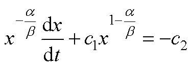 (A2)
(A2)
令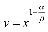 ,则
,则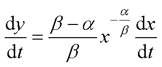 。式(A2)写为
 (A3)
(A3)
由于一阶线性微分方程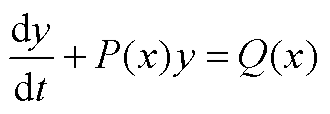 的通解为
的通解为
 (A4)
(A4)
则式(A3)的解为
 (A5)
(A5)
t=0时,C=y(0),式(A5)变为
 (A6)
(A6)
当系统收敛到平衡状态x=0时,y=0,t=ts。
由式(A6)可求得,理想状态下,在滑模面上,从任意初始状态x(0)≠0收敛到平衡状态x=0的时间为
 (A7)
(A7)
通过设定c1、c2、p、q可使系统在有限时间ts内到达平衡状态。
2. tv求解过程
令一阶积分快速终端滑模面为
 (A8)
(A8)
一阶积分快速终端滑模面为
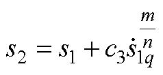 (A9)
(A9)
式中,c3为滑模系数;m、n均为正奇数,且1<m/n<2。
令滑模面s2的指数趋近律为
 (A10)
(A10)
由指数趋近律式可知,指数项-qs2能保证当滑模量s2较大时,以较大的速度趋近平衡点;等速趋近项 使s2接近平衡点时,趋近速度是e 而不是0,以保证有限时间到达平衡点。运算可得s2滑模面趋近平衡态的时间tr为
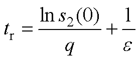 (A11)
(A11)
当系统状态在滑动模态s2上运动时,当tc>tr,s2(tc)=0。由式(A9)可求得tr~tc时刻间的s1状态为
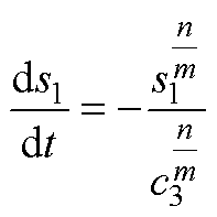 (A12)
(A12)
若s1(tc)=0,对等式两边积分可求得s1的收敛时间 tc为
 (A13)
(A13)
当t≥tc时,状态x沿s1(t)=0运动至收敛到x(tv)=0。由定理1可得收敛时间tv为
 (A14)
(A14)
参考文献
[1] 刘善宏, 杨淑英, 李浩源, 等. 基于旋转坐标系解调的内置式永磁同步电机旋转高频注入法位置观测[J]. 电工技术学报, 2020, 35(4): 708-716.
Liu Shanhong, Yang Shuying, Li Haoyuan, et al. Rotating high frequency signal injection based on interior permanent magnet synchronous motor rotor position estimation with the demodulation imple- mented on the synchronous reference frame[J]. Transactions of China Electrotechnical Society, 2020, 35(4): 708-716.
[2] 徐奇伟, 熊德鑫, 陈杨明, 等. 基于新型高频纹波电流补偿方法的内置式永磁同步电机无传感器控制[J]. 电工技术学报, 2023, 38(3): 680-691.
Xu Qiwei, Xiong Dexin, Chen Yangming, et al. Research on sensorless control strategy of IPMSM based on new high frequency ripple current com- pensation method[J]. Transactions of China Elec- trotechnical Society, 2023, 38(3): 680-691.
[3] 杨淑英, 王玉柱, 储昭晗, 等. 基于增益连续扩张状态观测器的永磁同步电机电流解耦控制[J]. 中国电机工程学报, 2020, 40(6): 1985-1997.
Yang Shuying, Wang Yuzhu, Chu Zhaohan, et al. Current decoupling control of PMSM based on an extended state observer with continuous gains[J]. Proceedings of the CSEE, 2020, 40(6): 1985-1997.
[4] 邱伟康, 陈宇, 文刚, 等. 九开关双馈风力发电系统的恒定开关频率电流滑模控制方法[J]. 中国电机工程学报, 2018, 38(20): 6134-6144.
Qiu Weikang, Chen Yu, Wen Gang, et al. Constant switching frequency current sliding mode control method for nine-switch-converter-based doubly-fed wind generation system[J]. Proceedings of the CSEE, 2018, 38(20): 6134-6144.
[5] 赵文祥, 刘桓, 陶涛, 等. 基于虚拟信号和高频脉振信号注入的无位置传感器内置式永磁同步电机MTPA控制[J]. 电工技术学报, 2021, 36(24): 5092- 5100.
Zhao Wengxiang, Liu Huan, Tao Tao, et al. MTPA control of sensorless IPMSM based on virtual signal and high-frequency pulsating signal injection[J]. Transactions of China Electrotechnical Society, 2021, 36(24): 5092-5100.
[6] 王爽, 冯坚栋, 丁雪, 等. 基于最优开环截止频率学习的永磁伺服系统PI控制器参数整定方法[J]. 电工技术学报, 2017, 32(21): 44-54.
Wang Shuang, Feng Jiandong, Ding Xue, et al. PI controllers tuning method of permanent magnet servo system based on optimal open-loop cut-off frequency learning[J]. Transactions of China Electrotechnical Society, 2017, 32(21): 44-54.
[7] Kang B J, Liaw C M. A robust hysteresis current- controlled PWM inverter for linear PMSM driven magnetic suspended positioning system[J]. IEEE Transactions on Industrial Electronics, 2001, 48(5): 956-967.
[8] 王志彬, 朱景伟, 赵锡阳, 等. 永磁容错轮缘推进电机预测占空比电流滞环控制[J]. 电工技术学报, 2023, 38(3): 670-679.
Wang Zhibin, Zhu Jingwei, Zhao Xiyang, et al. Predictive duty cycle current hysteresis control for fault-tolerant permanent magnet rim drive motor[J]. Transactions of China Electrotechnical Society, 2023, 38(3): 670-679.
[9] 张珍睿, 刘彦呈, 陈九霖, 等. 永磁同步电机幅值控制集模型预测控制策略[J]. 电工技术学报, 2022, 37(23): 6126-6134.
Zhang Zhenrui, Liu Yancheng, Chen Jiulin, et al. Amplitude control set model predictive control strategy for permanent magnet synchronous motor[J]. Transactions of China Electrotechnical Society, 2022, 37(23): 6126-6134.
[10] 周奇勋, 刘帆, 吴紫辉, 等. 永磁同步电机转矩与定子磁链模型预测控制预测误差补偿方法[J]. 电工技术学报, 2022, 37(22): 5728-5739.
Zhou Qixun, Liu Fan, Wu Zihui, et al. Model predictive torque and stator flux control method for PMSMs with prediction error compensation[J]. Transactions of China Electrotechnical Society, 2022, 37(22): 5728-5739.
[11] Gao Jinqiu, Gong Chao, Li Wenzhen, et al. Novel compensation strategy for calculation delay of finite control set model predictive current control in PMSM[J]. IEEE Transactions on Industrial Elec- tronics, 2020, 67(7): 5816-5819.
[12] Niu Feng, Chen Xi, Huang Shaopo, et al. Model predictive current control with adaptive-adjusting timescales for PMSMs[J]. CES Transactions on Elec- trical Machines and Systems, 2021, 5(2): 108-117.
[13] Utkin V. Variable structure systems with sliding modes[J]. IEEE Transactions on Automatic Control, 1977, 22(2): 212-222.
[14] 刘金琨. 滑模变结构控制MATLAB仿真: 基本理论与设计方法[M]. 3版. 北京: 清华大学出版社, 2015.
[15] Sun Qingguo, Zhu Xiaolei, Niu Feng. Sensorless control of permanent magnet synchronous motor based on new sliding mode observer with single resistor current reconstruction[J]. CES Transactions on Electrical Machines and Systems, 2022, 6(4): 378-383.
[16] 张袅娜. 终端滑模控制理论及应用[M]. 北京: 科学出版社, 2011.
[17] Xu S S D, Chen C C, Wu Zhenglun. Study of nonsingular fast terminal sliding-mode fault-tolerant control[J]. IEEE Transactions on Industrial Elec- tronics, 2015, 62(6): 3906-3913.
[18] 冯勇, 鲍晟, 余星火. 非奇异终端滑模控制系统的设计方法[J]. 控制与决策, 2002, 17(2): 194-198.
Feng Yong, Bao Sheng, Yu Xinghuo. Design method of non-singular terminal sliding mode control systems[J]. Control and Decision, 2002, 17(2): 194- 198.
[19] Chiu C S. Derivative and integral terminal sliding mode control for a class of MIMO nonlinear systems[J]. Automatica, 2012, 48(2): 316-326.
[20] 王艳敏, 冯勇, 陆启良. 永磁同步电动机的无抖振滑模控制系统设计[J]. 电机与控制学报, 2008, 12(5): 514-519.
Wang Yanmin, Feng Yong, Lu Qiliang. Design of free-chattering sliding mode control systems for permanent magnet synchronous motor[J]. Electric Machines and Control, 2008, 12(5): 514-519.
[21] Slotine J J, Sastry S S. Tracking control of non-linear systems using sliding surfaces with application to robot manipulators[C]//American Control Conference, San Francisco, CA, USA, 2009: 132-135.
[22] 金鸿雁, 赵希梅, 原浩. 永磁直线同步电机动态边界层全局互补滑模控制[J]. 电工技术学报, 2020, 35(9): 1945-1951.
Jin Hongyan, Zhao Ximei, Yuan Hao. Dynamic boundary layer global complementary sliding mode control for permanent magnet linear synchronous motor[J]. Transactions of China Electrotechnical Society, 2020, 35(9): 1945-1951.
[23] Xu Yongxiang, Li Shaobin, Zou Jibin. Integral sliding mode control based deadbeat predictive current control for PMSM drives with disturbance rejection[J]. IEEE Transactions on Power Electronics, 2022, 37(3): 2845-2856.
[24] 宁博文, 周凤星, 卢少武. 基于高阶滑模速度控制器的异步电机模型预测转矩控制[J]. 控制与决策, 2021, 36(4): 953-958.
Ning Bowen, Zhou Fengxing, Lu Shaowu. A model predictive torque control for induction motor based on high order sliding mode speed controller[J]. Control and Decision, 2021, 36(4): 953-958.
[25] Zhang Kang, Wang Limei, Fang Xin. High-order fast nonsingular terminal sliding mode control of permanent magnet linear motor based on double dis- turbance observer[J]. IEEE Transactions on Industry Applications, 2022, 58(3): 3696-3705.
[26] 方馨, 王丽梅, 张康. 基于扰动观测器的永磁直线电机高阶非奇异快速终端滑模控制[J]. 电工技术学报, 2023, 38(2): 409-421.
Fang Xin, Wang Limei, Zhang Kang. High order nonsingular fast terminal sliding mode control of permanent magnet linear motor based on disturbance observer[J]. Transactions of China Electrotechnical Society, 2023, 38(2): 409-421.
[27] 毛海杰, 李炜, 蒋栋年, 等. 基于线性扩张状态观测器的永磁同步电机状态估计与性能分析[J]. 电工技术学报, 2019, 34(10): 2155-2165.
Mao Haijie, Li Wei, Jiang Dongnian, et al. State estimation and performance analysis based on linear extended state observer for permanent magnet synchronous motor[J]. Transactions of China Elec- trotechnical Society, 2019, 34(10): 2155-2165.
[28] Diab A M, Yeoh S S, Bozhko S, et al. Enhanced active disturbance rejection current controller for permanent magnet synchronous machines operated at low sampling time ratio[J]. IEEE Journal of Emerging and Selected Topics in Industrial Electronics, 2022, 3(2): 230-241.
[29] 潘子昊, 卜飞飞, 轩富强, 等. 基于Smith预估器的永磁电机高动态响应电流环控制策略[J]. 电工技术学报, 2020, 35(9): 1921-1930.
Pan Zihao, Bu Feifei, Xuan Fuqiang, et al. High- dynamic-response current loop control strategy of permanent magnet motor based on Smith predictor[J]. Transactions of China Electrotechnical Society, 2020, 35(9): 1921-1930.
[30] Qu Lizhi, Qiao Wei, Qu Liyan. Active-disturbance- rejection-based sliding-mode current control for permanent-magnet synchronous motors[J]. IEEE Transactions on Power Electronics, 2021, 36(1): 751- 760.
Abstract As the bottom control link of the interior permanent magnet synchronous motor (IPMSM) system, the current control plays a crucial role in the system’s performance. The sliding-mode current control (SMCC) of the IPMSM has the merit of high robustness to parameter mismatch. However, the control accuracy in practice is subjected to sliding-mode chattering, and its suppression would negatively affect the anti-disturbance performance. In order to suppress the chattering of the traditional first-order SMCC system and ensure the excellent anti-disturbance performance of the system, an enhanced extended state observer (ESO) based second-order terminal sliding mode (TSM) control strategy is proposed to improve the final performance of the stator current control.
The structure of the second-order TSM surface is that an integral fast TSM surface is nested into the second-order non-singular TSM surface. The coefficients of the integral fast TSM surface guarantee the rapidity of stator current convergence, and the overshoot is not obvious. The integral term makes the system feedback state have no steady-state current error. The second-order TSM control has superior chattering suppression ability and retains the robustness of switching function to parameter deviation. By introducing the EESO, the disturbance is estimated and compensated, which is beneficial to easing the confliction between chattering suppression and anti-disturbance.A Smith predictor is designed to address negative effects of the delay inherent to the digital control. Consequently, the disturbance is suppressed well.
Experiments based on an 18 kW-IPMSM hardware platform verify the current control strategy. The voltage chattering amplitude of the second-order TSM control strategy is less than 20% of that of the traditional SMCC strategy at the rated speed. The amplitude of the current tracking error is affected by voltage chattering. The current tracking accuracy is high, the three-phase currents are smooth, and the distortion is low when voltage chattering becomes small. The feedback current can track the reference signal within 2 ms to achieve the engineering rapidity of the current loop. To simulate the dramatic change of back electromotive force caused by external interference, a 10 V step disturbance is suddenly added to the q-axis input of IPMSM. The disturbance recovered within 10 ms after the current change.
The strategy solves the problems of large chattering and the contradiction between chattering and disturbance suppression in the traditional SMCC of IPMSM. The results of theoretical analysis and experimental research are as follows. (1) The proposed strategy can better suppress the influence of voltage chattering on the current tracking accuracy. It improves the steady-state and dynamic performance of the system, solves the problems of low steady-state accuracy and large fluctuation caused by large chattering in traditional SMCC strategy, and ensures that the motor current state can track the reference signal in a limited time. (2) The strategy proposed improves the anti-disturbance performance of the system effectively. The second-order TSM control strategy reduces chattering, but its disturbance immunity worsens. ESO is designed to estimate system disturbance and make compensation in the control law to solve the contradiction between chattering suppression and anti-disturbance. (3) The Smith predictor is introduced to reduce the influence of time delay in the system by predicting the current one beat, thus reducing the resulting system interference and coupling influence.
keywords:Permanent magnet synchronous motor, second-order terminal sliding mode control, extended state observer, Smith predictor
安徽省科技重大专项(202003a05020029)和台达电力电子科教发展计划项目(DREK2020004)资助。
收稿日期 2022-12-23
改稿日期 2023-01-12
DOI: 10.19595/j.cnki.1000-6753.tces.222359
中图分类号:TM341
东野亚兰 女,1997年生,硕士研究生,研究方向为电机控制。E-mail: 2471551773@qq.com
杨淑英 男,1980年生,教授,博士生导师,研究方向为风力发电及电机驱动控制技术。E-mail: yangsyhfah@163.com(通信作者)
(编辑 崔文静)