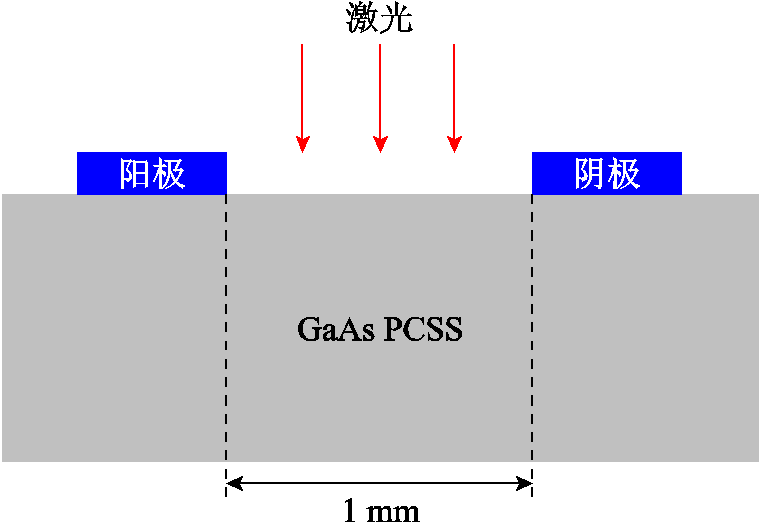
图1 GaAs PCSS的结构示意图
Fig.1 Structure diagram of GaAs PCSS
摘要 弱光触发下高倍增砷化镓光电导开关(GaAs PCSS)内以丝状电流为表现形式的载流子输运机制对其瞬态工作特性和寿命研究有重要意义。该文基于有限元方法构建了GaAs PCSS的物理模型,结合丝状电流的生热机制对1.5 μJ弱光触发下开关的瞬态输出电流和晶格温度进行了仿真分析,考察了偏置电场对GaAs PCSS输出特性的影响。通过不同时刻开关内部的瞬态电场、电子浓度和晶格温度等方面研究了高倍增模式下GaAs PCSS的光生载流子输运过程和损伤机理。结果表明,高密度丝状电流的存在伴随于高场畴的产生和发展。开关内部电场越高,负微分效应引起的载流子聚束现象越明显,相应的电子浓度和晶格温度值也越高;在浓度达1017 cm-3数量级的等离子体通道中,阳极附近电场强度和晶格温度最大值分别为220 kV/cm和821.92 K。
关键词:GaAs光电导开关 高倍增模式 丝状电流 输运机制
砷化镓光电导开关(Gallium Arsenide Photo-Conductive Semiconductor Switch, GaAs PCSS)是一种集激光技术和半导体技术于一体的超快光电器件,具有功率密度高、响应速度快、触发抖动低、抗电磁干扰能力强、体积小、易集成等优点,在兼顾输出电脉冲的重复频率和功率两方面有不可替代的优势[1-8]。GaAs PCSS有两种工作模式,分别是线性模式和高倍增模式[9-10]。相比于线性模式下每吸收一个光子产生一个电子-空穴对,高倍增模式下每吸收一个光子可产生103~105个电子-空穴对,所需光能要低3~5个数量级。因此,可以用激光二极管代替价格昂贵、体积庞大的固体激光器,实现脉冲功率系统的小型化[11-12]。然而,弱光触发下的高倍增GaAs PCSS导通过程中往往会伴随着高密度丝状电流的出现,从而产生大量焦耳热,而温度过高又会发生电流集中和电场畸变现象,最终导致开关的击穿[13-14]。因此,在弱光、强场的高倍增模式下对于GaAs PCSS瞬态特性的研究应该考虑生热过程的影响。开关内部的晶格温度与碰撞电离速率和电场强度相关,其分布可以预测热击穿发生的位置[15-18]。
目前通过调控GaAs PCSS内部丝状电流的产生和发展来提高其稳定性和寿命已经有一些报道。1990年,研究者通过红外猝灭的方法减小高倍增模式下波形锁定的时间,从而达到降低丝状电流对开关损伤的目的,但这种方法会增加光路系统的复杂性[19]。此外,设计视距透镜阵列和均匀光照屏蔽的PCSS能产生多条电流丝(约100条电流丝)[20],在欧姆接触之间增加n型掺杂层也可以在一定程度上缓解电流的聚集[21]。然而,对于引发丝状电流的光生载流子的产生、输运及成畴等内在物理过程和相关电热耦合效应还未见系统的研究报道。
本文针对高倍增模式下GaAs PCSS的瞬态输出特性和丝状电流导致的损伤问题,结合开关内部的生热过程建立电极间隙为1 mm的器件模型(与文献[22]中实验所用开关的间隙一致),考察弱光触发下偏置电场对GaAs PCSS输出特性的影响。在偏置电场强度为78 kV/cm条件下对不同时刻GaAs PCSS的瞬态特性进行研究,分析晶格温度影响下电场畸变与载流子的产生、输运及成畴等物理过程之间的关系。
电热耦合条件下GaAs PCSS的物理模型如图1所示。仿真中建立了一个尺寸为4 mm×0.6 mm、间隙为1 mm的共面GaAs PCSS,金属电极与半绝缘GaAs材料之间的接触为欧姆接触。整个开关主要被划分为三个区域,绿色区域为GaAs衬底,蓝色区域为电极(左侧为阳极,右侧为阴极),其余部分均为空气。考虑到电极附近高场和光吸收等关键区域,将网格设置为电极附近和开关表面网格密度高(网格参数为50 µm),纵向自上而下网格密度逐渐减小。在模拟中采用能量为1.5 μJ、脉宽为3.5 ns的弱光对GaAs PCSS进行触发。建模过程中考虑强场下载流子碰撞电离、复合以及晶格散射等多个物理过程,结合载流子的连续性方程和漂移-扩散方程来模拟GaAs PCSS的瞬态工作特性。

图1 GaAs PCSS的结构示意图
Fig.1 Structure diagram of GaAs PCSS
载流子连续性方程表示为
 (1)
(1)
 (2)
(2)
式中,n和p分别为电子和空穴浓度;q为单个电子的电荷量;Jn和Jp分别为电子和空穴电流密度;Gn和Gp分别为电子和空穴的碰撞电离速率;Rn和Rp分别为电子和空穴的复合速率。
考虑到高倍增模式下GaAs PCSS内电场和热场之间的耦合过程,漂移扩散方程增加了载流子温度相关项,表达式为
 (3)
(3)
 (4)
(4)
式中,μn和μp分别为电子和空穴的迁移率;En和Ep分别为电子和空穴漂移-扩散运动所形成电场的电场强度;Dn和Dp分别为电子和空穴的扩散系数,其与晶格温度TL相关;Tn和Tp分别为电子和空穴温度,热边界初始值设置为300 K。
GaAs材料具有三能谷的带隙结构,因此,高场下电子漂移速度与电场强度不再是简单的正比关系,而是随着电场强度增加呈非线性降低,并最终达到饱和。电子漂移速度与电场强度E的关系为
 (5)
(5)
空穴漂移速度与电场强度E的关系为
 (6)
(6)
式中,μn0为低场下电子迁移率,μn0=8 000 cm2/(V·s);μp0为低场下空穴迁移率,μp0=400 cm2/(V·s);vsn 和vsp分别为电子和空穴的饱和漂移速度,vsn= 7.7×106 cm/s,vsp=7.7×106 cm/s;Ec为负微分迁移率的阈值电场强度,Ec=4 kV/cm。
Okuto-Crowell碰撞电离模型具有温度相关系数,且适用的电场范围为105~106 V/cm[23],因此,在高倍增GaAs PCSS的建模过程中具有明显优势,其电离系数的表达式为
 (7)
(7)
 (8)
(8)
其中,An=0.426 V-1,Bn=3.05×10⁻⁴ K-1,Cn=4.81×10⁵ V/cm,Fn= 6.86×10⁻⁴ K-1,Ap=0.243 V-1,Bp=5.35×10⁻⁴ K-1,Cp= 6.53×10⁵ V/cm,Fp=5.67×10-4 K-1。
根据光电阈值条件,弱光(nJ~μJ)触发下GaAs PCSS进入高倍增模式时往往需要偏置更高的电场,这对开关的耐压能力、工作稳定性和寿命是一种挑战。GaAs材料在高场下存在负微分效应,因此,偏置电场的大小会对GaAs PCSS内部载流子的碰撞电离、复合及散射等过程产生影响,从而影响输出电流的幅值和器件内部温度的分布。下面在考虑开关内部生热机制条件下对触发光能为1.5 μJ、电极间隙为1 mm的GaAs PCSS进行高倍增瞬态特性研究,模拟不同偏置电场下的瞬态输出电流和晶格温度。
图2为光能为1.5 μJ,偏置电场强度分别为60、66、70、78 kV/cm时GaAs PCSS的输出电流波形。为直观对比不同偏置电场下PCSS瞬态输出电流的变化趋势,对其进行了归一化处理。可看到,仿真中当触发光能保持1.5 μJ,偏置电场强度从60 kV/cm增加到78 kV/cm时,对应输出电流波形均存在明显的拖尾(锁定现象),并且不同偏置电场下的锁定电流几乎为同一数值;此外,随着偏置电场强度的增大,输出电流幅值相应升高,上升时间相应减小。这些均与文献[22]中电极间隙为1 mm的GaAs PCSS在不同偏置电场下开关输出特性的分析一致。波形图中的锁定现象是GaAs PCSS工作在高倍增模式下的一个典型特征,这是由GaAs材料所特有的负微分效应决定的。当偏置电场增大时,GaAs PCSS内的负微分效应会更加明显,因此,载流子的碰撞电离速率也会相应增大,从而引起输出电流幅值的升高。
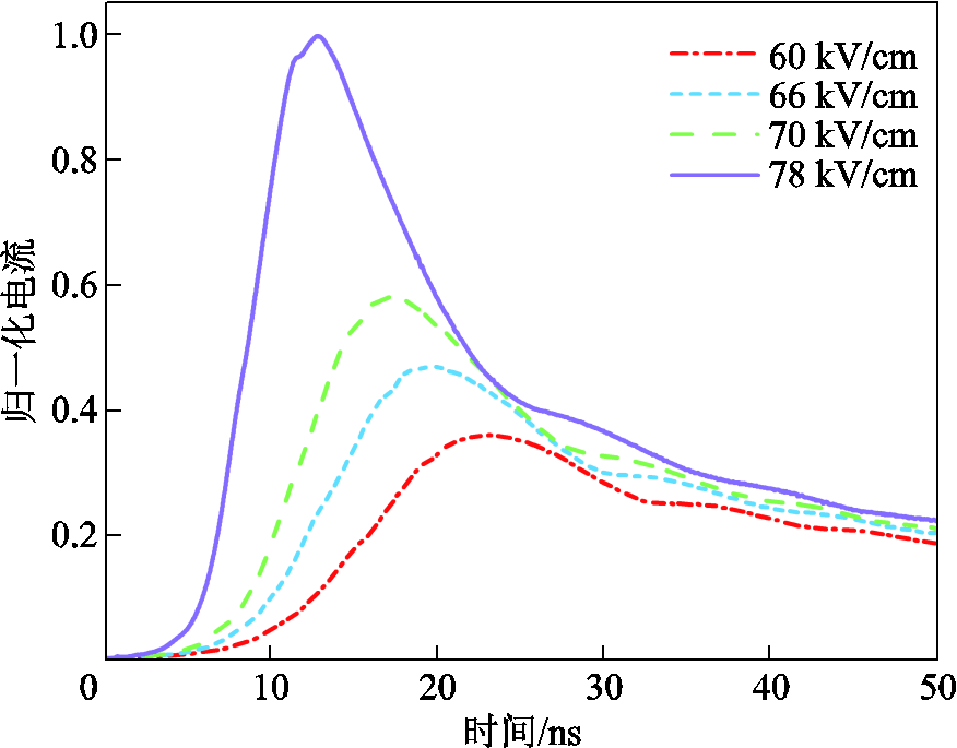
图2 光能为1.5 μJ、不同偏置电场下的输出电流
Fig.2 The output currents under 1.5 μJ excitation at different bias electric fields
高倍增模式下,GaAs PCSS内部丝状电流引发的热效应对其瞬态特性以及表面损伤问题研究具有重要意义。图3为光能为1.5 μJ,偏置电场强度分别为60、66、70、78 kV/cm时,GaAs PCSS的晶格温度峰值随时间的变化,仿真中热边界的初始值为室温300 K不变。
结合图2的电流波形,GaAs PCSS工作过程中器件内部晶格温度峰值随时间的变化分为三个阶段:电流上升阶段、电流下降阶段和电流锁定阶段。同时,与输出电流波形的变化趋势相比,晶格温度上升速率的变化会有滞后现象[17]。电流上升阶段,峰值温度随时间逐渐升高,同时偏置电场越高,峰值温度上升速率越快;电流下降阶段,不同偏置电场下的峰值温度上升缓慢,基本保持不变;电流锁定阶段,峰值温度也随时间呈逐渐上升的趋势,但其上升速率与偏置电场的大小无关。当偏置电场强度从60 kV/cm增加到78 kV/cm时,对应晶格温度的峰值分别为604.234、678.607、730.293 K和821.92 K。晶格温度的升高是由于载流子与晶格(电子-声子)之间发生散射使得载流子在受到强电场加速的同时将动能传递给晶格。因此,晶格温度的上升速率主要与开关内部电场强度的大小相关,电场强度越大,电子-声子散射越强,晶格温度上升速率越快。电流上升阶段,碰撞电离速率远大于复合速率,载流子数目急剧增长,并且电场强度越大会导致越多的载流子将能量传递给晶格,晶格温度上升越快;电流下降阶段,复合速率远大于碰撞电离速率,电子-声子散射的概率非常小,晶格温度几乎没有发生改变;电流锁定阶段,偏置电场的大小对锁定电压没有影响,因此,开关内部处于同一电场强度,晶格温度的上升速率也一致。
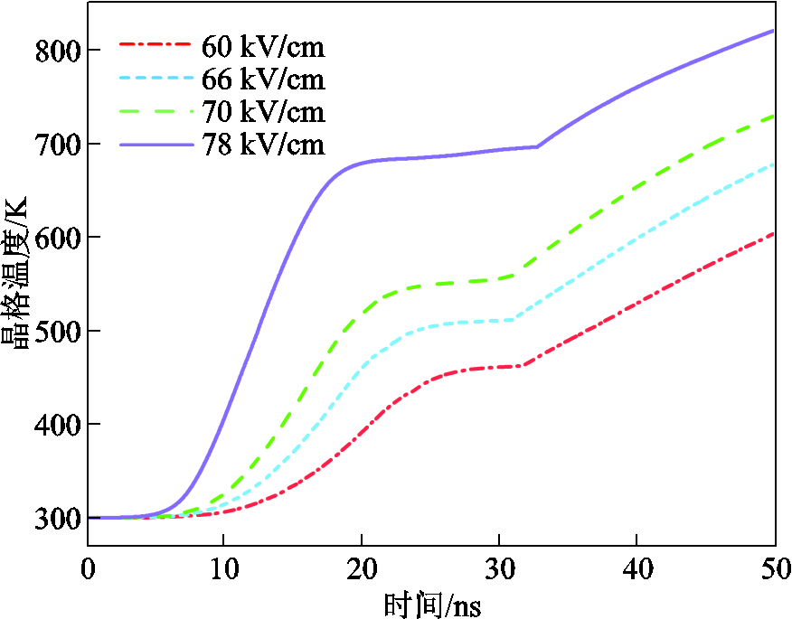
图3 光能为1.5 μJ、不同偏置电场下的晶格温度
Fig 3 The lattice temperatures under 1.5 μJ excitation at different bias electric fields
相比于线性模式,GaAs PCSS的高倍增模式能使所需触发光能降低3~5个数量级来实现脉冲功率系统的小型化,但其锁定现象通常会伴随着高密度丝状电流的产生,重复频率触发下连续的电流生热问题会对开关器件造成损伤。因此,载流子的聚束输运和丝状电流引发的热效应对GaAs PCSS的工作特性和寿命有显著影响。
在单次触发条件下,对触发光能为1.5 μJ、偏置电场强度为78 kV/cm时GaAs PCSS的高倍增特性进行仿真,研究其内部光生载流子的物理过程和热失效机制。图4为偏置电场强度为78 kV/cm、t=10 ns时刻GaAs PCSS的瞬态特性。如图4a所示,电场分布呈现中间低、电极两侧高的特点,阳极附近电场强度最大值为186 kV/cm,阴极附近电场强度最大值为229 kV/cm。这是由于光注入处会产生大量电子-空穴对,电场作用下电子和空穴分别向两极运动,形成一个与外加偏置电场反向的自建电场,从而导致开关内部电场分布的不均匀。图4b为y=0.48 mm处载流子浓度分布,由于GaAs材料在870 nm的光波长下吸收深度仅为几到几十微米,因此,相应的电子浓度分布于器件的表层区域。t=10 ns时刻光脉冲刚结束,部分光生载流子还未漂移到两极,电子和空穴浓度分布为中间高、电极两侧低。如图4c和图4d所示,碰撞电离和晶格散射过程主要发生在高场区域,因此,碰撞电离速率和晶格温度的值在开关表层的电极高场区域相对较高;同时,由于阴极是电子注入的位置,因此,阴极附近的碰撞电离速率和晶格温度大于阳极,碰撞电离速率和晶格温度的最大值分别为4.2×1025 cm-3∙s-1和408.79 K。
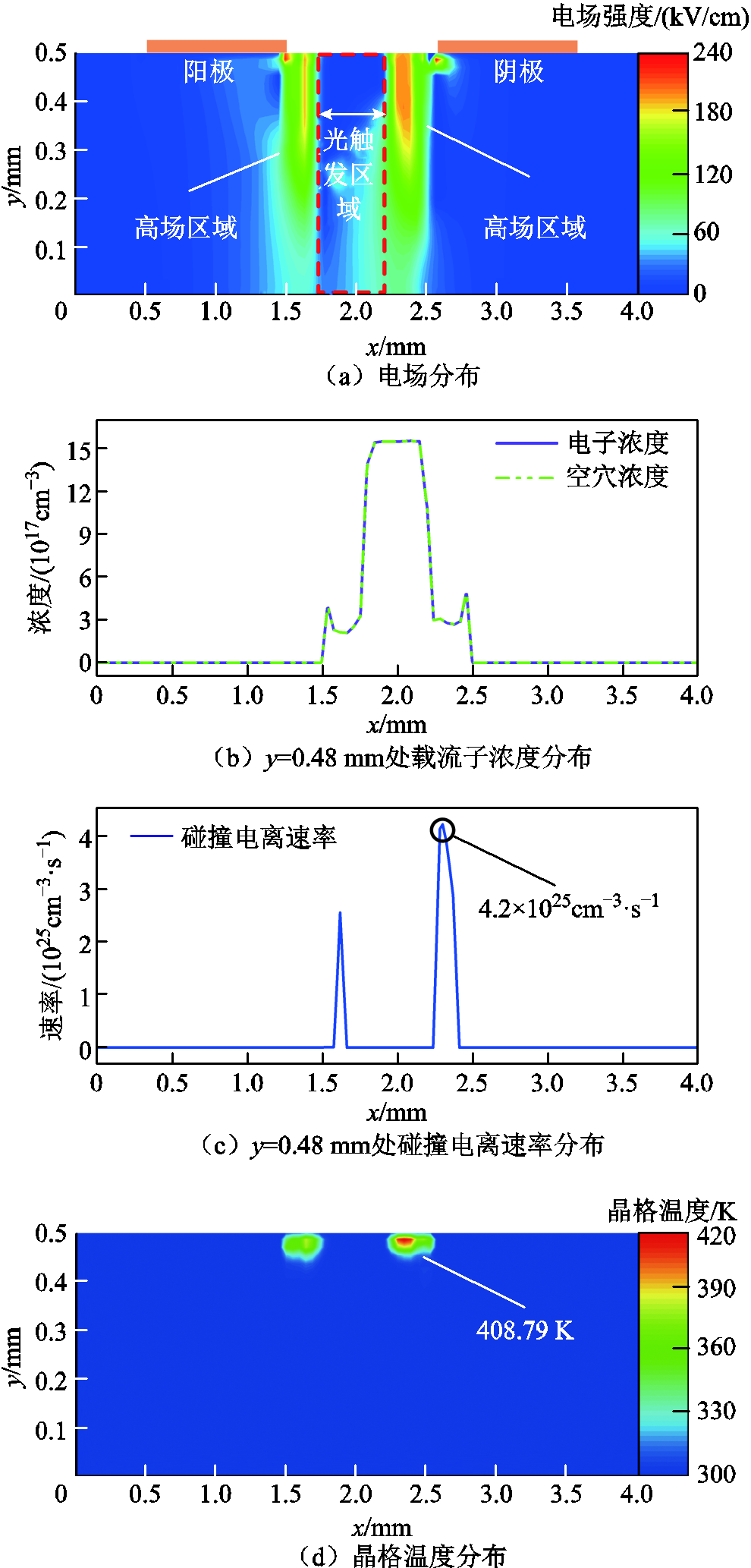
图4 偏置电场强度为78 kV/cm,t=10 ns时刻GaAs PCSS的瞬态特性
Fig.4 The transient characteristic of GaAs PCSS at t=10 ns and the bias electric field of 78 kV/cm
图5为偏置电场强度为78 kV/cm、t=50 ns时刻GaAs PCSS的瞬态特性。其中图5a和图5b分别是电场和载流子浓度分布,可见阳极附近为电场分布的高场区域,阴极附近仅有电极边缘处电场强度值较高。阳极附近电场强度最大值为220 kV/cm,阴极附近电场强度最大值为284 kV/cm,而电子和空穴浓度的分布为中间低、电极两侧高(约为1017 cm-3数量级)。与t=10 ns时刻相比,此时GaAs PCSS的负微分效应会使得电子在阳极附近发生聚束现象进而形成高场畴,畴内电场高于畴外电场,畴内载流子会发生剧烈的碰撞电离,载流子数目急剧增大。随着载流子浓度的升高,其复合效应相应增强,复合辐射的光成为新的触发光源,在开关内部产生新的高场畴,最终形成一条贯穿阴阳两极的丝状电流通道。图5c和图5d分别为t=50 ns时的碰撞电离速率和晶格温度分布。碰撞电离速率与电场强度、载流子浓度密切相关,阳极附近高场区域的碰撞电离速率远高于其他位置,其最大值为6.2×1022 cm-3∙s-1。晶格温度分布于开关表层丝状电流的位置,阳极附近晶格温度最大值为821.92 K,阴极附近晶格温度最大值为702 K(仍未达到GaAs熔点1 238℃[24])。

图5 偏置电场强度为78 kV/cm,t=50 ns时刻GaAs PCSS的瞬态特性
Fig.5 The transient characteristic of GaAs PCSS at t=50 ns and the bias electric field of 78 kV/cm
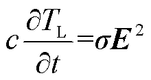
高倍增模式下开关内部载流子的输运过程和损伤机理与电场、电子浓度及晶格温度等物理量的分布和大小密切相关。为进一步探究高倍增模式下开关的热失效机制,基于热击穿方程的分析来研究电场、电子浓度和晶格温度之间的关系。由于表面损伤过程的瞬态和绝热性质,热击穿方程可以表示为
 (9)
(9)
式中,c为GaAs材料的比热容;σ为GaAs材料的电导率。等式左边是开关芯片温度上升所需的热量,右边表示开关内部电流所产生的焦耳热。电流密度σE可以表示为
 (10)
(10)
根据式(9)和式(10),GaAs PCSS的晶格温度增量 可以表示为
可以表示为
 (11)
(11)
式中,∆t为时间增量;ρ为GaAs材料的密度;V为GaAs PCSS体积。由式(11)可知电场强度E、电子浓度n与晶格温度增量∆TL三个物理量之间成正比关系。
在t=50 ns时刻,由GaAs PCSS内部微观物理量的瞬态分布可知,碰撞电离速率和载流子浓度较高处恰好对应着电场强度和晶格温度更高的位置,这与式(11)中分析的结论一致。实际应用中,虽然两电极处电流密度和载流子浓度的值在同一数量级,但是阳极接触处的退化和损坏比阴极处更严重。此时,开关阳极附近存在高场畴,畴内会发生雪崩碰撞电离产生大量电子-空穴对,因此,阳极附近有更多的电子将温度传递给晶格造成晶格热积累。晶格温度的分布决定着热击穿发生的位置,通过晶格温度分布可以判断热击穿产生在开关表面,并且电极(尤其是阳极)附近最为严重。
本文在考虑器件生热的条件下对1 mm间隙GaAs PCSS的高倍增瞬态特性进行了研究。当偏置电场强度从60 kV/cm增加到78 kV/cm时,GaAs PCSS输出电流和晶格温度的幅值相应升高。在偏置电场强度为78 kV/cm条件下,根据GaAs PCSS不同时刻的瞬态特性分析了开关内部的多个物理过程(载流子输运、电场畸变以及晶格生热等),揭示了电场、电子浓度及晶格温度三者之间的物理关系。结果表明,在t=50 ns时刻GaAs PCSS会形成一条载流子浓度达1017 cm-3数量级、贯穿阴阳两极的丝状电流通道,阳极附近晶格温度最高达821.92 K,阴极附近晶格温度最高达702 K。相关研究为弱光、重复频率工作条件下,高倍增模式GaAs PCSS内部载流子输运特性和损伤机理的研究提供了理论指导。
参考文献
[1] Majda-Zdancewicz E, Suproniuk M, Pawłowski M, et al. Current state of photoconductive semiconductor switch engineering[J]. Opto-Electronics Review, 2018, 26(2): 92-102.
[2] Ding Xiaofeng, Zhou Yang, Cheng Jiawei. A review of gallium nitride power device and its applications in motor drive[J]. CES Transactions on Electrical Machines and Systems, 2019, 3(1): 54-64.
[3] Xu Ming, Liu Chun, Luo Wei, et al. Pulse compression characteristics of an opposed-electrode nonlinear GaAs photoconductive semiconductor switch at 2 μJ excitation[J]. IEEE Electron Device Letters, 2022, 43(5): 753-756.
[4] Luan Chongbiao, Li Hongtao. Influence of hot-carriers on the on-state resistance in Si and GaAs photoconductive semiconductor switches working at long pulse width[J]. Chinese Physics Letters, 2020, 37(4): 044203.
[5] 袁建强, 刘宏伟, 马勋, 等. 基于光导开关的固态脉冲功率源及其应用[J]. 高电压技术, 2015, 41(6): 1807-1817. Yuan Jianqiang, Liu Hongwei, Ma Xun, et al. Development and application of solid state pulsed power generators based on photoconductive semi-conductor switches[J]. High Voltage Engineering, 2015, 41(6): 1807-1817.
[6] Ray S, Alla A, Naz S, et al. A method to maximize the amplitude of generated terahertz pulse from LT GaAs photoconductive semiconductor switch[J]. IEEE Trans-actions on Plasma Science, 2015, 43(6): 1851-1854.
[7] 高荣荣, 徐鸣, 罗伟, 等. 重复频率下GaAs光电导开关的热积累研究[J]. 电工技术学报, 2023, 38(15): 4010-4018. Gao Rongrong, Xu Ming, Luowei, et al. Research on thermal accumulation of GaAs photoconductive switch at repetition rates[J]. Transactions of China Electrotechnical Society, 2023, 38(15): 4010-4018.
[8] Nunnally W C. Critical component requirements for compact pulse power system architectures[J]. IEEE Transactions on Plasma Science, 2005, 33(4): 1262-1267.
[9] Wang Langning, Liu Jingliang. Solid-state nanosecond pulse generator using photoconductive semiconductor switch and helical pulse forming line[J]. IEEE Transactions on Plasma Science, 2017, 45(12): 3240-3245.
[10] 谌怡, 刘毅, 王卫, 等. 激光二极管触发GaAs光导开关导通特性[J]. 高电压技术, 2019, 45(1): 310-315. Shen Yi, Liu Yi, Wang Wei, et al. On-state properties of GaAs photoconductive semiconductor switch triggered by laser diode[J]. High Voltage Engineering, 2019, 45(1): 310-315.
[11] Chowdhury A R, Ness R, Joshi R P. Assessing lock-on physics in semi-insulating GaAs and InP photoconductive switches triggered by subbandgap excitation[J]. IEEE Transactions on Electron Devices, 2018, 65(9): 3922-3929.
[12] Hu Long, Su Jiancang, Qiu Ruicheng, et al. Failure mechanism of a low-energy-triggered bulk gallium arsenide avalanche semiconductor switch: simulated analysis and experimental results[J]. IEEE Transactions on Electron Devices, 2018, 65(9): 3855-3861.
[13] 刘向向, 李志刚, 姚芳. 不同工作模式下的IGBT模块瞬态热特性退化分析[J]. 电工技术学报, 2019, 34(增刊2): 509-517. Liu Xiangxiang, Li Zhigang, Yao Fang. Degradation analysis of transient thermal characteristics of IGBT module under different working conditions[J]. Transactions of China Electrotechnical Society, 2019, 34(S2): 509-517.
[14] Chu Xu, Xun Tao, Wang Langning, et al. Breakdown behavior of GaAs PCSS with a backside-light-triggered coplanar electrode structure[J]. Electronics, 2021, 10(3): 357.
[15] 吕安强, 李静, 张振鹏, 等. 夹具对高压绝缘电缆热学特性影响的有限元分析[J]. 电工技术学报, 2022, 37(1): 283-290. Lü Anqiang, Li Jing, Zhang Zhenpeng, et al. Finite element analysis for the influence of clamp on the thermal characteristics of high voltage insulated power cable[J]. Transactions of China Electrotechnical Society, 2022, 37(1): 283-290.
[16] 陈宇, 周宇, 罗皓泽, 等. 计及芯片导通压降温变效应的功率模块三维温度场解析建模方法[J]. 电工技术学报, 2021, 36(12): 2459-2470. Chen Yu, Zhou Yu, Luo Haoze, et al. Analytical 3D temperature field model for power module considering temperature effect of semiconductor voltage drop[J]. Transactions of China Electrotechnical Society, 2021, 36(12): 2459-2470.
[17] Sun Yue, Hu Long, Li Yongdong, et al. Research on the thermal failure mechanism of an opposed-contact gallium arsenide photoconductive semiconductor switch in avalanche mode[J]. Journal of Physics D: Applied Physics, 2022, 55(21): 215103.
[18] 魏艳慧, 郑元浩, 龙海泳, 等. 绝缘层厚度对高压直流电缆电场和温度场分布的影响[J]. 电工技术学报, 2022, 37(15): 3932-3940. Wei Yanhui, Zheng Yuanhao, Long Haiyong, et al. Influence of insulation layer thickness on electric field and temperature field of HVDC cable[J]. Transactions of China Electrotechnical Society, 2022, 37(15): 3932-3940.
[19] Mazzola M S, Schoenbach K H, Lakdawala V K, et al. Infrared quenching of conductivity at high electric fields in a bulk, copper-compensated, optically activated GaAs switch[J]. IEEE Transactions on Electron Devices, 1990, 37(12): 2499-2505.
[20] Zutavern F J, Glover S F, Mar A, et al. High Current, multi-filament photoconductive semiconductor switching [C]// 2011 IEEE Pulsed Power Conference, Chicago, IL, USA, 2012: 1112-1119.
[21] Zhu K, Doğan S, Moon Y T, et al. Effect of n+-GaN subcontact layer on 4H–SiC high-power photoconductive switch[J]. Applied Physics Letters, 2005, 86(26): 261108.
[22] Xu Ming, Dong Hangtian, Liu Chun, et al. Investigation of an opposed-contact GaAs photoconductive semiconductor switch at 1-kHz excitation[J]. IEEE Transactions on Electron Devices, 2021, 68(5): 2355-2359.
[23] Okuto Y, Crowell C R. Threshold energy effect on avalanche breakdown voltage in semiconductor junctions[J]. Solid-State Electronics, 1975, 18(2): 161-168.
[24] Ma Cheng, Yang Lei, Dong Chengang, et al. An experimental study on LT-GaAs photoconductive antenna breakdown mechanism[J]. IEEE Transactions on Electron Devices, 2018, 65(3): 1043-1047.
Abstract Gallium arsenide photoconductive semiconductor switch (GaAs PCSS) is one of the most promising solid-state switches with a simple structure, fast response time, low jitter, strong optical trigger isolation, and easy integration, which has a wide range of applications in terahertz technology, ultra-fast pulse sources, and high power microwave. GaAs PCSS has two operating modes: linear and high gain (HG). However, the conduction process of the HG GaAs PCSS is often accompanied by the high-density filamentary current under low optical energy (nJ-µJ), which generates a lot of Joule heat to damage device. In this paper, a two-dimensional (2D) electrothermal coupling model of GaAs PCSS is set up based on the self-heating effect, and the transient characteristics of the switch are investigated at the optical excitation of 1.5 µJ.
Firstly, the output currents of HG GaAs PCSS under different bias electric fields are investigated. The results show that the corresponding output current waveforms have obvious trailing (lock-on), and the locking currents are almost the same at the optical excitation of 1.5 µJ as the bias electric field increases from 60 kV/cm to 78 kV/cm. In addition, the output current amplitude increases and the rise time decreases accordingly with the increase of the bias electric field.
Secondly, the lattice temperatures of HG GaAs PCSS are investigated under different bias electric fields, considering the influence of the thermal field on the stability and physical process of the device. The results show that the rise of lattice temperature over time is divided into three stages combined with the current waveform, namely, the current rising stage, current descending stage and current lock-on stage. The rise rate of lattice temperature is determined by the bias electric field and the rise stage. The lattice temperature increases with the increase of the bias electric field, and the maximum lattice temperature can reach 821.92 K at the bias electric field of 78 kV/cm.
Finally, the carrier transport process and thermal failure mechanism inside the switch are investigated by the distribution of the electric field, carrier concentration, impact ionization rate, and lattice temperature under single shot conditions. At t =10 ns, the high-field regions of the electric field, impact ionization rate, and lattice temperature are located near the electrodes. The values near the cathode are the maximum due to electron injection, which are 229 kV/cm, 4.2×1025 cm-3∙s-1, and 408.79 K, respectively. At t=50 ns, the filamentary current with a carrier concentration of 1017cm-3 is formed on the surface of GaAs PCSS through the anode and the cathode. The high-field regions of electric field, impact ionization rate, and lattice temperature are located near the anode, where the maximum values are 220 kV/cm, 6.2×1022 cm-3∙s-1, and 821.92 K, respectively. The relationship between the electric field, impact ionization rate, and lattice temperature is proven, which provides the possibility to predict the position of thermal breakdown.
The relevant research providesthe theoretical guidance for the study of carrier transport characteristic and damage mechanism of HG GaAs PCSS under the condition of high repetition rate.
keywords:GaAs photoconductive semiconductor switch, high-gain mode, filamentary current, transport mechanism
DOI:10.19595/j.cnki.1000-6753.tces.230198
中图分类号:O473;TM564
国家自然科学基金项目(52277164, 51877177)、陕西高校青年创新团队项目(超快光电器件与材料)、陕西省科技计划重点项目(2021JZ-48)和陕西省教育厅青年创新团队建设项目(21JP085, 21JP088, 22JP058)资助。
收稿日期 2023-02-21
改稿日期 2023-04-30
司鑫阳 女,1998年生,硕士研究生,研究方向为超快光电导器件机理分析。E-mail: 1421938064@qq.com
徐 鸣 男,1979年生,教授,博士生导师,研究方向超快光电导器件及其应用。Email: xuming@xaut.edu.cn(通信作者)
(编辑 李 冰)