
图1 膝关节正交接收线圈支撑结构示意图
Fig.1 Diagram of the quadrature receive coil support structure for the knee joint
摘要 射频接收线圈是磁共振成像(MRI)系统中的关键部件,用于检测变化的磁场,其性能直接影响图像的质量。超低场MRI射频接收线圈工作在较低频率,其阻抗特性不同于传统临床MRI射频接收线圈。理论上正交接收线圈比单通道线圈的信噪比(SNR)可以提高41%。而与阵列线圈相比,正交接收线圈可以用更低的成本与设计复杂度达到很好的成像效果。因此该文研究了一种用于超低场MRI(50.4 mT)系统的膝关节正交接收线圈,它由鞍形线圈和亥姆霍兹线圈组成。首先,确定了线圈的支撑结构及尺寸,并通过计算单匝接收线圈的效率及磁场的不均匀性来确定鞍形以及亥姆霍兹线圈的最优尺寸。然后,实测了线圈交流电阻,来评估线圈不同匝数的SNR,发现匝数增多会使得交流电阻显著增加,从而使SNR随着线圈匝数增加先增加后减少。最后,得到了两线圈的最佳匝数,并制作了正交接收线圈,从CuSO4∙5H2O体膜以及体内膝关节成像来评估正交接收线圈的性能。在体膜和体内膝关节成像中,正交接收线圈与单通道线圈相比,图像SNR分别最大程度地提升了约33.5%和30.9%。
关键词:磁共振成像 超低场 膝关节成像 正交接收线圈
磁共振成像(Magnetic Resonance Imaging, MRI)在科学研究和临床诊断中发挥着不可替代作用[1-3]。超低场(Ultra-Low-Field, ULF)MRI由于信噪比(Signal-to-Noise Ratio, SNR)低,一直被行业忽视。近年来,随着硬件、图像去噪[4]、脉冲序列[5]等方面的发展,ULF-MRI正在重新成为国内外学者们的研究焦点[6-12]。相比于中、高场MRI系统(1.0 T磁感应强度及以上),ULF-MRI设备(0.1 T磁感应强度以下)具有低成本、不受使用场地限制等优点,在床旁监护、移动脑卒中单元等应用场合受到了广泛关注。
ULF-MRI通过降低背景磁场来降低成像系统的复杂度、减小系统的重量和体积,实现MRI系统轻量化、可移动的特点,并搭配高性能的外围谱仪,功放及梯度、射频线圈等实现可靠的成像效果。2015年,美国哈佛医学院的Matthew Rosen团队研制出6.5 mT的ULF-MRI系统[6]。2019年,本研究团队开发出50 mT ULF-MRI系统[7],结合屏蔽房实现脑卒中诊断,并实现对一位出血性脑卒中患者17天的长期监测成像。2020年,莱顿大学医学中心的T.O′Reilly研究了一种采用Halbach磁体的ULF-MRI系统[8],其成像孔直径为27 cm,离散化 Halbach 永磁阵列实现了50 mT的主磁感应强度。2020年2月,美国Hyperfine公司推出了首款商用可移动64 mT ULF-MRI系统并通过美国FDA认证,该系统高度约为1.5 m,重量约为650 kg。该设备结合噪声消除技术可在无屏蔽的开放环境下运行,实现可观的图像SNR并应用于感染新型冠状病毒(COVID-19)病人的床旁监护[9-10],但受商业保密限制,其相关技术细节未见发表。
本文专注于ULF-MRI系统的射频接收线圈。射频接收线圈[13]根据通道数可分为单通道线圈[14-17]、正交线圈[18-23]和阵列线圈[24-26]。单通道线圈包括螺线管、鞍形线圈、亥姆霍兹线圈以及其他经典结构线圈,结构和设计简单。然而,单通道线圈很容易得到改进,通过增加另一个垂直于单通道的线圈,可以有效地提高图像SNR[27-29]。类似于雷达阵列,阵列线圈由多个单通道线圈组成。多通道线圈可以明显地提高SNR,是目前研究最热的线圈结构,因为它可以提供具有大视场的高SNR图像,并可用于并行成像以减少成像时间[30-31]。但是,阵列线圈设计和结构复杂,需要经验非常丰富的设计员进行设计,并且其成本高。总的来说,正交线圈在硬件成本和性能之间取得了很好的平衡,目前仍广泛用于临床以及实验研究中[21, 28]。因此,该文打算开发一种用于ULF-MRI的膝关节正交接收线圈。
临床MRI中的射频接收线圈已经得到了高速发展[32-33],而ULF-MRI工作在较低频率,使得线圈的阻抗特性存在差异,意味着最佳的接收线圈不同。因此,本文从线圈匝数的角度研究了ULF-MRI线圈的性能,揭示了线圈效率(由单位电流产生的平均射频磁场定义)和电阻随线圈匝数变化的变化速率不同。这说明线圈的匝数会影响线圈的交流电阻,并显著影响线圈的SNR。最后本文获得了最佳膝关节正交接收线圈参数并制作了实物,实现了体膜(填充CuSO4∙5H2O)和体内膝关节成像。本文计算了MR图像的SNR,发现正交接收线圈的图像SNR与单通道线圈相比得到了显著提升。
在本工作中,要优化的正交接收线圈由鞍形和亥姆霍兹线圈组成。首先确定单匝鞍形和亥姆霍兹线圈的尺寸,然后通过评估SNR得到两线圈的最佳匝数,最后用调谐和匹配电路对其进行匹配,得到最佳正交接收线圈样机。
本文设计的射频正交接收线圈用于膝关节MRI。为适应膝关节尺寸,并提高填充因子,设计了一款半径为80 mm、长度为200 mm的线圈支撑结构,如图1a所示。同时提高线圈的实用性,本文将圆柱形设计为开合结构,如图1b所示,红色区域为感兴趣区域(Region of Interest, ROI),其半径为65 mm,长度为100 mm。
图1 膝关节正交接收线圈支撑结构示意图
Fig.1 Diagram of the quadrature receive coil support structure for the knee joint
本文采用鞍形与亥姆霍兹线圈构成正交接收线圈,如图2所示。为了获得鞍形与亥姆霍兹线圈的最佳尺寸参数,本文计算了ROI内的线圈效率以及射频磁场不均匀性,分析两者之间的关系,最终获得了一组考虑尺寸约束、线圈效率和射频磁场不均匀性之间权衡的最佳尺寸参数。
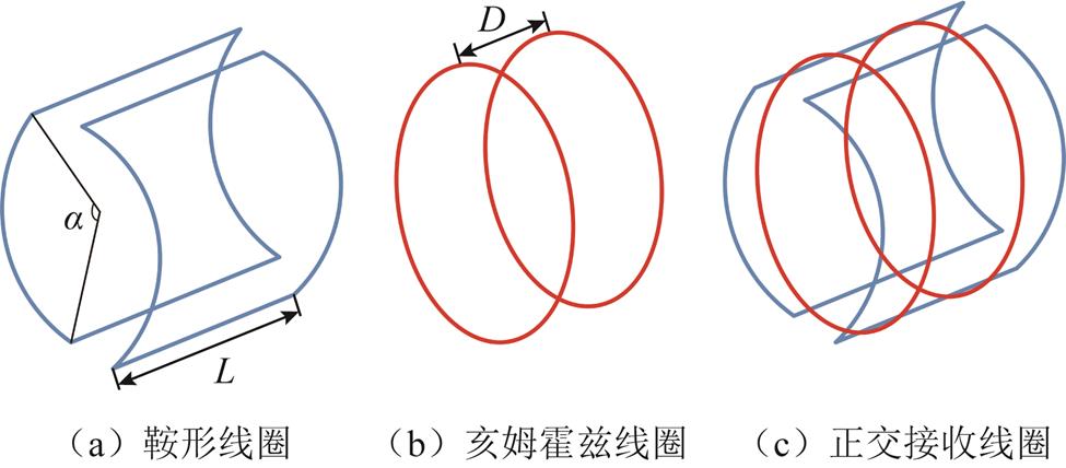
图2 膝关节正交接收线圈组成及优化参数
Fig.2 Composition and optimization parameters of the knee quadrature receive coil
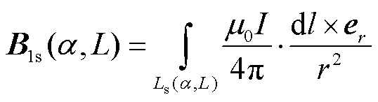
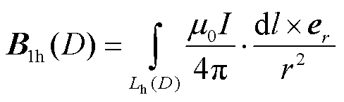
鞍形线圈的结构参数由角度α和长度L(见图2a)决定,亥姆霍兹线圈的结构参数由两个环之间的间隙D(见图2b)决定。考虑到线圈工作磁感应强度很低(50.4 mT),因此线圈的尺寸远小于电磁波的长度。本文使用毕奥-萨伐尔定律直接计算接收线圈的磁场。ROI的磁场分别由鞍形与亥姆霍兹线圈贡献,其磁场分别表示为B1s和B1h,计算式为
 (1)
(1)
 (2)
(2)
式中, 为真空磁导率;Ls为鞍形线圈的绕组路径;r为导线到ROI中目标点的距离;I为接收线圈的激励电流;er为从接收线圈指向ROI中的目标点的单位矢量;Lh为亥姆霍兹线圈的绕组路径。
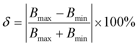
正交接收线圈的性能由射频磁场不均匀性和SNR决定。射频磁场的不均匀性δ由式(3)量化,即射频磁场在ROI内的最大相对误差。同时,接收线圈的SNR由式(4)进行评估[34]。在优化过程中,以降低射频磁场的不均匀性、同时提高接收线圈的SNR为目标[16]。
 (3)
(3)
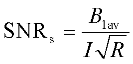 (4)
(4)
式中,Bmax和Bmin分别为射频磁场磁感应强度分量的最大值与最小值,垂直于静态磁场(B0)方向;B1av为ROI磁场的平均值;R为接收线圈的交流电阻。
本文通过计算不同结构参数下线圈的效率和单匝鞍形线圈的不均匀性,初步优化鞍形线圈的结构。具体步骤:将α的范围设置为2°~180°,步长为2°;L设置为2~200 mm,步长为2 mm。总共计算了9 000组数据,获得了磁场不均匀性与单匝线圈效率之间的关系,如图3所示。从图3中可以发现,鞍形线圈的不均匀性基本随线圈效率的升高而降低。最后,该文确定了效率为7.8 μT/A、不均匀性为24.7%的工作点,对应于α=120°和L=180 mm的结构参数。
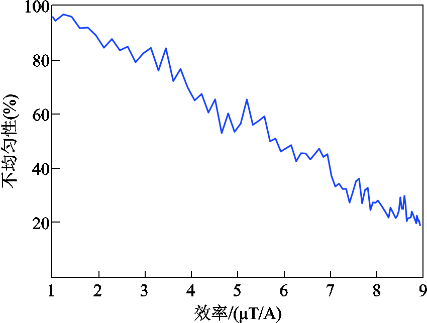
图3 磁场不均匀性和鞍形线圈效率之间的关系
Fig.3 Relationship between saddle coil efficiency and magnetic field inhomogeneity
同样地,本文也计算了亥姆霍兹线圈的效率与磁场的不均匀性,具体地,将D的范围设置为2~200 mm,步长为2 mm。磁场不均匀性与单匝亥姆霍兹线圈效率之间的关系如图4所示。其中随着效率提升,射频磁场的不均匀性先降低,后增加。由于效率低,本工作拒绝了射频磁场不均匀性最小的工作点。最后确定了效率和射频磁场不均匀性平衡的工作点,选取了效率为13.4 μT/A、不均匀性为19.3%的工作点,对应于D=54 mm的结构参数。
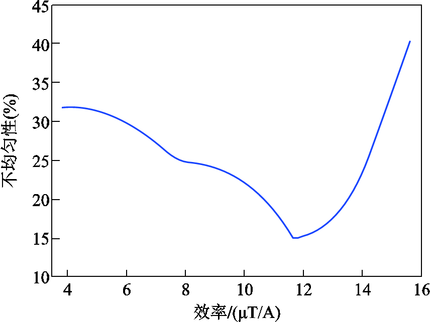
图4 磁场不均匀和亥姆霍兹线圈效率性之间的关系
Fig.4 Relationship between Helmholtz coil efficiency and magnetic field inhomogeneity
通过尺寸优化后,该文初步确定了单匝射频接收线圈的最佳结构。由式(4)可知,射频接收线圈的SNR主要由线圈效率和交流电阻决定。对于已知尺寸的射频接收线圈,本文通过调整射频接收线圈匝数来改变其效率和交流电阻,同时,对磁场不均匀性没有显著影响。随着线圈匝数的变化,射频接收线圈的效率和交流电阻变化趋势不同,意味着可以通过改变线圈匝数来优化射频接收线圈的SNR。
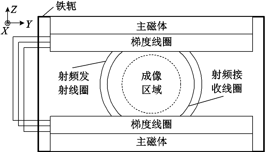
图5 永磁体MRI系统结构
Fig.5 Structure of permanent-magnet MRI system
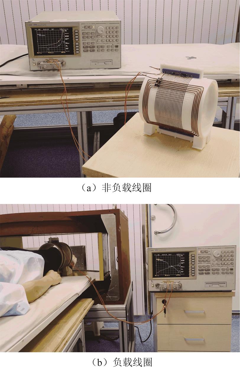
图6 射频接收线圈交流电阻测量
Fig.6 AC resistance measurement of the RF receive coil
本文计算了正交接收线圈的每个单通道线圈的SNR。根据式(4),计算SNR时需要得到射频线圈效率和交流电阻。通过式(1)、式(2)可以有效地计算不同匝数的射频线圈效率。然而射频线圈的交流电阻受多个因素的影响,很难用解析表达式或特定的仿真模型得到。
在本项研究中,射频接收线圈在MRI扫描仪中工作,该扫描仪由铁轭、永磁体、防涡流板、梯度线圈系统和射频发射线圈组成(见图5)。MRI扫描仪的这些组件和待扫描患者通过改变周围的磁导率、电导率等增加了射频接收线圈的交流电阻。于是本文将射频接收线圈置于实际的工作环境中,使用阻抗分析仪(安捷伦,4294A,美国)进行测量,测量了不同匝数的射频接收线圈的交流电阻,其中,Runloaded表示在工作台上射频接收线圈的交流电阻(图见6a),Rloaded表示在工作状态下射频接收线圈的交流电阻(见图6b)。具体来讲,本文分别测量了鞍形和亥姆霍兹线圈匝数为1~11匝的交流电阻,并测量了空载以及负载情况下的电阻值,通过式(4)计算了SNR,并对SNR进行了归一化处理。鞍形和亥姆霍兹线圈的测量参数和归一化SNR分别见表1和表2。
表1 鞍形线圈参数
Tab.1 Parameters of saddle coil

线圈匝数1357911 B1av/(μT/A)7.62236.852.567.979.3 Runloaded/Ω0.71.33.27.514.839.6 Rloaded/Ω0.81.74.612.436.860.7 归一化SNR0.490.9810.870.650.6
表2 亥姆霍兹线圈参数
Tab.2 Parameters of Helmholtz coil
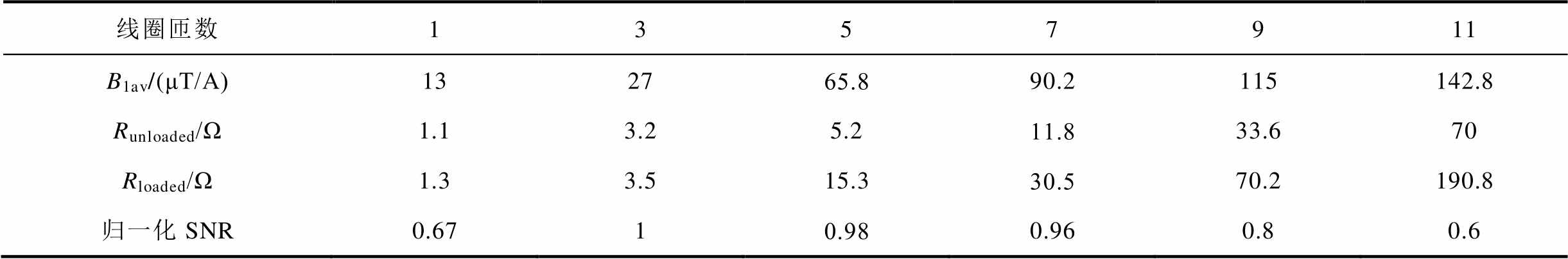
线圈匝数1357911 B1av/(μT/A)132765.890.2115142.8 Runloaded/Ω1.13.25.211.833.670 Rloaded/Ω1.33.515.330.570.2190.8 归一化SNR0.6710.980.960.80.6
由表1和表2所示的磁场计算(B1av)结果可知,鞍形以及亥姆霍兹线圈的效率基本上随匝数增加而线性增加。由表1和表2所示的电阻测量(Runloaded, Rloaded)结果可知,射频线圈的负载和空载交流电阻值随着匝数的增加而增加,且线圈匝数越多电阻上升得越快。同时,负载交流电阻大于空载交流电阻。射频线圈的SNR随着匝数的增加先增加,然后降低,表明鞍形和亥姆霍兹线圈的最佳匝数分别在5匝和3匝左右。进一步地,本文分析了线圈匝数为2、4和6的射频线圈的参数,线圈归一化SNR和匝数关系如图7所示。

图7 鞍形和亥姆霍兹线圈归一化SNR与线圈匝数的关系
Fig.7 Relationship between normalized SNR of saddle and Helmholtz coils and coil turns
根据图7所示的结果,最终,本文确定鞍形和亥姆霍兹线圈的最佳匝数分别为5匝和4匝。
经过上述设计,本文得到了正交接收线圈的最佳尺寸参数和最佳线圈匝数。在实际射频电路中,为了最大可能地检测到MR信号,阻抗匹配是非常重要的手段。于是,本文使用了传统的π形电路对正交接收线圈的两个单通道接收线圈进行调谐和匹配,如图8a所示,其中Rc和Lc为线圈的等效电阻和电感,线圈阻抗匹配主要通过调节Ct、Cm实现。线圈匹配中采用的电容为无磁电容(DLC75, 大连达利凯普科技股份公司, 中国)。在调谐和匹配后,为了改善两个通道之间的正交隔离,本文在两通道之间插入了一个低值可变的电容[35]。然后,使用Rohde&Schwarz公司的ZND矢量网络分析仪测量了两线圈的回波损耗参数S11以及隔离度参数S12。亥姆霍兹和鞍形线圈的S11分别为-20.2 dB和-23.1 dB,隔离度S12小于-15.3 dB。最终,最佳正交接收线圈样机如图8b所示。
本实验研究经西南医院伦理委员会批准。获得成像受试者和健康志愿者的知情同意。MRI成像是根据批准的指南和规定进行的。

图8 正交接收线圈调谐和匹配电路及样机
Fig.8 The quadrature receive coil tuning and matching circuit and prototype
本文使用最佳正交接收线圈,首先实现了圆柱体体膜成像。圆柱体体膜由CuSO4∙5H2O溶液(1.95 mg/mL,见图9a和图9b)填充。ULF-MRI扫描仪的射频发射线圈如图9c所示。本文使用梯度回波(GRE3D)序列扫描体模,体素矩阵为176×128×20,体素尺寸为2 mm×1.4 mm×10 mm,翻转角度为35°,平均数为1。在2 min内获得体膜成像结果如图10所示。
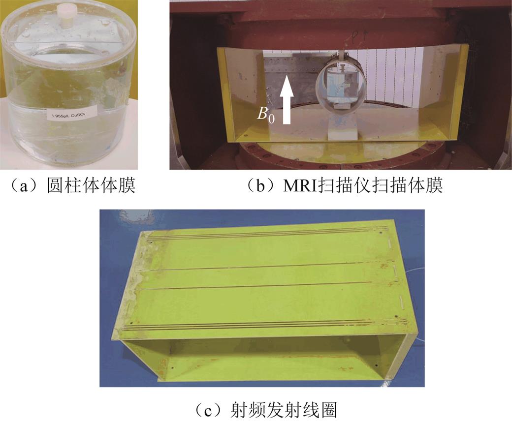
图9 体膜成像
Fig.9 Phantom imaging
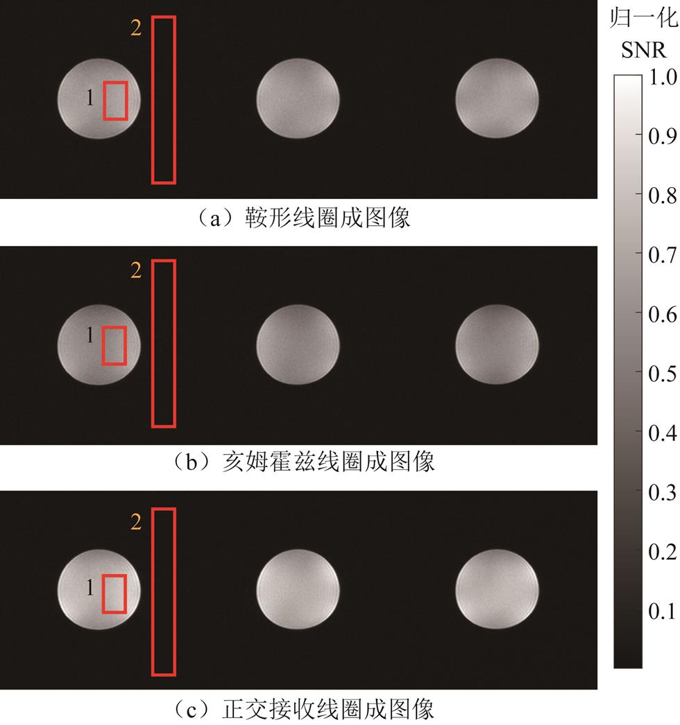
图10 体膜成像结果
Fig.10 Imaging results of the phantom
在图10中,通过求解由鞍形和亥姆霍兹线圈得到的图像像素值二次方和的二次方根来得到正交接收线圈的图像。本文计算了如图10所示的红框1中的图像SNR,红框2表示噪声像素区域。每个单通道都在相同位置进行图像SNR的计算。图像SNR定义为图像中心的平均像素值与噪声像素值的标准偏差之比。其中正交接收、鞍形和亥姆霍兹线圈的图像SNR分别为63.8、48、47.8。因此,在体膜成像中,正交接收线圈图像SNR比单通道接收线圈SNR最多可提高约33.5%。
在完成体膜成像后,本文使用分辨率矩阵为176×128×40,分辨率尺寸为2 mm×1.4 mm×5 mm,翻转角度为35°,平均数为1的GRE3D序列扫描健康志愿者的膝关节。在4 min内获得成像结果(T1加权膝关节图像)如图11所示。同样地,本文利用红框2中的噪声像素区域,计算了红框1中的图像SNR。正交接收、鞍形和亥姆霍兹线圈的图像SNR分别为27.1、21.6、20.7。
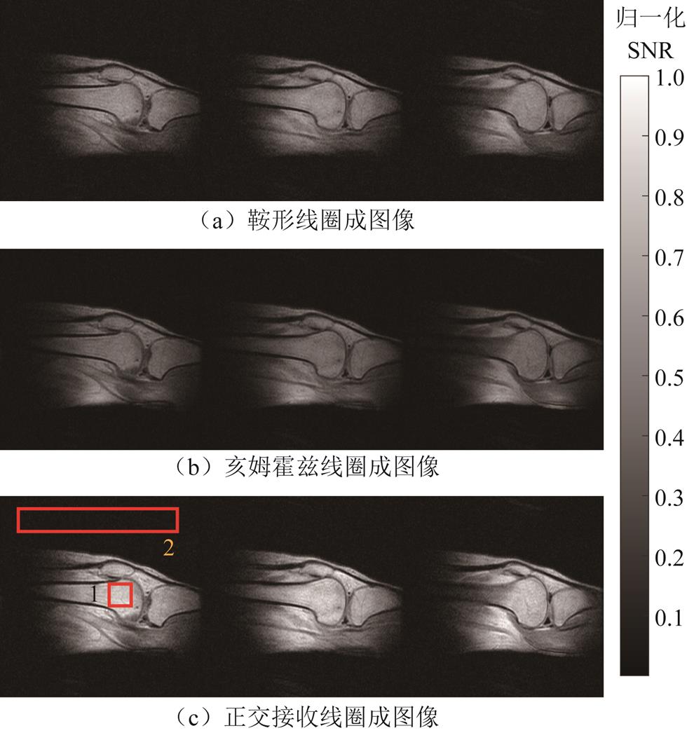
图11 使用GRE3D序列获得的膝关节图像(矢状面)
Fig.11 Knee images obtained using the GRE 3D sequence (sagittal plane)
本文还使用分辨率矩阵为176×120、体素尺寸为1.4 mm×2.1 mm×10 mm、翻转角度为90°,平均数量为4的快速自旋回波(Fast Spin Echo, FSE)序列扫描健康志愿者的膝关节。在8 min 30 s内获得成像结果(T2加权膝关节图像)如图12所示。通过计算,本文得到了红框1中的图像SNR。正交接收、鞍形和亥姆霍兹线圈的图像SNR分别为24.3、20.8、19。在体内膝关节成像中,正交接收线圈图像SNR比单通道接收线圈SNR最多可提高约30.9%。
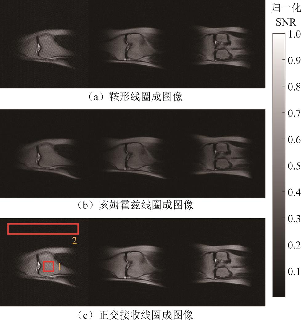
图12 使用FSE序列获得的膝关节图像(冠状面)
Fig.12 Knee images obtained using the FSE sequence (coronal plane)
在本文的工作中,最初认为接收线圈匝数越多,图像SNR会越高[16],但是,在实际中线圈匝数越高,交流电阻会呈指数增加,使得SNR先升高后下降。同时,目前对交流电阻的数值计算仍然不准[36],不得不对线圈电阻进行实测,这使得设计过程更加繁琐。在实际测量电阻时,本文通过阻抗分析仪进行测量,甚至得到了负交流电阻,这可能与阻抗分析仪测量类型(不能测量感性负载的阻抗)有关。最后,本文使用电容与线圈串联,使其在MRI扫描仪的拉莫尔频率下发生串联谐振以测得线圈的交流电阻。在未来的优化设计中,需要解决交流电阻计算不准的问题,为后续线圈设计工作提高时效性奠定基础。
本文利用最佳的正交接收线圈完成了体膜和体内膝关节成像,与体膜图像SNR相比,体内膝关节图像SNR明显降低,这是因为人体进入线圈后,线圈的交流电阻增加,同时,人体也会耦合环境噪声。
本文使用开合结构的膝关节线圈以满足不同人群膝关节的尺寸。亥姆霍兹线圈与接口一端焊接,接口的另一端实现开合,本文实际连接的匝数为4匝。在测量中发现接口处会引入额外的电阻,这对SNR参数来说是一个不好的设计,但本文的实验结果表明,开合结构的正交接收线圈是成功的。在后续的工作中,仍然需要改进接口方式,以减小接口处引入的电阻。
本文设计并制造了一种用于ULF-MRI的膝关节正交接收线圈,该线圈由鞍形和亥姆霍兹线圈组成。最后,使用该正交接收线圈实现了体模和体内膝关节成像,与单通道接收线圈相比,图像SNR都得到了明显提高。在这项工作中,从射频接收线圈匝数的角度对线圈进行了分析和优化,揭示了线圈匝数是影响ULF-MRI(50.4 mT)射频接收线圈SNR的重要因素,为射频接收线圈的设计和优化提供了新的依据。
参考文献
[1] 李晓南, 任雯廷, 刘国强, 等. 高分辨率磁共振电特性成像及脑肿瘤诊断初步研究[J]. 电工技术学报, 2021, 36(18): 3860-3866. Li Xiaonan, Ren Wenting, Liu Guoqiang, et al. Preliminary conductivity reconstruction by high-resolution magnetic resonance electrical properties tomography for brain tumor diagnosis[J]. Transactions of China Electrotechnical Society, 2021, 36(18): 3860-3866.
[2] 陈顺中, 王秋良, 孙万硕, 等. 3T动物磁共振成像传导冷却超导磁体研究[J]. 电工技术学报, 2023, 38(4): 879-888. Chen Shunzhong, Wang Qiuliang, Sun Wanshuo, et al. The study of a 3T conduction-cooled superconducting magnet for animal magnetic resonance imaging[J]. Transactions of China Electrotechnical Society, 2023, 38(4): 879-888.
[3] 冯焕, 姜晖, 王雪梅. 功能磁共振成像在肿瘤学领域的应用[J]. 电工技术学报, 2021, 36(4): 705-716. Feng Huan, Jiang Hui, Wang Xuemei. Application of functional magnetic resonance imaging in the field of oncology[J]. Transactions of China Electrotechnical Society, 2021, 36(4): 705-716.
[4] Yang Lei, He Wei, He Yucheng, et al. Active EMI suppression system for a 50 mT unshielded portable MRI scanner[J]. IEEE Transactions on Bio-Medical Engineering, 2022, 69(11): 3415-3426.
[5] Ma D, Gulani V, Seiberlich N, et al. Magnetic resonance fingerprinting[J]. Nature, 2013, 495(7440): 187-192.
[6] Sarracanie M, LaPierre C D, Salameh N, et al. Low-cost high-performance MRI[J]. Scientific Reports, 2015, 5(1): 15177.
[7] He Yucheng, He Wei, Tan Liang, et al. Use of 2.1 MHz MRI scanner for brain imaging and its preliminary results in stroke[J]. Journal of Magnetic Resonance, 2020, 319: 106829.
[8] O’Reilly T, Teeuwisse W M, de Gans D, et al. In vivo 3D brain and extremity MRI at 50 mT using a permanent magnet Halbach array[J]. Magnetic Resonance in Medicine, 2021, 85(1): 495-505.
[9] Sheth K N, Mazurek M H, Yuen M M, et al. Assessment of brain injury using portable, low-field magnetic resonance imaging at the bedside of critically ill patients[J]. JAMA Neurology, 2021, 78(1): 41-47.
[10] Mazurek M H, Cahn B A, Yuen M M, et al. Portable, bedside, low-field magnetic resonance imaging for evaluation of intracerebral hemorrhage[J]. Nature Communications, 2021, 12(1): 5119.
[11] Liu Y, Leong A T, Zhao Y, et al. A low-cost and shielding-free ultra-low-field brain MRI scanner[J]. Nature Communications, 2021, 12(1): 7238.
[12] 贺中华, 何为, 贺玉成, 等. 皮肤烧伤深度检测的单边核磁共振浅层成像磁体系统[J]. 电工技术学报, 2019, 34(3): 449-458. He Zhonghua, He Wei, He Yucheng, et al. Unilateral nuclear magnetic resonance superficial imaging magnet system for skin burn depth assessment[J]. Transactions of China Electrotechnical Society, 2019, 34(3): 449-458.
[13] Gruber B, Froeling M, Leiner T, et al. RF coils: a practical guide for nonphysicists[J]. Journal of magnetic resonance imaging, 2018, 48(3): 590-604.
[14] Lee H S, Woo D C, Min K H, et al. Development of a solenoid RF coil for animal imaging in 3 T high-magnetic-field MRI[J]. Scanning, 2008, 30(5): 419-425.
[15] Giovannetti G, Frijia F, Flori A, et al. Design and simulation of a Helmholtz coil for magnetic resonance imaging and spectroscopy experiments with a 3T MR clinical scanner[J]. Applied Magnetic Resonance, 2019, 50(9): 1083-1097.
[16] Shen Sheng, Xu Zheng, Neha Koonjoo, et al. Optimization of a close-fitting volume RF coil for brain imaging at 6.5 mT using linear programming[J]. IEEE Transactions on Biomedical Engineering, 2020, 68(4): 1106-1114.
[17] Blasiak B, Volotovskyy V, Tyson R, et al. An RF breast coil for 0.2 T MRI[J]. Concepts in Magnetic Resonance Part B: Magnetic Resonance Engineering, 2016, 46(1): 3-7.
[18] Sank V, Chen C-N, Hoult D. A quadrature coil for the adult human head[J]. Journal of Magnetic Resonance, 1986, 69(2): 236-242.
[19] Kumar A, Bottomley P A. Optimized quadrature surface coil designs[J]. Magnetic Resonance Materials in Physics, Biology and Medicine, 2008, 21(1-2): 41-52.
[20] Zailaa A, Vegh V, Maillet D, et al. Quadrature radio frequency coil for magnetic resonance imaging of the wrist at 4T[J]. Concepts in Magnetic Resonance Part B: Magnetic Resonance Engineering, 2009, 35(4): 191-197.
[21] Tomanek B, Volotovskyy V, Tyson R, et al. A quadrature volume RF coil for vertical B0 field open MRI systems[J]. Concepts in Magnetic Resonance Part B: Magnetic Resonance Engineering, 2016, 46(3): 118-122.
[22] Fujita H, Braum W O, Morich M A. Novel quadrature birdcage coil for a vertical B0 field open MRI system[J]. Magnetic Resonance in Medicine, 2000, 44(4): 633-640
[23] Giovannetti G, Francesconi R, Landini L, et al. A quadrature lowpass birdcage coil for a vertical low field MRI scanner[J]. Concepts in Magnetic Resonance Part B: Magnetic Resonance Engineering, 2004, 22(1): 1-6.
[24] Roemer P B, Edelstein W A, Hayes C E, et al. The NMR phased array[J]. Magnetic Resonance in Medicine, 1990, 16(2): 192-225.
[25] Schmitt M, Potthast A, Sosnovik D E, et al. A 128‐channel receive-only cardiac coil for highly accelerated cardiac MRI at 3 Tesla[J]. Magnetic Resonance in Medicine, 2008, 59(6): 1431-1439.
[26] Chen Qiaoyan, Xu Yajie, Chang Yan, et al. Design and demonstration of four-channel received coil arrays for vertical-field MRI[J]. Applied Magnetic Resonance, 2017, 48(5): 501-515.
[27] Chen C N, Hoult D, Sank V J. Quadrature detection coils—a further √2 improvement in sensitivity[J]. Journal of Magnetic Resonance, 1983, 54(2): 324-327.
[28] Giovannetti G, Frijia F, Hartwig V, et al. Design of a quadrature surface coil for hyperpolarized 13C MRS cardiac metabolism studies in pigs[J]. Concepts in Magnetic Resonance Part B: Magnetic Resonance Engineering, 2013, 43(2): 69-77.
[29] Glover G, Hayes C, Pelc N, et al. Comparison of linear and circular polarization for magnetic resonance imaging[J]. Journal of Magnetic Resonance, 1985, 64(2): 255-270.
[30] Park J, Zhang Qiang, Jellus V O, et al. Artifact and noise suppression in GRAPPA imaging using improved k-space coil calibration and variable density sampling[J]. Magnetic Resonance in Medicine, 2005, 53(1): 186-193.
[31] Pruessmann K P, Weiger M, Scheidegger M B, et al. SENSE: sensitivity encoding for fast MRI[J]. Magnetic Resonance in Medicine, 1999, 42(5): 952-962.
[32] Lawrence B G, Crozier S, Yau D D, et al. A time-harmonic inverse methodology for the design of RF coils in MRI[J]. IEEE Transactions on Biomedical Engineering, 2002, 49(1): 64-71.
[33] Fujita H, Petropoulos L S, Morich M A, et al. A hybrid inverse approach applied to the design of lumped-element RF coils[J]. IEEE Transactions on Biomedical Engineering, 1999, 46(3): 353-361.
[34] Wright S M, Wald L L. Theory and application of array coils in MR spectroscopy[J]. NMR in Biomedicine, 1997, 10(8): 394-410.
[35] Wu Bing, Qu Peng, Wang Chunsheng, et al. Interconnecting L/C components for decoupling and its application to low-field open MRI array[J]. Concepts in Magnetic Resonance Part B: Magnetic Resonance Engineering, 2007, 31(2): 116-126.
[36] 徐显能, 徐征. 印制电路板射频线圈的部分元等效电路研究[J]. 电工技术学报, 2022, 37(17): 4284-4293. Xu Xianneng, Xu Zheng. Research on the partial element equivalent circuit of radio frequency coil on the printed circuit board[J]. Transactions of China Electrotechnical Society, 2022, 37(17): 4284-4293.
Abstract The radio frequency (RF) receive coil is a key component in a magnetic resonance imaging (MRI) system, and its performance directly affects the quality of the MR images. Currently, the RF coil performance is mostly measured by RF magnetic field inhomogeneity and signal-to-noise ratio (SNR). In SNR calculations, the main contribution to noise is made by the coil resistance, including conductor losses and sample losses caused by RF currents. At low frequencies, the latter can be neglected. The ultra-low-field (ULF) MRI RF receive coil has a low working frequency and, therefore, has different impedance characteristics than the conventional clinical MRI RF receive coil, leading to different optimal RF coil configurations. This paper optimized a knee RF receive coil for an ultra-low field MRI system and investigated the relationship between RF coil construction and performance.
Specifically, this paper investigated a knee quadrature receive coil. Theoretically, a quadrature receive coil can improve the SNR by 41% over a single-channel coil. Compared to an array coil, a quadrature receive coil can achieve good imaging results at a lower cost and with less design complexity. The quadrature receive coil in this paper consists of a saddle coil and a Helmholtz coil. Firstly, the support structure and dimensions of the coil were determined, and the optimum size of the saddle and Helmholtz coils was determined by calculating the efficiency of the single-turn receive coil and the RF magnetic field inhomogeneity. Then, the paper further investigated the performance of the optimally sized RF coil in terms of the number of turns. Using the measured coil AC resistance, it is found that the number of turns is a significant feature affecting the AC resistance of the RF coil for ultra-low field MRI, and it is found that an increase in the number of turns leads to a significant increase in the AC resistance, resulting in an increase and then a decrease in SNR as the number of turns increases.
Finally, the optimal number of turns for both coils was obtained, and a quadrature receive coil was fabricated. The performance of the quadrature receive coil was evaluated using CuSO4∙5H2O phantom and in vivo knee imaging. In phantom imaging, the quadrature receive coil shows a maximum image SNR improvement of approximately 33.5% compared to the single channel coil. In in vivo knee imaging, T1- and T2-weighted images were obtained using GRE3D and FSE sequences, respectively, from which the structural composition of the knee can be clearly observed. The quadrature receive coil shows maximum image SNR improvements of approximately 30.9% and 27.9%, respectively, over the single-channel coil. The results show that knee imaging in an ultra-low-field MRI system is feasible and that the quadrature receive coil performance is superior to that of a single-channel receive coil. This paper analyses and optimizes the coil from the perspective of the number of turns of the RF receive coil, revealing that the number of turns of the coil is an important factor affecting the SNR of the ULF-MRI RF receive coil, providing new evidence for the design and optimization of RF coils.
keywords:Magnetic resonance imaging, ultra-low field, knee imaging, quadrature receive coil
国家自然科学基金(52077023)、重庆市自然科学基金(cstc2020jcyj-msxmX0340)、重庆市教委自然科学项目(KJQN202100533)和深圳市科技创新委员会(CJGJZD20200617102402006)资助项目。
收稿日期2023-01-18
改稿日期 2023-04-01
DOI: 10.19595/j.cnki.1000-6753.tces.230089
中图分类号:TM153+.1; R445.2
万 裁 男,1996年生,博士研究生,研究方向生物电磁技术。E-mail:20181113069t@cqu.edu.cn
徐 征 男,1980年生,教授,博士生导师,研究方向为生物电磁成像技术。E-mail:xuzheng@cqu.edu.cn(通信作者)
(编辑 郭丽军)