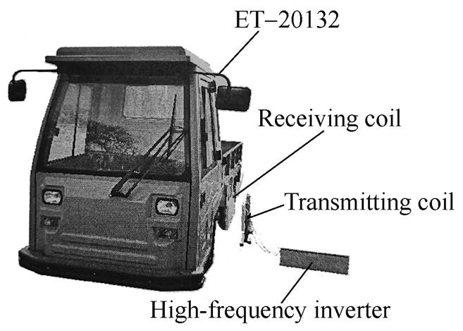
Fig.1 Wireless charging system implemented to the electric truck ЕТ-20132
Abstract The intensive development of electric vehicles contributes to advancing battery charging systems. One of the promising areas is wireless charging systems based on inductive power transfer. However, parameter optimization of the resonant circuit’s inductances and capacitances can affect the wireless charging system’s efficiency.
This paper aims to optimize the constraint efficiency of wireless charging systems with LC-series compensating topology at a given resonant frequency and a given distance between transmitting and receiving coils. The constraints reflect dimensional restrictions on coils, ensuring transferred power is within an input voltage limit and limiting excess voltages on components. A mathematical model is used that assumes load as active resistance, no loss besides the ohm one, and the idealized inverter, rectifier, and power supply. The optimization criteria include four components: (1) the efficiency function x1 to be maximized; (2) the constraint function x2 determining the amount of transferred power to be lower limited; (3) and (4) the constraint functions x3 and x4 determining the excess voltage on the primary and secondary capacitors that to be upper limited. The dependencies are established using a frequency domain to describe each component of the optimization criteria on the resonant circuit parameters of the wireless charging systems. Due to complexity, some resonant circuit parameters are treated as constants in the given circumstance and discarded. Next, the dependencies between the rest of the parameters are obtained using Chebyshev polynomial approximation through the least-squares method, reducing the parameters to the coil inductance L. Moreover, the dependencies x1(L)~x4(L) are compared with their boundary conditions. Thus, the resonant circuit parameters that fulfill optimization criteria are theoretically obtained.
The presented constrained efficiency optimization is validated using the specially-made wireless charging system for the electric truck ET-20132. Addressing various sources of loss, including those caused by the skin effect, transistors in the high-frequency inverter, diodes in the high-voltage bridge rectifier, and control schemes, is considered. Comparison of experiments and theoretical analysis shows good convergence at the resonant frequency 91.3 kHz, with acceptable deviations beyond the frequency range (approximately below 88 kHz and beyond 96 kHz). The wireless charging system normally operates within the frequency range of 91.3 kHz to 92.5 kHz, where the experimental load current closely aligns with the model, indicating that all the required power is transferred. Minimal average deviations between experiments and theoretical analysis are voltages on the primary and secondary side capacitors. The experimental results generally exceed model predictions. The efficiency can reach 91%.
Keywords: Electric vehicle, wireless charging system, resonant magnetic circuit, LC-series compensation, constrained efficiency optimization, transfer function, parameters approximation
Various kinds of electric vehicles with high- capacity batteries have been intensively developing in the last decade. Along with it, the infrastructure for charging their batteries is also elaborating. Currently, there are AC and DC charging systems with capacities from one to hundreds of kilowatts[1-2] in most of which the electric vehicle is plugged with a special electric cable. At the same time, there are wireless charging systems[3-4] including high-power ones that use the inductive power transfer technology based on transmitting the energy of high frequency alternating electromagnetic field in resonant mode from the transmitting coil to the receiving coil and so do not require a cable connection with electric vehicles to charge their batteries[5-6]. Elimination of direct connection increases the reliability of the charging system and contributes to the development of human-free self-driving vehicles, as battery charging can then be easily automated and performed without human involvement.
In the 20th century, there were only a few pieces of research related to wireless power transfer, but after the MIT publication[7] significant attention in this field was formed. One of the challenges is to optimize the parameters of wireless charging systems to provide the best efficiency and the maximum power transfer ratio.
To solve such a parameter optimization task, there are two mutually supplementing approaches. The first one is used at the development stage and performs the efficiency optimization of the wireless charging system for specified operating conditions. The second approach is used in exploitation and provides the best efficiency under changing operating conditions such as supply voltage deviations, the distance variations between the off-board transmitting coil and the on-board receiving coil, or the system load changes.
To optimize the wireless charging system in exploitation, the control system is used which depending on feedback from sensors makes adjust- ments, for example, voltage adjustment on the transmitting and receiving side[8] or changes of capacitance in the compensation topology circuits[9]. Such a control system gives the best result if the wireless charging system has the parameters already optimized at the design stage. Therefore, each of the optimization approaches deserves consideration. This research is focused on optimization at the develop- ment stage.
Since the central element of the wireless charging system is a spatially distributed electro- magnetic field, the most accurate parameters opti- mization at the development stage is performed using three-dimensional finite-element method[10]. For example, this method can be used for coil and magnetic-core shapes optimization to maximize the coupling coefficient[11].
However, using of three-dimensional finite- element method makes the designing and optimizing processes time-consuming and expensive in com- puting[12]. In fact, it provides certain optimal parameters of the wireless charging system equivalent scheme. That is why optimization based on the plain equivalent scheme does not consider how exactly the electromagnetic field is spatially distributed but works effectively enough. So, in this research, such an approach is chosen as preferred.
As an illustration of this approach, several publications can be mentioned that investigate the dependencies between the efficiency and the design of the transmitting and receiving coils of wireless charging systems as well as their horizontal and angular displacement, and propose the optimal design of the coils[13-20]. For instance, the optimization technique[19] ensures the minimization of the coils copper to maximize efficiency. In substance, they determine how the mutual inductance influence on the efficiency and power transfer ratio of the wireless charging system.
Optimization also can use dependencies of the efficiency and power transfer ratio on the load resistance that have their limits[21-23]. However, in practice, such optimization is hardly applicable, as the load resistance is determined by the type of battery being charged and there is no possibility to vary its value to reach the optimum.
Another way considers that when the resonant frequency is fixed, the efficiency, power transfer ratio, and other characteristics depend on the ratio of the inductances of the coils to the capacitance of the resonant circuit capacitors so the wireless charging system might be optimized through varying the values of compensating circuit parameters[24-25].
Given the above and considering that the implementation of wireless charging systems is related to technical constraints, this paper proposes the constrained efficiency optimization for such a system at the given resonant frequency and the given distance between the transmitting coil and the receiving coil. It is supposed that the optimization under discussion concerns the development stage than exploitation. The constraints reflect the required transferred power under the voltage limit of the power supply and the reliability of semiconductor switches and passive elements of the resonant circuit.
The research is carried out for the wireless charging system with LC-series compensating topology as it provides the best power transfer ratio[26] and the resonant frequency is minimally sensitive to the mutual inductance[27-30]. The last-mentioned property of the LC-series compensating topology ensures that the system has little sensitivity to distance changes between the coils since the mutual inductance is the only parameter that depends on the distance. That means even if the distance between the coils varies during operation, the wireless charging system will have the efficiency not far from the maximum.
For practical implementation and experimental validation of the proposed technique, the wireless charging system with a capacity of 3.6 kW is used which is applicable to electric truck ЕТ-20132 shown in Fig.1. This application imposes restrictions on the size of the receiving coil of 600 mm×300 mm, the nominal charging current for onboard traction batteries is 36 A at the voltage of 100 V, based on which the equivalent load resistance is approximately 2.8 W.
Fig.1 Wireless charging system implemented to the electric truck ЕТ-20132
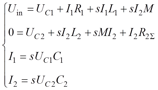
The wireless charging system under con- sideration consists of the dual-stage high-frequency inverter supplied from the industrial AC grid, the resonant circuit including transmitting and receiving coils with compensating capacitors, and the rectifier that charges the battery. The primary side of the resonant circuit is stationary, and the secondary side is on-board. The equivalent circuit of the wireless charging system with LC-series compensating topology is shown in Fig.2 and the mathematical model of this system in a time domain is as follows:
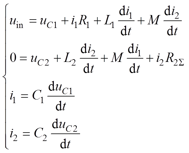 (1)
(1)
where uin is the input voltage; uC1 is the capacitor voltage at the primary side; uC2 is the capacitor voltage at the secondary side; i1 is the transmitting circuit current; i2 is the receiving circuit current that equal to the load current; R1, R2, C1, C2 are primary and secondary sides resistances and capacitances consequently; Rload is the equivalent resistance of the battery; R2Σ is sum (R2+Rload); L1, L2 are transmitting and receiving coils inductance consequently; M is mutual inductance between primary and secondary sides.
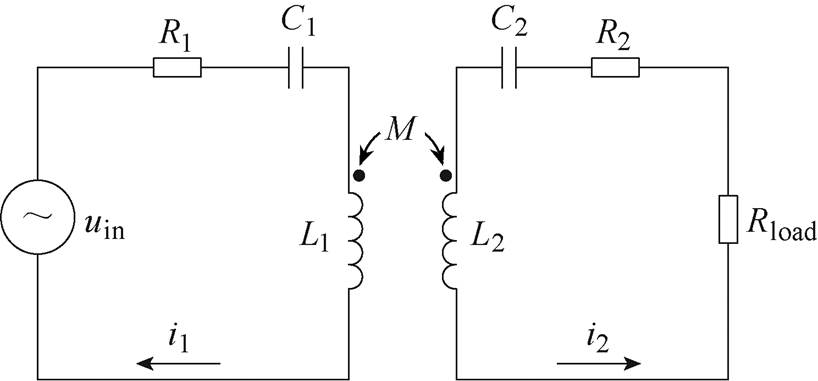
Fig.2 Equivalent circuit of the wireless charging system with LC-series compensating topology
The above mathematical model is given to the following assumptions: ① capacitor losses are not considered; ② the inverter and the rectifier are not regarded, and the power supply is ideal; ③ the load is active resistance, determined by the nominal current and charging voltage of the battery; ④ the current displacement effect is not considered.
As the main purpose of this research is the efficiency optimization of the wireless charging system, it is necessary to ensure the maximum efficiency of power transfer through the resonant circuit. Additionally, when developing the wireless charging system, there is a need to pay attention to the restrictions on the size of the transmitting and receiving coils and even more so to limitations on electrical parameters of the system associated with the reliability of semiconductor switches and passive elements of the resonant circuit like the permissible capacitor voltage in the resonant circuit. Another factor is obligatory to transfer through the resonant circuit no less than the required amount of power under the voltage limit of the power supply.
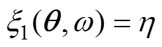
Based on the foregoing, the constraint opti- mization is suitable to the described task and the optimization criteria can be mathematically repre- sented as follows
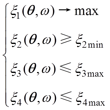 (2)
(2)
where x1(q, w) is the efficiency function to be maximized; x2(q, w) is the constraint function determining the amount of transferred power to be lower limited; x3(q, w), x4(q, w) are the constraint functions determining the excess voltage on the primary side capacitor and the secondary side capacitor to be upper limited; w is the angular frequency of the resonant circuit currents and voltages; q =[R1 C1 L1 M R2 C2 L2 Rload]T is the resonant circuit parameters vector; x2min(q, w),x3max(q, w), x4max(q, w) are the boundary conditions of the corresponding functions that define the area of efficiency optimization.
As the optimization under discussion concerns the development stage, the main idea is to realize the parameter optimization i.e. to find the optimal components of q ensuring the optimization criteria (2) fulfillment. To get the optimization criteria in the parametric form transfer functions are used. It is the appropriate tool because the mathematical model (1) of the wireless charging system is linear, and a transfer function being input-output relation can be regarded as a transient parameter. For example, if a voltage is an input and a current is an output, such a transfer function represents a transient conductance. Additionally, transfer functions allow analyzing the system in the frequency domain hence taking the resonant frequency into account. To use this tool the Laplace transform is applied to the mathematical model (1):
 (3)
(3)
where s is the Laplace variable.
To define the abovementioned functions of the optimization criteria, each component of Equ. (2) should be considered separately.
1) The efficiency function
 (4)
(4)
where h is efficiency that might be expressed as the following
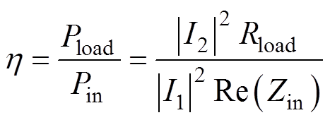 (5)
(5)
where Pload is the power delivered to the load; Pin is the power consumed from the input; Zin is the input impedance.
From the Equ. (3), considering the input voltage Uin as the input and the load current I2 as the output, the following transfer function can be derivable:
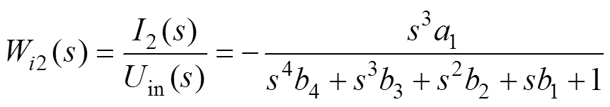 (6)
(6)
where
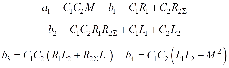
that in the frequency domain is
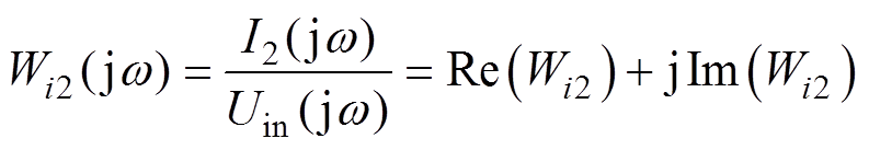 (7)
(7)
where
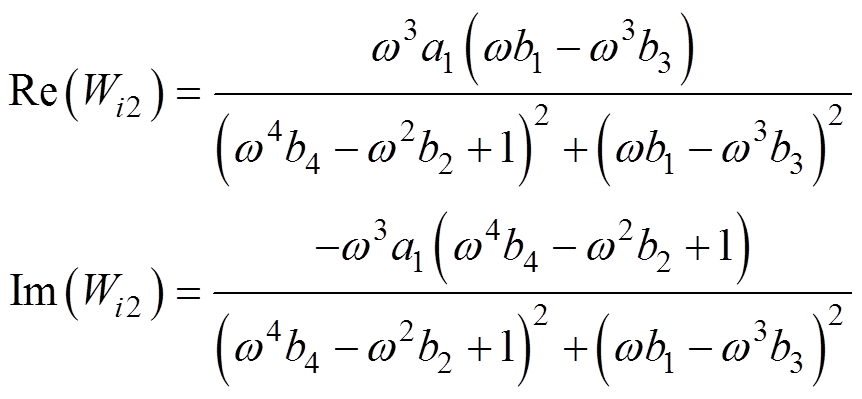
Taking Uin(jw)=|Uin|ej0, the amplitude-frequency response Ai2 of the transfer function Wi2 provides calculating the numerator of Equ. (5):
 (8)
(8)
where
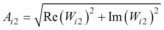 (9)
(9)
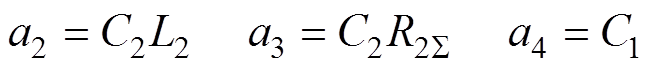
In a similar manner, taking the input voltage Uin as the input and the transmitting circuit current I1 as the output, the transfer function Wi1 provides calculating the denominator of Equ. (5). The course of computation is the following. From Equ. (3), the transfer function Wi1 in the s-domain is
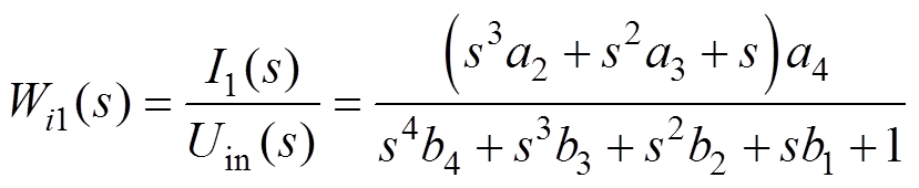 (10)
(10)
where
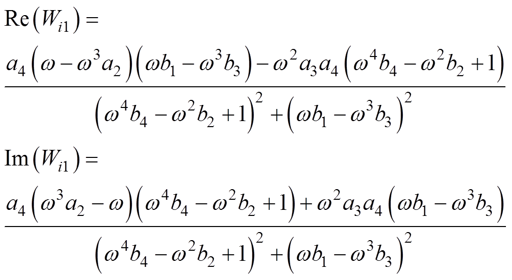
and in the frequency domain is
 (11)
(11)
where
Bearing in mind that Uin(jw)=|Uin|ej0, the power consumed from the input is
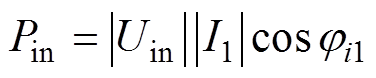 (12)
(12)
whereji1 is the phase-frequency response of the transfer function Wi1. Hence expressing I1(jw) through Uin(jw) and Wi1, and recovering the rectangular coordinates from the polar form, the input power can be rewritten:
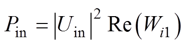 (13)
(13)
Thus, efficiency function Equ. (3) has been expressed only by components of q
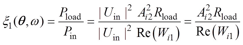 (14)
(14)
and so is capable of parameter optimizing.
2) The constraint function determining the amount of transferred power
The assumptions made in the mathematical model Equ. (1) include that the wireless charging system works on a constant active load and the rectifier is ideal consequently, the transferred power is equal to the power delivered to the load, and its amount depends on the load current. Thus, the amplitude-frequency response Ai2 Equ. (9) can be used as the constraint function x2.
The corresponding boundary condition should incorporate the required amount of power under the voltage limit that might be expressed as the following ratio:
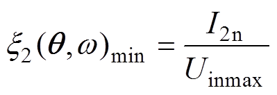 (15)
(15)
where I2n is the nominal load current; Uinmax is the maximum input voltage.
Thus, the constraint function x2 as the component of Equ. (2) is
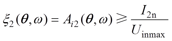 (16)
(16)
that is expressed only by components of q.
3) The constraint functions determining the excess voltage on the capacitors

In the wireless charging system, the reference for the excess voltage on the primary side capacitor and the secondary side capacitor is the input voltage, hence
 (17)
(17)
To express the above constraint functions through the components of q the following transfer functions are used:
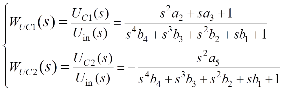 (18)
(18)
where a5=C1M, that after transforming into the frequency domain produce the following amplitude- frequency responses:
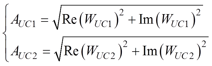 (19)
(19)
where
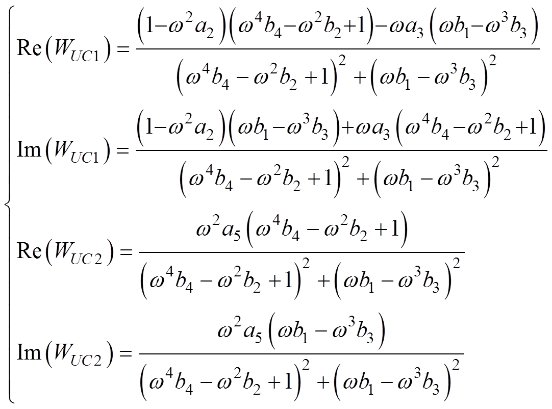 (20)
(20)
are suitable for use as the constraint functions x3 and x4.
The corresponding boundary conditions can be defined as
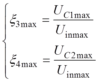 (21)
(21)
where UC1max and UC2max are the maximum per- missible voltages of the primary side capacitor and the secondary side capacitor, ensuring their reliability.
Thus, the constraint functions x3 and x4 as the components of Equ. (2) are the following
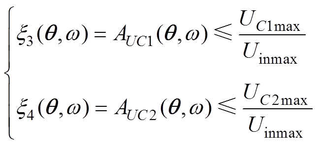 (22)
(22)
Defining the functions x1~x4 allows us to analyze them in the frequency domain. Fig.3 shows these functions for the wireless charging system applicable to the electric truck ЕТ-20132 and depicts that the maximum of the efficiency function x1 does not coincide in frequency with either the first or the second maximum of the constraint function x2 determining the amount of transferred power but is located between them. In the frequency range between the maxima of x2, the value of x1 changes up to 0.3% from its maximum. At the same time, the maximum of x1 is close in frequency to the minimum ofx2. Thus, it is reasonable to choose the first maximum ofx2 as the resonant frequency fr of the wireless charging system. Still, the operating frequency fo is worthwhile to set slightly higher because it is the opportunity to achieve the balance where the efficiency is closer to the maximum plus the amount of transferred power is in the range of 70%~90% of the maximum possible value that is enough for operational stability.
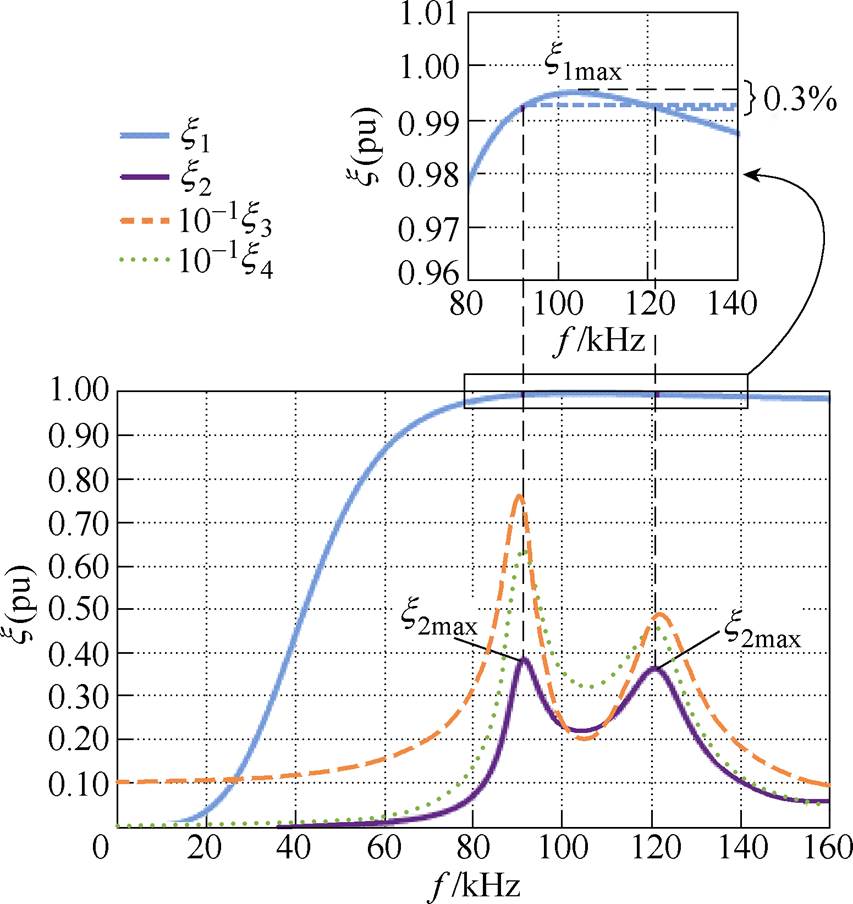
Fig.3 Components of the optimization criteriax1~x4in the frequency domain
The proposed constraint optimization of the wireless charging system concerns only the develop- ment stage and is considered as parameter opti- mization. The algorithm of the optimization technique is shown in Fig.4. To solve the task, the optimization criteria Equ. (2) have been determined in terms of the resonant circuit parameters but the dimension of vector q is too high to reach the direct analytical solution. To circumvent this difficulty all parameters issued as constants are discarded and the rest of the parameters are reduced to one.
The assumptions made in the mathematical model (1) include that the wireless charging system works on a constant active load, hence Rload is constant, which value for the batteries of the electric truck ET-20132 is equal to 2.8 W. Under the recom- mendation of the standard J2954[31], the resonant frequency fr is constant as well and is set to 90 kHz.
Reducing the rest of the parameters to one parameter has the following basis:
(1) The resonant circuit with LC-series compen- sating topology is symmetric, that means L1=L2=L, R1=R2=R, and C1=C2=C.
(2) The transmitting and receiving coils are flat and square-shaped, the size of the receiving coil is fixed by technical restrictions, and the distance between the coils is constant. Hence L, R, and M are directly specified by the coils’ size, distance, and winding parameters.
(3) The wireless charging system operates with the given resonant frequency. If L, R, and M are given, C is no longer the independent parameter as there is only a specific capacity providing that the resonant frequency has the given value.
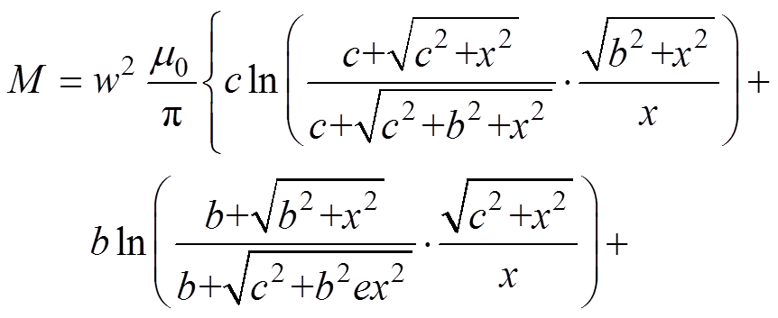
In the above conditions according to P. L. Kalantarov and L. A. Zeitlin manual[32] the coils’ inductances are as follows:
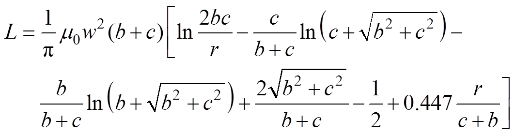 (23)
(23)
where m0 is the magnetic permeability of the air; w is the turn number; b and c are the lengths of the edges; r is the winding width. And the mutual inductance is calculated as
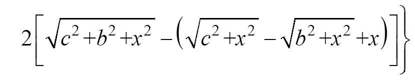 (24)
(24)
where x is the distance between the coils.
The primary and secondary sides resistances are the coil resistance hence they are calculated as
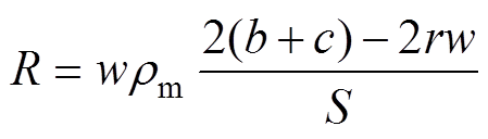 (25)
(25)
where S is the cross-section of the coil wire; rm is the resistivity of the coil wire.
Analysis of the equations describing L, M, and R shows that the only variable for the given geometry and materials for the coils’ windings is the turn number w. The same is true for C as the resonant frequency is also given. However, it is difficult to define the analytical expression for C because the equation describing the resonant frequency fr corresponding to the mathematical model Equ. (1) has a high dimension. That is why the capacitance C is obtained with numerical methods by a specially written computer program based on Equ. (9) where the resonant frequency has been appointed to the first maximum of the amplitude-frequency response Ai2. Tab.1 shows the computational results with the turn number from 1 to 12.
Reducing the parameters of the wireless charging system to the turn number w provides the constraint optimization as it is, however, this parameter is not used in the mathematical model Equ. (1) and the optimization criteria Equ. (2). Consequently, it is appropriate to set using Equ. (23) the direct link between the turn number w and the coil inductance L and henceforth use the last one as the only variable in the task under consideration. Dependencies of the other parameters on the coil inductance are defined by the functions M=f(L), R=f(L), and 1/C=f(L) obtained from Tab.1 data using the least-squares method for Chebyshev polynomial approximation. Fig.5 shows the resulting 3-order polynomials and Tab.2 presents RMS errors for Chebyshev polynomials of order from 1 to 3.

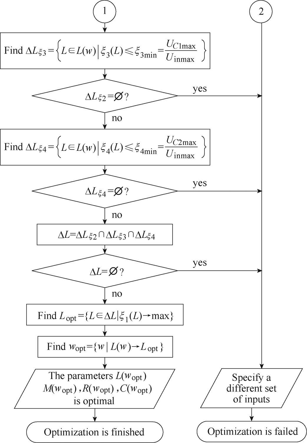
Fig.4 The proposed constrained efficiency optimization algorithm
Tab.1 Resonant circuit parameters
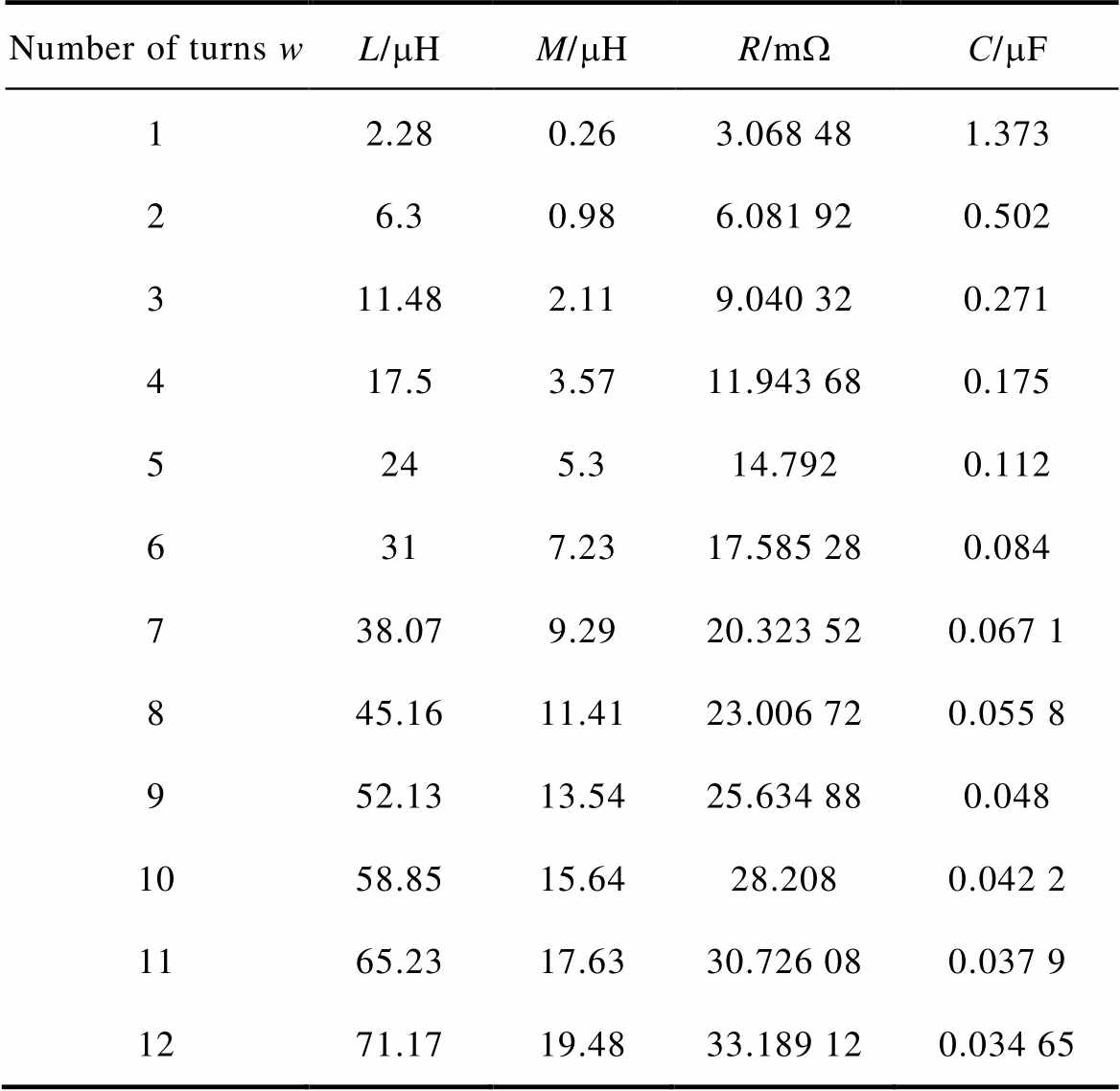
Number of turns wL/mHM/mHR/mWС/mF 12.280.263.068 481.373 26.30.986.081 920.502 311.482.119.040 320.271 417.53.5711.943 680.175 5245.314.7920.112 6317.2317.585 280.084 738.079.2920.323 520.067 1 845.1611.4123.006 720.055 8 952.1313.5425.634 880.048 1058.8515.6428.2080.042 2 1165.2317.6330.726 080.037 9 1271.1719.4833.189 120.034 65
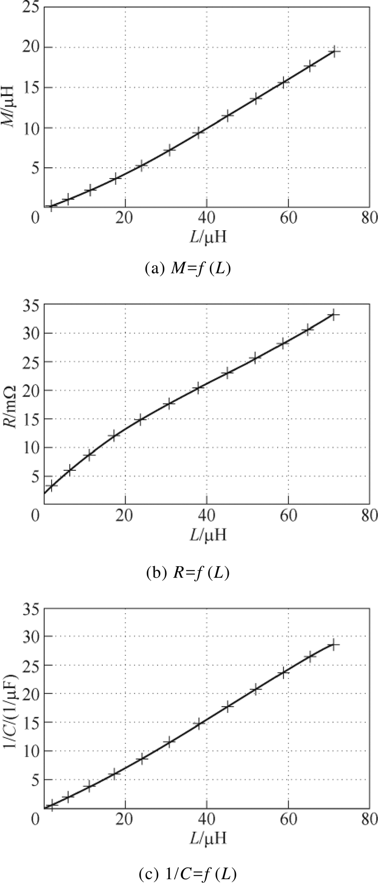
Fig.5 The results of parameters approximation with 3-order Chebyshev polynomials
Tab.2 RMS errors of Chebyshev polynomial approximation (%)

FunctionOrder of polynomial 123 R=f(L)14.7145.61.6 M=f(L)3.22.20.8 1/C=f(L)209.38.31.7
Tab.2 gives clear evidence that using 3-order polynomials provides the maximal approximation accuracy as RMS error for all parameters does not exceed 2%, thus in the functions x1~x4 of the optimization criteria (2) it is allowable to use the following:
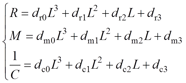 (26)
(26)
where dr0~dr3, dm0~dm3, dc0~dc3 are polynomial coefficients given in Tab.3.
Tab.3 Polynomial coefficients
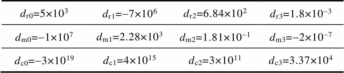
dr0=5×10³dr1=-7×10⁶dr2=6.84×10²dr3=1.8×10⁻³ dm0=-1×10⁷dm1=2.28×10³dm2=1.81×10⁻¹dm3=-2×10⁻⁷ dc0=-3×10¹⁹dc1=4×10¹⁵dc2=3×10¹¹dc3=3.37×10⁴
Applying Equ. (26) into Equ. (2), functions x1~x4 possess the coil inductance L as the only variable. Dependencies x1(L)~x4(L) are presented in Fig.6 where the areas outside the boundary conditions are highlighted in gray.
The values of the boundary conditions x2min, x3max, and x4max are obtained based on the technical characteristics of the wireless charging system for the electric truck ET-20132.
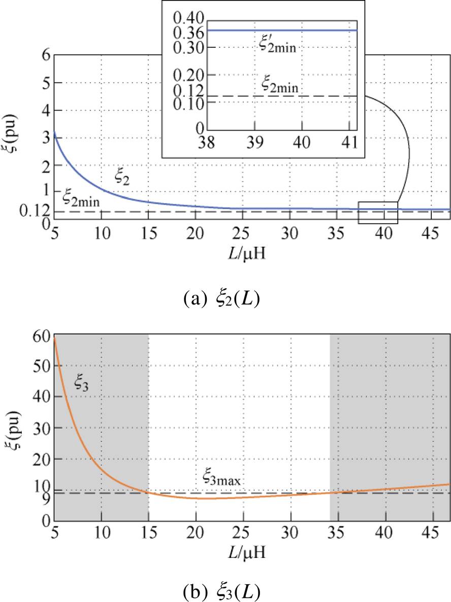

Fig.6 Components of the optimization criteriax1(L)~x4(L) in dependence on the coil inductance
Thus, using the maximum supply voltage of 300 V as the maximum input voltage and the nominal load current of 36 A, the minimal amount of trans- ferred power is
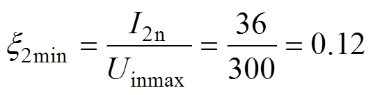
and Fig.6a shows that in this case, the constraint function x2 does not go beyond the boundary. That menace the amount of transferred power will be higher than required, hence the input voltage used has to be lowered by the high-frequency inverter and it does not cause any disturbance in the normal operation of the wireless charging system. The minimum value of x2 is  =0.36, so for I2n =36 A, the input voltage becomes Uinmax=I2n/
 =100 V.
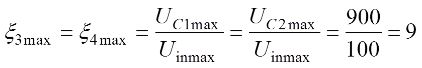
Considering the maximum permissible voltages of the resonant circuit capacitors are equal and have the value of 900 V, the maximum excesses of voltages are
As can be seen from Fig.6b and Fig.6c, the constraint functions x3 and x4 do not go beyond the boundaries if the coil inductance L is between 15 mH and 34 mH. Hence, analysis of the efficiency function x1 in this range solves the parameter optimization task.
According to Fig.6d, at the range of L providing x2(L)≥x2min, x3(L)≤x3max, and x4(L)≤x4max, which indicates the optimization criteria (2) fulfillment, the maximum of the efficiency function x1 corresponds to L=22.5 mH. It should be noted that this value of the coil inductance is not feasible, as the turn number w must be an integer. The closest turn number w=5 gives the quasi-optimal solution. Thus, the proposed constraint optimization results in the resonant circuit parameters given in Tab.1 for turn number w is 5.
To prove the obtained results experimentally, the wireless charging system for the electric truck ET-20132 has been made. Part of the system equipment has been manufactured including two flat and square-shaped coils with edges of 600 mm× 300 mm length and the turn number of 5, the high-frequency inverter from SMPS MOSFET transistors IRFP90N20DPbF, and the high-voltage bridge rectifier from STPS160H100TV power Schottky diodes in the battery charging circuit. In addition to the above, the system contains metal-film capacitor B32682A1472K000 as the primary and secondary sides capacitors, and also a DC power supply DELTA ELEKTRONIKA SM 330-AR-22, a digital RLC meter MASTECH MS-5308, an OWON SDS7102V digital oscilloscope, a MASTECH MS2109A current clamp, a Sonel CMM-10 multimeter. The complete equipment set included in this wireless charging system is shown in Fig.7a. To conduct experiments the receiving coil has been attached to the frame of ET-20132, as shown in Fig.7b, and connected to the batteries through the rectifier and LC filter. The transmitting coil connected to the inverter has been placed in parallel-alignment with the receiving coil at the distance of 100 mm.
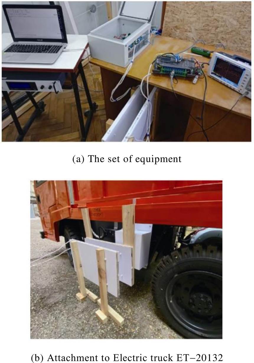
Fig.7 The experimental wireless charging system
As the experimental wireless charging system is not ideal, and foremost the resonant circuit with LC-series compensating topology is not precisely symmetric, the real resonant circuit parameters do not similar to the corresponding ones in Tab.1 for the row for w=5. That is why the real parameters of the wireless charging system for the electric truck ET-20132 have been measured before carrying out any experiments. The results are shown in Tab.4 and demonstrate the average deviation of measured parameters from data in Tab.1 of 2% and the resonant circuit asymmetry of 0.86%.
Tab.4 Parameters of the experimental wireless charging system
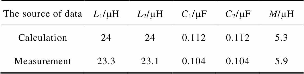
The source of dataL1/mHL2/mHС1/mFС2/mFM/mH Calculation24240.1120.1125.3 Measurement23.323.10.1040.1045.9
It should also be noted the mathematical model (1) describes only the ohm losses DPohm and does not consider most part of the losses there are in the experimental wireless charging system like switching and conductive losses in the semiconductor switches of the high-frequency inverter and the high-voltage bridge rectifier, the dielectric losses in resonant circuit capacitors, etc. To make the experimental efficiency assessment more consistent, Fig.8 shows the block diagram of the experimental wireless charging system indicating losses being considered in the comparison of the calculation and the experiment.
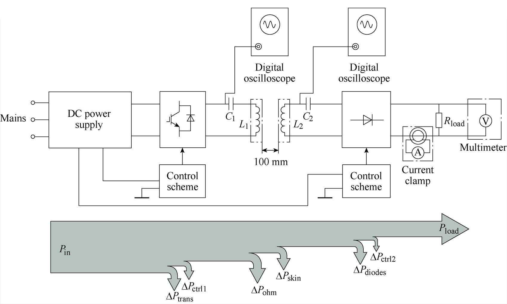
Fig.8 Block diagram of the experimental wireless charging system indicating losses
The first losses that should be considered in Fig.8 are caused by the skin effect DPskin. The skin effect does not affect the coil’s inductance but affects additional ohm losses in the coils that are associated with current displacement in the coil’s wire at high-frequency operation. The value of DPskin might be supplemented in the mathematical model Equ. (1) by the increase in R1 and R2. This increase has been measured with the digital RLC meter and at the resonant frequency, it is equal to 0.16 W. Thus, Fig.9 shows x1~x4 in the frequency domain calculated for the pure set of parameters from Tab.4 (ideal model) and for the increase in resistance (model considering skin effect).
The experiments with the wireless charging system implied the measurement of currents and voltages. At the inverter input the sensors imple- mented at the DC power supply are used and the current clamp along with the multimeter is used at the battery pack. At the resonant circuit capacitors, the digital oscilloscope is used where the built-in soft- ware makes pre-processing. All the data is transmitted to the PC where it is post-processed including the efficiency determination. Together with the calcu- lation, Fig.9 shows the experimental results of the wireless charging system for the electric truck ЕТ-20132. Additionally, for the efficiency h (the efficiency functions x1) the losses-correction has been made. It includes supplementing of the following losses: DPtrans in the transistors at the high-frequency inverter; DPdiodes in the diodes at the high-voltage bridge rectifier; DPctrl1 and DPctrl2 in control schemes at the transmitting and receiving side that are equal to 4 W and 2 W consequently. The value of DPtrans is assessed as squared current I1 multiplied by the on-state resistance of two simultaneously opened transistors which is 0.023 W for each. The value of DPdiodes is twice for current I2 multiplied by 0.68 V of voltage drop for two simultaneously opened diodes.
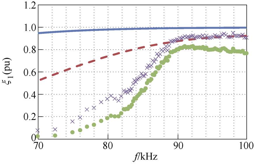
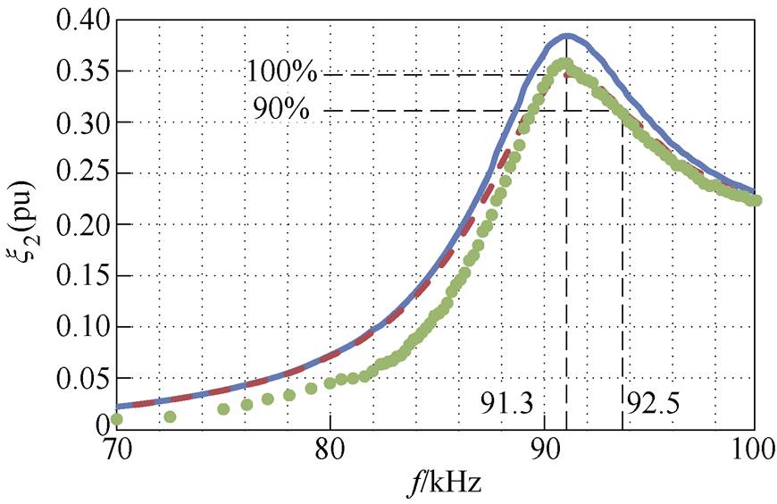
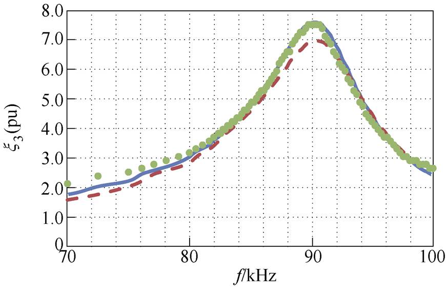
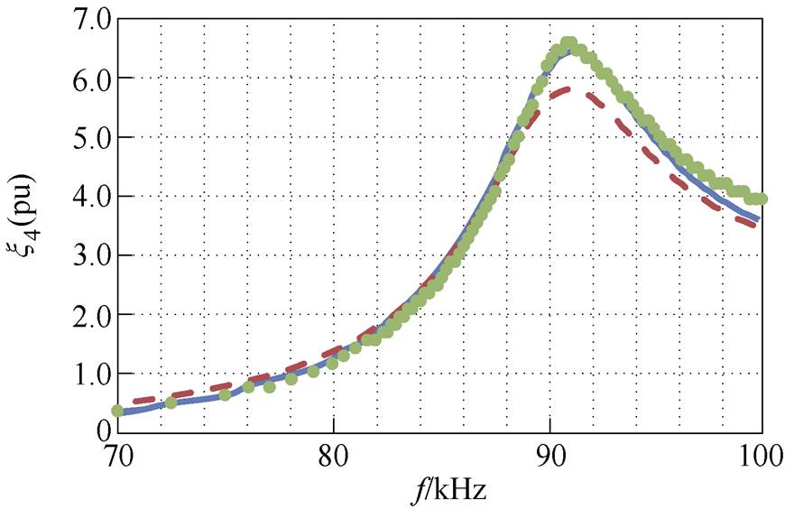
Fig.9 Components of the optimization criteria x1~x4 in the frequency domain: ideal model (solid lines); model considering skin effect (dashed lines); experiment (dot-labeled lines); losses-corrected experiment (cross-labeled lines)
As can be seen in Fig.9, the proposed constraint optimization rather well provides the resonant frequency. Thus, at the start (input block at Fig.4), the resonant frequency is set to 90 kHz, and at the finish, the experimental wireless charging system has fr=91.3 kHz. This slight change in the resonant frequency is caused by the parameter deviations and the resonant circuit asymmetry that demonstrates in Tab.4.
The comparison of the calculation and the experiment is reasonable to make using not the ideal model but the model considering the skin effect. Such comparison shows good convergence at the resonant frequency. The deviations of the experiment from the calculation exteriorly the resonant frequency (the approximate frequency range less than 88 kHz and more than 96 kHz) that reveal primarily at the efficiency h (the efficiency functions x1) are caused by the assumptions used in the mathematical model Equ. (1) such as the non-linearity of the experimental setup, firstly at the rectifier diodes and the anti-eddy batteries.
The smallest average difference is seen for UC1 and UC2 (the constraint functions x3 and x4), but these experimental values are mostly higher than even for the ideal model which might be caused by the additional capacitance of the real wireless charging system associated with the measuring instrument.
The experimental load current I2 (the constraint function x2) is convergent with the model considering the skin effect either at the resonant frequency fr=91.3 kHz and at the frequency range up to 92.5 kHz where x2 does not drop below 90% of its maximum and consequently where the operating frequency fo might be. That means all the required amount of power will be transferred at any normal operating conditions.
The efficiency h (the efficiency functions x1), obtained directly through the experiment is the efficiency of whole the wireless charging system including auxiliaries. It has the maximum value of 82.9% at the frequency 92.3 kHz. But in the majority of cases of current high-power systems[4], the declared efficiency refers only to inductive power transfer, hence the comparable efficiency is obtained after losses-correction. The losses-corrected efficiency has the maximum value of 94.8% at 98.1 kHz which is too far from the resonant frequency. Considering the frequency range from 91.3 kHz up to 92.5 kHz, the average losses-corrected efficiency is 91%. In ideal conditions where the skin effect in the coil’s wire is completely suppressed, the maximum efficiency h at the permissible operating frequency fo has the value of 99.2%.
All of the above confirms that the wireless charging system normally operates at the frequency range from 91.3 kHz up to 92.5 kHz, hence the assumptions made and caused by them the difference between the calculation and the experiment do not cast doubt on the validity of the mathematical model Equ. (1) for practical use. Consequently, the proposed constraint optimization functions properly in the described conditions.
The presented constrained efficiency optimi- zation is appropriate for the wireless charging system with LC-series compensating topology where the transmitting and receiving coils are flat and square-shaped, the size of the receiving coil is fixed by technical restrictions, and the distance between the coils is constant. Being used at the development stage for the given resonant frequency it provides the maximum efficiency within the amount of transferred power above the required value under the input voltage limit and within the excess voltage on the resonant circuit capacitors less than permissible values. The advantage of the proposed optimization technique is maximizing the system efficiency in the given circumstances without the need to use complex three-dimensional models. The disadvantage is that, due to the assumptions made in the mathematical model, if the parameters of the LC-series com- pensating topology circuit of the real wireless charging system deviate from the theoretically obtained, a shift in the resonant frequency may occur.
For the wireless charging system of the electric truck ET-20132 equipped with flat and square-shaped coils with edges of 600 mm×300 mm length and operating at the frequency range from 91.3 kHz up to 92.5 kHz, the theoretically possible efficiency is 99.2%. Considering the losses in semiconductor switches, the losses in rectifier diodes, and the losses to auxiliaries, the experimentally proven efficiency of the wireless charging system is 91%, which is good enough for this type of device in comparison with current high-power systems.
Reference
[1] Lee H, Clark A. Charging the future: challenges and opportunities for electric vehicle adoption[J]. SSRN Electronic Journal, 2018, RWP18-026: 1-77.
[2] Sanguesa J A, Torres-Sanz V, Garrido P, et al. A review on electric vehicles: technologies and challenges[J]. Smart Cities, 2021, 4(1): 372-404.
[3] 李阳, 石少博, 刘雪莉, 等. 磁场耦合式无线电能传输耦合机构综述[J]. 电工技术学报, 2021, 36(增刊2): 389-403.
Li Yang, Shi Shaobo, Liu Xueli, et al. Overview of magnetic coupling mechanism for wireless power transfer[J]. Transactions of China Electrotechnical Society, 2021, 36(S2): 389-403.
[4] Foote A, Onar O C. A review of high-power wireless power transfer[C]//2017 IEEE Transportation Elec- trification Conference and Expo (ITEC), Chicago, IL, USA, 2017: 234-240.
[5] Omer C Onar, Larry Seiber, Cliff White, et al. Wireless charging of electric vehicles[M]. Oak Ridge: Oak Ridge National Laboratory, 2016.
[6] Zhang Bo, Carlson R B, Smart J G, et al. Challenges of future high power wireless power transfer for light-duty electric vehicles: technology and risk management[J]. eTransportation, 2019, 2: 100012.
[7] Kurs A, Karalis A, Moffatt R, et al. Wireless power transfer via strongly coupled magnetic resonances[J]. Science, 2007, 317(5834): 83-86.
[8] Diekhans T, De Doncker R W. A dual-side controlled inductive power transfer system optimized for large coupling factor variations and partial load[J]. IEEE Transactions on Power Electronics, 2015, 30(11): 6320-6328.
[9] Zhang Jianzhong, Zhao Jin, Zhang Yaqian, et al. A wireless power transfer system with dual switch- controlled capacitors for efficiency optimization[J]. IEEE Transactions on Power Electronics, 2020, 35(6): 6091-6101.
[10] Bandyopadhyay S, Venugopal P, Dong Jianning, et al. Comparison of magnetic couplers for IPT-based EV charging using multi-objective optimization[J]. IEEE Transactions on Vehicular Technology, 2019, 68(6): 5416-5429.
[11] Otomo Y, Igarashi H. A 3-D topology optimization of magnetic cores for wireless power transfer device[J]. IEEE Transactions on Magnetics, 2019, 55(6): 1-5.
[12] Hariri A, Elsayed A, Mohammed O A. An integrated characterization model and multiobjective optimi- zation for the design of an EV charger’s circular wireless power transfer pads[J]. IEEE Transactions on Magnetics, 2017, 53(6): 1-4.
[13] Gao Pengfei, Tian Zijian, Pan Tao, et al. Trans- mission efficiency analysis and optimization of magnetically coupled resonant wireless power transfer system with misalignments[J]. AIP Advances, 2018, 8(8): 1-10.
[14] Huang Wei, Ku H. Analysis and optimization of wireless power transfer efficiency considering the tilt angle of a coil[J]. Journal of Electromagnetic Engin- eering and Science, 2018, 18(1): 13-19.
[15] Kim Y H, Kang S Y, Lee M L, et al. Optimization of wireless power transmission through resonant coupling[C]//2009 Compatibility and Power Elec- tronics, Badajoz, 2009: 426-431.
[16] Orekan T, Zhang Peng, Shih C. Analysis, design, and maximum power-efficiency tracking for undersea wireless power transfer[J]. IEEE Journal of Emerging and Selected Topics in Power Electronics, 2018, 6(2): 843-854.
[17] Ishida H, Furukawa H, Kyoden T. Development of design methodology for 60Hz wireless power trans- mission system[J]. IEEJ Journal of Industry Appli- cations, 2016, 5(6): 429-438.
[18] Yan Yixin, Shi Wan, Zhang Xiaobing. Design of UAV wireless power transmission system based on coupling coil structure optimization[J]. EURASIP Journal on Wireless Communications and Networking, 2020, 2020(1): 1-13.
[19] Yildiriz E, Kemer S B, Bayraktar M. IPT design with optimal use of spiral rectangular coils for wireless charging of e-tricycle scooters[J]. Engineering Science and Technology, an International Journal, 2022, 33: 101082.
[20] 张献, 杨庆新, 崔玉龙, 等. 大功率无线电能传输系统能量发射线圈设计、优化与验证[J]. 电工技术学报, 2013, 28(10): 12-18.
Zhang Xian, Yang Qingxin, Cui Yulong, et al. Design optimization and verification on the power trans- mitting coil in the high-power wireless power trans- mission system[J]. Transactions of China Electro- technical Society, 2013, 28(10): 12-18.
[21] Borong Hu, Li Ran. High efficiency with multi load wireless power transmission[C]//International Russian- Sino Student Competition, Perm, Russia, 2015: 148- 159.
[22] Truong B D, Andersen E, Casados C, et al. Mag- netoelectric wireless power transfer for biomedical implants: effects of non-uniform magnetic field, alignment and orientation[J]. Sensors and Actuators A: Physical, 2020, 316: 112269.
[23] Zheng Zhongjiu, Wang Ning, Ahmed S. Maximum efficiency tracking control of underwater wireless power transfer system using artificial neural networks[J]. Proceedings of the Institution of Mechanical Engineers, Part I: Journal of Systems and Control Engineering, 2021, 235(10): 1819-1829.
[24] Zavylov V M, Semykina I, Abeidulin S A, et al. Criteria for choosing of resonant circuit parameters of wireless power transfer charging system[J]. Iranian Journal of Electrical and Electronic Engineering, 2022, 18: 2236.
[25] Chaurasia D, Ahirwar S. An optimal parameter estimation technique for wireless electricity trans- mission[J]. Advances in Electronic and Electric Engineering, 2013, 3(1): 1-9.
[26] 程鹏天, 王健强, 杜秀. 电动汽车感应耦合充电系统一种新型拓扑的研究[J]. 电工技术学报, 2013, 28(增刊2): 86-91.
Cheng Pengtian, Wang Jianqiang, Du Xiu. Investi- gation of a novel topology for inductively coupled charging system in electric vehicles[J]. Transactions of China Electrotechnical Society, 2013, 28(S2): 86-91.
[27] Zhang Wei, Mi C C. Compensation topologies of high-power wireless power transfer systems[J]. IEEE Transactions on Vehicular Technology, 2016, 65(6): 4768-4778.
[28] Jayalath S, Khan A. Design, challenges, and trends of inductive power transfer couplers for electric vehicles: a review[J]. IEEE Journal of Emerging and Selected Topics in Power Electronics, 2021, 9(5): 6196-6218.
[29] Shevchenko V, Husev O, Strzelecki R, et al. Com- pensation topologies in IPT systems: standards, requirements, classification, analysis, comparison and application[J]. IEEE Access, 2019, 7: 120559-120580.
[30] Panchal C, Stegen S, Lu Junwei. Review of static and dynamic wireless electric vehicle charging system[J]. Engineering Science and Technology, an International Journal, 2018, 21(5): 922-937.
[31] SAE J2954 Wireless power transfer for light-duty plug-in/electric vehicles and alignment methodo- logy[S].
[32] Kalantarov P L, Zeitlin L A. Calculation of indu- ctances[M] Leningrad: Energoatomizdat. Leningrad branch, 1986.
摘要 开发基于感应功率传输的无线充电系统是一个很有前途的研究领域。本研究的目的在于,在给定谐振频率和给定发射线圈和接收线圈之间距离的情况下,优化具有LC串联补偿拓扑结构的无线充电系统的约束效率。这些约束反映了线圈的尺寸限制、输入电压限制下所需的传输功率,以及部件上的过电压。为了达到目标,制定了优化标准。已经为频域中优化标准的每个组件建立了对无线充电系统谐振电路参数的依赖性。由于这些依赖关系看起来非常复杂,在给定的情况下利用参数之间的联系,并采用最小二乘法的切比雪夫多项式近似,它们在优化任务中被简化为一个变量。因此,理论上已经获得了指示优化标准满足的谐振电路参数。利用为电动卡车ET-20132专门制造的无线充电系统对所提出的约束效率优化方法进行了实验验证。实验和理论的比较表明,它们在谐振频率上具有良好的收敛性,由数学模型中的假设引起的谐振频率偏差是可接受的。经实验证明,无线充电系统的效率为91%。
关键词:电动汽车 无线充电系统 谐振磁路 LC串联补偿 约束效率优化 传递函数 参数近似
中图分类号: TM724
DOI: 10.19595/j.cnki.1000-6753.tces.222371
The research was supported by the state assignment of Ministry of Science and Higher Education of the Russian Federation (075-03- 2021-138/3).
Received Dec.28, 2022;
Revised Feb.28, 2023.
Notes Brief
Valery Zavyalov male, born in 1974, USSR. He received his PhD. in 2003 and DSc. in 2009 degrees in Electrotechnical Complexes and Systems from Kuzbass State Technical University. His area of scientific interests includes control of electromechanical trans- formation of energy, identification of parameters and condition of electric drives, dynamic loadings decrease in mechanical transfers by means of the adjustable electric drive; spatial electric drives in robotics and electric vehicles.E-mail: VMZavyalov@sevsu.ru
Irina Semykina female, born in 1984, USSR. She graduated from Kuzbass State Technical University in 2005 and received DSc. in Electrotechnical Complexes and Systems from Tomsk Polytechnic University in 2014. Her scientific interests include energy saving, electrical equipment, automation, control of complex dynamic systems, and electrical engineering.E-mail: arinasemykina@gmail.com (Corresponding author)
(编辑 郭丽军)