
图1 传统管件胀形与双层集磁器管件胀形对比
Fig.1 Comparison of traditional tube bulging and double-layer magnetic field shaper tube bulging
摘要 针对传统管件电磁胀形存在管件壁厚减薄严重和变形不均匀等问题,提出基于双层凹型集磁器结构的单线圈管件电磁成形方法,通过径向电磁力场分布的调控和轴向电磁力的协同加载,为同时抑制管件壁厚减薄和改善变形均匀性提供了新的技术途径。为验证该方法的有效性,基于电磁-结构场耦合数值模型,对比探究有无双层凹型集磁器下轴径电磁力分布特性、管件壁厚减薄量以及轴向变形均匀性等关键物理量的变化规律,研究集磁器的内凹高度对管件成形行为的影响。仿真结果表明,与传统管件电磁胀形方法相比,新方法下管件壁厚减薄量可从22.07%降低至8.30%,且轴向均匀性扩大至2.31倍。
关键词:电磁成形 电磁力 集磁器 变形行为
应用轻质合金材料是航空航天、汽车等领域提高装备运载能力、实现节能减排的重要途径[1]。然而,以铝合金为代表的轻质合金材料在传统准静态成形工艺下成形性能普遍较差,存在易破裂、回弹大和表面质量欠佳等问题[2]。基于脉冲电磁力驱动金属工件发生塑性变形的电磁成形技术具有非接触、高速率、单模具等特征,可以显著提高材料的成形极限和改善成形性能,已在铝合金板管件成形中得到广泛应用[3-10]。
管件电磁成形根据电磁力加载方向与成形效果的差异可分为管件电磁胀形和管件电磁压缩。在管件电磁胀形中,通常采用单驱动线圈为管件加工提供电磁胀力,由于线圈在管件处产生的轴向磁通远大于径向磁通,因此传统管件胀形中管件主要受到径向电磁力的作用,且呈现“两端小,中间大”的分布特征[11-14]。这也使得管件变形行为往往呈现非均匀变形特征,且随着管件变形量的增大,壁厚减薄严重,导致成形量受限。为了解决管件变形不均匀问题,研究人员主要通过采用多线圈系统或改变线圈结构的方式。欧阳少威等提出三线圈双电源成形系统,通过调节线圈放电电压,从而改变洛伦兹力分布,进而改善管件轴向变形不均匀问题[15]。邱立等提出通过凹型线圈削弱管件中部成形区域径向电磁力的方法改善管件变形不均匀现象[16]。为了解决管件减薄问题,张骁等提出在双线圈系统加载不同脉宽电流方法,结果表明当管件变形深度相等时,通入长脉宽电流能有效改善管件减薄现象[17]。邱立等提出双线圈管件电磁胀形方案,通过双线圈轴向压缩和径向胀形同步加载,从而改善管件壁厚减薄问题[18]。然而,现有大多数研究中所提方案均仅能改善管件电磁胀形单类问题(变形不均匀或减薄严重)。为了同时解决上述两个问题,邱立等进一步提出了三线圈管件电磁胀形方案,通过轴径向电磁力双向加载,实现管件轴向流动和径向胀形同步进行,有效减小管件电磁胀形过程中壁厚减薄量,且该方案采用凹型线圈结构可削弱管件中部电磁力,从而用于改善管件轴向变形非均匀问题[19]。但是多线圈轴向压缩式管件电磁胀形工装结构复杂,线圈配合困难,实际成形效果不理想。
针对上述问题,该文提出一种新型管件电磁成形方法,通过在驱动线圈和加工工件之间引入双层凹型结构集磁器来调控管件中电磁力场分布,以期为解决管件轴向变形均匀性差的同时改善管件壁厚减薄问题提供新的技术途径。本文将系统地阐述该成形方法原理,以及成形过程中管件的电磁力特性及变形行为等。
传统管件电磁胀形系统与基于双层凹型集磁器的管件胀形对比示意图如图1a和图1b所示。成形磁场源自内置的螺线管线圈,其胀形工作过程如下所述:电容器电源充电;通过开关将电容器存储的电能释放至驱动线圈,从而产生大脉动电流;根据法拉第电磁感应定律,驱动线圈周围空间会产生脉冲强磁场;根据电磁感应定律,变化的脉冲强磁场会在驱动线圈附近的工件上产生感应涡流;此时工件在感应涡流与线圈电流相互作用产生的脉冲电磁力作用下加速变形,完成加工过程。如前所述,由于传统管件电磁胀形的胀形力以径向电磁力为主,随着管件径向胀形的进行,轴向材料难以流动,导致管件壁厚不断减薄,进而造成管件破裂;由于固有的电磁力分布的局限性,而无法满足均匀管件胀形的目的。
图1 传统管件胀形与双层集磁器管件胀形对比
Fig.1 Comparison of traditional tube bulging and double-layer magnetic field shaper tube bulging
为了同时解决传统管件胀形中存在的成形管件壁厚减薄和轴向变形非均匀的问题,本文提出基于双层凹型集磁器的管件胀形成形方法。该成形系统的核心在于:在线圈与管件之间引入具有双层凹型结构的新型集磁器,实现轴向电磁力-径向电磁力双向力场同时加载,改变传统“两端小,中间大”以及轴向电磁力过小的力场分布特征。
传统集磁器和新型集磁器的三维结构示意图分别如图2a和图2b所示。二者相同点在于,都存在一个细缝,达到如图2c所示的内外截面涡流路径调控的目的。

图2 传统集磁器与双层凹型集磁器对比
Fig.2 Comparison of traditional magnetic collector and double-layer concave magnetic collector
调控原理在于:当驱动线圈中通过逆时针脉冲电流时,由于电磁感应会导致集磁器内壁产生顺时针感应电流;因为集磁器圆环上存在极窄断缝,感应电流不会在圆环内壁形成闭环,而是通过断缝一侧从内壁流至外壁,并在圆环外壁形成逆时针感应电流;外壁感应电流通过断缝另一侧流回至内壁形成闭环,从而能够产生脉冲电磁力驱动管件胀形。二者的不同点在于整体结构上的差异性。传统集磁器截面是一个横截面为梯形且内部高度远大于外壁的圆环,并且圆环存在一条极窄的断缝。当流过内外壁总电流大小相等时,由于内壁远高于外壁,会导致集磁器外壁电流密度远大于内壁电流密度,主要起到增大磁场强度和加强管件局部电磁力的效果。但是与之不同的是,本文中的集磁器采用双层凹型结构,具有两大特征:①通过内层凹型结构,增大集磁器与管件中部区域的距离,从而达到削弱电磁力的目的,改变传统“两端小,中间大”带来的变形不均匀问题;②通过外层凹型结构,在管件端部区域形成带流导体层,通过施加轴向电磁力,起到促进端部材料流动,进而降低管件壁厚减薄程度,如图2d所示。显然双层凹型集磁器管件电磁胀形可以同时改善传统管件胀形中存在的壁厚减薄和轴向变形不均匀问题,同时单驱动线圈结构对比多线圈轴向压缩式管件胀形,线圈结构相对简单,方便实现。
对于基于双层凹型集磁器的管件胀形系统来说,由于胀形系统中的螺线管线圈及成形管件均为轴对称特征,并且具有缝隙结构的双层凹型集磁器也可以通过采用轴对称结构以及约束截面电流为零的方法来实现等效模拟。因此,本文针对基于双层凹型集磁器的管件胀形系统,通过构建二维轴对称模型进行分析。传统管件胀形与基于双层凹型集磁器管件胀形的二维结构及参数对比如图3所示。
为了分析基于双层凹型集磁器的管件胀形电磁力特性和变形行为,本文采用COMSOL软件建立了电磁管件胀形系统的电磁-固体力学耦合有限元模型。该模型包括“全局常微分和代数微分方程”模块、“磁场”模块、“固体力学”模块、“动网格”模块,其仿真流程如图4所示。
图3 传统管件胀形与双层凹型集磁器管件胀形的结构及参数对比(单位:mm)
Fig.3 Comparison of traditional tube bulging and double-layer concave magnetic collector tube bulging structure
图4 管件电磁胀形仿真流程
Fig.4 Simulation process of tube electromagnetic bulging
仿真流程具体步骤如下:
(1)根据输入参数在“全局常微分和代数微分方程”模块中求解出线圈电流。
(2)由步骤(1)得到的线圈电流,将线圈电流代入“磁场”模块中进行计算,通过单匝导线约束电流值,可考虑涡流效应影响的非均匀电流分布特征。根据矢量磁动势方程,在“磁场”模块求解出管件上感应涡流和磁场分布以及洛伦兹力。
(3)将步骤(2)中得到的洛伦兹力加载到管件上,根据“固体力学”模块求解出管件胀形位移。
(4)通过“动网格”模块更新网格单元形状,避免胀形过程中网格畸变。
(5)随着管件胀形进行,线圈与管件之间互感发生变化,从而导致感应电动势值发生变化,将新的感应电动势值代入步骤(1),直至放电结束[20]。
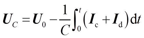
“全局常微分和代数微分方程”模块中涉及的电路方程为

 (1)
(1)
 (2)
(2)
 (3)
(3)
式中, 为线路电阻(取28 mΩ);
 为驱动线圈电流;
 为线路电感(取6.6 μH);
 为驱动线圈电阻;
 为驱动线圈电感;M为线圈和管件互感;
 为管件电流;
 为电容电压;
 为初始放电电压;C为放电电容(取320 μF);
 为线路电流;
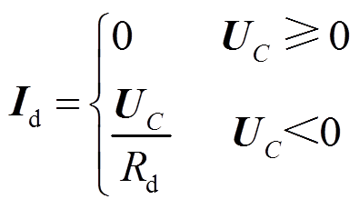
 为续流电阻(取200 mΩ)。将集磁器作为单匝线圈处理并设定其环向电流为零,可以近似模拟集磁器实际工作状态,实际上、下表面电流大小相等、方向相反。
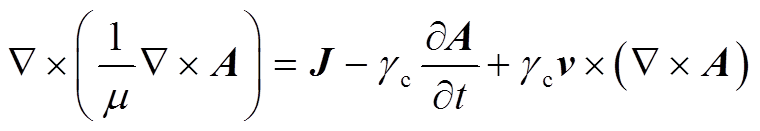
将“全局常微分和代数微分方程”模块中计算得到的线圈电流代入“磁场”模块,其中涉及的电磁方程为
 (4)
(4)
 (5)
(5)
 (6)
(6)
 (7)
(7)
式中,A为矢量磁动势;J为电流密度; 为介质电导率;
 为介质运动速度;B为磁感应强度;
 为管件上感应涡流;
 为管件电导率;
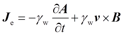
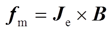
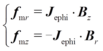
 为电磁力密度。对于二维轴对称结构,在极坐标下,电磁力密度可以进一步被分解为轴向分量和径向分量。管件轴向电磁力由径向磁感应强度和环向电流共同决定;径向电磁力由轴向磁感应强度和感应涡流共同决定。
 (8)
(8)
式中, 为感应涡流环向分量;
 和
和 分别为磁感应强度B的轴向和径向分量。
将“磁场”模块中计算得到的数据代入“固体力学”和“动网格”模块中进行进一步计算。本模型采用直径75 mm、壁厚2 mm、高度64.2 mm的AA6061-O铝合金管材,对比分析传统管件电磁胀形壁厚减薄量和轴向变形非均匀性。
AA6061-O铝合金管材的本构方程[21]为
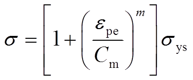 (9)
(9)
式中, 为应力;
为应力; 为管件塑性应变参数;m为应变率硬化参数(取0.25);
 为黏性参数(取6 500);
 为应变速率。
由于集磁器存在断缝,内外壁感应电流通过断缝形成回路,并且因为内外壁电流反向,新型集磁器内壁感应电流密度为负,而外壁感应电流密度则为正。通过仿真图5a可得,175 μs时线圈电流达到峰值,取峰值时刻数据对电流和磁场情况进行说明。双层凹型集磁器表面感应电流密度二维分布如图5b所示,集磁器内壁端部感应电流为正值,而内壁中部区域感应电流为负值,外壁感应电流主要集中在集磁器端部区域,而集磁器中间区域外壁感应电流密度则相对较小。管件上的感应涡流与新型集磁器感应电流所产生的磁场相互作用时,由于双层凹型集磁器外壁中间区域感应电流密度相对较小,从而管件中部受到的径向电磁力也相对较小,从而能够提高管件轴向均匀性。
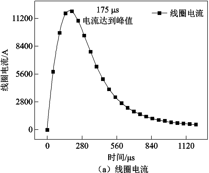
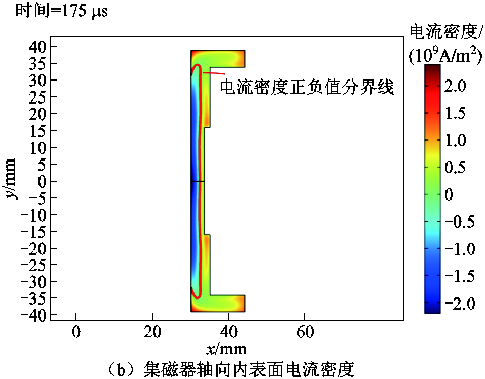
图5 线圈电流曲线及集磁器表面感应电流密度分布
Fig.5 Coil current curve and surface induced current density distribution of magnetic collector
由于在传统管件胀形系统中引入新型集磁器,相较于传统管件胀形而言,改变了管件成形区域磁场分布,从而进一步改变了管件成形区域力场分布。图6和图7分别为传统管件胀形与基于新型集磁器管件胀形在成形管件纵轴向中心线处径向磁感应强度与轴向电磁力分布。传统螺线管线圈管件径向磁感应强度在管件端部区域几乎为零,基于新型集磁器管件电磁胀形管件径向磁感应强度显著增加。径向磁感应强度的强弱决定管件轴向电磁力大小,当径向磁感应强度增加时,相应轴向电磁力同步增大,由仿真数据得出新型集磁器管件胀形端部区域轴向电磁力数值约为传统管件胀形端部区域轴向电磁力数值的3.68倍。
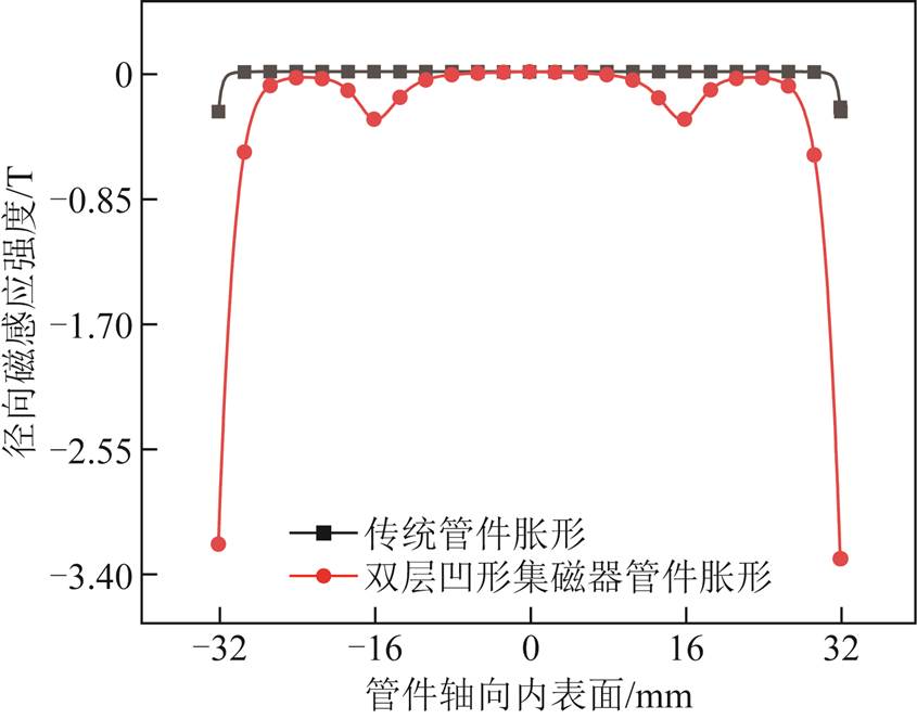
图6 管件径向磁感应强度
Fig.6 Radial flux density of tube
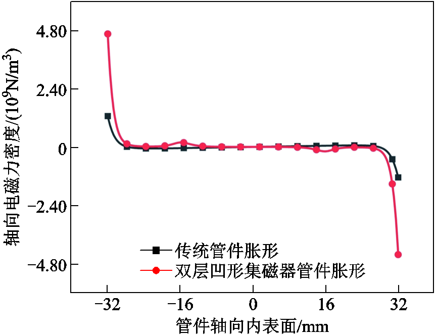
图7 管件轴向电磁力密度
Fig.7 Axial electromagnetic force density of the tube
根据上述仿真数值可得,管件端部轴向电磁力显著提升,进一步分析管件端部电磁力随时间的变化。由于胀形系统结构对称,为了简化计算量,只分析管件上表面轴向电磁力随时间的分布,结果如图8所示。管件上表面端部轴向电磁力为负值,即轴向电磁力方向为由上端部指向管件中部,随时间分布新型集磁器管件胀形轴向电磁力峰值约为传统管件胀形峰值的3.60倍。
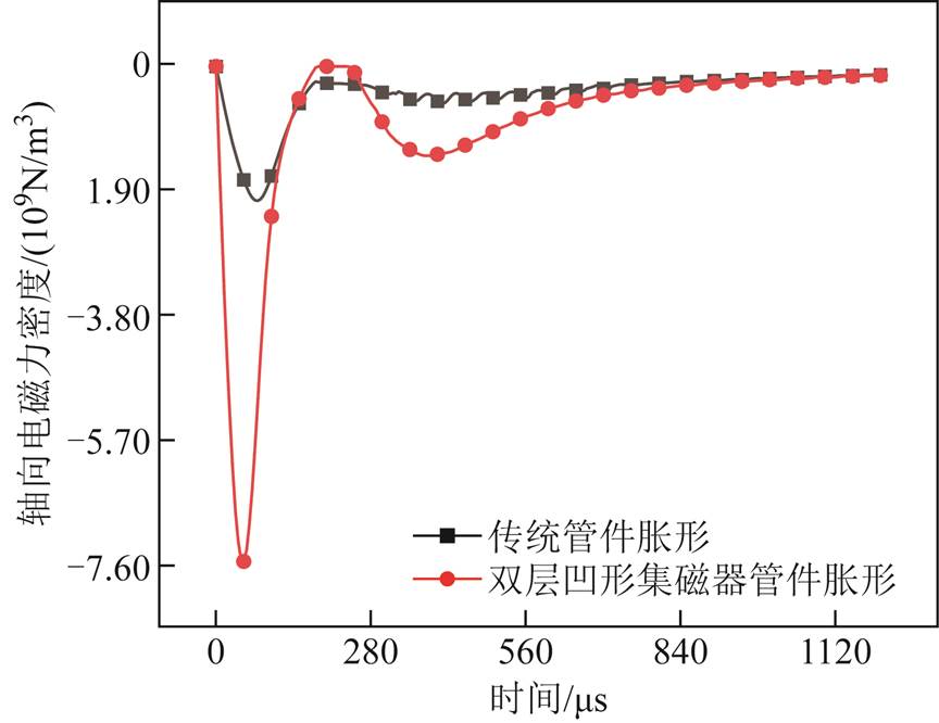
图8 管件轴向电磁力密度(管件上端部)
Fig.8 Axial electromagnetic force density of tubes (upper end of pipe fittings)
图9和图10分别为传统管件胀形和新型集磁器管件轴向磁感应强度分布和相应的径向电磁力分布规律。对于传统管件胀形,管件轴向内表面上轴向感应强度呈现凹形分布且管件中部磁感应强度最大;对于新型集磁器管件胀形,管件轴向内表面上轴向磁感应强度呈现凸形分布,并且由于新型集磁器凹陷部分增大了集磁器与管件之间的距离,因此管件中部磁感应强度相对较小。反映到径向电磁力,表现为传统管件胀形轴向内表面上的径向电磁力呈现凸形分布,且管件中部径向电磁力最大;新型集磁器管件胀形轴向内表面上的径向电磁力呈现凹形分布,且管件中部径向电磁力削弱。
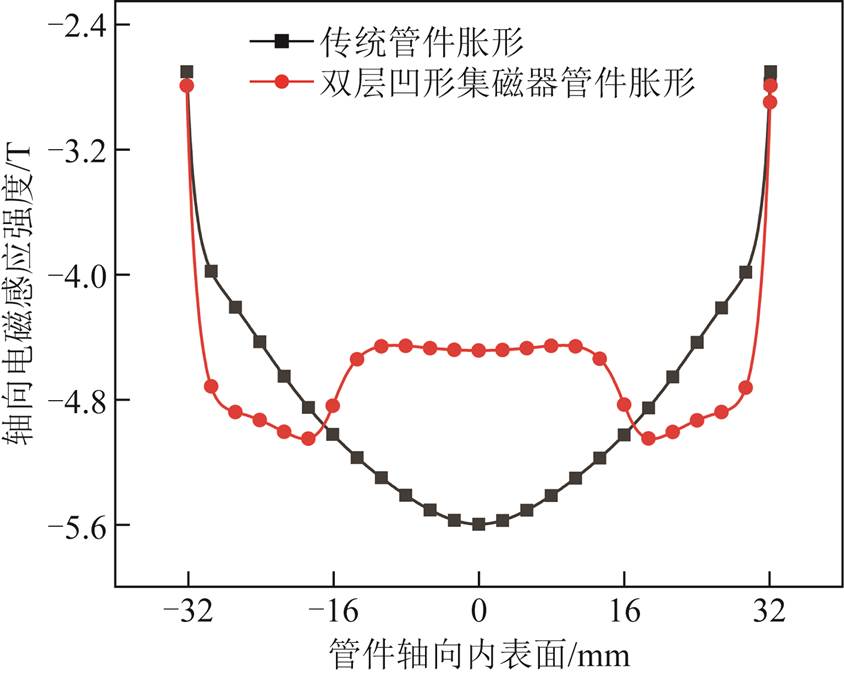
图9 管件轴向磁感应强度
Fig.9 Axial flux density of tube
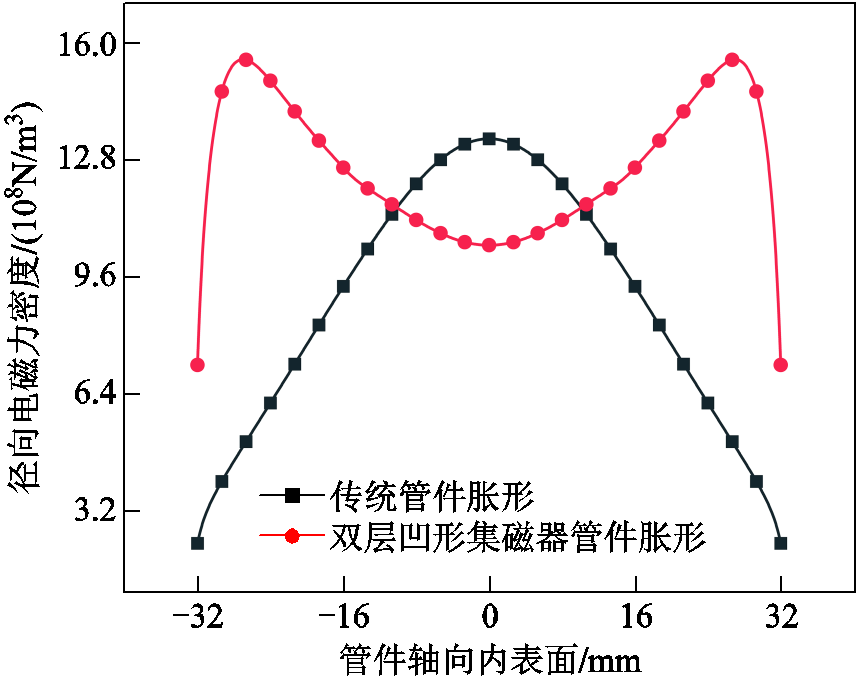
图10 管件径向电磁力密度
Fig.10 Radial electromagnetic force density of tube
本节对传统管件胀形和基于双层凹型集磁器管件胀形进行了对比分析。为了增强对比,成形管件高度和驱动线圈高度保持一致,且通过调节放电电压使得两类成形模式下,管件最大变形量保持基本一致。其中,螺线管线圈(传统)管件胀形时线圈电压设置为5.5 kV,新型集磁器管件胀形时线圈电压设置为6.5 kV。
图11给出了两类管件胀形系统下管件上端部材料轴向流动随成形时间的变化情况。可以看出,较传统管件胀形,双层凹形集磁器作用下,管件上端部材料流动效果更为显著。这主要是由于集磁器的引入使得管件所受到的轴向电磁力得到显著提升(见图8),促进了管件端部材料流动。管件端部材料流动的不同,进一步导致两类管件胀形系统下管件减薄特性存在显著差异,如图12所示。可以推出,管件壁厚减薄量由传统管件胀形的22.07%减小至新型集磁器管件胀形的8.30%,这也充分证明了新型集磁器可以有效地降低壁厚减薄。
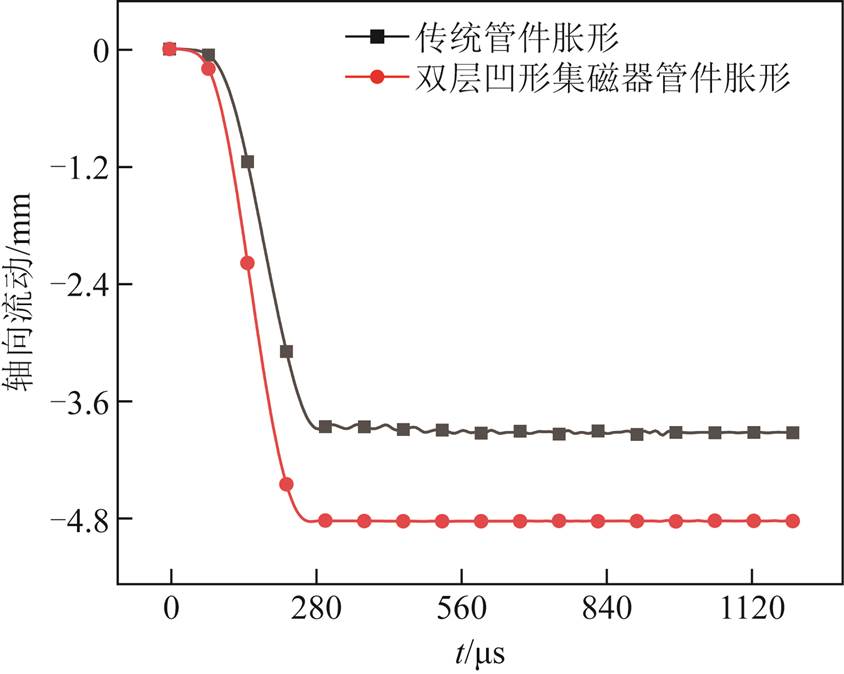
图11 管件端部材料轴向流动随时间的变化(管件上端部)
Fig.11 Material flow at the end of the tube (upper end of the tube)
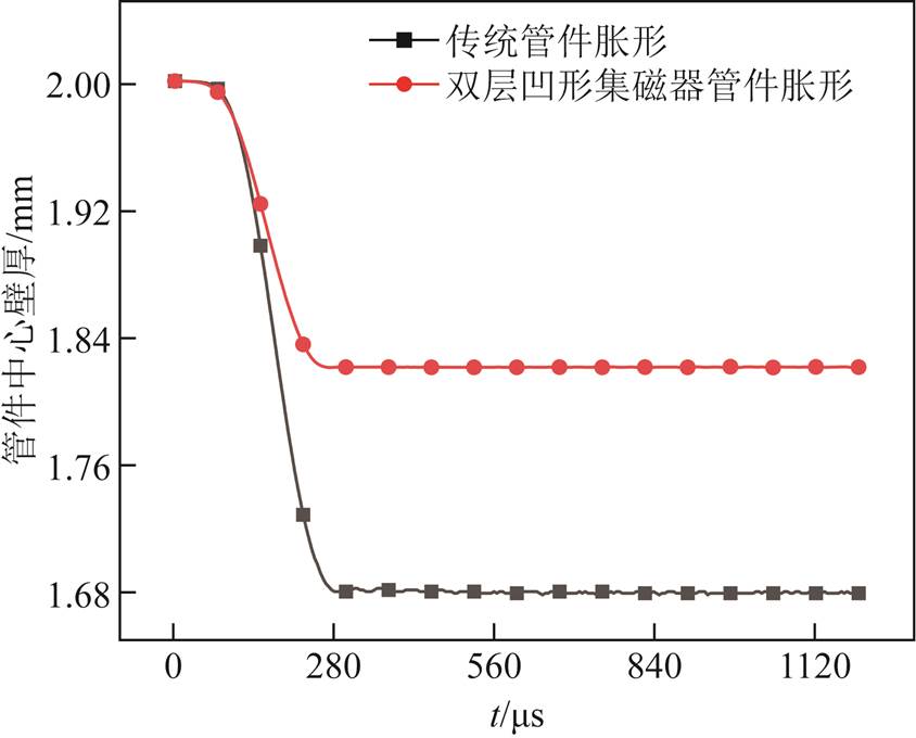
图12 管件中心壁厚随时间的变化
Fig.12 Tube center wall thickness
同时,为了验证新型集磁器是否能够有效解决传统管件轴向变形非均匀问题,对两类管件胀形系统下管件的变形过程及形貌进行了进一步分析。图13给出了胀形过程中管件内表面径向位移的变化。可以看出,传统管件胀形过程中管件形貌一直呈现凸形结构;而在双层凹形集磁器管件胀形系统中,由于管件中心区域成形力较小(见图10),因此在成形开始时间段呈现凹型形貌,但随着变形过程的推进,在两边较大变形区域的带动下,最终形成较为均匀的成形区域。
图14给出了两类管件胀形系统下管件的最终成形轮廓。可以看出,对于电磁力呈现“凸形”分布的螺线管线圈而言,管件存在明显的变形不均匀现象;对于电磁力呈现“凹形”分布的新型集磁器来说,管件中部变形量明显减小,呈现均匀变形特征。为了进行定量比较,使用Dr来比较二者管件变形均匀度。其中,Dr定义为管件轴向上能达到最大径向胀形量90%的区域。对于传统管件胀形,Dr=27.8 mm;当采用双层凹形集磁器时,Dr=64.2 mm。通过数据可以直观地看出,双层凹形集磁器的引入,可以显著改善管件轴向变形不均匀问题。
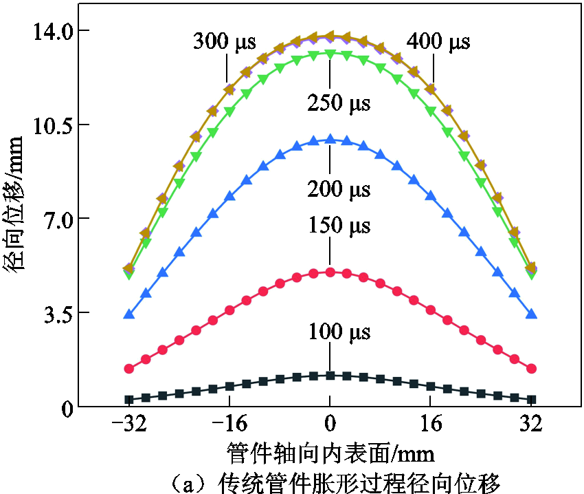
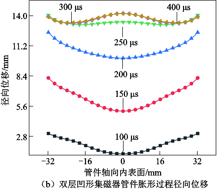
图13 传统管件胀形和双层凹形集磁器胀形过程中径向位移的变化
Fig.13 Bulging changes in the traditional tube bulging and double-layer concave magnetic collector bulging process

图14 传统管件和双层凹形集磁器管件胀形的最终轮廓
Fig.14 bulging contour comparison of traditional tube and double - layer concave magnetic collector tube
在前文模型构建基础上,进一步探究新型集磁器内凹高度对管件胀形影响。在保持驱动线圈、成形管件以及初始放电电压5.5 kV一致的前提下,通过改变新型集磁器内凹高度,以新型集磁器凹陷8 mm为起点,探究了不同集磁器凹陷高度下(16 mm、32 mm、64 mm)管件径、轴向电磁力特性以及轴向变形均匀性和壁厚减薄的变化规律。
图15给出了不同集磁器凹陷高度下管件变形后的径向位移。可以看出,相较于传统管件胀形,引入具有不同凹陷高度的集磁器,管件胀形轴向不均匀性问题均可得到显著改善;但随着新型集磁器凹陷高度不断增加,管件整体径向位移呈下降趋势。
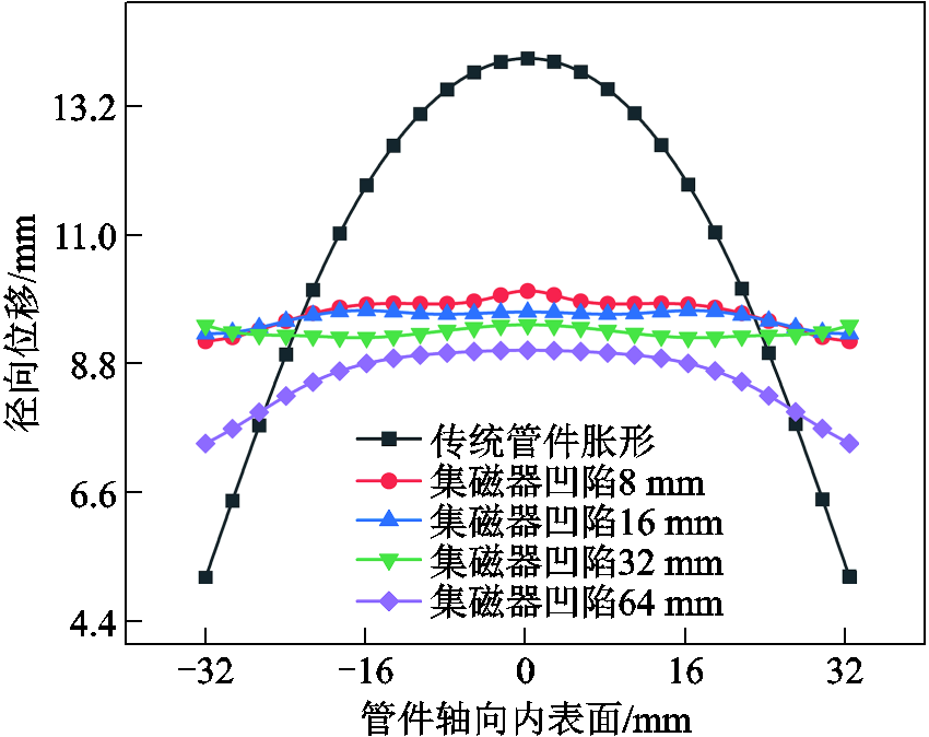
图15 新型集磁器凹陷高度对管件胀形径向位移的影响
Fig.15 Effect of concave height of new magnetic collector on radial displacement of tube bulging
此外,从仿真数据可以看出,当集磁器凹陷达到32 mm时,管件胀形已具有很好的均匀性,进一步增大集磁器内凹高度,管件轴向均匀性反而变差,但是总体仍显著优于传统管件胀形。图16给出了不同集磁器凹陷高度下管件中心壁厚的变化情况,表明增大集磁器内凹高度有助于增大管件壁厚。进一步,图17给出了不同集磁器凹陷高度下管件端部材料流动和壁厚减薄量的变化情况。可以看出,随着引入的集磁器凹陷高度不断增加,管件壁厚减薄量呈减小趋势,与图16管件中心壁厚变化情况相对应;但是集磁器凹陷高度达到32 mm时,管件端部材料流动反而减小,这是因为集磁器凹陷过大时,管件变形量减小(见图15),从而导致管件端部材料流动相应减少。
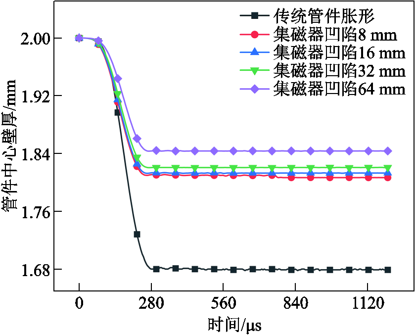
图16 新型集磁器内壁凹陷高度对管件中心壁厚的影响
Fig.16 Influence of inner wall height of new magnetic collector on wall thickness of tube center
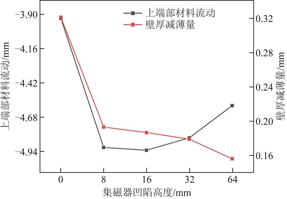
图17 管件上端部材料流动与壁厚减薄量对比
Fig.17 Comparison of material flow and wall thickness reduction at the end of pipe fittings
为了解释上述管件轴向变形均匀性和壁厚减薄的变化特性,进一步对管件所受径向电磁力和轴向电磁力进行分析。图18给出了不同集磁器凹陷高度下管件所受的径向电磁力特性。可以看出,随着集磁器凹陷高度的增加,管件所受径向电磁力呈减小趋势,这很好地解释了图15中随着集磁器凹陷高度不断增加径向位移却逐步减小的现象。对于图15中出现集磁器凹陷超过32 mm之后,管件均匀性变差的现象,这与管件端部所受轴向电磁力特性有关。图19给出了不同集磁器凹陷高度下管件所受的轴向电磁力特性。一方面可以看出,引入集磁器后管件上端部受到的轴向电磁力均向下,这有助于促进管件轴向流动而抑制管件壁厚减薄;另一方面可以看出,随着集磁器凹陷高度的增加,与径向电磁力逐渐变小不同,管件端部所受轴向电磁力增大,这也使得当凹陷高度过大时,管件轴向电磁力对管件变形行为的影响较大,易在端部较大轴向电磁力的作用下形成凸形弯曲特征,造成轴向变形均匀性一定程度的降低。

图18 新型集磁器凹陷高度对管件径向电磁力的影响
Fig.18 The effect of the new magnet collector concave height on the radial electromagnetic force of the tubing
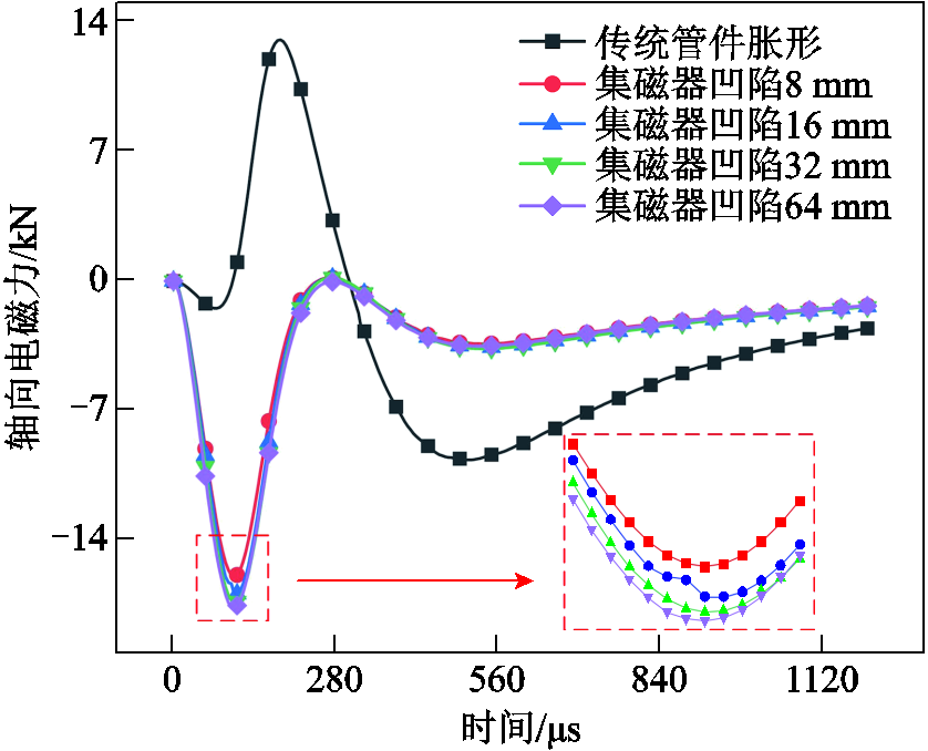
图19 新型集磁器凹陷高度对轴向电磁力的影响
Fig.19 The effect of the concave height of the new magnet collector on the axial electromagnetic force
针对传统螺线管线圈管件胀形中存在的管件壁厚减薄和轴向变形非均匀的问题,本文提出基于单驱动线圈和双层凹型集磁器管件电磁胀形方案,并探究了集磁器内凹高度对管件胀形特性的影响。研究表明,通过在线圈和管件之间引入该类新型集磁器,一方面管件端部可形成显著轴向压缩电磁力,促进端部材料流动,进而可抑制成形过程中管件壁厚减薄;另一方面,凹型集磁器结构下管件中部区域的径向电磁力变小,可避免传统管件成形中出现的“两端小,中间大”现象,显著提升变形均匀度。与此同时,研究指出增大集磁器内凹高度有助于提升管件壁厚减薄抑制效果,在一定范围内能够增大成形管件轴向均匀度,但是随着集磁器内凹高度不断增加,成形管件轴向均匀度反而会略微降低,但是仍显著优于传统管件胀形。值得一提的是,该方案采用单个驱动线圈,工装结构非常简单,集磁器结构参数可以根据具体的成形需求进行设计和调整。后续将构建相关实验系统,从实验层面进一步验证所提新型管件电磁胀形方法的实际效果。
参考文献
[1] Zhou Bo, Liu Bo, Zhang Shengen. The advancement of 7XXX series aluminum alloys for aircraft structures: a review[J]. Metals, 2021, 11(5): 718.
[2] Psyk V, Risch D, Kinsey B L, et al. Electromagnetic forming—a review[J]. Journal of Materials Processing Technology, 2011, 211(5): 787-829.
[3] Li Xiaoxiang, Cao Quanliang, Lai Zhipeng, et al. Bulging behavior of metallic tubes during the electromagnetic forming process in the presence of a background magnetic field[J]. Journal of Materials Processing Technology, 2020, 276: 116411.
[4] Ouyang Shaowei, Li Changxing, Du Limeng, et al. Electromagnetic forming of aluminum alloy sheet metal utilizing a low-frequency discharge: a new method for attractive forming[J]. Journal of Materials Processing Technology, 2021, 291: 117001.
[5] 邱立, 李彦涛, 苏攀, 等. 电磁成形中电磁技术问题研究进展[J]. 电工技术学报, 2019, 34(11): 2247-2259. Qiu Li, Li Yantao, Su Pan, et al. Research on electromagnetic problems in electromagnetic forming process[J]. Transactions of China Electrotechnical Society, 2019, 34(11): 2247-2259.
[6] Tang Yinghao, Li Xiaoxiang, Zhang Yi, et al. Design of pulsed magnet for adjusting the residual stress field in large-size aluminum alloy rings[J]. IEEE Transactions on Applied Superconductivity, 2022, 32(6): 1-5.
[7] Pawar S, Kore S D. Electromagnetic forming and perforation of Al tubes[J].Journal of Mechanical Science and Technology, 2019, 33(12): 5999-6007.
[8] Qiu Li, Yu Yijie, Wang Ziwei, et al. Analysis of electromagnetic force and deformation behavior in electromagnetic forming with different coil systems[J]. International Journal of Applied Electromagnetics and Mechanics, 2018, 57(3): 337-345.
[9] Li Zhangzhe, Han Xiaotao, Cao Quanliang, et al. Design, fabrication, and test of a high-strength uniform pressure actuator[J]. IEEE Transactions on Applied Superconductivity, 2016, 26(4): 1-5.
[10] Li Xiaoxiang, Cao Quanliang, Lai Zhipeng, et al. Bulging behavior of metallic tubes during the electromagnetic forming process in the presence of a background magnetic field[J]. Journal of Materials Processing Technology, 2020, 276: 116411.
[11] 熊奇, 周丽君, 杨猛, 等. 单脉冲电磁成形中洛伦兹力在时间上的双向竞争关系及其对成形效果的影响[J]. 电工技术学报, 2022, 37(14): 3453-3463. Xiong Qi, Zhou Lijun, Yang Meng, et al. The two-way competitive relationship of Lorentz force in time in single pulse electromagnetic forming and its influence on forming effect[J]. Transactions of China Electrotechnical Society, 2022, 37(14): 3453-3463
[12] Yu Haiping, Xu Zhidan, Fan Zhisong, et al. Mechanical property and microstructure of aluminum alloy-steel tubes joint by magnetic pulse welding[J]. Materials Science and Engineering: A, 2013, 561: 259-265.
[13] 熊奇, 朱鑫辉, 赵翔, 等. AZ31镁合金管件电磁吸引式成形动态特性研究[J]. 电工技术学报, 2023, 38(10): 2577-2588, 2636. Xiong Qi, Zhu Xinhui, Zhao Xiang, et al. Research of dynamic characteristics in electromagnetic attraction forming of AZ31 magnesium alloy tube[J]. Transactions of China Electrotechnical Society, 2023, 38(10): 2577-2588, 2636.
[14] 张望, 王于東, 李彦涛, 等. 基于双向电磁力加载的管件电磁翻边理论与实验[J]. 电工技术学报, 2021, 36(14): 2904-2911. Zhang Wang, Wang Yudong, Li Yantao, et al. Theory and experiment of tube electromagnetic flanging based on bidirectional electromagnetic force loading[J]. Transactions of China Electrotechnical Society, 2021, 36(14): 2904-2911.
[15] Ouyang Shaowei, Wang Chen, Li Changxing, et al. Improving the uniformity and controllability of tube deformation via a three-coil forming system[J].The International Journal of Advanced Manufacturing Technology, 2021, 114(5/6): 1533-1544.
[16] Qiu Li, Li Yantao, Yu Yijie, et al. Electromagnetic force distribution and deformation homogeneity of electromagnetic tube expansion with a new concave coil structure[J]. IEEE Access, 2019, 7: 117107-117114.
[17] Zhang Xiao, Ouyang Shaowei, Li Xiaoxiang, et al. Effect of pulse width of middle-coil current on deformation behavior in electromagnetic tube forming under two-stage coils system[J].The International Journal of Advanced Manufacturing Technology, 2020, 110(5/6): 1139-1152.
[18] 邱立, 杨新森, 常鹏, 等. 双线圈轴向压缩式管件电磁胀形电磁力分布规律与管件成形性能研究[J]. 电工技术学报, 2019, 34(14): 2855-2862.Qiu Li, Yang Xinsen, Chang Peng, et al. Electromagnetic force distribution and forming performance in electromagnetic tube expansion process with two coils[J]. Transactions of China Electrotechnical Society, 2019, 34(14): 2855-2862.
[19] 邱立, 余一杰, 聂小鹏, 等. 管件电磁胀形过程中的材料变形性能问题与电磁力加载方案[J]. 电工技术学报, 2019, 34(2): 212-218. Qiu Li, Yu Yijie, Nie Xiaopeng, et al. Study on material deformation performance and electromagnetic force loading in electromagnetic tube expansion process[J]. Transactions of China Electrotechnical Society, 2019, 34(2): 212-218.
[20] Cao Quanliang, Li Liang, Lai Zhipeng, et al. Dynamic analysis of electromagnetic sheet metal forming process using finite element method[J]. The International Journal of Advanced Manufacturing Technology, 2014, 74(1): 361-368.
[21] Ouyang Shaowei, Li Xiaoxiang, Li Changxing, et al. Investigation of the electromagnetic attractive forming utilizing a dual-coil system for tube bulging[J]. Journal of Manufacturing Processes, 2020, 49: 102-115.
Abstract Electromagnetic forming technology has significant advantages over mechanical processing technology in the processing of light alloy materials and is an important way to realize energy saving and emission reduction in aerospace, automobile manufacturing and other fields. However, the traditional electromagnetic tube expansion process has the defects of serious wall thinning and uneven axial deformation. Based on the traditional electromagnetic tube expansion system, this paper proposed a novel type of double-layer field shaper to regulate the distribution of magnetic field and electromagnetic force.
The new field shaper structure can adjust the radial electromagnetic force distribution characteristic from “small at the ends, large in the middle” mode to “large at the ends, small in the middle” mode. And the smaller axial electromagnetic force at the end of the tube can be adjusted to a larger electromagnetic force. The adjustment of the radial electromagnetic force field distribution can weaken the radial electromagnetic force in the middle of the formed tube, thus changing the deformation shape of the tube and improving the characteristics of uneven axial deformation of the tube; the adjustment of the axial electromagnetic force field distribution can promote the flow of the material at the end of the tube to the middle area, compensating for the reduction of the wall thickness of the tube due to radial expansion, thus suppressing the wall thickness thinning phenomenon of the tube. To verify the effectiveness of the double-layer field shaper, the finite element model of electromagnetic coupling structure for the electromagnetic tube expansion system was established by using COMSOL software. In this paper, the change laws of the key physical quantities, such as, the electromagnetic force distribution, the axial deformation uniformity and the wall thickness thinning amount were compared and studied under the condition with or without field shaper. On this basis, the influence of the inner cavity depth of the field shaper on the forming effect of tubes was further explored.
The simulation results show that the new field shaper structure improves the axial uniformity by 2.31 times compared with the traditional expansion process, and reduces the wall thickness thinning from 22.07% to 8.30%. The effectiveness of the new field shaper structure in improving the wall thickness thinning and uneven axial deformation of tubes was verified. In addition, increasing the concave height of field shaper is helpful to restrain the wall thinning of tubes, and increase the axial uniformity in a certain range. However, with the further increase of the concave height of field shaper, the radial and axial force fields in the tube forming area are further regulated, the axial uniformity will slightly decrease, but it is still significantly better than the traditional tube expansion effect. It is worth mentioning that the bulging method proposed in this paper adopts single drive coil with simple structure and convenient toolingcompared to multi-coil electromagnetic forming systems. The actual effect of the bulging method will be further verified from the experimental level in the future.
keywords:Electromagnetic forming, electromagnetic force, magneticfield shaper, deformation behavior
DOI: 10.19595/j.cnki.1000-6753.tces.222324
中图分类号:TM154
国家自然科学基金资助项目(51877122)。
收稿日期 2022-12-12
改稿日期 2023-04-01
邵子豪 男,1999年生,硕士研究生,研究方向为电磁成形。E-mail:shaozihao1999@163.com
邱 立 男,1984年生,博士,副教授,研究方向为电磁成形。E-mail:Doctor_QiuL@163.com(通信作者)
(编辑 郭丽军)