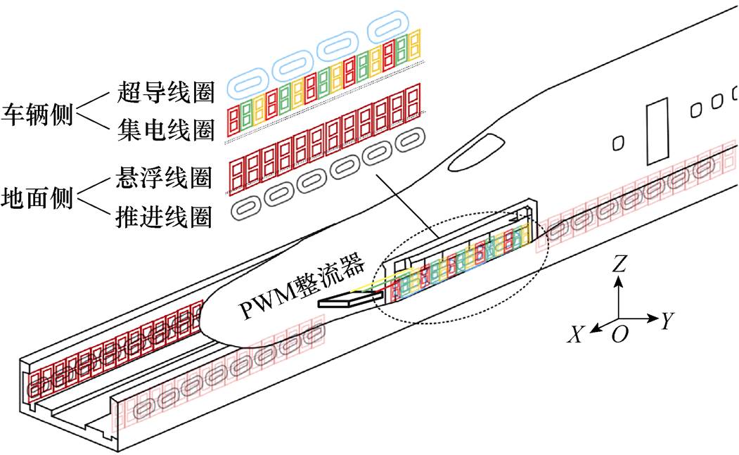
图1 电动磁浮系统结构示意图
Fig.1 Structure diagram of EDS maglev system
摘要 为实现电动磁浮列车低速运行阶段无接触辅助供电,同时尽可能减轻耦合机构重量,并保障供电系统平稳输出,该文设计了一种利用磁浮系统原有线圈作为耦合机构的感应式电能传输(IPT)系统,通过线圈与电路结构重构,以列车低速运行阶段空置的悬浮线圈与集电线圈作为能量传输通道。由于不需额外安装能量传输线圈,所提出的IPT系统对磁浮列车自重影响小,且耦合机构在移动过程中具有互感恒定的特性,结合LCC-S谐振补偿电路,IPT系统在列车移动过程中与负载变化过程中均能保持稳压输出。为验证所提方案的可行性和有效性,搭建了1 kW的原理样机,在移动供电过程中,IPT系统输出电压波动仅1.51%,输出功率在300~1 000 W范围变化时,输出电压波动为4.42%,系统整体效率为83.75%~86.61%。
关键词:电动磁浮 感应式电能传输 线圈复用 平稳输出
电动磁浮(Electrodynamic Suspension, EDS)列车[1-3]的集电系统[4-6]是保障磁浮列车高速运行阶段车载设备稳定运行的能量源泉。其依靠集电线圈从悬浮间隙中的谐波行波磁场中拾取能量,具有安全、可靠、无噪声、无磨损等优点。然而,集电系统在低速运行阶段供电能力不足[7-8],车载设备用电需通过额外的接触受流装置提供,不仅存在集电靴磨损、噪声大等问题,而且在高寒覆冰等恶劣天气条件下受流质量差[9],严重影响电动磁浮列车运行的安全性与可靠性。
感应式电能传输(Inductive Power Transfer, IPT)技术[10-13]在近年来得到迅速发展,该技术以高频磁场作为能量传输介质,可实现电能无物理接触传输,能够有效避免上述接触式供电的弊端。近年来在国内外已有若干条采用IPT系统的磁浮列车试验线投入运行[14-15]。然而,磁浮列车IPT系统往往需要在车辆侧额外加装大重量的接收机构,对磁浮系统运营经济性的影响难以忽视,因此非常有必要针对磁浮列车应用场景,探索新型的轻量化IPT系统。
对IPT系统耦合机构进行优化设计,进而提高其自身功率密度是一种可行思路。文献[16]采用多目标优化方法对接收线圈结构及导磁材料排布方式进行设计,但受限于材料性能,该方法优化效果基本已达上限。文献[17]在研究中发现,传统的电动磁浮系统结构如图1所示,需通过多种单一功能的线圈实现推进、悬浮等功能,若采用线圈复用技术,将多种功能集成在一种线圈中,则可以大幅简化系统结构。
上述方法为进一步减轻IPT系统重量带来了新思路,文献[18]提出了一种以电动磁浮列车的集电线圈作为接收线圈的集成式IPT系统,不需在列车上额外安装设备,完全避免了对列车自重的影响。但由于电动磁浮系统侧面悬浮间隙限制严格,IPT系统的能量发射线圈占用了悬浮线圈的安装空间。因此布置了该型IPT系统的路段在为低速运行的列车提供无线电能传输的同时失去了供列车高速通过的能力。

图1 电动磁浮系统结构示意图
Fig.1 Structure diagram of EDS maglev system
另外,相比于静态IPT系统,动态IPT系统原副边线圈互感随列车位移存在周期性大幅波动,降低系统输出稳定性[19]。耦合机构优化设计是提升动态IPT系统供电稳定性的主要方法之一,其原理为设计线圈的结构[20]或布局[21]以塑造更为均匀的磁场。然而,在复用电动磁浮系统原有线圈进行能量传输的前提下,耦合机构结构改变影响列车原有功能,因此现有优化方法无法直接应用。文献[22]采用了一种双接收线圈结构,通过两个互感波动相反的接收线圈串联,使得整体接收线圈交链磁场保持均匀,功率输出稳定。由于集电系统的多接收线圈结构,各接收线圈与原边线圈存在的互感波动可采用类似方法抑制。
综上所述,为进一步满足电动磁浮列车IPT系统的轻量化设计需求,本文设计了一种基于可重构线圈结构与电路拓扑的集成式IPT系统。在列车低速运行时,复用车辆侧集电线圈与电路进行高频无线电能传输,避免了额外安装大重量的接收机构。同时,在列车高速运行时,线圈与电路能够重构为传统结构,避免影响磁浮系统原有功能。并且,利用多线圈串联的绕组结构设计,使各接收线圈与整体发射线圈的互感波动相互抵消,副边接收线圈与原边发射线圈的互感能够保持近似恒定,结合基于LCC-S谐振补偿网络的系统电路拓扑,所提集成式IPT系统能够在不同位置与负载条件下均保持稳压输出。
图2为所提电动磁浮列车IPT系统示意图,在地面侧,悬浮线圈(IPT系统中复用为发射线圈)在列车低速(≤150 km/h)[2]运行区间内沿轨道行进方向无限延伸铺设。发射线圈极距为t1,上、下回路高度均为b1,长度为a1。设计每14个发射线圈为一组,每组发射线圈通过直流电源、高频逆变器、补偿网络向其中通入高频电流,各组发射线圈电流幅值、频率、相位一致。
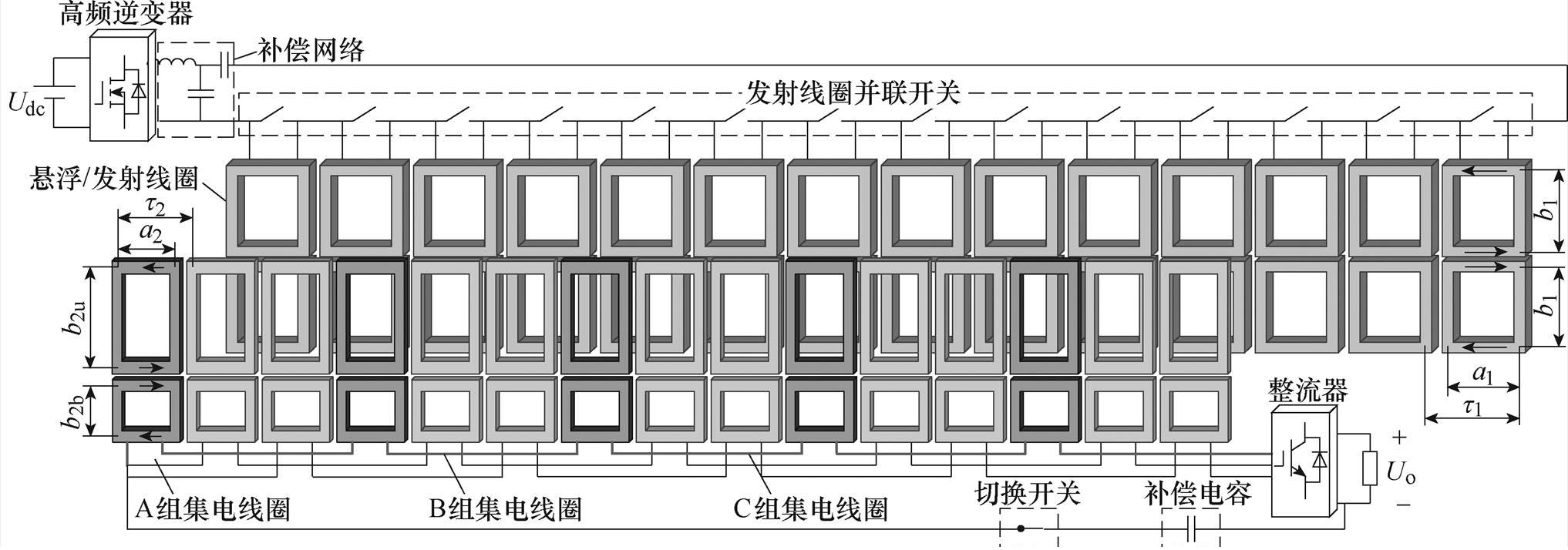
图2 IPT系统示意图
Fig.2 Schematic diagram of the IPT system
在车辆侧,悬浮架单侧排列有15个集电线圈(在IPT系统中作为接收线圈),极距为t2,由上、下两个回路组成8字型结构,上回路高度为b2u,下回路高度为b2b,线圈长度为a2。15个集电线圈分属ABC三组,每组包含5个相互串联的线圈。图3为IPT系统电路,KP1~KP14为各发射线圈并联开关,KS为车辆侧切换开关,CS为集中补偿电容,4个功率MOSFET(S1~S4)构成高频逆变器,LP1~LP14为各发射线圈电感。各个接收线圈与整体发射线圈间互感分别为Ma1~Ma5、Mb1~Mb5、Mc1~Mc5,各个接收线圈自感分别为La1~La5、Lb1~Lb5、Lc1~Lc5,La、Lb、Lc为各组接收绕组电感,6个IGBT(Q1~Q6)构成整流桥,电阻RL为列车车载设备等效负载。

图3 IPT系统电路
Fig.3 Circuit diagram of the IPT system
在低速运行阶段,电动磁浮列车依靠支撑轮在轨道上接触运行,8字型结构的悬浮线圈与跑道型结构的超导线圈近似解耦。此时悬浮线圈与集电系统电路均处于无电流的空置状态,同时断开开关KP1~KP14,高频逆变器通过补偿网络向悬浮线圈中注入恒定的高频电流iP,以其作为能量发射线圈在悬浮间隙中激发高频磁场。IPT系统简化电路如图4a所示,相较于传统的电动磁浮列车集电系统电路[23],图中额外增添的元件包括开关KS与电容CS。
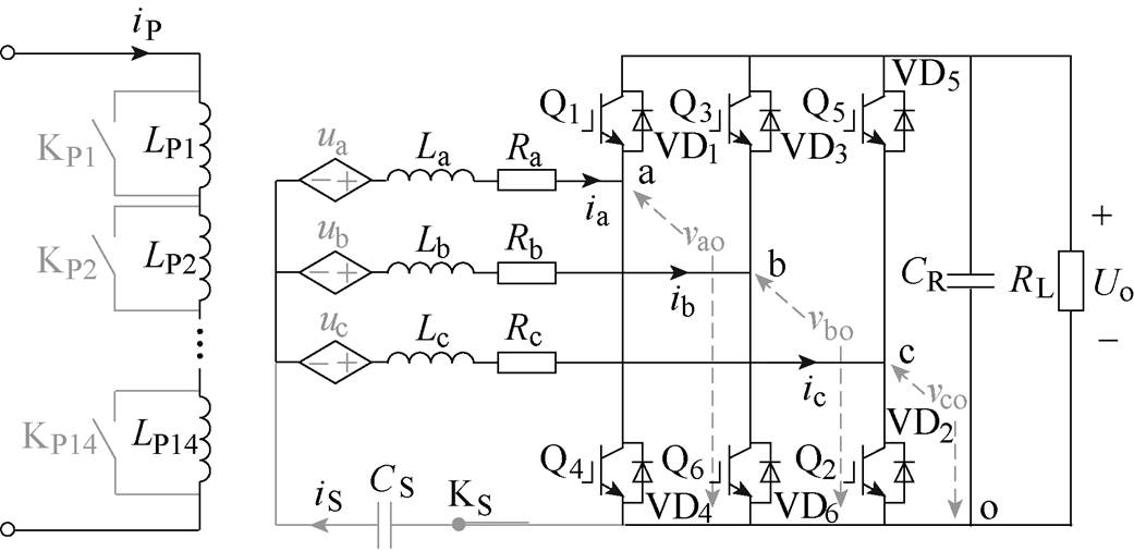
(a)低速运行时IPT系统简化电路
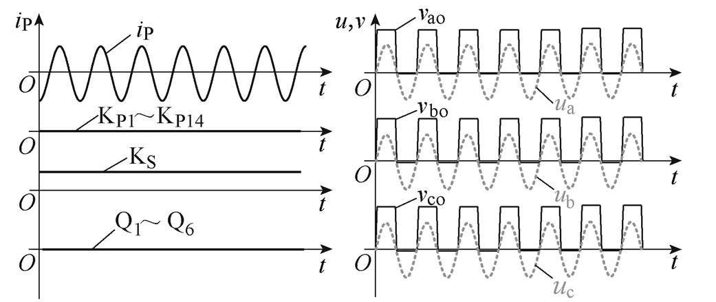
(b)iP与开关信号 (c)ua、ub、uc波形
图4 低速工况IPT系统电路及波形
Fig.4 Circuit diagram and waveforms of the IPT system at low speed
当各接收绕组与发射线圈互感相同时,接收绕组感应电压ua、ub、uc幅值、相位相同,波形如图4c所示。此时,若无开关KS与电容CS构成回路,各接收绕组感应电压相位相同、幅值一致,三组星形联结的接收绕组无法对外输出电流,IPT系统无法正常工作。为此,利用绕组星形联结中点与直流母线负极间增添的开关KS切换电路,使电路变更为三相四线制,为高频电流提供通路。同时,为补偿三组绕组消耗的无功功率,电容CS通过开关KS串联接入电路中。Q1~Q6不施加控制信号,其反并联二极管VD1~VD6构成三桥臂倍压整流器进行整流。并且,与悬浮线圈-超导线圈耦合关系相同,8字形结构的集电线圈也能够实现与超导线圈的解耦,所提IPT系统在复用悬浮线圈与集电线圈作为耦合机构进行无线电能传输的同时,不影响超导线圈运行。
传统的电动磁浮列车加速达到起浮速度(150 km/h)后,将会收起支撑轮,行进的超导磁场切割悬浮线圈产生感应电流,并进一步在气隙中激发感应磁场,超导磁体与该磁场的基波分量相互作用,使列车获得足够的悬浮力。上述过程的实现依赖首尾闭合的悬浮线圈,图4a中首尾断开、依次串联的悬浮线圈LP1~LP14显然无法按照上述原理工作。
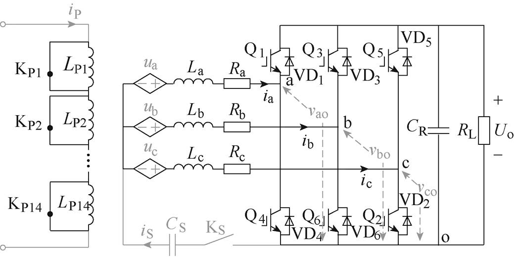
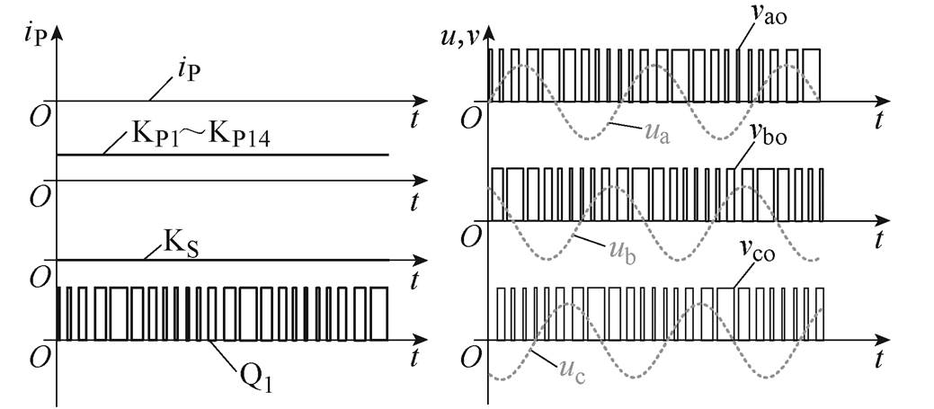
为避免IPT系统阻碍电动磁浮系统高速运行工况,需要关闭IPT系统并将悬浮线圈与车辆侧电路切换回传统结构。变更各开关、IGBT控制信号如图5b所示,首先关闭IPT系统的高频逆变器,停止向各个悬浮线圈中注入高频电流,然后同时闭合各个悬浮线圈对应并联开关(KP1~KP14),各个悬浮线圈分别通过各自的并联开关恢复为首尾闭合的零磁通线圈。同时在车辆侧,断开开关KS以切除补偿电容CS,各个开关均在电路无电流时切换,避免了电路暂态过程对供电稳定性的影响。
(a)高速运行时IPT系统简化电路
(b)iP与开关信号 (c)ua、ub、uc波形
图5 高速工况IPT系统电路及波形
Fig.5 Circuit diagram and waveforms of the IPT system at high speed
电动磁浮列车高速运行时,系统电路切换如图5a所示。IPT系统关闭后,闭合的悬浮线圈由超导磁场激发低频感应电流,进而在气隙中激发感应磁场,其谐波分量在车辆侧的ABC三相绕组中感应出图5c所示的三相对称电压ua、ub、uc。Q1~Q6构成三相PWM整流器进行整流、升压与无功功率补偿,电路结构及控制方式与传统集电系统相同[6]。
考虑电动磁浮列车低速运行时受轨道限制带来的准一维运动特征[24],对耦合机构分析时仅考虑沿列车行进方向(设为X轴正向)的互感变化,图6为本文所设计的耦合机构示意图。图中,lg为原边和副边之间的距离。

图6 耦合机构示意图
Fig.6 Diagram of the coupler
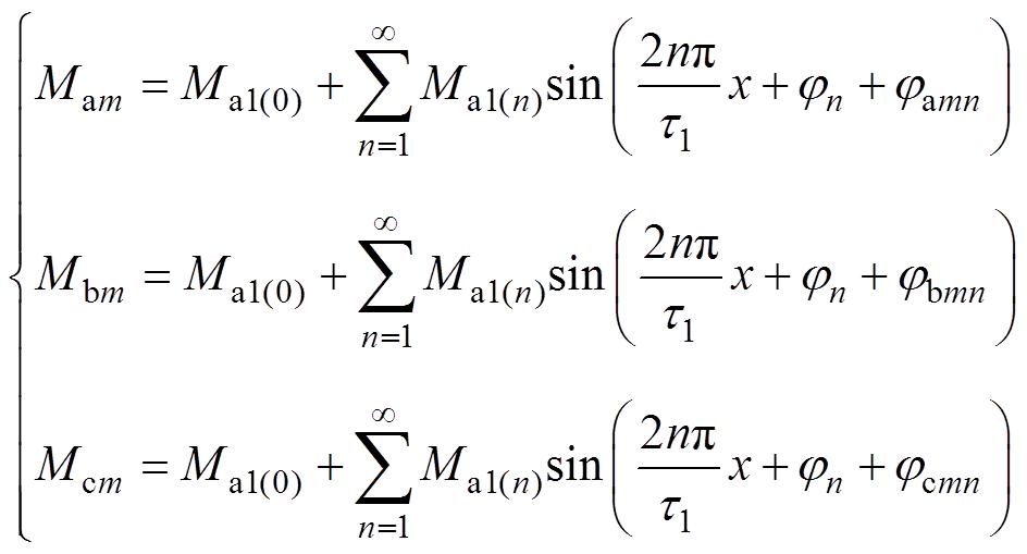
由于发射线圈在列车低速运行区间内沿轨道行进方向无限延伸铺设,且各发射线圈结构与电流相同。当ABC三组接收绕组中单个线圈沿X轴正向位移量为x时,其与整体发射线圈的互感Mam、Mbm、Mcm(m=1, 2, 3, 4, 5)随x以t1为周期的周期性变化,可通过傅里叶级数表示为
 (1)
(1)
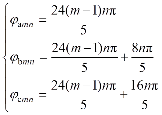
式中,n为正整数;式(1)说明互感Mam可表示为由常数Ma1(0)与周期为t1、t1/2、…、t1/n的各次正弦分量相加的函数;jn为各次正弦分量对应初始相位。由于各接收线圈参数相同,且各线圈距离为t2的整数倍,因此Mam、Mbm、Mcm中各次正弦谐波项有效值相同,仅相位存在差异。由于发射与接收线圈极距比满足4t1=5t2,因此有
 (2)
(2)
定义Ma为A组绕组与整体发射线圈互感,设计A组绕组各线圈串联连接,忽略绕组内各个线圈间互感,有
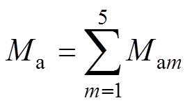 (3)
(3)
同理,定义Mb、Mc分别为B组和C组绕组与整体发射线圈之间的互感,LP为发射线圈LP1~LP14串联后的总自感。由式(1)~式(3)可得Ma、Mb、Mc满足
 (4)
(4)
式(4)表示在移动供电过程中,三组接收绕组与发射线圈互感始终保持相同,由式(5)可知,各接收绕组感应电压可保持均衡。
 (5)
(5)
对于互感Ma1~Ma5,由于各次谐波在不同接收线圈中相位jamn不同,互感Ma1~Ma5相加获得的互感Ma中除周期为t1/5、t1/10、…的其他次谐波可由矢量叠加原理而完全抵消,联立式(1)~式(3)求解互感Ma为
 (6)
(6)
式(6)表示,虽然在移动过程中,单个接收线圈与整体发射线圈间互感存在较大波动,但由于一组接收绕组由5个接收线圈串联构成,各个接收线圈互感相互叠加,使单个接收绕组与整体发射线圈互感的波动得到大幅抑制,甚至近似保持为恒定值。
为验证上述理论分析结果,按表1参数在Ansys/Maxwell有限元分析软件中搭建IPT系统耦合机构仿真模型。仿真获得互感随位移x的变化曲线如图7所示。定义互感波动率为
 (7)
(7)
表1 IPT系统耦合机构参数
Tab.1 Parameters of the IPT coupler (单位: mm)

参 数数 值 a2245 a1350 b2u435 b2b245 b1340 t1450 t2360 lg110
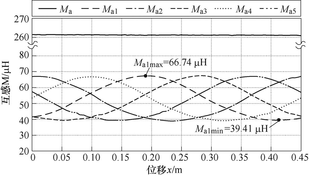
图7 互感随位移x变换曲线
Fig.7 Mutual inductance with displacement x
计算可得单个接收线圈的互感波动率为25.75%,单组接收绕组的互感波动率仅为0.15%。发射线圈与A、B、C三组接收绕组的互感在列车运动过程中可保持均衡且恒定,IPT系统的输出电压与列车位移解耦。
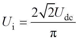
图3的IPT系统电路可简化为图8,Udc为直流电源电压值,S1~S4为高频逆变器的开关器件,电压 为逆变器输出高频电压的基波分量,电感L1、LP与电容C1、CP构成LCC型谐振补偿网络,该电路具有发射线圈电流恒定的特性[25],RP为发射线圈内阻。在副边,Ra、Rb、Rc分别为三组接收绕组内阻。VD1~VD6为整流二极管,CS为补偿电容,电阻RL为系统等效负载。
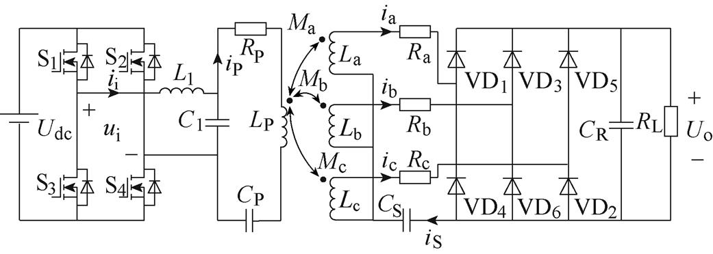
图8 IPT系统简化电路
Fig.8 Simplified circuit diagram of the IPT system
结合图4以及对IPT系统工作模式的分析,系统等效电路可表示为图9,设逆变器工作频率为f,对应角频率为w。

图9 IPT系统等效电路
Fig.9 Equivalent circuit structure of the IPT system
高频逆变器输出基波电压 有效值为
有效值为
 (8)
(8)
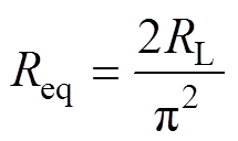
图9中,ii为逆变器输出电流,Z2为副边在原边的反射阻抗,忽略整流桥损耗,由于整流桥工作在半桥整流状态,可得整流桥输入阻抗Req为
 (9)
(9)
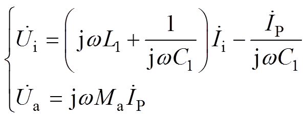
根据基尔霍夫电压定理列写电路方程为
 (10)
(10)
式中, 为i1的相量形式。
当电路各环路谐振时,各电容、电感参数满足
 (11)
(11)
可解得发射线圈电流 为
为
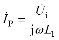 (12)
(12)
三组接收绕组与发射线圈互感满足Ma=Mb=Mc,由式(10)、式(12)可得接收绕组感应电压为
 (13)
(13)
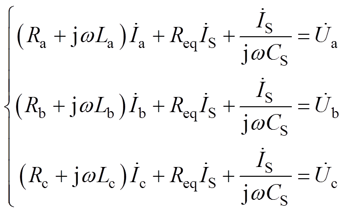
由于各接收绕组参数相同,满足La=Lb=Lc,Ra= Rb=Rc,不难得出各相电流满足 ,在副边根据基尔霍夫电压定理列写电路方程为
 (14)
(14)
 (15)
(15)
进一步可解得整流器输入电压 为
为
 (16)
(16)
其中,电流 为
为
 (17)
(17)
IPT系统输出电压Uo为
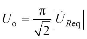 (18)
(18)
由式(16)~式(18)可知,对于不同的负载电阻RL,接收绕组电流 也会随之变化,进而改变系统输出电压Uo,为实现输出电压Uo与负载电阻RL的解耦,保障不同负载下系统输出电压的平稳性,设计电容CS参数满足
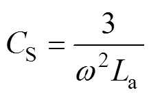 (19)
(19)
此时电容CS同时补偿三组接收绕组消耗的无功功率,电压Uo可通过式(20)求取。可见,由于电阻Ra相对较小,输出电压Uo在负载RL宽范围变化时均可近似保持恒定。
 (20)
(20)
当列车沿轨道行进依次经过各组发射线圈时,由于三组接收绕组长度小于单组发射线圈长度,使得接收绕组分别存在单组发射线圈供电与双组发射线圈供电两种供电模式,各组能量发射线圈传输有功功率随列车位移发生变化。设A、B、C三组接收绕组电流在第j组发射线圈上产生的感应电压分别为 、
、 、
、 ,有
,有
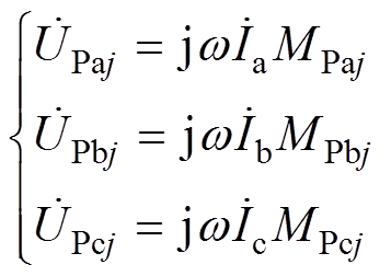 (21)
(21)
式中,j为正整数;MPaj、MPbj、MPcj依次为A、B、C三组接收绕组与第j组发射线圈间的互感。各组发射线圈传输有功功率PTj为
 (22)
(22)
式中, 表示取
表示取 的共轭。
的共轭。
联立式(12)、式(17)与式(21),式(22)可表示为
 (23)
(23)
由上述分析可知,系统第j组能量发射线圈传输的有功功率正比于互感MPaj、MPbj、MPcj的和。利用Ansys/Maxwell有限元软件仿真获得互感MPaj、MPbj、MPcj,进而计算得到有功功率PTj与列车位移量x的关系如图10所示。各组发射线圈传输的有功功率依据互感MPaj、MPbj、MPcj的不同实现自动分配,且由第2节分析可知,在任意位置处各组接收绕组与整体发射线圈互感始终保持恒定,因此IPT系统在列车行进过程中能保持平稳输出。

图10 有功功率随位移x变化曲线
Fig.10 Active power with displacement x
搭建全尺寸实验平台存在占用空间大、建设时间长、投资成本高的问题,采用缩比样机对理论进行验证是磁浮列车领域研究的常用手段。为进一步验证所设计IPT系统可行性,按表2所示耦合机构参数搭建了如图11所示的5 1缩比实验平台,平台输出功率1 kW,工作频率为80 kHz,表2中,N1、N2分别为发射/接收线圈匝数。
表2 样机耦合机构参数
Tab.2 Parameters of the prototype coupler
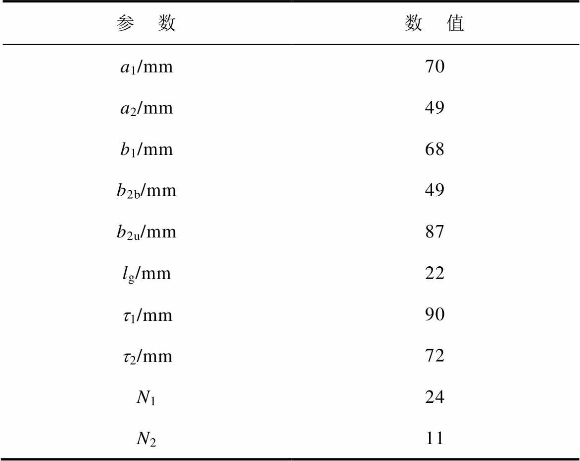
参 数数 值 a1/mm70 a2/mm49 b1/mm68 b2b/mm49 b2u/mm87 lg/mm22 t1/mm90 t2/mm72 N124 N211
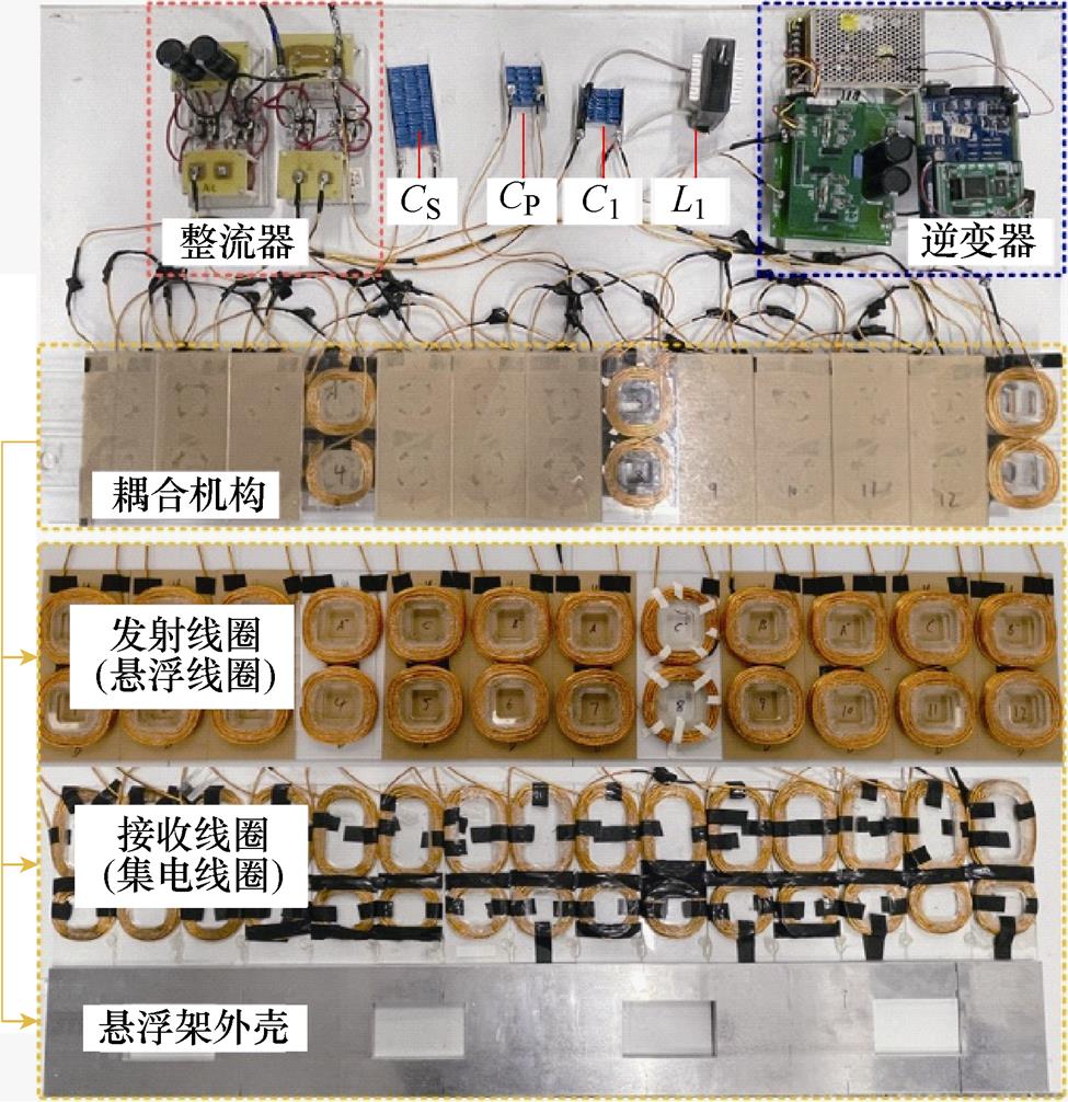
图11 实验装置
Fig.11 Experimental setup
在实验过程中,为模拟真实电动磁浮列车结构,采用与整体集电绕组等长的铝板模拟集电线圈挂靠的悬浮架外壳,各元件参数测量结果见表3。
表3 系统参数设置
Tab.3 Parameters of the system
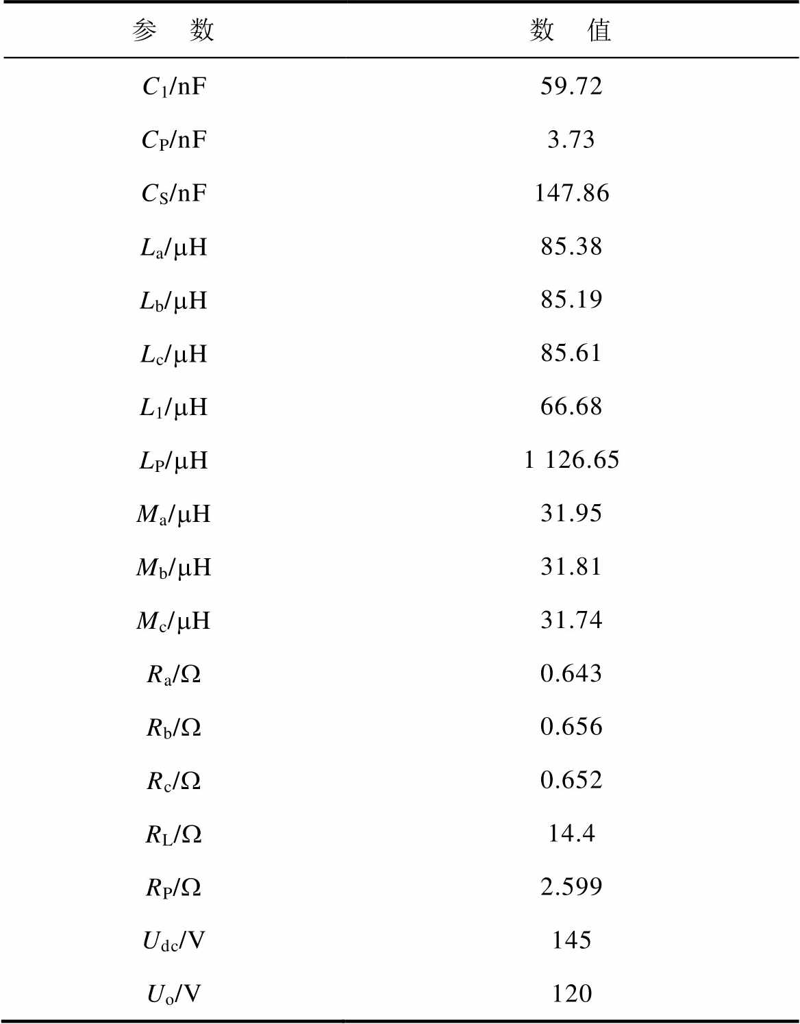
参 数数 值 C1/nF59.72 CP/nF3.73 CS/nF147.86 La/mH85.38 Lb/mH85.19 Lc/mH85.61 L1/mH66.68 LP/mH1 126.65 Ma/mH31.95 Mb/mH31.81 Mc/mH31.74 Ra/W0.643 Rb/W0.656 Rc/W0.652 RL/W14.4 RP/W2.599 Udc/V145 Uo/V120
4.2.1 动态无线供电过程
图12为负载电阻RL为14.4 W 时,集电线圈沿X轴移动,不同位移x下的输出电压Uo与能量传输效率η变化曲线。可见在[-45 mm, 45 mm]移动范围内,系统输出电压波动范围为118.23~121.86 V,系统输出电压波动率仅1.51%,系统能量传输效率始终保持在84.5%附近,复用悬浮线圈与集电线圈作为耦合机构的IPT系统在动态无线供电过程中输出电压波动小,可保持较高的供电平稳性。
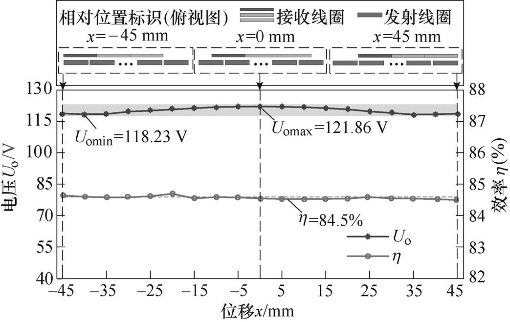
图12 输出电压Uo与效率h 随位移x变化曲线
Fig.12 The output voltage Uo and efficiency hwith displacement x
4.2.2 不同输出功率关键电压/电流波形
图13为系统位移x为-45 mm时,改变电阻RL使系统输出功率变化时逆变器输出电压ui、电流ii,发射线圈电流iP,直流负载电压Uo与接收绕组电流ia、ib、ic波形。可见发射线圈电流iP、直流负载电压Uo在输出功率为1 000、700、500 W时均保持近似恒定。
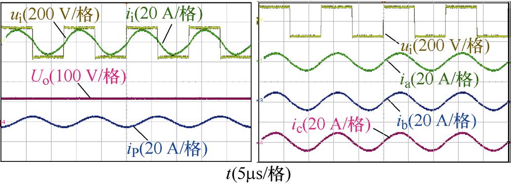
(a)Po=1 000 W
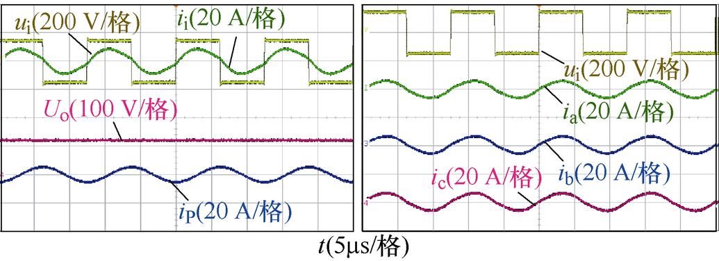
(b)Po=700 W
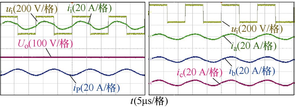
(c)Po=500 W
图13 不同输出功率ui、ii、Uo、ip、ia、ib、ic波形
Fig.13 Waveforms of ui、ii、Uo、ip、ia、ib、ic under different output power
三组不同工况下电流Ia、Ib、Ic的有效值见表4。可见,虽然各组接收绕组参数存在差异,但绕组电流仍可保持相对均衡。
表4 不同输出功率下Ia、Ib、Ic有效值
Tab.4 Effective values of Ia、Ib、Ic under different output power

输出功率/W电流Ia/A电流Ib/A电流Ic/A 1 0006.136.146.26 7004.274.294.37 5003.303.293.34
4.2.3 输出功率-输出电压/能量传输效率
图14为系统位移x为-45 mm时,调整负载电阻RL使输出功率在300~1 000 W变化时直流负载电压Uo、系统能量传输效率h 曲线。
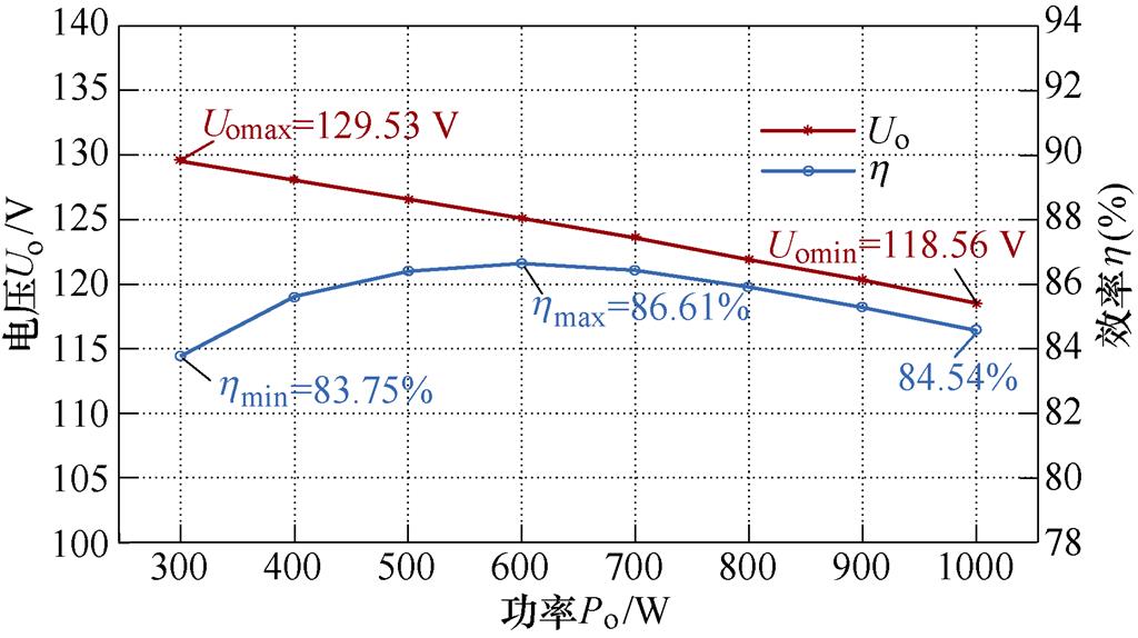
图14 不同输出功率下输出电压Uo与效率h
Fig.14 The output voltage Uo and efficiency hunder different output power
可见系统输出功率逐渐增大时,输出电压从129.53 V减小到118.56 V,波动率为4.42%,能量传输效率从83.75%增大到86.61%,再降低到84.54%,输出功率为600 W时能量传输效率最大。
本文针对IPT技术应用于电动磁浮列车所存在的能量传输机构体积大、重量大的问题,提出了一种利用磁浮系统原有线圈作为能量传输线圈的电动磁浮列车轻量化IPT系统,获得以下结论:
1)通过控制开关的开断,所提出的IPT系统可复用悬浮线圈与集电线圈作为耦合机构在列车低速运行时进行无线电能传输,在车辆侧仅需额外安装补偿电容与开关,满足了IPT系统轻量化需求。同时不影响列车高速运行时原有功能。
2)IPT系统的耦合机构具有移动过程中互感近似恒定的特性,结合基于LCC-S谐振补偿网络的系统电路,可实现移动过程与负载变化过程中的稳压输出。
3)搭建了一套输出功率1 kW的原理样机验证所提方法的可行性,模拟列车移动过程中,输出电压波动仅1.51%,当输出功率在300~1 000 W范围变化时,输出电压波动为4.42%,系统直流到直流效率为83.75%~86.61%。
本文采用缩比实验样机对IPT系统工作原理及平稳输出特性进行了验证,由于缩比降低了线圈品质因数,因此实验结果中能量传输效率较低。实际工程应用的IPT系统采用的线圈品质因数高,能量传输效率可获得进一步提升,后续将开展工程样机的研究与制造工作。
参考文献
[1] 王志涛, 蔡尧, 龚天勇, 等. 基于场-路-运动耦合模型的超导电动悬浮列车特性研究[J]. 中国电机工程学报, 2019, 39(4): 1162-1170.
Wang Zhitao, Cai Yao, Gong Tianyong, et al. Study on characteristics of superconducting electric suspension train based on field-road-motion coupling model[J]. Proceedings of the CSEE, 2019, 39(4): 1162-1170.
[2] 胡道宇, 冯馨月, 张志华. 超导电动悬浮系统阻尼特性研究[J]. 中国电机工程学报, 2021, 41(13): 4679-4687, 28.
Hu Daoyu, Feng Xinyue, Zhang Zhihua. Study on the damping characteristics of superconducting electrody- namic suspension system[J]. Proceedings of the CSEE, 2021, 41(13): 4679-4687, 28.
[3] 王一宇, 蔡尧, 宋旭亮, 等. 零磁通式电动悬浮等效模拟系统的特性分析与实验[J]. 电工技术学报, 2021, 36(8): 1628-1635.
Wang Yiyu, Cai Yao, Song Xuliang, et al. Characteri- stic analysis and experiment of the equivalent simulation system for null-flux electrodynamic suspension[J]. Transactions of China Electrotechnical Society, 2021, 36(8): 1628-1635.
[4] Hasegawa H, Matsue H. Development of a linear generator integrated into an existing superconducting magnet of a yamanashi maglev vehicle[J]. Quarterly Report of RTRI, 2004, 45(1): 21-25.
[5] Hasegawa H, Murai T, Sasakawa T. Electromagnetic analysis of a superconducting magnet for a combined- type linear generator[J]. IEEJ Transactions on Industry Applications, 2001, 121(7): 799-804.
[6] 吕刚, 郭曦临. 电动磁浮列车用直线谐波发电机发电特性计算[J/OL]. 西南交通大学学报, 2022. http://kns.cnki.net/kcms/detail/51.1277.U.20220511.0945.004.html.
Lü Gang, Guo Xilin. Calculation of power generation characteristics of linear harmonic generatorfor elec- trodynamic suspension maglev train[J/OL]. Journal of Southwest Jiaotong University, 2022. http://kns.cnki. net/kcms/detail/51.1277.U.20220511.0945.004.html.
[7] Murai T, Hasegawa H, Fujiwara S. Improvement of inductive power collection in null-flux EDS maglev[J]. IEEJ Transactions on Industry Appli- cations, 1997, 117(1): 81-90.
[8] 吕刚, 郭曦临, 楚志恒, 等. 多工况下电动悬浮系统直线发电机电磁特性研究[J]. 电工技术学报, 2022, 37(22): 5670-5676.
Lü Gang, Guo Xilin, Chu Zhiheng, et al. Elec- tromagnetic characteristics research of electro- dynamics suspension linear generator under multi- condition[J]. Transactions of China Electrotechnical Society, 2022, 37(22): 5670-5676.
[9] 欧阳虹, 蒋兴良, 涂振华, 等. 磁浮接触轨电脉冲除冰的试验研究[J]. 高电压技术, 2022, 48(4): 1553-1560.
Ouyang Hong, Jiang Xingliang, Tu Zhenhua, et al. Experimental study on electro-impulse de-icing of maglev contact rail[J]. High Voltage Engineering, 2022, 48(4): 1553-1560.
[10] 王懿杰, 陆凯兴, 姚友素, 等. 具有强抗偏移性能的电动汽车用无线电能传输系统[J]. 中国电机工程学报, 2019, 39(13): 3907-3916.
Wang Yijie, Lu Kaixing, Yao Yousu, et al. An electric vehicle (EV)-oriented wireless power transfer system featuring high misalignment tolerance[J]. Proceedings of the CSEE, 2019, 39(13): 3907-3916.
[11] 苏玉刚, 刘家鸣, 王智慧, 等. 磁耦合机构拾取线圈平面金属的影响及其抑制方法[J]. 电工技术学报, 2022, 37(3): 578-588.
Su Yugang, Liu Jiaming, Wang Zhihui, et al. Influence analysis of metal in the same plane with pickup coil on magnetic coupler and suppression method[J]. Transactions of China Electrotechnical Society, 2022, 37(3): 578-588.
[12] 宋凯, 朱春波, 李阳, 等. 用于电动汽车动态供电的多初级绕组并联无线电能传输技术[J]. 中国电机工程学报, 2015, 35(17): 4445-4453.
Song Kai, Zhu Chunbo, Li Yang, et al. Wireless power transfer technology for electric vehicle dynamic charging using multi-parallel primary coils[J]. Proceedings of the CSEE, 2015, 35(17): 4445-4453.
[13] 谢文燕, 陈为. 基于组合补偿网络的抗偏移恒流输出无线电能传输系统研究[J]. 电工技术学报, 2022, 37(6): 1495-1512.
Xie Wenyan, Chen Wei. Research on anti-offset constant-current output wireless power transfer system based on combined compensation network[J]. Transactions of China Electrotechnical Society, 2022, 37(6): 1495-1512.
[14] Diekmann A, Hahn W, Kunze K, et al. The support magnet cladding with integrated IPS@ pick-up coil of transrapid vehicles[C]//Maglev: Intemational Con- ference on Magnetically Levitated Systems and Linear Drives, Munich, Germany, 2006: 1-5.
[15] 吴冬华, 冯程程, 余进. 磁浮列车非接触式供电技术[J]. 西南交通大学学报, 2022, 57(3): 522-530.
Wu Donghua, Feng Chengcheng, Yu Jin. Contactless power supply technology for maglev trains[J]. Journal of Southwest Jiaotong University, 2022, 57(3): 522- 530.
[16] Deng Junjun, Zhang Yuanqing, Wang Shuo, et al. The design and coupler optimization of a single- transmitter coupled multireceiver inductive power transfer system for maglev trains[J]. IEEE Transa- ctions on Transportation Electrification, 2021, 7(4): 3173-3184.
[17] Fujie J. An advanced arrangement of the combined propulsion, levitation and guidance system of superconducting maglev[J]. IEEE Transactions on Magnetics, 1999, 35(5): 4049-4051.
[18] 张志华, 张艳清, 闫少强, 等. 适用于磁浮列车全速域运行的非接触供电装置: CN212708981U[P]. 2021-03-16.
[19] Liu Han, Huang Xueliang, Tan Linlin, et al. Dynamic wireless charging for inspection robots based on decentralized energy pickup structure[J]. IEEE Transactions on Industrial Informatics, 2018, 14(4): 1786-1797.
[20] Zaheer A, Hao Hao, Covic G A, et al. Investigation of multiple decoupled coil primary pad topologies in lumped IPT systems for interoperable electric vehicle charging[J]. IEEE Transactions on Power Electronics, 2015, 30(4): 1937-1955.
[21] Chen Yang, Mai Ruikun, Zhang Youyuan, et al. Improving misalignment tolerance for IPT system using a third-coil[J]. IEEE Transactions on Power Electronics, 2019, 34(4): 3009-3013.
[22] Li Hongchao, Liu Yeran, Zhou Kunzhuo, et al. Uniform power IPT system with three-phase trans- mitter and bipolar receiver for dynamic charging[J]. IEEE Transactions on Power Electronics, 2019, 34(3): 2013-2017.
[23] Yamamoto T, Murai T, Hasegawa H, et al. Deve- lopment of distributed-type linear generator with damping control[J]. Quarterly Report of RTRI, 2000, 41(2): 83-88.
[24] 陈凯楠, 蒋烨, 檀添, 等. 轨道交通350kW大功率无线电能传输系统研究[J]. 电工技术学报, 2022, 37(10): 2411-2421, 2445.
Chen Kainan, Jiang Ye, Tan Tian, et al. Research on 350kW high power wireless power transfer system for rail transit[J]. Transactions of China Electrotechnical Society, 2022, 37(10): 2411-2421, 2445.
[25] 夏晨阳, 李晓丽, 韩潇左, 等. IPT系统线性自抗扰恒压输出和最大效率跟踪复合控制方法[J]. 中国电机工程学报, 2022, 42(16): 6042-6052.
Xia Chenyang, Li Xiaoli, Han Xiaozuo, et al. A hybrid control method for achieving constant voltage output with LADRC and maximum efficiency tracking for IPT systems[J]. Proceedings of the CSEE, 2022, 42(16): 6042-6052.
Research on Inductive Power Transfer Method for Electrodynamic Suspension Maglev Train Based on Collector Coil Reuse
Abstract The power supply capacity of the linear generator is insufficient when the electrodynamic suspension (EDS) maglev train is at low speed or stationary. The contact power supply device is used as an additional power supply, resulting in wear, noise, and poor weather resistance, which affect running safety and ride comfort. In recent years, the development of inductive power transfer (IPT) technology has been relatively mature. It uses high-frequency magnetic fields as the medium to realize energy transmission between coupling coils, which has outstanding advantages such as contactless and flexible charging. However, to promote this technology in the maglev train, the IPT system has to be lighter and more compact. Therefore, this paper puts forward a reuse method of coil and circuit to build the integrated IPT system. By changing the coil and circuit structure, the suspension and collector coils, vacant when the train is at low speed, are used as the energy transmission channel. The proposed IPT system has little influence on the dead weight of the maglev train, and the mutual inductance of the coupler can be constant during the moving process. Combined with the LCC-S resonant compensation circuit, the stable output voltage is realized in the train movement and load change process.
First, according to the characteristics of the multi-coil coupling of the electrodynamic suspension maglev train and different coil modes under different speeds, an integrated IPT system based on reconfigurable coils and circuits is proposed. The working modes of coils and circuits at different train speeds are analyzed in detail, and the structure and reconstruction strategy of coils and circuits are designed for contactless power transfer without affecting the original function of the train or increasing the weight of the train.
Then, an equivalent circuit model of the coupler is established to clarify the mutual inductance fluctuation of the coupler during the moving process of the train. The Fourier series is used to characterize the relationship between the mutual inductance of the coils and the displacement, which simplifies the mutual inductance fluctuation analysis of the multi-input multi-output coupler. The results show that the multi-input and multi-output coupler constructed by reusing suspension coils and collector coils has the characteristics of constant mutual inductance during the moving process of the train.
Moreover, to ensure the stable voltage output of the IPT system under different loads, an LCC-S resonant compensation circuit with a centralized compensation capacitor on the secondary side is proposed. Based on the mathematical model of the circuit topology, the compensation topology parameters for realizing the constant voltage output of the system are derived.
Finally, based on the system coil structure and circuit topology, combined with the established mathematical model, a scaled experimental platform for the integrated IPT system of the EDS maglev train is designed and built. Through the experiment, the constant mutual inductance characteristics of the coupler and the constant voltage output characteristics of the system when the load changes are verified. In the moving process, the output voltage fluctuation is only 1.51%. When the output power varies from 300 W to 1 000 W, the output voltage fluctuation is 4.42%, the overall efficiency of the system is at least 83.75%, and the highest is 86.61%.
keywords:Electrodynamic suspension maglev, inductive power transfer, coil reuse, stable output
中图分类号:TM724; U266.4
DOI: 10.19595/j.cnki.1000-6753.tces.222190
河北省自然科学基金面上项目(E2022105047)和中央高校基本科研业务费专项资金项目(2682023ZTPY041)资助。
收稿日期 2022-11-21
改稿日期 2023-06-02
余嘉淇 男,1997年生,硕士研究生,研究方向为感应式电能传输技术。E-mail: swjtu_yujiaqi@163.com
麦瑞坤 男,1980年生,教授,博士生导师,研究方向为无线电能传输在轨道交通中的应用。E-mail: mairk@swjtu.edu.cn(通信作者)
(编辑 郭丽军)