 (1)
(1)
摘要 无取向硅钢铁心的电磁振动是电机噪声的根本来源,采用夹件固定铁心可有效抑制其振动,但夹紧力施加不当会加剧铁心振动,原因为应力使无取向硅钢的磁畴取向发生偏转而引起磁致伸缩形变增大,形成应力各向异性。因此,为了获得准确的应力加载方法,需建立考虑磁畴偏转的无取向硅钢应力各向异性磁致伸缩模型。首先,求解自由能模型并计算能量极值点的分布,模拟无取向硅钢在磁场和应力作用下的磁畴偏转路径;其次,用磁晶各向异性能、应力各向异性能以及磁场能贡献的总和表示无磁滞磁化强度,将自由能模型与考虑磁滞的磁致伸缩模型相结合,通过无取向硅钢磁致伸缩特性测试获取模型参数并进行参数依赖性分析;最后,模拟应力与磁场作用下不同磁化方向的无取向硅钢的磁滞特性和磁致伸缩特性,通过仿真结果与实验结果的对比验证了该模型的准确性。结果表明,应力的增大会使无取向硅钢磁致伸缩应变值减小,同一应力下,磁致伸缩应变的大小会随磁化角度的增大而增大,该文所提出的应力各向异性磁致伸缩模型可以有效模拟此种变化规律。
关键词:应力各向异性 磁畴偏转 自由能模型 磁致伸缩模拟
电工装备电磁振动和噪声的主要来源为硅钢铁心的磁致伸缩效应以及麦克斯韦电磁应力,采用夹紧措施固定铁心可有效抑制电磁应力,但夹紧力过大会导致铁心的导磁能力下降,甚至破坏其正常工作,因此,研究应力对硅钢铁心材料磁特性的影响,对于电工装备的减振降噪至关重要[1-3]。
硅钢材料的自发磁化会形成方向各异的磁畴,磁畴中磁矩的方向为材料的易磁化方向[4-5]。当外加应力和磁场作用于材料时,磁畴的磁矩会产生偏转,导致其易磁化方向发生改变,形成应力各向异性。材料易磁化方向的改变会使电工装备铁心的导磁路径产生偏移,影响其正常的运行状态。因此,在维持设备正常运行的同时,通过施加应力抑制电磁振动需首要解决硅钢应力各向异性的准确模拟问题,其关键为对不同应力和不同磁化方向的磁化和磁致伸缩特性进行磁致伸缩模型构建。
目前,磁致伸缩模型构建方法主要以数据测试、现象学理论、磁畴理论以及热力学关系作为理论基础。基于测量数据的磁致伸缩模型,以特定励磁方式下,特定材料的磁特性测试数据为基础,运用曲面拟合、神经网络、模糊系统等方法模拟材料的磁滞和磁致伸缩特性[6-8]。该方法对正弦磁化下硅钢片的磁致伸缩模拟效果较好,但模型只针对特定励磁方式和特定材料,不具有广泛性,且对数据量及数据准确性依赖较高;基于现象学理论的磁致伸缩模型构建中,分布函数的确定是模型求解的关键,但分布函数需要采用复杂的微积分运算,求解的难度较大[9]。基于磁畴理论的磁致伸缩模型通常从磁畴角度分析磁畴偏转和畴壁移动,进而分析磁特性的变化规律,但磁致伸缩应变量推导困难,且参数计算量巨大[10-11]。基于热力学原理的磁致伸缩模型通过热力学本构关系,获得材料内能的表征多项式,但其多依赖实验规律对模型的化简,缺乏物理基 础[12-13]。因此,对于可用于工程应用的磁致伸缩模型,应计算量适当且模型参数具备物理意义。
为了对应力作用下硅钢不同磁化方向的磁化和磁致伸缩特性进行模拟,张艳丽等依据实验测量的无取向硅钢各向异性磁致伸缩曲线,采用峰峰值对其磁致伸缩各向异性进行模拟,但峰峰值单值曲线无法准确描述磁致伸缩的滞回特性[14]。文献[15]利用神经网络算法对交变磁化下晶粒取向硅钢的磁致伸缩各向异性进行模拟,但所建立的磁致伸缩模型依赖算法的实现,缺乏相应的物理意义。S. S. Mbengue等基于磁畴能量最小原理计算硅钢磁致伸缩应变,但该模型参数获取困难且计算量较大[16]。
综上所述,本文首先基于磁畴理论,求解自由能模型并计算能量极值点,使磁致伸缩模型具备物理基础;其次,用磁晶各向异性能、应力各向异性能以及磁场能贡献的总和表示无磁滞磁化强度,将微观磁畴能量求解与磁致伸缩效应的宏观表征结合,有效地缩减了计算量;最后,仿真与实验曲线基本吻合,说明模型对应力作用下硅钢不同磁化方向的磁化和磁致伸缩特性模拟较为准确,可用于工程应用。
研究硅钢磁畴状态的变化是分析材料宏观磁特性的基础。在无外加应力与磁场情况下,由于材料存在自发磁化,磁畴将随机分布在硅钢任意易磁化方向,此时磁畴能量最低;而外加载荷(如应力和磁场)的作用会使磁畴发生偏转,以寻找新的自由能最低的点,宏观上表现为材料磁特性的变化。为了模拟外加应力与磁场作用下硅钢的磁畴偏转路径,本文建立基于磁畴能量的硅钢自由能模型。
影响硅钢内磁畴偏转的自由能主要包含:磁晶各向异性能Ek、应力各向异性能Es 以及磁场能EH[17],表示为
 (1)
(1)
式中,a1、a2、a3分别为磁化强度M在x、y、z方向的方向余弦;K1和K2为磁晶各向异性常数,K1= 3.8×10⁴ J/m3,K2项忽略不计[18]。
 (2)
(2)
式中,l100、l111分别为硅钢在[1 0 0]、[1 1 1]方向上的磁致伸缩系数,分别取27 mm/m、-5 mm/m[19];b1、b2、b3分别为应力s 在x、y、z方向的方向余弦。
 (3)
(3)
式中,m0为真空磁导率,m0=4p×10-7 H/m;Ms为饱和磁化强度,Ms=1.27×106 A/m;He为材料内有效磁场强度;g1、g2、g3分别为有效磁场强度He在x、y、z方向的方向余弦。
则影响磁畴偏转的自由能E为磁晶各向异性能、应力各向异性能以及磁场能之和,即

 (4)
(4)
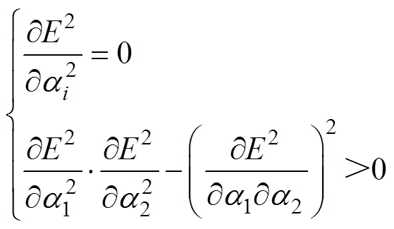
根据磁畴偏转的自由能极小值原理可以明确磁畴的分布状态,因此,外部磁场和应力发生变化时,需要求解新的磁畴能量极小值点,求解条件如下
 (5)
(5)
 (6)
(6)
通过式(5)对自由能方程求偏微分可得到极值点,再通过式(6)对求得的极值点进行判定,可确定其是否为有效极值点。
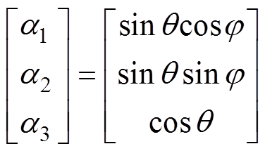
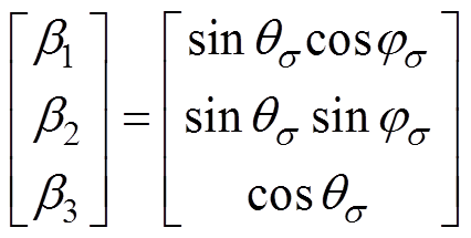
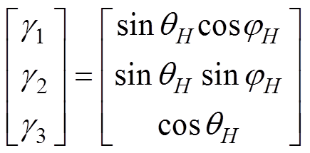
为了便于三维非线性方程式(4)的求解和磁畴偏转路径及特性的分析,可采用坐标等效变换的方法对上述自由能模型进行化简,令磁化方向为[q, j],应力方向为[qs, js ],磁场方向为[qH, jH],建立如图1所示的坐标系,则有
 (7)
(7)
 (8)
(8)
 (9)
(9)
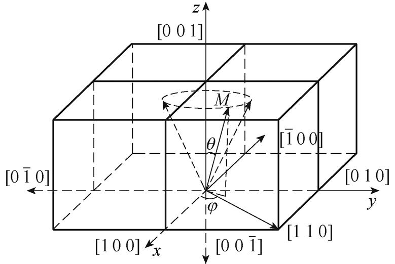
图1 坐标变换示意图
Fig.1 Coordinate transformation diagram
则硅钢的二维自由能模型为
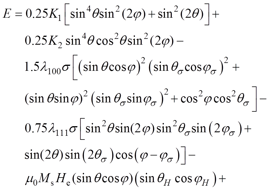
 (10)
(10)
结合二维自由能模型与式(10),可获得不同外加载荷下的磁畴磁化能耗,如图2所示。由于无外加载荷作用时,磁晶各向异性能为磁畴磁化的主要耗能,因此,沿磁化方向耗能越小,磁畴在此方向则更容易磁化。
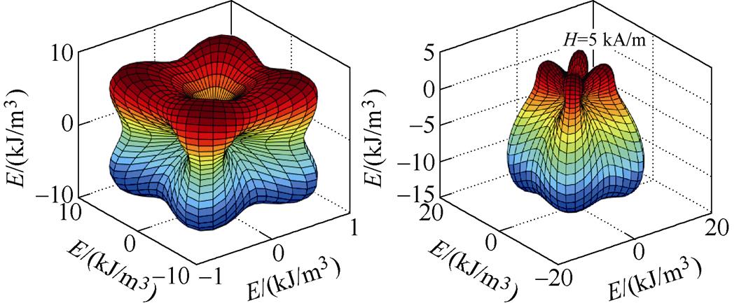
(a)H=0 kA/m, s=0 MPa (b)H=5 kA/m, s=0 MPa
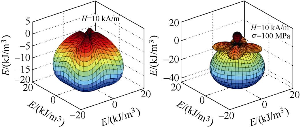
(c)H=10 kA/m, s=0 MPa (d)H=10 kA/m, s=100 MPa
图2 磁畴磁化能耗
Fig.2 Energy consumption diagram for magnetization of magnetic domains
由图2a,对于单个磁畴结构,[1 0 0]方向为易磁化轴,沿此方向磁化概率最大,[1 1 1]方向为难磁化轴,沿此方向耗能最多,磁化概率最小。当沿z轴的外加磁场强度为5 kA/m时,磁化耗能为磁晶各向异性能和磁场能之和,如图2b所示,此时磁场强度的增加使沿z轴正方向磁化耗能变小,而沿z轴负方向耗能增加。当磁场强度增大到10 kA/m时,如图2c所示,这种趋势更加明显,即沿磁化方向外加磁场使磁畴更易磁化。当同时施加磁场和应力时,如图2d所示,磁畴磁化耗能为磁晶各向异性能、磁场能以及应力各向异性能之和,应力使x-y轴平面内的易磁化轴发生旋转,且沿z轴正方向磁化耗能增加,即应力各向异性能为磁畴偏转的主要能量动力,磁晶各向异性能为阻碍磁畴偏离易磁化方向的阻力能量。因此,当外加磁场和应力较小时,磁畴运动以平面内的偏转为主,当应力增大到临界数值时,磁畴将发生平面间角度的跃迁。
在电机铁心中,磁场和应力的方向有以下两种情况如图3所示:①在定子齿上,磁路方向与应力是平行关系,有[qH, jH]=[0°, 0°], [qs, js ]=[0°, 0°]. ②在铁轭上,磁路方向与应力垂直,有[qH, jH]= [0°, 0°], [qs, js ]=[90°, 0°]。通过绘制二维自由能等势曲线来分析磁畴在这两种情况下的偏转路径。

图3 电机铁心中磁场和应力分布示意图
Fig.3 Diagram of magnetic field and stress distribution in motor core
首先,对不考虑外加载荷(s =0, H=0)时的模型进行求解,得到硅钢在未施加应力与磁场作用的易磁化方向,如图4所示,由于材料内的自发磁化作用存在6个易磁化方向,分别为[0 0 1]、[1 0 0]、[0 1 0]、 、
、 、
、 ,此时,硅钢对外表现为无磁性,但随着外磁场和应力载荷的作用,这种稳定的状态将会发生变化,导致磁畴发生偏转,以寻找新的稳定极值点,因此,对外表现为磁特性的改变。
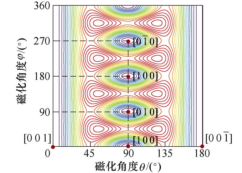
图4 无外加载荷时的自由能二维等势曲线
Fig.4 Two-dimensional contour curves of free energy in the absence of applied loads
其次,对情况①的磁畴偏转进行分析,如图5所示,可知,当沿[0 0 1]方向施加磁场和应力时,磁场的增加有利于磁畴向[0 0 1]方向跃迁,应力的施加则有利于[1 0 0]、[0 1 0]、 、
、 方向磁畴的叠加。由图5a和图5c所示,随着应力增大到10 MPa,应力将会阻碍[1 0 0]、[0 1 0]、
 、
、 方向磁畴向[0 0 1]方向偏转。因此,材料达到磁饱和状态时所需要的磁场大小将随着应力的增大而增大。同时,由图5d可知,磁场增大到12 kA/m时,[1 0 0]、[0 1 0]、
 和
和 方向的能量极值点消失。说明应力的取值应该限定在一定范围内,否则将会阻碍材料内磁畴向磁场方向偏转。
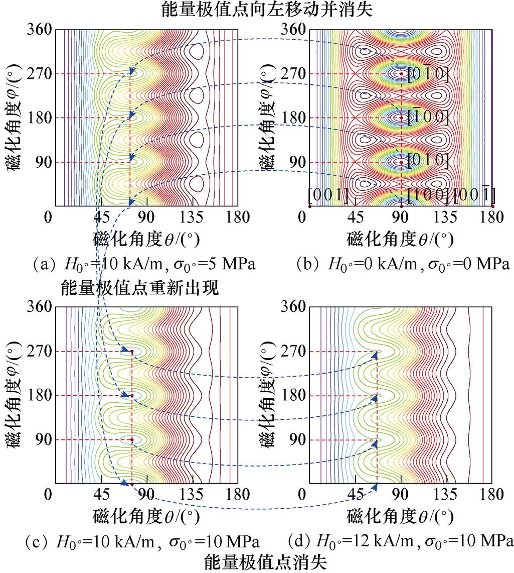
图5 应力与磁场方向平行时的磁畴偏转图
Fig.5 Diagram of domain deflection when stress is parallel to the direction of magnetic field
最后,对情况②的磁畴偏转进行分析,应力与磁场方向垂直时的磁畴偏转如图6所示。由图6可知,当磁场和应力分别沿[0 0 1]和[1 0 0]方向施 加时,磁畴偏转角度整体趋向于[0 0 1]方向;随着应力增加到25 MPa,磁畴逐渐向垂直于应力方向的[0 1 0]和 方向偏移,如图6a所示。随着磁场增大到12 kA/m,[0 1 0]和
 方向的能量极值点消失,磁畴偏转角度恢复到理想状态,如图6c所示。应力的增加会使[1 0 0]方向磁畴更容易向磁场方向偏转,但会使[0 1 0]方向磁畴发生跃迁时的跃迁磁场增大。因此在满足铁心正常工作的情况下,应力要尽可能小。
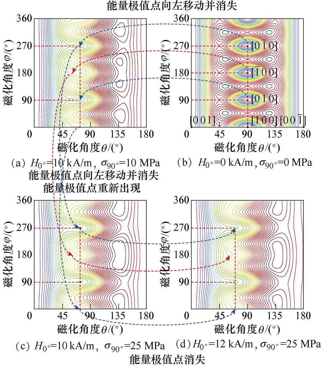
图6 应力与磁场方向垂直时的磁畴偏转
Fig.6 Diagram of domain deflection when stress is perpendicular to the direction of magnetic field
自由能模型的准确性依赖材料参数Ms、K1、K2、l100、l111的取值,为了研究参数对硅钢材料磁畴偏转情况以及磁化过程的影响,改变参数Ms、K1、K2、l100、l111取值,模拟磁畴跃迁磁场的变化情况。
应力方向与磁场方向平行和垂直两种情况下,参数K1与K2的取值对跃迁磁场强度的影响分别如图7、图8所示,可知,应力与磁场平行时,随着K1的增大,跃迁磁场强度曲线逐渐上移;应力与磁场方向垂直时,随着应力的增大,[1 0 0]方向磁畴所需跃迁磁场强度减小,磁畴易发生跃迁。这说明随着K1的增大,磁畴偏转越慢,所需的跃迁磁场强度越大。因此,磁晶各向异性能会阻碍磁畴偏转,当其增大时则需要更大的应力载荷来使磁畴发生跃迁,同时,随着参数K2取值的变化,曲线基本保持不变,说明参数K2的取值不影响硅钢材料的磁畴偏转和磁化过程。
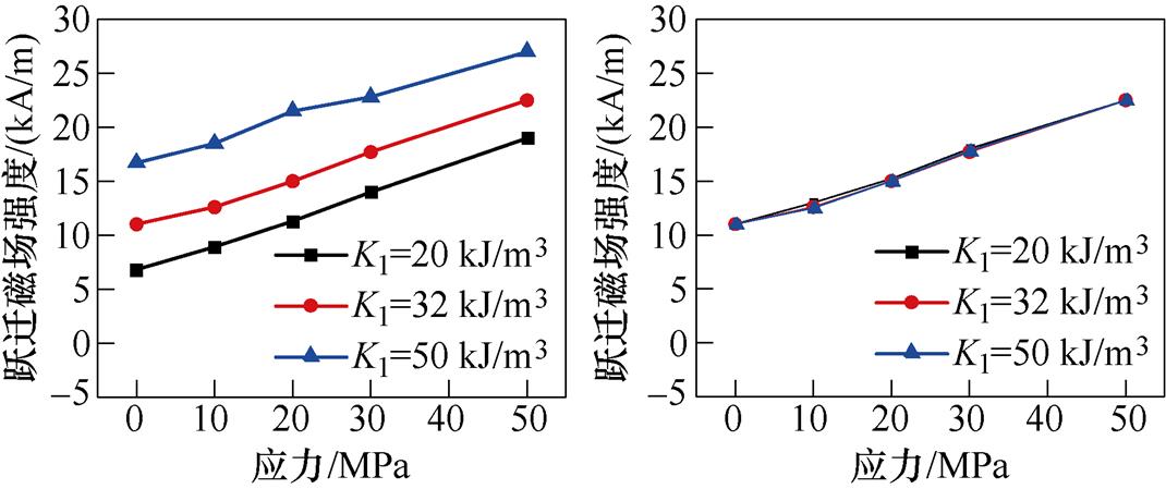
(a)K1不同 (b)K2不同
图7 应力与磁场方向平行时[1 0 0]方向磁畴的跃迁磁场
Fig.7 Jump magnetic field of domain in [1 0 0] direction when stress is parallel to the direction of magnetic field
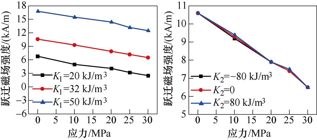
(a)K1不同 (b)K2不同
图8 应力与磁场方向垂直时[1 0 0]方向磁畴的跃迁磁场
Fig.8 Jump magnetic field of domain in [1 0 0] direction when stress is perpendicular to magnetic field
应力方向与磁场平行和垂直两种情况下,参数Ms对跃迁磁场强度的影响如图9所示,可知,在应力与磁场方向平行时,随着应力的增加,[1 0 0]方向磁畴跃迁所需要的跃迁磁场强度越来越大;由图9b可知,在应力与磁场垂直时,随着Ms的增大,磁畴的跃迁磁场强度越小,这是应力各向异性能与磁场能竞争的结果,即应力阻碍[1 0 0]方向磁畴向磁场方向偏转。然而,随着Ms的增大,曲线逐渐下移,这是由于材料的磁场能随Ms取值的增大而增大,因此在应力各向异性能不变的情况下,磁畴跃迁时所需的外加磁场将减小,即跃迁磁场强度减小。
应力与磁场平行时,参数l100、l111对跃迁磁场强度的影响如图10所示,可知,随着l100的增大,在应力相同时,[1 0 0]方向磁畴的跃迁磁场强度越来越大,即l100的增大不利于[1 0 0]方向磁畴向磁场方向偏转;当l100取负值时,磁畴的跃迁磁场强度随应力的增加而减小,即l100为负值应力的增加使[1 0 0]方向磁畴更易发生偏转,l100为正值时阻碍[1 0 0]方向磁畴发生偏转。图10b中,不同l111取值时,跃迁磁场强度曲线基本重合,即l111的变化不影响硅钢材料磁畴的偏转。同理可知,应力方向与磁场垂直时,l100、l111取值会影响使应力各向异性能大小发生变化,从而影响磁畴偏转快慢。
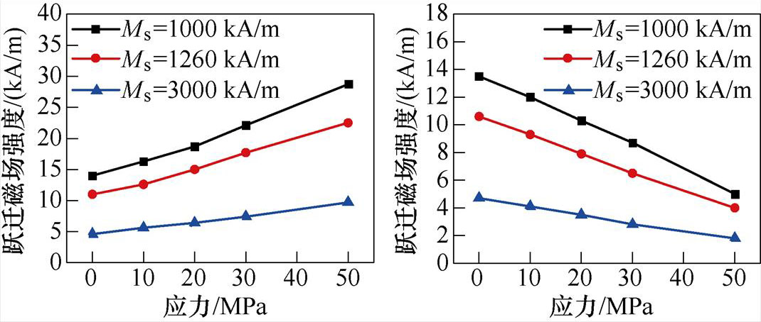
(a)应力与磁场方向平行 (b)应力与磁场方向垂直
图9 不同Ms下[1 0 0]方向磁畴的跃迁磁场
Fig.9 Jump magnetic field of domain in [1 0 0] direction under different Ms
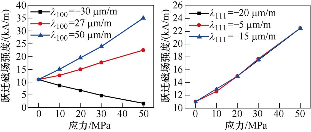
(a)l100不同 (b)l111不同
图10 应力与磁场方向平行时[1 0 0]方向磁畴的跃迁磁场
Fig.10 Jump magnetic field of domain in [1 0 0] direction when stress is parallel to the direction of magnetic field
对于各向同性材料,通常采用Jiles-Atherton模型模拟材料畴壁的钉扎效应,需要利用Langevin函数计算各向同性材料的无磁滞磁化强度Man,描述材料的磁滞特性,并将其与二次畴转模型结合来模拟材料的磁致伸缩特性。然而,对于各向异性材料,由于不同方向的各向异性能量不同,Langevin函数将不再适用。因此,在计算各向异性材料的磁化强度时,需要考虑材料的各向异性能量,建立能够描述材料应力各向异性的磁致伸缩模型。
由1.1节可知,影响硅钢磁畴偏转的自由能E主要包含磁晶各向异性能Ek、应力各向异性能Es 以及磁场能EH。在各向异性材料中,考虑沿磁场方向的磁矩对磁化的贡献,无磁滞磁化强度Man可以通过其贡献的总和来计算,即
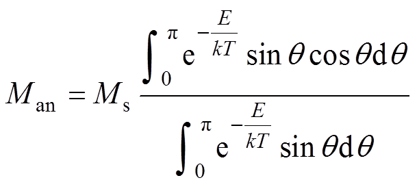 (11)
(11)
式中,q 为磁场方向和磁矩方向之间的夹角;E可以由式(10)进行计算;kT为玻耳兹曼能量。
考虑应力、钉扎效应、退磁系数和Weiss分子场的作用,材料应变l(s, M)与有效磁场强度He(s, M)可表示[20]为
 (12)
(12)
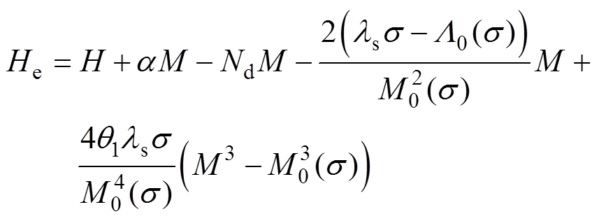 (13)
(13)
式中,ls为无应力时的饱和磁致伸缩应变;l0(s)为由畴壁运动所引起的磁致伸缩应变;M0(s)为畴壁运动导致的饱和壁移磁化强度;a 为考虑Weiss分子场作用时的耦合系数;Nd为退磁系数;Hs 为考虑应力场的有效场计算函数;l0(s)的原函数是Λ0(s);引入阶跃函数q1描述磁畴壁移到磁畴旋转的过程,其自变量为磁化强度M,当M≤M0(s)时,q1=0;当M>M0(s)时,q1为一个常数。
式(13)对磁场强度求微分,得
 (14)
(14)
基于Jiles-Atherton理论,考虑硅钢材料的磁滞特性,则可以用可逆磁化参数c与不可逆分量Mirr来描述其磁化强度M,即
 (15)
(15)
式(15)对磁场强度求微分,得
 (16)
(16)
由能量守恒原理
 (17)
(17)
式中,k为钉扎位点的平均密度;d 为方向系数,其取值为1或-1取决于磁场是增大或减小。
式(17)对有效磁场强度He取微分,有
 (18)
(18)
联立式(14)、式(16)、式(18)可得考虑应力各向异性的硅钢磁滞模型为

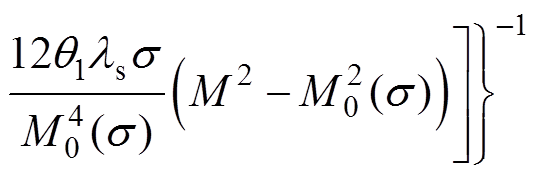 (19)
(19)
式中,dMan/dH由式(10)和式(11)求得。
联立式(12),并与考虑各向异性的硅钢磁滞模型相结合,可得到励磁状态下考虑应力各向异性的硅钢磁致伸缩模型表示为
 (20)
(20)
考虑钉扎效应的影响,为准确描述磁致伸缩曲线的滞回特性,根据实验数据,引入表示磁致伸缩曲线退磁过程中的参数:材料达到饱和壁移磁化强度M0(s)时,及其在退磁状态下对应的磁致伸缩应lws(s)和材料达到饱和磁化强度时对应的磁致伸缩应变lm(s),则退磁状态下考虑应力各向异性的硅钢磁致伸缩模型表示为
 (21)
(21)
为了获得模型参数,需要对不同磁化方向的无取向硅钢磁特性进行测试,搭建硅钢片磁致伸缩测量系统,如图11a所示,测量系统符合IEC标准,测量的硅钢样片50WW470(长600 mm,宽100 mm)按照如图11b所示角度进行切割。首先,通过LabVIEW软件控制系统产生励磁电压,经过功率放大器放大后的励磁电压信号,通过保护电路后加在单片测量仪的初级绕组上,使磁轭和测量样片中形成磁路;然后,样片中交变磁场形成的感应电压信号通过电压探头测量次级绕组电压获得,初级绕组电流使用电流探头测量,二者通过前置放大器与LabVIEW数据采集卡相连;之后,单片测量仪中的应变信号经由应变桥盒和应变放大器汇集到数据采集卡中;最后,由LabVIEW软件控制系统实现给定条件下硅钢样片的磁特性测量与控制。
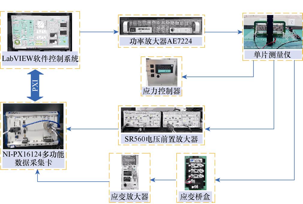
(a)磁致伸缩测量实物
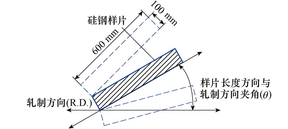
(b)剪切方向与轧制方向成q 角(q =0°, 15°, 30°,…, 90°)
图11 磁致伸缩测量
Fig.11 Magnetostrictive measurement
将不同磁化方向的磁致伸缩曲线用极坐标表示,如图12所示,可知,无取向硅钢磁致伸缩存在明显的各向异性,同一应力下,磁致伸缩应变的大小随着磁化角度的增大而增大;在同一磁化方向,应力的增加会使磁致伸缩应变减小,即无取向硅钢磁致伸缩应变的大小与应力的大小和磁场与轧制方向所成角度有关。
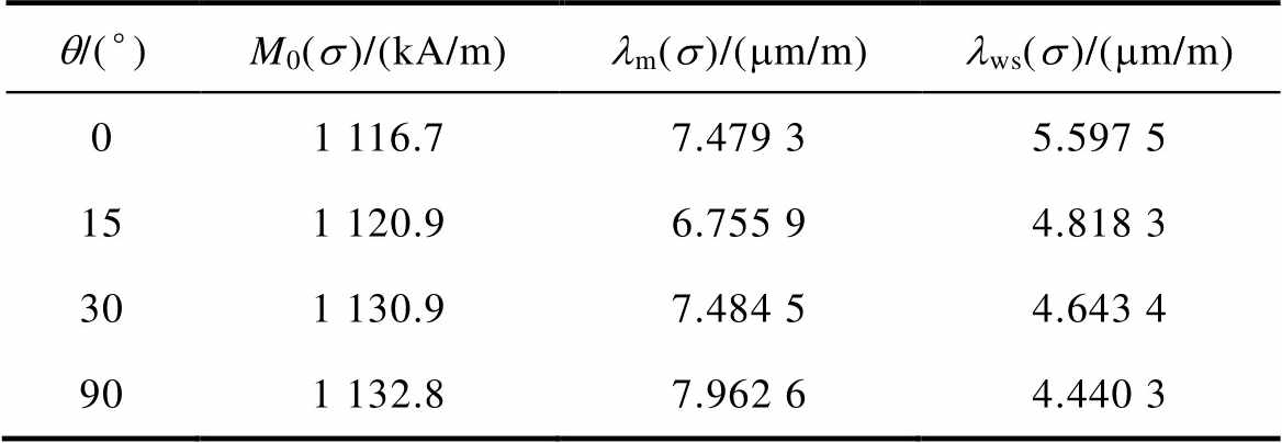
根据实验测量结果提取模型参数M0(s)、lm(s)和lws(s)。其中,M0(s)为磁滞回线中饱和壁移磁化强度,lm(s)为饱和磁化强度对应的磁致伸缩应变,lws(s)为退磁状态下的饱和壁移磁化强度对应的磁致伸缩应变,对应的参数提取点如图13所示。
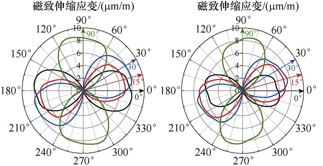
(a)s =0 MPa (b)s =1.2 MPa
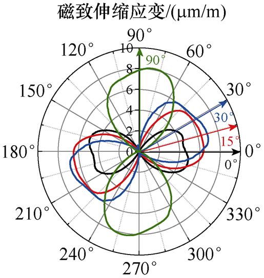
(c)s =2 MPa
图12 极坐标下不同磁化方向的磁致伸缩曲线
Fig.12 Magnetostrictive curves along different magnetization directions in polar coordinate
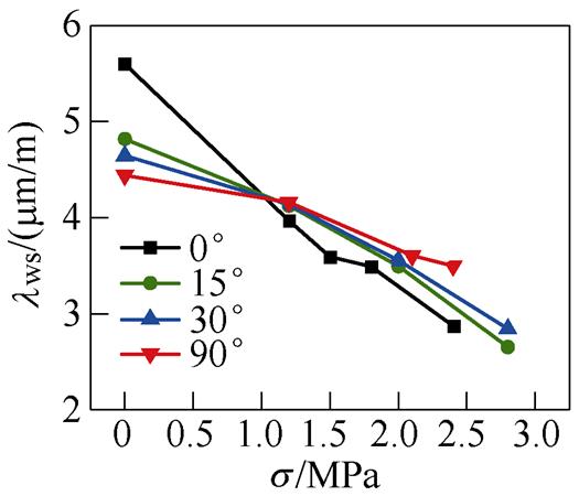
为了验证模型参数提取的必要性,分析模型参数(饱和壁移磁化强度M0、饱和磁致伸缩应变lm和饱和壁移磁化强度lws)对应力和磁化方向的依赖性,如图14所示,从图中可知,当应力和磁化方向改变时,模型的三个参数均会产生较大变化,这说明其对应力和磁化方向具有较大的依赖性,且随着应力的增大三个参数值呈现非线性减小,随着磁化方向的增大而非线性增大。因此,在无取向硅钢应力各向异性磁致伸缩特性模拟中,必须对不同应力和磁化方向的模型参数进行提取。
根据所提取的模型参数,结合本文提出的应力各向异性磁致伸缩模型,对不同磁化方向和应力下的磁滞特性和磁致伸缩特性进行模拟。
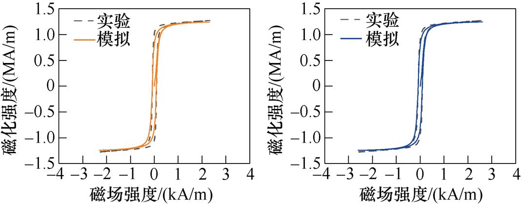
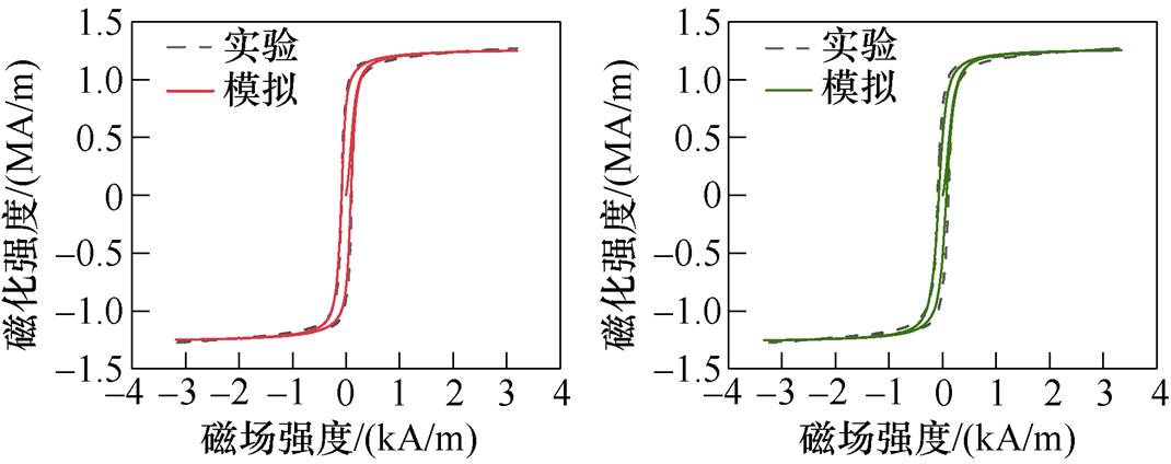
首先,分析无取向硅钢无应力作用下的各向异性磁致伸缩特性。根据表1所示不同磁化方向模型参数,模拟无应力时无取向硅钢不同磁化方向的磁滞回线和磁致伸缩回线,与实验测量值的对比分别如图15和图16所示。从不同磁化方向的磁滞回线可以看出,随着磁化角度的增大,起始磁化曲线的斜率在减小,导磁性能也逐渐降低。对比不同磁化方向的磁致伸缩回线,硅钢在磁化角度较小时,磁致伸缩较小,偏离轧制方向的角度越大,硅钢材料磁致伸缩越明显,垂直轧制方向时磁致伸缩达到最大。
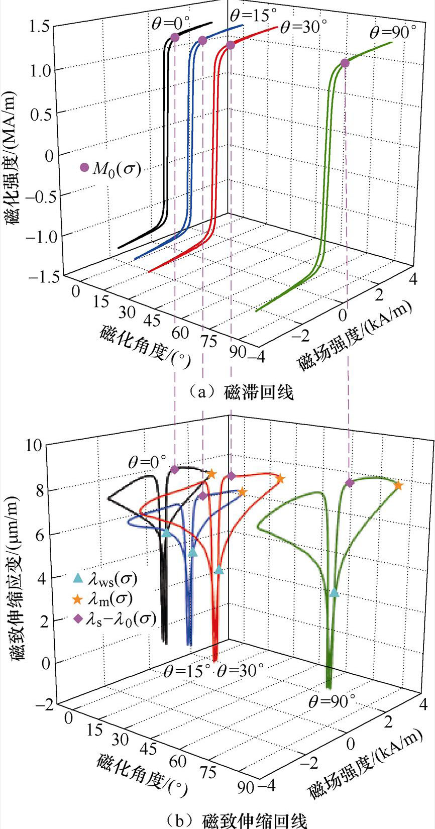
图13 磁特性曲线测量值及参数提取点
Fig.13 Measured magnetic characteristic curves and the parameter extraction point
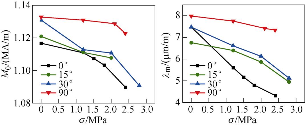
(a)参数M0 (b)参数lm
(c)参数lws
图14 模型参数对应力和磁化方向的依赖性
Fig.14 Dependence of model parameters on stress and magnetization direction
(a)0° (b)15°
(c)30° (d)90°
图15 不同磁化方向上磁滞回线对比
Fig.15 Comparison of hysteresis loops in different magnetization directions
表1 不同磁化方向的磁致伸缩模型参数
Tab.1 Magnetostrictive model parameters of different magnetization directions
q/(°)M0(s)/(kA/m)lm(s)/(mm/m)lws(s)/(mm/m) 01 116.77.479 35.597 5 151 120.96.755 94.818 3 301 130.97.484 54.643 4 901 132.87.962 64.440 3
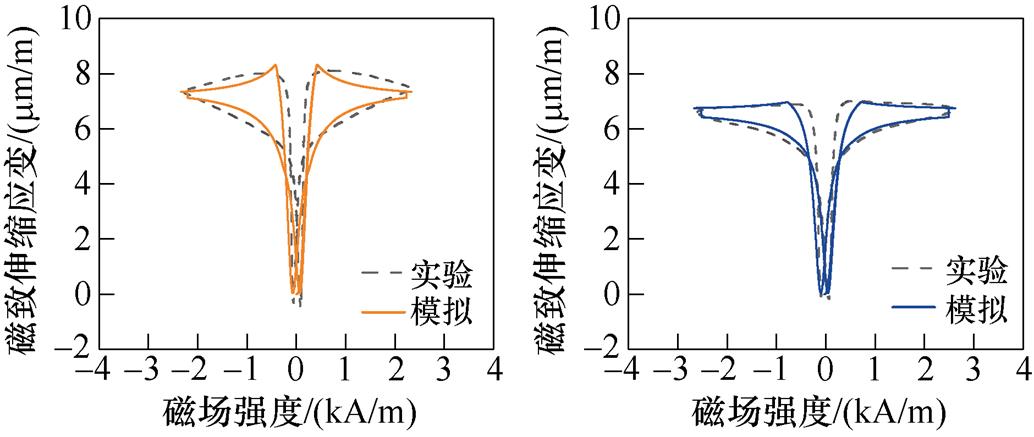
(a)0° (b)15°
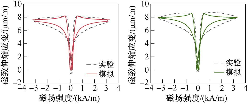
(c)30° (d)90°
图16 不同磁化方向上磁致伸缩回线对比
Fig.16 Comparison of magnetostrictive loops in different magnetization directions
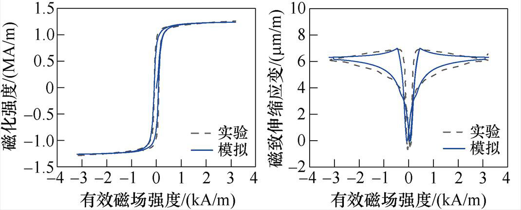
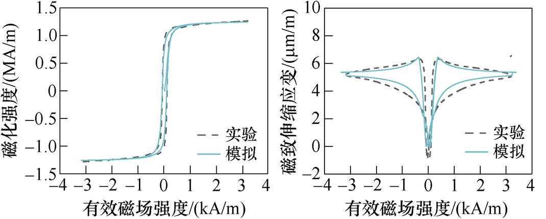
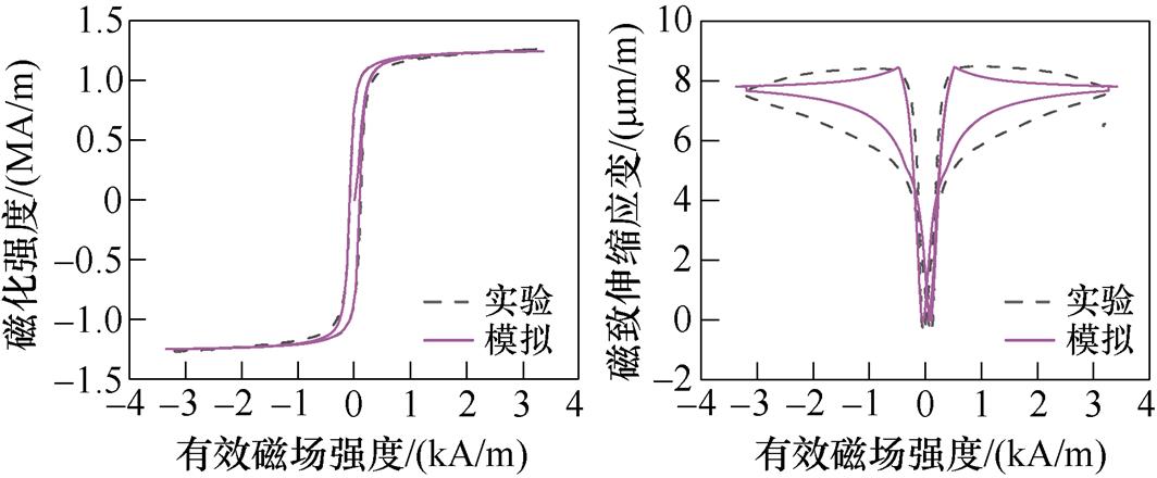
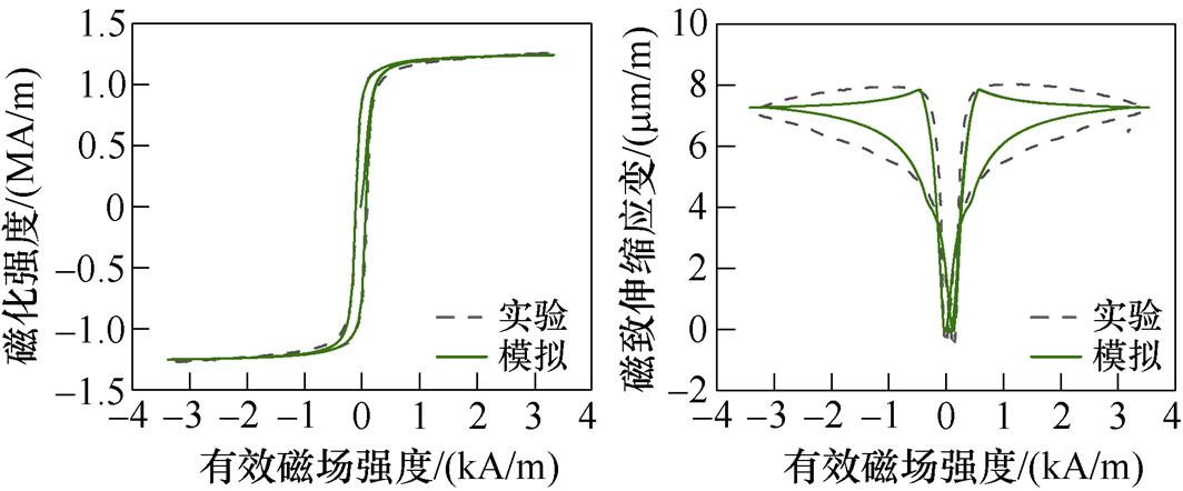
其次,分析应力和磁场作用下无取向硅钢的各向异性磁致伸缩特性。根据表2所示模型参数,模拟不同应力作用下无取向硅钢磁化方向为30°和 90°的磁滞回线和磁致伸缩回线,此处采用应力相关项有效磁场强度He作为图中的横坐标,其与实验测量值的对比分别如图17和图18所示。
表2 应力作用时不同磁化方向的磁致伸缩模型参数
Tab.2 Magnetostrictive model parameters of different magnetization directions under different stresses
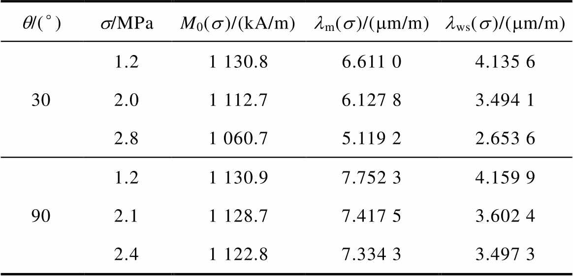
q/(°)s/MPaM0(s)/(kA/m)lm(s)/(mm/m)lws(s)/(mm/m) 301.21 130.86.611 04.135 6 2.01 112.76.127 83.494 1 2.81 060.75.119 22.653 6 901.21 130.97.752 34.159 9 2.11 128.77.417 53.602 4 2.41 122.87.334 33.497 3
由图17和图18,对比同一磁化方向上不同应力下的磁滞回线与磁致伸缩回线可知,应力的增加会使起始磁化曲线的斜率增加,即无取向硅钢更容易磁化,同时,应力各向异性能Es 有助于磁畴向外加磁场方向偏转,使得材料达到磁饱和状态时需要的外加磁场更小,即应力的增加使材料的磁致伸缩应变减小。同时,当磁化方向为30°时,不同应力下的磁滞回线与磁致伸缩回线实验测量结果与仿真结果基本一致;当磁化方向为90°,即磁化方向垂直于轧制方向时,模型仍存在误差,这是由于在磁致伸缩应变的建模中仅考虑磁畴的偏转,而磁畴壁的厚度和畴壁内原子磁矩的变化会影响磁畴结构的形成及磁畴能量的变化,从而对外表现出对磁致伸缩应变的影响。
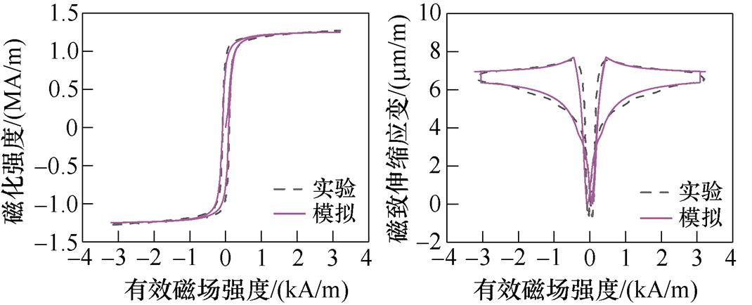
(a)30°,1.2 MPa磁滞回线 (b)30°,1.2 MPa磁致伸缩回线
(c)30°,2 MPa磁滞回线(d)30°,2 MPa磁致伸缩回线
(e)30°,2.8 MPa磁滞回线(f)30°,2.8 MPa磁致伸缩回线
图17 30°时不同应力下的磁滞回线和磁致伸缩回线
Fig.17 Hysteresis loops and magnetostriction loops under different stresses at 30°
(a)90°,1.2 MPa磁滞回线 (b)90°,1.2 MPa磁致伸缩回线
(c)90°,2.1 MPa磁滞回线 (d)90°,2.1 MPa磁致伸缩回线
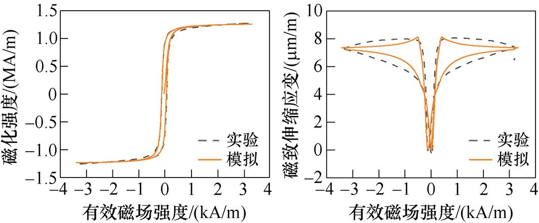
(e)90°,2.4 MPa磁滞回线 (f)90°,2.4 MPa磁致伸缩回线
图18 90°时不同应力下的磁滞回线和磁致伸缩回线
Fig.18 Hysteresis loops and magnetostriction loops under different stresses at 90°
考虑外加磁场和应力作用下磁畴的偏转路径和磁化耗能,本文建立无取向硅钢应力各向异性磁致伸缩模型,并进行实验验证,从磁畴偏转的角度对无取向硅钢磁致伸缩各向异性进行模拟,得出如下结论:磁致伸缩应变的大小随着应力的增大而减小,随着磁化角度的增大而增大;通过对不同磁场和应力作用下磁畴偏转路径的模拟可知,应力的作用会使硅钢中90°磁畴的体积分数增大,引起材料的磁导率降低;在磁场作用下,应力各向异性能会阻碍磁畴的偏转和跃迁,使无取向硅钢磁化更加困难,随着应力的增大,材料达到磁化饱和需要的磁场也会增大。
参考文献
[1] 祝丽花, 李晶晶, 朱建国. 服役条件下取向硅钢磁致伸缩模型的研究[J]. 电工技术学报, 2020, 35(19): 4131-4138.
Zhu Lihua, Li Jingjing, Zhu Jianguo. Research on magnetostrictive model for oriented silicon steel under service conditions[J]. Transactions of China Electrotechnical Society, 2020, 35(19): 4131-4138.
[2] Belahcen A. Vibrations of rotating electrical machines due to magnetomechanical coupling and magnetostriction[J]. IEEE Transactions on Magnetics, 2006, 42(4): 971-974.
[3] 陈龙, 易琼洋, 贲彤, 等. 全局优化算法在Preisach磁滞模型参数辨识问题中的应用与性能对比[J]. 电工技术学报, 2021, 36(12): 2585-2593, 2606.
Chen Long, Yi Qiongyang, Ben Tong, et al. Appli- cation and performance comparison of global optimization algorithms in the parameter identi- fication problems of the Preisach hysteresis model[J]. Transactions of China Electrotechnical Society, 2021, 36(12): 2585-2593, 2606.
[4] Gao Yanhui, Fujiki T, Dozono H, et al. Modeling of magnetic characteristics of soft magnetic composite using magnetic field analysis[J]. IEEE Transactions on Magnetics, 2018, 54(3): 1-4.
[5] 贲彤, 陈龙, 闫荣格, 等. 考虑磁化及磁致伸缩特性各向异性的感应电机铁心电磁应力分析[J]. 电工技术学报, 2019, 34(1): 66-74.
Ben Tong, Chen Long, Yan Rongge, et al. Stress analysis of induction motor core considering aniso- tropic magnetic and magnetostrictive properties[J]. Transactions of China Electrotechnical Society, 2019, 34(1): 66-74.
[6] 刘任, 李琳, 王亚琦, 等. 基于随机性与确定性混合优化算法的Jiles-Atherton磁滞模型参数提取[J]. 电工技术学报, 2019, 34(11): 2260-2268.
Liu Ren, Li Lin, Wang Yaqi, et al. Parameter extraction for Jiles-Atherton hysteresis model based on the hybrid technique of stochastic and deter- ministic optimization algorithm[J]. Transactions of China Electrotechnical Society, 2019, 34(11): 2260- 2268.
[7] 王洋, 刘志珍. 基于蛙跳模糊算法的Jiles Atherton铁心磁滞模型参数确定[J]. 电工技术学报, 2017, 32(4): 154-161.
Wang Yang, Liu Zhizhen. Determination of Jiles Atherton core hysteresis model parameters based on fuzzy-shuffled frog leaping algorithm[J]. Transa- ctions of China Electrotechnical Society, 2017, 32(4): 154-161.
[8] 李岱岩, 张艳丽, 荆盈, 等. 基于J-A模型的电工钢片磁致伸缩特性模拟与实验[J]. 电工技术学报, 2022, 37(20): 5081-5091.
Li Daiyan, Zhang Yanli, Jing Ying, et al. Modeling of magnetostrictive characteristics in an electrical steel sheet based on the J-A model and its experimental verification[J]. Transactions of China Electrotech- nical Society, 2022, 37(20): 5081-5091.
[9] Jin Ke, Kou Yong, Zheng Xiaojing. A nonlinear magneto-thermo-elastic coupled hysteretic consti- tutive model for magnetostrictive alloys[J]. Journal of Magnetism and Magnetic Materials, 2012, 324(12): 1954-1961.
[10] Jiles D C, Thoelke J B. Theoretical modelling of the effects of anisotropy and stress on the magnetization and magnetostriction of Tb0.3Dy0.7Fe2[J]. Journal of Magnetism and Magnetic Materials, 1994, 134(1): 143-160.
[11] 李梦星, 张艳丽, 姜伟, 等. 机械应力下电工钢片磁滞与磁致伸缩回环滞后特性模拟[J]. 电工技术学报, 2022, 37(11): 2698-2706.
Li Mengxing, Zhang Yanli, Jiang Wei, et al. Simu- lation of hysteresis and magnetostrictive loop hysteretic characteristics of electrical steel sheets under mechanical stress[J]. Transactions of China Electrotechnical Society, 2022, 37(11): 2698-2706.
[12] 张鹏宁, 李琳, 聂京凯, 等. 考虑铁心磁致伸缩与绕组受力的高压并联电抗器振动研究[J]. 电工技术学报, 2018, 33(13): 3130-3139.
Zhang Pengning, Li Lin, Nie Jingkai, et al. Study on the vibration of high voltage shunt reactor considering of magnetostriction and winding force[J]. Transa- ctions of China Electrotechnical Society, 2018, 33(13): 3130-3139.
[13] 张黎, 王国政, 董攀婷, 等. 基于磁致伸缩本征特性的晶粒取向性变压器铁心振动模型[J]. 中国电机工程学报, 2016, 36(14): 3990-4001.
Zhang Li, Wang Guozheng, Dong Panting, et al. Study on the vibration of grain-oriented transformer core based on the magnetostrictive intrinsic charac- teristics[J]. Proceedings of the CSEE, 2016, 36(14): 3990-4001.
[14] 张艳丽, 孙小光, 谢德馨, 等. 无取向硅钢片各向异性磁致伸缩特性模拟[J]. 中国电机工程学报, 2014, 34(27): 4731-4736.
Zhang Yanli, Sun Xiaoguang, Xie Dexin, et al. Modeling of anisotropic magnetostriction property of non-oriented silicon steel sheet[J]. Proceedings of the CSEE, 2014, 34(27): 4731-4736.
[15] Wang Zhen, Zhang Yanli, Ren Ziyan, et al. Modeling of anisotropic magnetostriction under DC bias based on an optimized BP neural network[J]. IEEE Transa- ctions on Magnetics, 2020, 56(3): 1-4.
[16] Mbengue S S, Buiron N, Lanfranchi V. Macroscopic modeling of anisotropic magnetostriction and mag- netization in soft ferromagnetic materials[J]. Journal of Magnetism and Magnetic Materials, 2016, 404: 74-78.
[17] Vanoost D. Magnetic hysteresis at the domain scale of a multi-scale material model for magneto-elastic behaviour[J]. Journal of Magnetism and Magnetic Materials, 2016, 414: 168-179.
[18] 戴道生. 物质磁性基础[M]. 北京: 北京大学出版社, 2016.
[19] Moses A J, Anderson P I, Somkun S. Modeling 2-D magnetostriction in nonoriented electrical steels using a simple magnetic domain model[J]. IEEE Transa- ctions on Magnetics, 2015, 51(5): 1-7.
[20] 贲彤, 陈芳媛, 陈龙, 等. 考虑力-磁耦合效应的无取向电工钢片磁致伸缩模型的改进[J]. 中国电机工程学报, 2021, 41(15): 5361-5371.
Ben Tong, Chen Fangyuan, Chen Long, et al. An improved magnetostrictive model of non-oriented electrical steel sheet considering force-magnetic coupling effect[J]. Proceedings of the CSEE, 2021, 41(15): 5361-5371.
Simulation of Stress-Induced Anisotropic Magnetostrictive Properties of Non-Oriented Silicon Steel Considering Magnetic Domain Deflection
Abstract Vibration and noise become important factors that restrict the development of motors to large capacity. The most effective method is to fix the cores with clamps and shells. However, the stress from clamps and shells will deflect the magnetic domain of the core silicon steel material, resulting in stress anisotropy, which affects the degree of magnetization and magnetostriction of the material. Thus, considering the deflection of magnetic domains, a stress-induced anisotropic magnetostrictive model is proposed to simulate the mag- netostrictive properties of non-oriented silicon steel with different stress and magnetization directions.Comparing the simulation results with the experimental results shows that the proposed model is effective.
Firstly, the free energy model of silicon steel is established to obtain the magnetic domain deflection path under different applied stress and magnetic fields. The free energy model is simplified by coordinate transformation, and the distribution of energy extremum is calculated. The magnetic domain magnetization energy consumption diagram and magnetic domain deflection path of non-oriented silicon steel under the external magnetic field and stress are also simulated. The influence of free energy model parameters (Ms, K1, K2, l100, l111) on the model and the magnetic domain deflection is analyzed. Then, the hysteretic magnetization is expressed by the sum of the magnetic crystal anisotropy energy, stress-inducedanisotropic energy, and magnetic field energy contribution. Combined the free energy model with the magnetostriction model considering hysteresis, the stress-induced anisotropic magnetostriction model of non-oriented silicon steel is established by improving the hysteretic magnetization. The model parameters are obtained through the hysteresis and magnetostrictive propertytest of non-oriented silicon steel, and the parameter dependence analysis is carried out. Finally, the hysteresis and magnetostrictive properties of non-oriented silicon steel with different magnetization directions under the external stress and magnetic field are simulated, and the proposed model is verified by simulation and experimental results. Besides, the magnetostrictive strain of different magnetization directions varies greatly, and the anisotropy of non-oriented silicon steel is obvious. Under the same stress, the magnetostrictive strain increases with the increase of the magnetization directions. Moreover, in the same magnetization direction, the magnetostrictive strain decreases with the increase of stress.
The following conclusions can be drawn from the simulation and experiment analysis: (1) Considering magnetic domain deflection, the proposed stress-induced anisotropy model of non-oriented silicon steel canaccurately simulatethehysteresis and magnetostrictive properties under different magnetic fields and stress. (2) The magnetostriction of non-oriented silicon steel has obvious anisotropy, which decreases with the increase of stress and increases with the increase of magnetization angle. (3) Through the simulation of the magnetic domain deflection path, the volume fraction of the 90° magnetic domain in the silicon steel will increase due to stress, resulting in the reduced permeability of the material. Moreover, the stress anisotropy will hinder the deflection and transition of the magnetic domain, making the magnetization of non-oriented silicon steel more difficult.
keywords:Stress-induced anisotropy, magnetic domain deflection, free energy model, magnetostrictive simulation
中图分类号:TM275
DOI: 10.19595/j.cnki.1000-6753.tces.222169
收稿日期 2022-11-16
改稿日期 2023-02-09
贲 彤 女,1991年生,博士,副教授,博士生导师,研究方向为电工装备电磁振动研究。E-mail: bentong@ctgu.edu.cn
陈 龙 男,1989年生,博士,讲师,硕士生导师,研究方向为磁性材料磁特性模拟、全局优化设计。E-mail: chenlong@ctgu.edu.cn(通信作者)
(编辑 郭丽军)