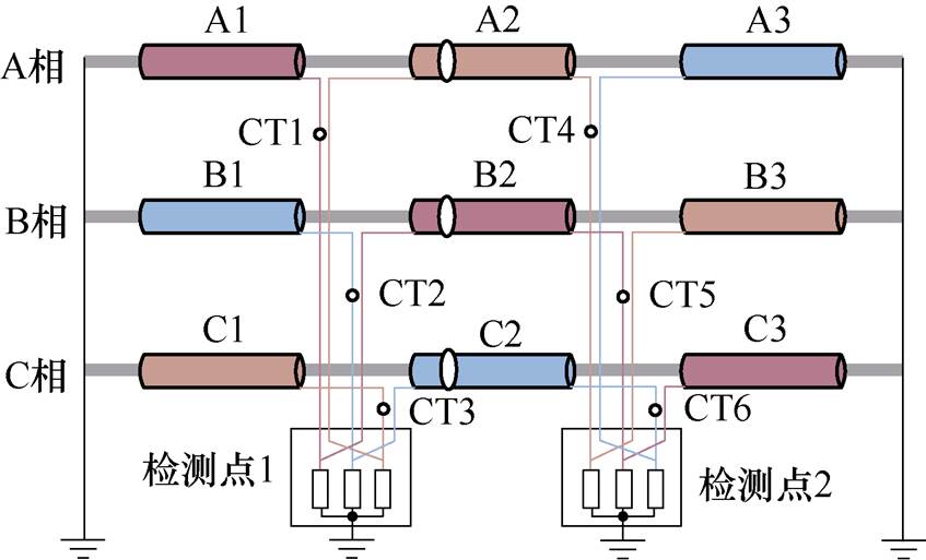
图1 护层接地电流在线监测系统
Fig.1 On-line monitoring system of sheath current
摘要 交叉互联高压电缆系统中的分布式护层电流检测对于护层接地故障诊断至关重要。为解决地下高压电缆不依赖外部时标的分布式护层电流传感时间同步问题,该文基于交叉互联高压电缆护层间的耦合关系,采用并联Smith预估补偿器提升时滞补偿效率,获取残差最小的时间偏置补偿时滞量,提出多护层电流传感器时滞误差的递归最小二乘跟踪方法,以电容电流短时不变为稳定判据,对实际测量时分布式护层电流传感器之间的时延进行估计和控制。该方法在220 kV高铁牵引变压器一次侧高压电缆分布式护层电流传感系统上进行了试验验证,验证结果表明,该方法收敛至最小残差值点,平均残差为0.30 A,准确时滞量为3.93 s,能实现分布式护层电流传感的时间同步。
关键词:高压电缆 交叉互联 护层电流 在线监测 时滞控制
地下高压电缆是城市电力系统的主动脉,对城市电网安全稳定运行至关重要[1]。近年来,由于外力破坏、接头安装质量、外绝缘劣化等引起的高压电缆单相接地故障频繁发生[2-3]。护层接地故障是单相接地故障的主要诱因之一,护层接地故障会导致护层电流异常、载流量下降和绝缘加速老化,在长期运行过程中,最终引发单相接地故障[4-5]。因此,提前检测电缆护层接地故障对防止高压电缆进一步损伤具有重要意义[6-9]。
护层电流可反映护层接地状态,受到工业界和学术界越来越多的关注。在日常巡检中,一般采用钳形电流表单点检测护层电流,利用护层电流幅值、护层电流与相电流比值、3个护层回路的护层电流相对值判别护层接地故障[10-13]。文献[10]讨论了利用交叉互联高压电缆的护层电流幅值进行护层对地故障检测的可行性。文献[11]提出了以护层电流与相电流之比为判据的交叉互联电缆系统分布式护层电流在线监测方法,用于检测单个金属护层回路开路故障、电缆接地箱进水、金属护层间绝缘击穿三种典型护层对地故障。文献[13]扩展了文献[12]所提出的方法用于线芯换位护层不换位的高压电缆系统。文献[14]中考虑了护层电流随相电流的波动,提出了日最大负荷电流时刻护层电流与相电流的比值作为接地状态指标,提升了检测的准确性。护层电流是感应电流与泄漏电流的相量和,受护层拓扑及耦合参数的影响,交叉互联高压电缆系统中的护层电流相量和分布式护层电流之间的相量差是接地故障更好的状态参数。文献[15]的研究表明,同回路两端护层电流相量差既可以区分正常和故障状态,又可以区分同回路、不同位置高压电缆护层保护器金属性接地故障。与正常时相比,护层电流相量差相位对金属性接地故障和低阻抗故障敏感。然而,受分布式护层电流测量系统时间同步的制约,测量的时延导致护层电流的相量或其差值很难准确计算。
分布式护层电流的同步测量是护层电流相量分析及护层接地故障诊断的前提条件。目前,护层电流传感器主要采用两种同步方法:本地网络同步和卫星时间传输[16-18]。文献[16]提出了一种基于本地光纤网络同步的在线监测方法,通过护层电流的分布式传感来测量交叉互联电缆的相对介质损耗,但并未考虑采样电路和局部网络的时延。文献[17-18]提出了一种基于全球定位系统时间传输的行波法,通过护层电流监测高压电缆单相接地故障定位,该方法不考虑分布式传感器的触发时延不一致。在实际的地下电缆测量系统中,网络不可用和卫星信号丢失的情况时有发生。此外,同步方法的硬件成本是护层电流同步传感的主要制约因素。
为实现不依赖外时标的分布式护层电流传感系统的时间同步,本文首先构建了交叉互联高压电缆护层间的耦合关系,再引入并联Smith预估器补偿同护层回路相邻护层电流检测点的时滞误差;然后提出多护层电流传感器时滞误差的递归最小二乘跟踪方法,利用电容电流短时不变作为稳定判据,获得残差最小的时间偏置补偿时滞量,并得到实际测量时分布式护层电流传感器间的时延。
本节首先构建交叉互联高压电缆护层电流分布式在线监测系统的模型,然后建立泄漏电流分量和感应电流分量的等效电路模型,并给出护层电流计算方法,接着根据交叉互联高压电缆同护层回路不同检测点护层电流的电磁耦合关系,推导同回路临近检测点护层电流差值的关系式。
长高压电缆线路一般采用两端直接接地,中间交叉互联接地的方式,包含若干个交叉互联段,护层接地电流在线监测系统如图1所示,每个交叉互联段包含三相九段高压电缆,每小段通过护层换位实现交叉互联,护层连接成三个回路:A1—B2—C3、B1—C2—A3、C1—A2—B3。
交叉互联段是高压电缆护层电流检测的基本单元,为实现护层电流的分布式同步在线监测,采用两组6个传感器分别安装在检测点1和检测点2的护层与接地箱连接线上,测量某时间段内不同回路相邻检测点的护层电流。测量开始前两个检测点设定初始时间,但是在测量的过程中,由于硬件时延和软件时延等原因会存在一定的采样时间差。

图1 护层接地电流在线监测系统
Fig.1 On-line monitoring system of sheath current
对于理想时间同步离散采样系统,6个护层电流传感器测量的护层电流耦合关系为
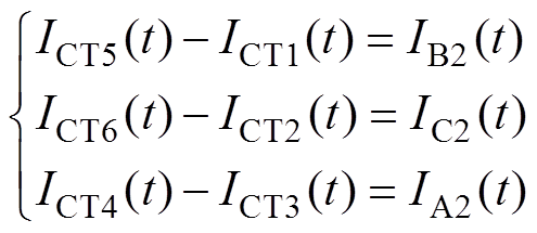 (1)
(1)
而实际非时间同步离散采样系统,6个护层电流传感器测量的护层电流耦合关系为
 (2)
(2)
式中, 、
、 、
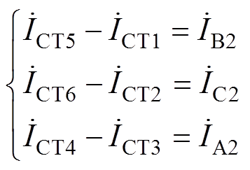
、 分别为三个护层回路相邻检测点获取的护层电流瞬时值的差值。
交叉互联高压电缆在运行时,线芯接高压,金属护层接地[19]。交叉互联高压电缆护层接地电流的容性耦合回路如图2所示,泄漏电流经过主绝缘和金属护层流向两端直接接地点。 为通过每小段(X=A, B, C;n=1, 2, 3)主绝缘的泄漏电流,
 、
、 分别为第X相第n小段高压电缆流入向左、右侧直接接地点的泄漏电流分量。
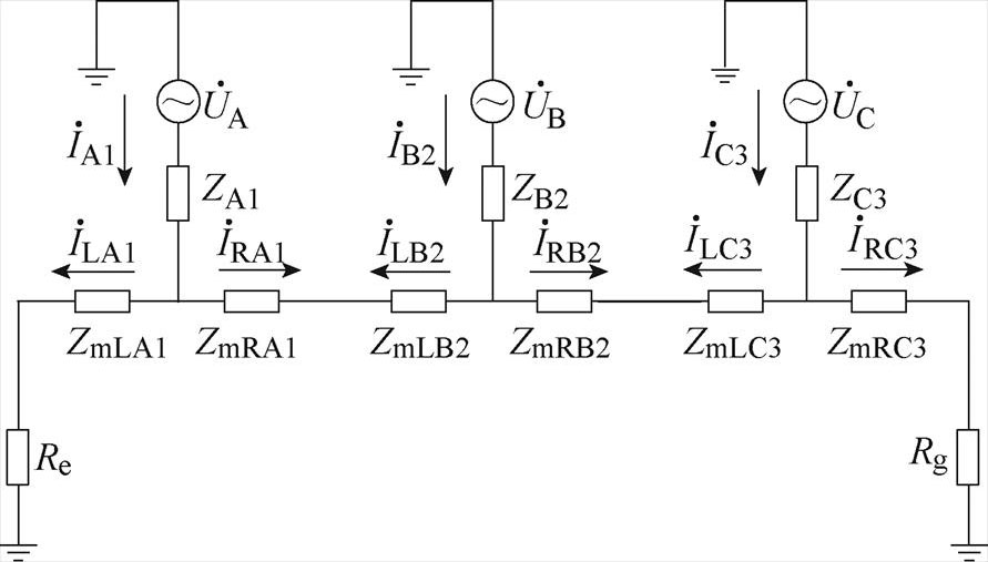
图2 交叉互联高压电缆护层接地电流的容性耦合回路
Fig.2 The capacitive coupling relationship of grounding current in cross-bonding HV cable systems
交叉互联高压电缆的主绝缘材料是交联聚乙烯,因绝缘阻抗的数量级为1015 W/m,远大于护层阻抗的10-2~10 W/m,泄漏电流的阻性分量相较于容性分量小的多,可以忽略[20],泄漏电流主要成分为电容电流,表示为
 (3)
(3)
式中, 、
、 、
、 分别为A、B、C相的线芯电压;l1、l2、l3分别为第1、2、3段的电缆长度;C为单位长度的等效电容,即
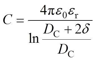 (4)
(4)
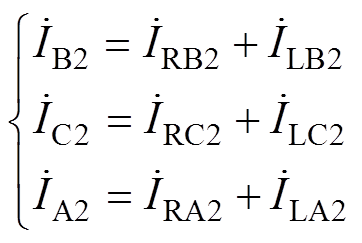
式中,e0为真空介电常数;er为相对介电常数,XLPE的相对介电常数为2.3;DC为电缆线芯的直径;d 为绝缘体厚度。如图2所示,假设向右为正方向,交叉互联中间段电缆的电容电流可表示为流向右侧直接接地点的电容电流与流向左侧直接接地点的电容电流相量和,即
 (5)
(5)
式中, 、
、 、
、 分别为A2、B2、C2段高压电缆电容电流相量;
 、
、 、
、 分别为A2、B2、C2段高压电缆流向右侧直接接地点的电容电流相量;
 、
、 、
、 分别为A2、B2、C2段高压电缆流向左侧直接接地点的电容电流相量。
高压电缆运行时,负载电流会在电缆周围产生交变磁场,磁通与金属护层交链,变化的磁通在金属护层上产生感应电压。交叉互联高压电缆护层接地电流的感应耦合回路如图3所示,由于每个交叉互联电缆系统两端均直接接地,金属护层会与大地之间形成闭合回路,在理想情况下,经过交叉互联后各支路金属护层中的感应电压之和为零,其环流也为零[21]。
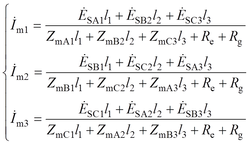
实际运行中的电缆电感参数不对称和线芯电流不平衡都会导致各支路金属护层中的感应电压之和不为零,护层回路将产生感应电流,表示为
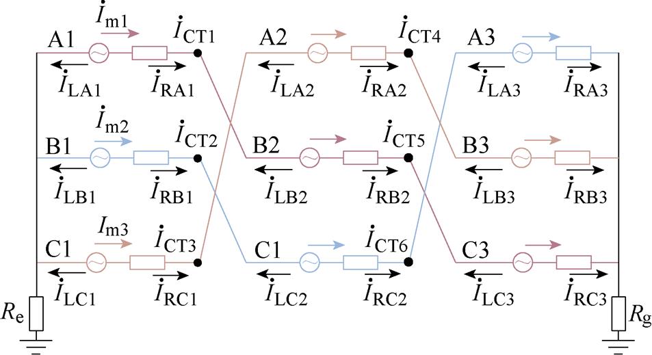
图3 交叉互联高压电缆护层接地电流的感应耦合回路
Fig.3 Induction coupling relationship of grounding current of cross-bonding high voltage cable sheath
 (6)
(6)
式中, 、
、 、
、 分别为回路1、2、3的感应电流;
 为小段电缆护层单位长度的感应电压;ZmXn为小段电缆护层单位长度的阻抗;Re和Rg分别为电缆电源侧和负载侧的接地电阻。护层感应电压与电缆的长度、单位长度电感、负载电流呈正相关。电缆线芯与金属护层的互阻抗为
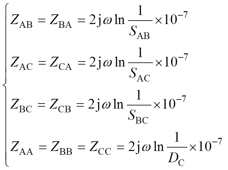 (7)
(7)
某相金属护层对其他相金属护层的互阻抗为
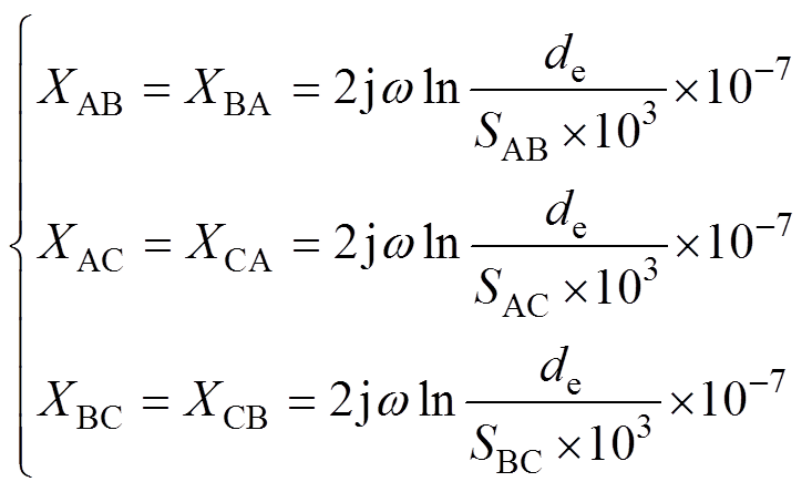 (8)
(8)
式中,Zxy为x相线芯对y相护层的单位长度互阻抗,x, y=A, B, C;Sxy为x相电缆与y相电缆中心间距;de为大地等值深度。
由基尔霍夫电压定律可得三护层回路的感应电压为

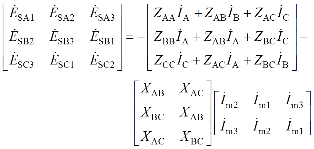 (9)
(9)
高压电缆在正弦稳态带纯感性负载情况下,A1段护层电流中泄漏电流分量和感应电流分量的耦合关系如图4所示, 、
、 、
、 为高压电缆带纯感性负载下相电流相量。根据叠加原理,护层电流相量等于电容电流与感应电流的相量和,电容电流分量超前线芯电压90°,线芯电流产生的交变磁场与护层回路耦合,产生感应电动势,进而产生感应电流,感应电流分量超前线芯电流90°。实际测量的护层电流与泄漏电流分量和感应电流分量的耦合关系为
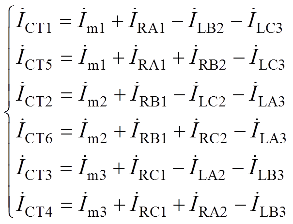 (10)
(10)
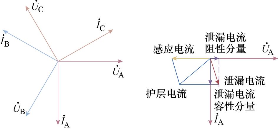
(a)线芯电压和电流的相量关系(b)护层电流耦合关系示意图
图4 高压电缆带纯感性负载时的护层电流耦合关系
Fig.4 Coupling elements of sheath current in HV cable supplying inductive load
根据电流连续性原理,在无时延采样情况下,同一护层回路中检测点1和检测点2的感应电流大小相等,联立式(5)、式(6)和式(10)可得护层回路相邻检测点的护层电流差值为两个检测点所夹电缆的电容电流,表示为
 (11)
(11)
实际运行中,电缆线芯电压短时波动很小,电容电流短时不变,可作为时滞控制的稳定点。实现时采用式(11)定义的,同护层回路相邻电流传感器所测电流信号差值相量对时间的变化率小于1%作为电容电流稳定判据。
同护层回路相邻电流传感器所测电流信号同频,相位差可表示为
 (12)
(12)
式中,t 为同护层回路相邻电流传感器所测电流信号时间差;q 为相位差;f为频率,f=50 Hz。
由于软硬件时延的客观存在,检测点1与检测点2的电流传感器之间存在着采样时间差t,则检测点2护层电流纯滞后部分的传递函数为e-ts。以护层回路1中的电流传感器CT1和CT5为例,检测点2的时滞会导致不能正确分析测得的电流相量,需要补偿检测点2电流信号的时间延迟[22]。Smith预估器原理如图5所示,引入一个与控制器并联的Smith预估器补偿时延t。两点测量的护层电流电磁耦合关系如式(10)所示,由拉普拉斯变换可得CT5处传递函数为G(s)=G5(s)e-ts,无时滞部分G5(s)为
 (13)
(13)

图5 Smith预估器原理
Fig.5 Principle diagram of smith predictor
补偿前系统的传递函数为
 (14)
(14)
Smith预估器可以使被控量的时间延迟反映到调节器并使之动作,G5(s)(1-e-ts)为Smith预估补偿器传递函数。补偿后,系统的闭环传递函数为
 (15)
(15)
时滞控制框图如图6所示,实际采样系统安装在3个回路上,3个Smith预估器为并联控制结构。引入Smith预估器后,e-ts在闭合回路外,即网络时滞在闭环控制之外,实现了时延补偿控制。6个电流传感器所测数据为周期性电流信号,两个检测点之间的时间延迟为t,同一回路相邻传感器所测电流差为实测值,相应回路第二段电容电流为期望值,以采样点为周期迭代更新实测值,再与期望值对比得出相应残差[23],即可得出时间延迟。
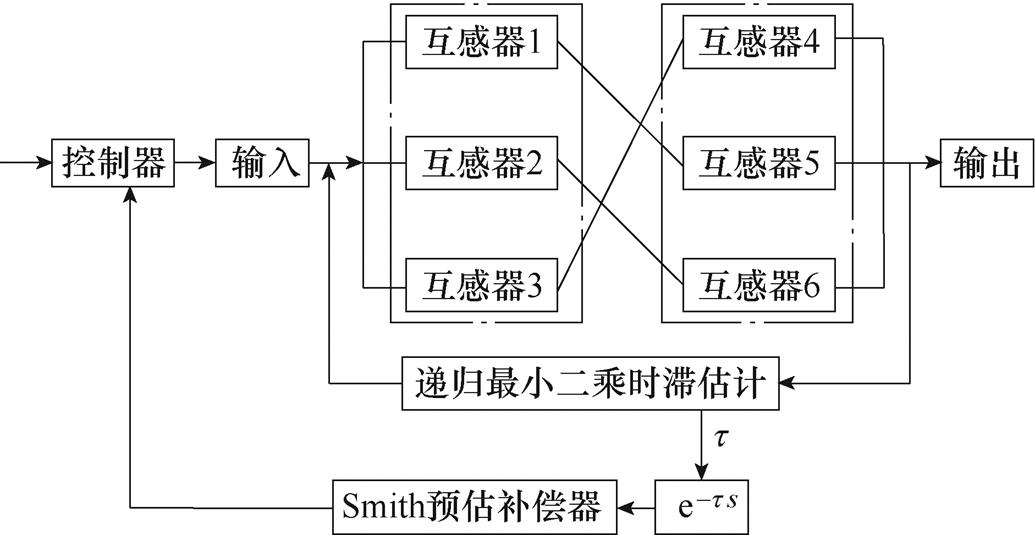
图6 时滞控制框图
Fig.6 Time-delay control block diagram
设6个护层电流传感器CT1、CT2、CT3、CT4、CT5、CT6所测离散时刻电流矩阵分别为xA[n]、xB[n]、xC[n]、xD[n]、xE[n]、xF[n],3个回路第二段电缆B2、C2、A2离散时刻电容电流值分别为yB2[n]、yC2[n]、yA2[n],i为离散时刻偏置量。
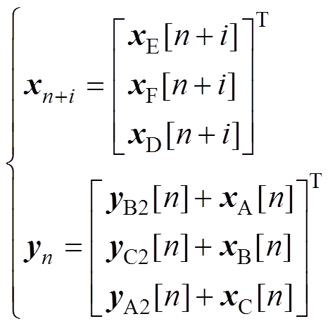 (16)
(16)
方法流程如图7所示,利用递归最小二乘法求出时间延迟后,为消除时延影响,在系统反馈控制的基础上,引入预估补偿环节,并与控制器反向并联,得到了已消除时滞部分的被控量,再反馈到控制器,使闭环特征方程不含纯滞后项。在进行时滞估计时,两个检测点六组传感器分别选取5个周期的电流瞬时值,xn+i代表每个回路检测点2的护层电流瞬时值,其值会随着迭代次数一直更新,yn代表每个回路检测点1的护层电流瞬时值与电容电流瞬时值之和,其值保持不变。
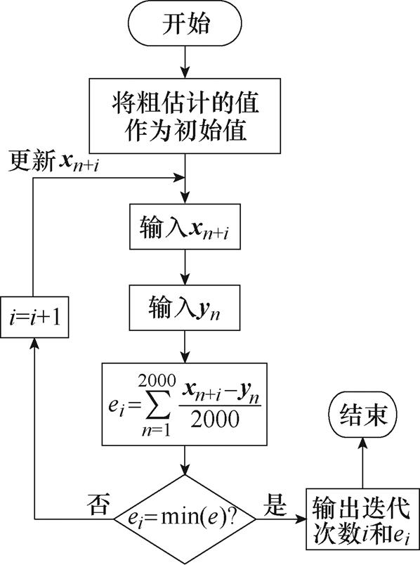
图7 方法流程
Fig.7 Flow chart of the proposed method
在不同的时间偏置量下,同一回路传感器所测护层电流差值与实际电容电流之间存在不同的残差,如果某一时刻3个回路的残差均最小[24],则认为此时刻的时间偏置量i是检测点2滞后检测点1的时间。
 (17)
(17)
式中,ei分别为回路i在不同时滞偏置量下,护层电流差值的瞬时值与电容电流瞬时值之间的平均残差。
本方法在某220 kV高铁牵引变压器一次侧交叉互联高压电缆系统上做了试验验证,现场测量环境如图8所示。数据采集系统由两套数据采集卡和计算机组成,型号分别为Tiepie HandyScope 6和HP Z99,采样率为20 kS/s,采样时间为300 s。
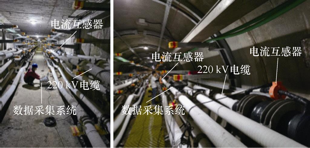
图8 现场测试
Fig.8 Field test diagram
护层上的6个电流传感器TA1~TA6安装在如图1所示的中间接头与交叉互联接地箱连接的同轴电缆上,电流互感器为铁磁式,电压比为100/5,3个电流互感器为一组分别经连接线与数据采集系统的3个通道相连。测试分三步,先在地面上同步两台计算机,然后约定采样开始时间,最后在地下电缆通道安装互感器,连接至采集系统后,按照约定时间采样。
时间同步前的护层电流瞬时值如图9所示,检测点1中TA1、TA2、TA3的波形峰值是基本同步的,而检测点1和检测点2采集的波形峰值是不同步的。

(a)TA1

(b)TA2

(c)TA3

(d)TA4

(e)TA5

(f)TA6
图9 时间同步前的护层电流瞬时值
Fig.9 The instantaneous value of sheath current before time synchronization
通过第2节所述时滞估计与控制方法对护层电流进行时间同步后的护层电流瞬时值如图10所示,此时检测点1与检测点2的波形峰值处于同步状态。各回路护层电流差值与电容电流对比选取的数据为从测量开始后第52 s之后100 ms的护层电流瞬时值,所选取时间段护层电流瞬时值的局部放大波形如图10所示。

(a)TA1

(b)TA2

(c)TA3

(d)TA4

(e)TA5

(f)TA6
图10 时间同步后的护层电流瞬时值
Fig.10 The instantaneous value of sheath current after time synchronization
采用第2节所述递归最小二乘时滞估计法,选取时间段内时间同步的效果如图11所示,3个护层回路相邻检测点之间护层电流差值与对应回路第二段电容电流吻合,符合式(11)推导的无时延情况下护层电流差值与电容电流关系,说明本方法实现了多传感器间的时间同步。
本文试验的场景选择功率因素波动较大的高铁牵引负荷,高铁牵引负荷的功率因素受列车运行状态(加速、减速、过分相和再生制动等)及牵引变压器二次侧与接触网连接方式的影响[25],从图10和图11的实测结果看,在列车运行状态不发生改变时,可认为“电容电流稳定”,时间尺度在s级,50~1 000个周波。对于功率因素波动不大的负荷,“电容电流稳定”的区域较易选择,时间尺度缩小至ms级,50个周波以内。IA2(t)、IB2(t)、IC2(t)分别为A2、B2、C2段电容电流的瞬时值,它们之间的相位差为120°,与护层电流差值对比的是离散采样的时间点,一个采样点代表0.000 05 s。
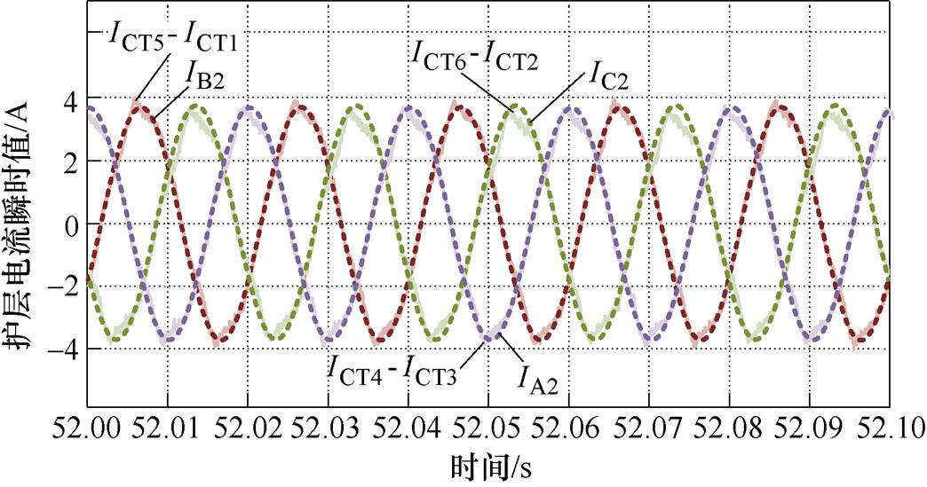
图11 各回路护层电流差值与电容电流对比
Fig.11 Comparison of sheath current difference and capacitance current of each circuit sheath
本文的试验线路未发生护层接地故障,回路1同步前后的护层电流相量差相位分别为36.9°和133.2°,回路2同步前后的护层电流相量差相位分别为74.7°和94.5°,回路3同步前后的护层电流相量差相位分别为23.4°和143.1°。文献[12]研究了交叉互联高压电缆护层保护器216 W 接地故障工况,护层电流相量差相位的偏差范围为9.4°~17.5°。因此,时间不同步对护层电流相量差相位有影响,不准确的护层电流相量差相位可能导致护层接地故障的误判。
52.0~52.1 s之间有2 000个采样点,每条回路取各自的前5个过零点进行对比,各回路过零点对应采样点的护层电流差值与所夹电容电流值见表1。由表1可知,各个过零点所对应采样点的护层电流差值与所夹电容电流值都相差很小,相差最大值为0.297 A,相差最小值为0.002 A。
通过递归最小二乘法所得局部残差收敛如图12所示,第218次迭代为局部范围内第一个残差最小值收敛点,每隔400次迭代会出现一个周期内的残差收敛点。
表1 各回路过零点对应采样点的护层电流差值与所夹电容电流值
Tab.1 Difference of sheath current and value of clamped capacitance current at sampling points corresponding to zero-crossing points of each loop
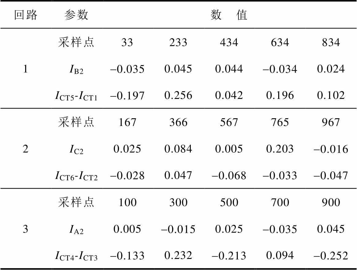
回路参数数 值 1采样点33233434634834 IB2-0.0350.0450.044-0.0340.024 ICT5-ICT1-0.1970.2560.0420.1960.102 2采样点167366567765967 IC20.0250.0840.0050.203-0.016 ICT6-ICT2-0.0280.047-0.068-0.033-0.047 3采样点100300500700900 IA20.005-0.0150.025-0.0350.045 ICT4-ICT3-0.1330.232-0.2130.094-0.252
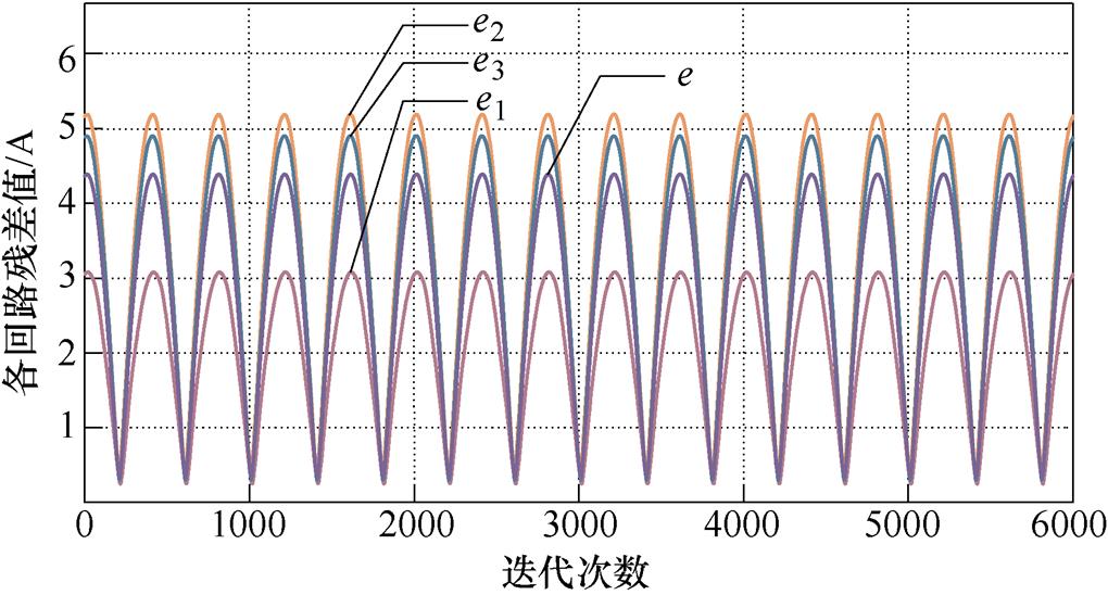
图12 局部残差收敛
Fig.12 Local residual error convergence
在局部范围内无法得知所求收敛点是否为全局范围内最小残差值,且以迭代次数为单位平移时滞偏置量数据量过大,运算速度缓慢。引入Smith预估补偿器以周期为单位平移时滞补偿量,提升补偿效率,全局遍历的递归最小二乘法能够提升补偿精度,所得整体范围内的残差收敛如图13所示。
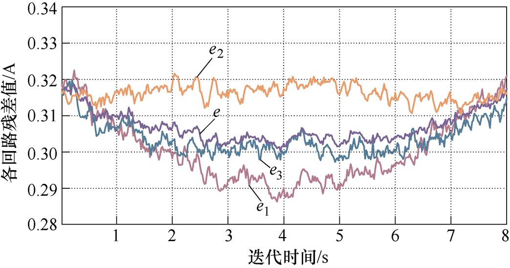
图13 整体残差收敛
Fig.13 Overall residual error convergence
时滞估计的参考标准为3个回路的平均残差,每个回路的最小残差都处于0.28~0.33 A之间,e1和e3在8 s内有先下降后上升的趋势,e1和e3都在迭代时间为3.94 s时最小,e2趋势与e1、e3不同,但不影响3个回路的平均残差e在迭代时间为3.94 s时最小。Smith预估器补偿过程如图14所示,当Smith预估补偿器第197次平移,得出时滞偏置量为3.94 s时整体范围内的残差值最小,为0.3 A。
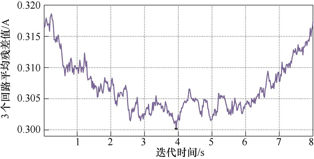
图14 Smith预估器补偿过程
Fig.14 Smith predictor compensation process
1)通过Smith时滞控制与递归最小二乘时滞估计可实现对护层电流的时间同步,时间同步后同一回路相邻护层电流差值的瞬时值与所夹电容电流瞬时值相同,符合时间同步时的护层电流差值传递 函数。
2)时间不同步对护层电流相量差有影响,回路1同步前后的护层电流相量差相位分别为36.9°和133.2°,回路2同步前后的护层电流相量差相位分别为74.7°和94.5°,回路3同步前后的护层电流相量差相位分别为23.4°和143.1°,时间不同步时,护层电流相量差不准确,将影响护层接地状态评估。
3)全局范围内的最小平均残差值为0.3 A,此时的迭代时间为3.94 s,即当时滞量为3.94 s时3个回路最符合护层电流差值传递函数,补偿3.94 s时滞量后实现时间同步。
参考文献
[1] Zhou Chengke, Yi Huajie, Dong Xiang. Review of recent research towards power cable life cycle management[J]. High Voltage, 2017, 2(3): 179-187.
[2] 陈杰, 吴世林, 胡丽斌, 等. 退役高压电缆附件绝缘状态及理化性能分析[J]. 电工技术学报, 2021, 36(12): 2650-2658.
Chen Jie, Wu Shilin, Hu Libin, et al. Analysis of insulation state and physicochemical property of retired high-voltage cable accessories[J]. Transactions of China Electrotechnical Society, 2021, 36(12): 2650-2658.
[3] Tang Zeyang, Zhou Chengke, Jiang Wei, et al. Analysis of significant factors on cable failure using the COX proportional hazard model[J]. IEEE Transa- ctions on Power Delivery, 2014, 29(2): 951-957.
[4] 唐进, 张姝, 林圣, 等. 计及金属护层结构的电缆单端故障测距方法[J]. 中国电机工程学报, 2016, 36(6): 1748-1756, 1798.
Tang Jin, Zhang Shu, Lin Sheng, et al. Single- terminal fault locating method of cables considering the metal sheath structure[J]. Proceedings of the CSEE, 2016, 36(6): 1748-1756, 1798.
[5] 严有祥, 朱婷, 张那明, 等. 交直流电缆共沟敷设电磁环境影响因素[J]. 电工技术学报, 2022, 37(6): 1329-1337.
Yan Youxiang, Zhu Ting, Zhang Naming, et al. The influence factors of electromagnetic environment in the tunnels with DC cables and AC cables[J]. Transactions of China Electrotechnical Society, 2022, 37(6): 1329-1337.
[6] Li Shengtao, Li Jianying. Condition monitoring and diagnosis of power equipment: review and pro- spective[J]. High Voltage, 2017, 2(2): 82-91.
[7] 单秉亮, 李舒宁, 杨霄, 等. XLPE配电电缆缺陷诊断与定位技术面临的关键问题[J]. 电工技术学报, 2021, 36(22): 4809-4819.
Shan Bingliang, Li Shuning, Yang Xiao, et al. Key problems faced by defect diagnosis and location technologies for XLPE distribution cables[J]. Transa- ctions of China Electrotechnical Society, 2021, 36(22): 4809-4819.
[8] 贾科, 施志明, 张旸, 等. 基于电缆早期故障区段定位的柔性直流配电系统保护方法[J]. 电力系统自动化, 2023, 47(4): 163-171.
Jia Ke, Shi Zhiming, Zhang Yang, et al. Protection method of flexible DC distribution system based on cable incipient fault section location[J]. Automation of Electric Power Systems, 2023, 47(4): 163-171.
[9] 王昊月, 李成榕, 王伟, 等. 高压频域介电谱诊断XLPE电缆局部绝缘老化缺陷的研究[J]. 电工技术学报, 2022, 37(6): 1542-1553.
Wang Haoyue, Li Chengrong, Wang Wei, et al. Local aging diagnosis of XLPE cables using high voltage frequency domain dielectric spectroscopy[J]. Transa- ctions of China Electrotechnical Society, 2022, 37(6): 1542-1553.
[10] Marzinotto M, Mazzanti G. The feasibility of cable sheath fault detection by monitoring sheath-to-ground currents at the ends of cross-bonding sections[J]. IEEE Transactions on Industry Applications, 2015, 51(6): 5376-5384.
[11] Dong Xiang, Yang Yang, Zhou Chengke, et al. Online monitoring and diagnosis of HV cable faults by sheath system currents[J]. IEEE Transactions on Power Delivery, 2017, 32(5): 2281-2290.
[12] Shokry M A, Khamlichi A, Garnacho F, et al. Detection and localization of defects in cable sheath of cross bonding configuration by sheath currents[J]. IEEE Transactions on Power Delivery, 2019, 34(4): 1401-1411.
[13] Li Zhonglei, Du Boxue, Li Wang. Evaluation of high-voltage AC cable grounding systems based on the real-time monitoring and theoretical calculation of grounding currents[J]. High Voltage, 2018, 3(1): 38-43.
[14] Wang Yilin, Ye Hao, Zhang Tongshuai, et al. A data mining method based on unsupervised learning and spatiotemporal analysis for sheath current monito- ring[J]. Neurocomputing, 2019, 352(4): 54-63.
[15] 刘福源, 王航, 夏湛然, 等. 交叉互联高压电缆护层保护器故障对同回路两端护层电流相量差的影响[J]. 高电压技术, 2023, 49(3): 1244-1253.
Liu Fuyuan, Wang Hang, Xia Zhanran, et al. Influence of the sheath voltage limiter fault on the sheath current phasor difference between the two ends in the same sheath loop in cross-bonded HV cables[J]. High Voltage Engineering, 2023, 49(3): 1244-1253.
[16] Yang Yang, Hepburn D M, Zhou Chengke, et al. On-line monitoring of relative dielectric losses in cross-bonded cables using sheath currents[J]. IEEE Transactions on Dielectrics and Electrical Insulation, 2017, 24(5): 2677-2685.
[17] Li Mingzhen, Zhou Chengke, Zhou Wenjun, et al. A novel fault location method for a cross-bonded HV cable system based on sheath current monitoring[J]. Sensors, 2018, 18(10): 3356-3375.
[18] Li Mingzhen, Liu Jianming, Zhu Tao, et al. A novel traveling-wave-based method improved by unsuper- vised learning for fault location of power cables via sheath current monitoring[J]. Sensors, 2019, 19(9): 2083-2107.
[19] 徐星, 陈向荣, 杜振东, 等. 基于非解耦节点导纳矩阵的随桥电缆接地方式研究[J]. 电工技术学报, 2021, 36(17): 3664-3674.
Xu Xing, Chen Xiangrong, Du Zhendong, et al. Study on bridge-cable grounding system based on the non-decoupling nodal admittance matrix[J]. Transa- ctions of China Electrotechnical Society, 2021, 36(17): 3664-3674.
[20] 李根, 王航, 刘海康, 等. 基于逻辑回归的高压电缆交叉互联接地系统缺陷分类识别方法[J]. 高电压技术, 2021, 47(10): 3674-3683.
Li Gen, Wang Hang, Liu Haikang, et al. Classification and identification method of grounding system defects in cross-bonded HV cables based on logistic regression[J]. High Voltage Engineering, 2021, 47(10): 3674-3683.
[21] Shaban M, Salam M A, Ang S P, et al. Induced sheath voltage in power cables: a review[J]. Renewable and Sustainable Energy Reviews, 2016, 62(1): 1236- 1251.
[22] 马燕峰, 霍亚欣, 李鑫, 等. 考虑时滞影响的双馈风电场广域附加阻尼控制器设计[J]. 电工技术学报, 2020, 35(1): 158-166.
Ma Yanfeng, Huo Yaxin, Li Xin, et al. Design of wide area additional damping controller for doubly fed wind farms considering time delays[J]. Transactions of China Electrotechnical Society, 2020, 35(1): 158- 166.
[23] 薛安成, 张兆阳, 毕天姝. 基于自适应抗差最小二乘的线路正序参数在线辨识方法[J]. 电工技术学报, 2015, 30(8): 202-209.
Xue Ancheng, Zhang Zhaoyang, Bi Tianshu. Online identification of transmission line positive-sequence parameters based on adaptive robust least squares[J]. Transactions of China Electrotechnical Society, 2015, 30(8): 202-209.
[24] 谢文超, 赵延明, 方紫微, 等. 带可变遗忘因子递推最小二乘法的超级电容模组等效模型参数辨识方法[J]. 电工技术学报, 2021, 36(5): 996-1005.
Xie Wenchao, Zhao Yanming, Fang Ziwei, et al. Variable forgetting factor recursive least squales based parameter identification method for the equivalent circuit model of the supercapacitor cell module[J]. Transactions of China Electrotechnical Society, 2021, 36(5): 996-1005.
[25] 程鹏, 刘文泉, 陈冲, 等. 面向电气化铁路牵引供电的光伏发电分相电流控制策略[J]. 电力系统自动化, 2022, 46(19): 145-153.
Cheng Peng, Liu Wenquan, Chen Chong, et al. Individual phase current control strategy of photo- voltaic power generation for traction power supply of electrified railway[J]. Automation of Electric Power Systems, 2022, 46(19): 145-153.
Time Delay Control Method for Distributed Sheath Current Sensing System of Underground Cross-Bonding High Voltage Cable
Abstract Underground HV (High Voltage) cable is the backbone of modern urban power systems. In the last decades, the sheath-to-ground fault is becoming one of the main modes contributing to the single-phase grounding fault. Sheath current sensing is widely adopted in field tests to detect the sheath-to-ground fault. However, the synchronization of distributed sheath current sensing based on GPS (Global Position System) or Beidou is unstable because the time transfer tag is usually unavailable in underground cable tunnels. Therefore, a time delay control method based on the Smith predictor compensator and recursive least squares method (RLSM) is proposed using the capacitive current as a reference of the measured sheath current in the same sheath loop.
Firstly, the architecture of the distributed sheath current sensing in HV cross-boned cable systems is introduced, and the formulation of the measured sheath current in the same sheath loop with time delay is deduced. Secondly, the electromagnetic coupling relationship between the sheath current and load current is modeled, and the phasor difference of the measured sheath current in the same sheath loop without time delay is formulated as the reference of the RLSM. Thirdly, the parallel Smith predictor is proposed to compensate for the time delay error of the adjacent sheath current detection points in the same sheath loop. Finally, a recursive least square tracking method for the time delay error of the multi-sheath current sensor is proposed to obtain the time delay with the minimum residual.
The proposed method is verified by field tests of a 220 kV cross-boned cable supplying the high-speed traction transformer. The results show that the waveform of capacitive current, which is the reference of RLSM, inosculates well with the difference of the measured sheath current in the same sheath loop after using the proposed method. The maximum difference is 0.297 A, and the minimum difference is 0.002 A. Moreover, the reference standard for time delay estimation is the average residual of the three loops, and the minimum residual of each loop is between 0.28~0.33 A. In addition, the Smith predictor is translated for the 197th time, and the residual value in the overall range is the smallest when the time delay offset is 3.94 s, which is 0.3 A.
The following conclusions can be drawn from the experiment: (1) The instantaneous current difference between adjacent sheaths in the same loop inosculates with the instantaneous capacitor current after using the proposed method, which implies the synchronization of distributed sheath current sensing. (2) When distributed sheath current sensing is asynchronous, the current phasor difference of the sheath is not accurate, which will affect the evaluation of the grounding state of the sheath. (3) The proposed method converges to the minimum average residual value of 0.3 A in the global range, and the time delay is 3.94 s.
keywords:HV cable, cross-bonding, sheath current, online monitoring, time-delay control
中图分类号:TM274
DOI: 10.19595/j.cnki.1000-6753.tces.222116
湖北省电力公司科技项目(SGTYHT/21-JS-223)和湖北工业大学科研启动基金项目(HSQD2020020)资助。
收稿日期 2022-11-08
改稿日期 2022-12-26
周莎莎 女,2000年生,硕士研究生,研究方向为高压电缆在线监测系统的时滞和误差控制。E-mail: zhou.shasha@hbut.edu.cn
王 航 男,1989年生,博士,硕士生导师,研究方向为电力电缆状态检测与新能源并网。E-mail: wanghang@whu.edu.cn(通信作者)
(编辑 陈 诚)