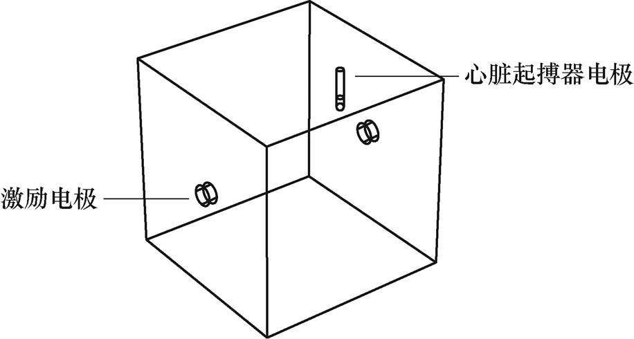
图1 生物电阻抗测量模型
Fig.1 Bio-electrical impedance measurement model
摘要 全球范围内佩戴心脏植入电子设备的患者日益增加,采用生物电阻抗技术进行病理检测,可能会对心脏植入电子设备患者产生干扰。该文建立生物电阻抗交流激励系统及心脏起搏电极仿真模型,完成胸腔生物阻抗检测技术对心脏起搏器电磁干扰的安全性研究。仿真研究表明,胸腔生物阻抗测量引起的电压干扰超过了ISO 14117标准中定义的最大阈值,且干扰水平随着生物阻抗激励信号的频率和电极位置的不同而变化,并且组织电特性也会对干扰水平产生影响。生物电阻抗技术可能会对心脏植入电子设备存在潜在干扰,不建议在该人群中使用胸腔阻抗法进行检测。
关键词:心脏起搏器 胸腔电阻抗 感应电动势 设备干扰
近年来,由于社会老龄化日趋严重以及环境等因素的影响,心血管疾病发病率逐年递增。我国心脑血管病患人数约为3.3亿人,其中冠心病1 100万人,肺原性心脏病500万人,心力衰竭890万人,风湿性心脏病250万人,先天性心脏病200万人[1]。对于心脏疾病的治疗手段,临床需求较大。心脏植入式电子设备在目前的医学指南促进下,获得了越来越多患者的选择。根据第25届全国介入心脏病学论坛发布的数据,2021年我国心脏起搏器植入量达9.9万台,同比增长15.1%。心脏植入电子设备内附多个微电路,容易受到磁共振成像、电外科、生物电阻抗等医疗设备的影响。
生物电阻抗技术通过电极施加不同频率的交变电信号激励,并测量身体产生的电压。疾病会改变生物组织的电学特性,从而影响组织传导交流电流的能力,最终体现在检测到不同特征的电压信号。确定好激励频率后,根据欧姆定律将电压信号除以电流信号,得到检测组织的阻抗。导电性能越好,得到的阻抗值越低;导电性能越差,得到的阻抗值越高。生物电阻抗技术对于血流的流动十分敏感,应用范围包括阻抗血流图(Impedance Cardiogram, ICG)、电阻抗断层成像(Electrical Impedance Tomo- graphy, EIT)技术、呼吸检测、生物电阻抗测量与分析等方面[2-4]。其中大部分分析方法已经应用在临床医学中。心阻抗血流图的基础是假设胸腔为介质均匀的规律圆柱体,通过向胸部注入高频交流信号,得到胸腔基础阻抗和变化阻抗,进而利用计算模型得到每搏量。电阻抗断层成像技术通过检测到的组织电压变化情况,对组织进行图像重构,得到待测组织内部电导率分布图像,目前在对肺实时监测方面发展迅速。人呼吸时胸廓的起伏变化,引起胸腹部电阻抗相应变化,通过采集相应的电压信号,通过呼吸曲线,能够对呼吸类疾病提前预警[5-7]。一些疾病的早期指标,如身体浮肿、体脂率改变、局部积液等,利用生物电阻抗技术或相关的电子设备可以提前检测到异常情况[8-10]。可见,生物电阻抗技术的临床应用价值广泛。
随着生物电阻抗技术的发展和应用,电磁干扰问题逐渐得到关注,由于潜在的干扰,心脏植入设备的制造商建议不要对心脏植入电子设备患者进行生物阻抗检测,出于谨慎考虑,美国食品和药物管理局(Food and Drug Administration, FDA)尚未批准可用于心脏植入电子设备患者的生物电阻抗设备。基于目前依赖植入式医疗设备维持正常生活的人数越来越多,生物电阻抗技术对植入式医疗设备的电磁干扰问题值得研究[11-13]。
X. Chabin等在200名心脏植入电子设备的患者中,进行生物阻抗测量,通过记录测量前后设备的电池电压、导线阻抗、起搏阈值及心电图的情况,未发现有明显变化。接下来的6~12个月的随访,也未发现植入心脏的电子设备出现异常,由此认为生物阻抗技术对佩戴心脏植入电子装置的患者没有显著干扰[14]。G. B. Ha等首次对基于生物阻抗技术的智能穿戴设备,如测量身体成分的智能称、智能手表和智能戒指对心脏植入式电子装置的可能干扰进行研究,研究结果显示这些可穿戴设备可能会干扰配置心脏植入式电子设备的患者,因为存在潜在的危险,所以不建议将可穿戴设备应用于这类人群中[15]。生物电阻抗技术对于心脏植入电子设备患者干扰的研究较少。迄今为止,胸腔阻抗法对这类患者影响的研究仍属于空白阶段,随着心脏ICG和胸腔EIT技术逐渐进入临床阶段,将激励电极置于胸腔表面的安全性问题得到关注,这种电极配置方式对心内植入电子设备患者的电磁干扰性问题亟待研究。
当电源中有电流通过时,就会在其周围产生交变磁场,放在变化磁通量中的导体,会产生电动势,即为感应电动势,感应电动势与磁通变化率成正比。通过实验发现,交流激励对组织的干扰情况受频率的影响而变化[16-17]。本文应用有限元软件模拟交流电流激励对心脏起搏器电极的电磁影响,通过电磁分析,计算心脏起搏器电极在生物电阻抗检测过程中的感应电动势,并使用ISO 14117国际标准评估胸腔生物阻抗技术与心脏起搏器的电磁兼容性水平。
生物电阻抗激励系统的核心部分为交变的高频信号,当电极通以一定频率的交流电时,在两电极之间会产生充满整个空间的交变电场。在激励注入过程中,电流会通过空间介质流动,电磁场随之变化[18]。电流不仅受到外加激励的约束控制,还受到空间电磁场的影响。本文通过有限元法对电磁场区域进行求解,计算心脏起搏器电极在不同激励下的空间电磁场。
忽略辐射的影响,假设电磁场为准稳场,电导率为线性同步的。生物电阻抗测量模型如图1所示。心脏起搏器包括脉冲发生器、导线和电极。其中脉冲发生器包含用于供电的电池和用于确定何时发出脉冲的电路。电线将发生器连接到心脏的各个部位,电极位于电线的末端。这里研究的是心脏起搏器电极上的感应电动势,所以忽略脉冲发生器和导线,只建立心脏起搏器电极模型。

图1 生物电阻抗测量模型
Fig.1 Bio-electrical impedance measurement model
系统在工作状态下,有限元区域满足Maxwell方程组关系,推导过程[19-20]如下
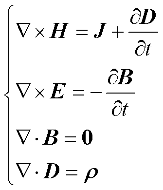 (1)
(1)
式中, 表示泊松算子;
 为传导电流密度;
 为磁场强度;
 为电场强度;
 为磁通密度;
 为电位移场;
 为电荷密度。根据介质的特性,满足如下关系
 (2)
(2)
式中, 为介质的介电常数;
 为磁导率;
为磁导率; 为电导率。式(2)为电磁场的辅助方程。
施加交变激励,求解域的电场强度可表示为
 (3)
(3)
引入边界电位 ,则有
,则有
 (4)
(4)
将式(3)和式(4)与麦克斯韦方程组结合得到
 (5)
(5)
散度形式为
 (6)
(6)
通常激励频率比较低且介电常数较小,则式(6)可以简写为
 (7)
(7)
为了保护心脏起搏器佩戴者免于暴露电磁干扰源的危险,国际上已有很多指导建议,实际上电磁场也会对设备产生影响,表现在心脏起搏器末端感应电动势信号幅度的波动。本文采用的是FDA认可的产品评估标准——ISO 14117: 2019《有源植入式医疗设备电磁兼容性的EMC测试协议》。协议规定了电压幅值波动安全限值,激励频率为f,当3 kHz<f<167 kHz时,线性增加最大电压幅值为6 mV/kHz;当167 kHz<f<1 000 kHz时,最大电压幅值保持在1 V[21]。本文通过COMSOL有限元分析软件计算起搏器电极电压,确定利用生物阻抗技术在胸腔检测期间对心脏起搏器的干扰水平。
起搏器包含1~3根导线。单线起搏器连接到右心室,双线起搏器连接到右心室和右心房,三线起搏器连接到一个心房和两个心室。在单线模式下,起搏器终端置于心脏内部,它实际上由阴极和阳极两个电极组成。电极通常由钛或者钛合金材料构成,钛材料的相对磁导率为1,电导率为7.407×10⁵ S/m,相对介电常数为1。电极之间连接材料为聚氨酯,电导率为0,相对介电常数为4。心脏位于胸腔中部偏左下方,横膈之上,第二根肋骨和第五根肋骨之间,体积相当于一个拳头大小。本文以单线起搏器为例,设定其安置在右心室,其电极位置应置于心脏偏右下侧。在配置胸腔电阻抗检测电极时既要避开隔膜的影响,又能够全面反映胸腔内部阻抗变化情况,因此常用的配置方式在第五肋和第六肋附近。心尖搏动位置为第五肋间和左锁骨中线内0.5~1 cm。因此设定激励电极和起搏器感应电极沿着第五肋附近在同一层面范围进行配置。起搏器终端电极仿真模型如图2所示。
心脏起搏器置于心脏内,激励电极位于胸腔表面,求解域范围为整个胸廓。利用DICOM格式的人体胸廓组织器官X光扫描图像,建立三维人体胸腔模型[22],由此得到人体胸腔三维有限元剖分模型,如图3所示。表示人体电磁特性的主要电磁参数是电导率和相对介电常数,肺组织占胸腔内大部分空间,为了简化分析,将胸腔内的组织材料统一为肺脏。生物组织的电特性包括导电特性和介电特性,介电常数表示电介质存储电场能量的能力。对生物肺组织考虑了其电阻和电容等电学特性,由于心脏起搏器电极是电阻材料,所以只考虑其电阻部分特性。C. Gabriel等[23-25]通过对尸体的部分组织测量,建立了相应的数据模型,意大利应用物理学会根据这些数学模型,建立了人体组织器官介电特性网站,本文各组织电导率参考意大利应用物理研究所提供的真实生理参数进行设置,人体肺脏主要生理参数见表1,为便于分析对比,这里的频率为近似值。
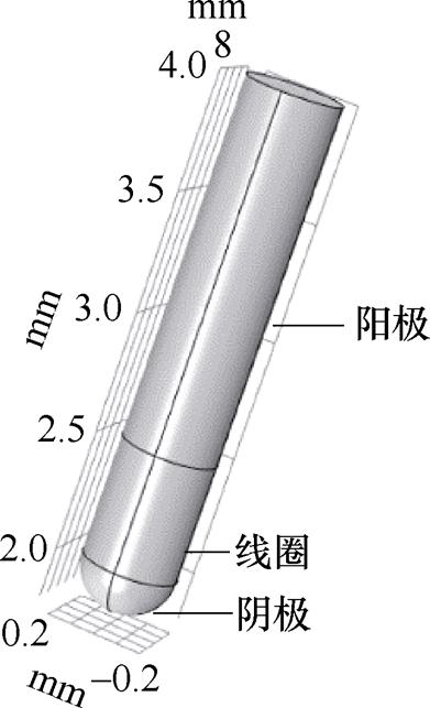
图2 心脏起搏器电极模型
Fig.2 Pacemaker electrode model
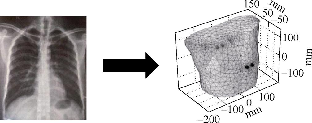
图3 人体胸腔三维剖分模型
Fig.3 3D mesh chest model of human
表1 肺呼吸状态的生理参数
Tab.1 Physiological parameters of lung respiratory state
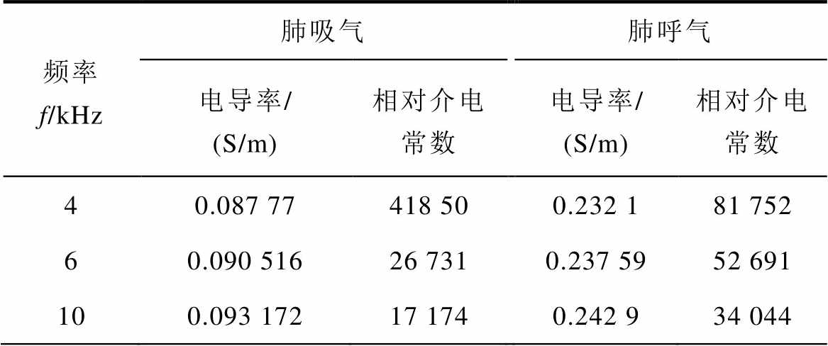
频率f/kHz肺吸气肺呼气 电导率/(S/m)相对介电常数电导率/(S/m)相对介电常数 40.087 77418 500.232 181 752 60.090 51626 7310.237 5952 691 100.093 17217 1740.242 934 044
(续)
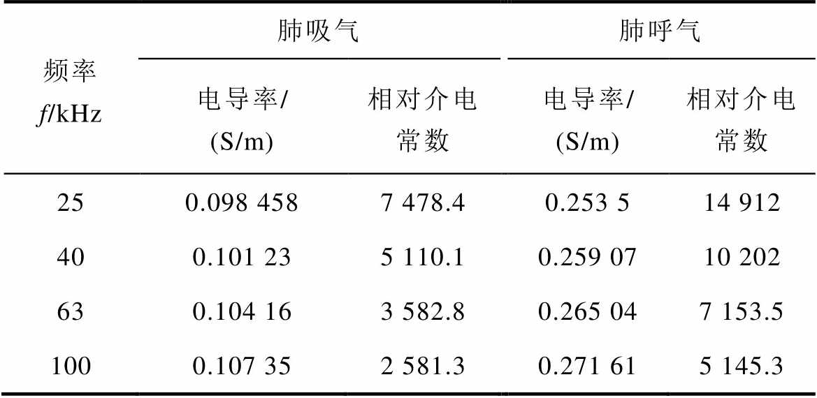
频率f/kHz肺吸气肺呼气 电导率/(S/m)相对介电常数电导率/(S/m)相对介电常数 250.098 4587 478.40.253 514 912 400.101 235 110.10.259 0710 202 630.104 163 582.80.265 047 153.5 1000.107 352 581.30.271 615 145.3
因为心脏起搏器电极相对于胸廓体积而言较小,在心脏起搏器电极周围添加正方体,代表求解的计算域,填充组织材料为肺脏,外加交变电流激励。外加交流激励对整个空间的影响如图4所示。
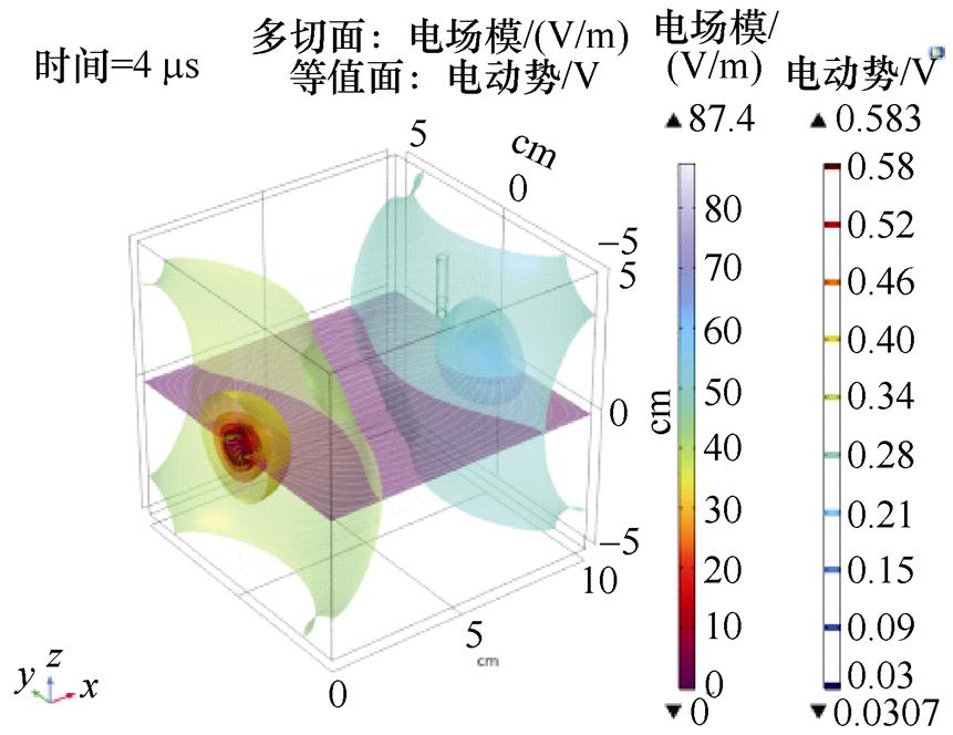
图4 交流激励对计算域影响
Fig.4 Influence of AC excitation on the domain
只对这个区域的场感兴趣,整个域内的电流沿着建模域从激励电极一端流向另一端,形成闭合电流流动。随着激励频率的增加,电流的趋肤效应越明显。以激励电极为中心,在域内形成电动势相等的若干个等势面。激励电极共两个,其中左侧的为激励端,右侧为接地端。左侧等势面电位要高于靠近右侧的等势面电位,心脏起搏器在空间域中靠左,其表面产生的感应电动势与左侧空间等势面保持一致。可见,通过外加交流的激励电流源,会在心脏起搏器电极产生感应电动势。
本文构建的是在三种不同电极位置下,激励频率分别为4、6、10、25、40、63和100 kHz的人体胸腔电阻抗检测系统仿真模型。通过施加5 mA的交流激励信号,计算佩戴心脏起搏器患者在不同条件下,心脏起搏器电极上的感应电动势。激励电极配置方式为第五肋骨附近,单层设置,为了得到对起搏电极最大影响的感应电动势,设定的激励电极与起搏器电极在同一层面,分别为相邻、相对、交叉的配置形式。激励电极配置方式如图5所示。相邻激励模式为通过1号电极与2号电极施加激励电流,相对激励模式为通过1号电极和4号电极施加激励电流,交叉激励模式为通过1号电极和3号电极施加激励电流。
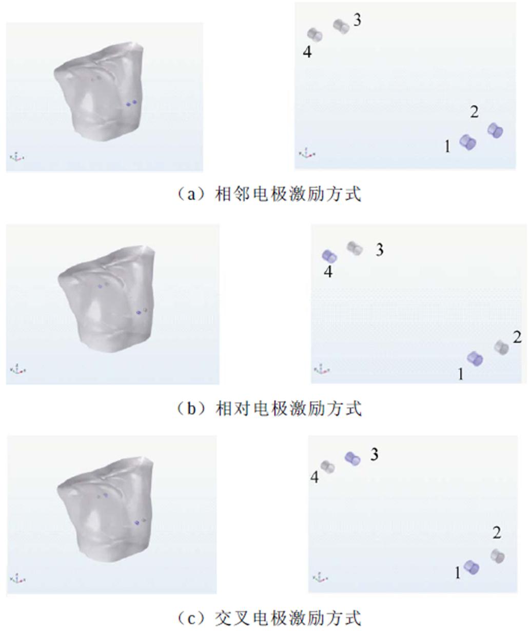
图5 激励电极配置方式
Fig.5 Excitation electrode configuration
表2为在电流激励下的有限元模型,其心脏起搏器电极的感应电动势。频率在4~100 kHz之间,由于组织在模拟频率范围内的电学特性,电干扰水平随频率不同而变化。突出显示的单元格对应于超过ISO 14117标准所允许的最大电压幅值。表2列出了模型因为激励电极位置和呼吸状态差异导致的干扰程度,显示呼气状态的感应电动势值比吸气状态的感应电动势值低。模型当中的组织特性取自同一个数据库,由于激励电极位置不同,干扰程度也有所不同。表2显示,在胸腔阻抗检测中,激励频率从4~100 kHz,在交叉激励配置条件下的干扰最高,相邻激励条件下的干扰最小。当激励频率至100 kHz时,干扰明显降低,且均未超过阈值最大电压幅度。整体来看,肺吸气状态下的干扰要高于肺呼气状态下的干扰,激励频率越高,感应电动势干扰越小。
表2 起搏电极上的感应电动势
Tab.2 The induced voltage on the pacemaker electrode
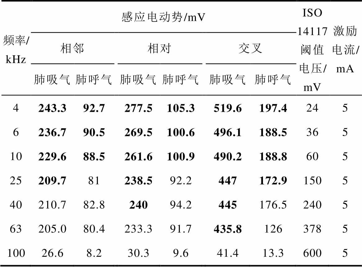
频率/kHz感应电动势/mVISO 14117阈值电压/mV激励电流/mA 相邻相对交叉 肺吸气肺呼气肺吸气肺呼气肺吸气肺呼气 4243.392.7277.5105.3519.6197.4245 6236.790.5269.5100.6496.1188.5365 10229.688.5261.6100.9490.2188.8605 25209.781238.592.2447172.91505 40210.782.824094.2445176.52405 63205.080.4233.391.7435.81263785 10026.68.230.39.641.413.36005
为验证外加交流激励信号对起搏器电极有影响,采用的实验装置如图6所示,它主要由模拟胸腔的塑料圆桶、交变恒流源、电压检测电路,以及模拟电阻棒、电极及导联线等组成。桶的内径为64 mm,内装满稀盐水,电阻棒尺寸为3 mm× 100 mm,材料为钛棒。激励电极采用相对的形式。电阻棒连接示波器探头,在示波器上显示输入激励后对电阻棒的干扰情况。为了与仿真实验保持一致,设定激励频率分别为4、6、10、25、40、63和100 kHz,激励电压为300 mV,实验结果如图7所示。
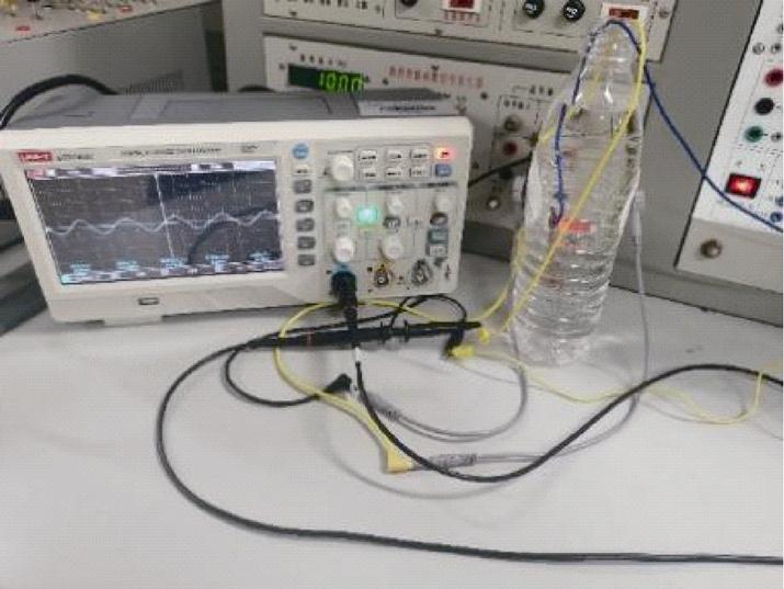
图6 电磁干扰实验
Fig.6 Experiment of electromagnetic interference
这里实际干扰表示实验条件下测得的电阻棒上的感应电动势,随着激励频率的增大,趋肤效应越明显,电阻棒上的感应电动势逐渐变小,其变化趋势与人体胸腔模型的仿真结果基本一致,说明采用阻抗法的激励电极会对组织内部产生干扰。
本研究评估了胸腔生物阻抗检测技术对心脏起搏器电极的影响,采用FDA认可的ISO 14117为标准。研究结果表明,由于组织和液体在模拟频率范围内的电特性,电干扰水平随着频率的变化而变化。总的来看,激励频率越低,干扰越强。电极在不同的位置时,干扰水平不同,交叉电极配置下的干扰最强,相邻电极配置下的干扰最弱,且有部分感应电动势超过ISO 14117设定的最大阈值电压。当佩戴心脏起搏器患者接受胸腔生物阻抗测量时,有可能由于干扰影响起搏器的正常工作,引起严重事件。由于存在潜在的电磁干扰,不建议利用胸阻抗法在心脏起搏器佩戴者身上进行检测。
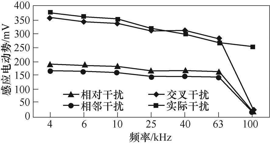
图7 频率与感应电动势的关系
Fig.7 The relationship between frequency and induced voltage
参考文献
[1] 《中国心血管健康与疾病报告2022》编写组. 《中国心血管健康与疾病报告2022》要点解读[J]. 中国心血管杂志, 2023, 28(4): 297-312.
The Writing Committee of the report on cardio- vascular health diseases in China. Interpretation of report on cardiovascular health and diseases in China 2022[J]. Chinese Journal of Cardiovascular Medicine, 2023, 28(4): 297-312.
[2] 章伟睿, 张涛, 史学涛, 等. 基于差分迭代的电阻抗成像算法研究[J]. 电工技术学报, 2021, 36(4): 747-755.
Zhang Weirui, Zhang Tao, Shi Xuetao, et al. An algorithm of electrical impedance tomography based on differential iteration[J]. Transactions of China Electrotechnical Society, 2021, 36(4): 747-755.
[3] Bera T K. Bioelectrical impedance methods for noninvasive health monitoring: a review[J]. Journal of Medical Engineering, 2014, DOI: 10.1155/2014/381251.
[4] Maciejewski D, Putowski Z, Czok M, et al. Electrical impedance tomography as a tool for monitoring mechanical ventilation: an introduction to the tech- nique[J]. Advances in Medical Sciences, 2021, 66(2): 388-395.
[5] Naranjo-Hernández D, Reina-Tosina J, Min M. Fundamentals, recent advances, and future challenges in bioimpedance devices for healthcare applica- tions[J]. Journal of Sensors, 2019, 2019(3): 1-42.
[6] Wang Qi, Wang Jianming, Li Xiuyan, et al. Exploring respiratory motion tracking through electrical impedance tomography[J]. IEEE Transactions on Instrumentation and Measurement, 2021, 70: 1-12.
[7] Zouari F, Oon W Y, Modak D, et al. Affordable, portable and self-administrable electrical impedance tomography enables global and regional lung function assessment[J]. Scientific Reports, 2022, 12: 20613.
[8] Nikishov A, Pavlov K, Chang N, et al. Bio-electrical impedance analysis for wrist-wearable devices[C]// 2022 IEEE-EMBS International Conference on Biomedical and Health Informatics (BHI), Ioannina, Greece, 2022: 1-6.
[9] Joeal S. Multi-frequency segmental bio-impedance device: design, development and applications[D]. Birmingham, West Midlands, UK: Aston University, 2014.
[10] Malbrain M L N G, Huygh J, Dabrowski W, et al. The use of bio-electrical impedance analysis (BIA) to guide fluid management, resuscitation and deresusci- tation in critically ill patients: a bench-to-bedside review[J]. Anaesthesiology Intensive Therapy, 2014, 46(5): 381-391.
[11] Roehrich L, Suendermann S, Just I A, et al. Safety of bioelectrical impedance analysis in advanced heart failure patients[J]. Pacing and Clinical Electro- physiology: PACE, 2020, 43(10): 1078-1085.
[12] Garlini L M, Alves F D, Kochi A, et al. Safety and results of bioelectrical impedance analysis in patients with cardiac implantable electronic devices[J]. Brazilian Journal of Cardiovascular Surgery, 2020, 35(2): 169-174.
[13] Khalil S F, Mohktar M S, Ibrahim F. The theory and fundamentals of bioimpedance analysis in clinical status monitoring and diagnosis of diseases[J]. Sensors, 2014, 14(6): 10895-10928.
[14] Chabin X, Taghli-Lamallem O, Mulliez A, et al. Bioimpedance analysis is safe in patients with implanted cardiac electronic devices[J]. Clinical Nutrition, 2019, 38(2): 806-811.
[15] Ha G B, Steinberg B A, Freedman R, et al. Safety evaluation of smart scales, smart watches, and smart rings with bioimpedance technology shows evidence of potential interference in cardiac implantable electronic devices[J]. Heart Rhythm, 2023, 20(4): 561-571.
[16] 杨威, 徐英雷, 王晨曲, 等. 无线传能机车人体电磁环境安全研究[J]. 电工技术学报, 2022, 37(11): 2665-2672.
Yang Wei, Xu Yinglei, Wang Chenqu, et al. An electromagnetic safety study about human body in electric locomotive wireless charging system[J]. Transactions of China Electrotechnical Society, 2022, 37(11): 2665-2672.
[17] 于宙, 肖文勋, 张波, 等. 电场耦合式无线电能传输技术的发展现状[J]. 电工技术学报, 2022, 37(5): 1051-1069.
Yu Zhou, Xiao Wenxun, Zhang Bo, et al. Deve- lopment status of electric-field coupled wireless power transmission technology[J]. Transactions of China Electrotechnical Society, 2022, 37(5): 1051-1069.
[18] 沈栋, 杜贵平, 丘东元, 等. 无线电能传输系统电磁兼容研究现况及发展趋势[J]. 电工技术学报, 2020, 35(13): 2855-2869.
Shen Dong, Du Guiping, Qiu Dongyuan, et al. Research status and development trend of electro- magnetic compatibility of wireless power trans- mission system[J]. Transactions of China Electro- technical Society, 2020, 35(13): 2855-2869.
[19] 雷银照. 关于电磁场解析方法的一些认识[J]. 电工技术学报, 2016, 31(19): 11-25.
Lei Yinzhao. Reviews of analytical methods for electromagnetic fields[J]. Transactions of China Electrotechnical Society, 2016, 31(19): 11-25.
[20] 胡健伟, 汤怀民[编]. 微分方程数值方法[M]. 2版. 北京: 科学出版社, 2007.
[21] ANSI/AAMI/ISO 14117. Active implantable medical devices-Electromagnetic compatibility-EMC test protocols for implantable cardiac pacemakers, implantable cardioverter defibrillators and cardiac resynchronization devices[S]. 2019. https://www.iso. org/standard/73915.html. Accessed December 21, 2022.
[22] 赵军, 赵毅航, 武志军, 等. 电动汽车无线充电系统对心脏起搏器的电磁兼容与热效应影响[J]. 电工技术学报, 2022, 37(增刊1): 1-10.
Zhao Jun, Zhao Yihang, Wu Zhijun, et al. The influence of electric vehicle wireless charging system on electromagnetic compatibility and thermal effect of cardiac pacemaker[J]. Transactions of China Electrotechnical Society, 2022, 37(S1): 1-10.
[23] Gabriel C, Gabriel S, Corthout E. The dielectric properties of biological tissues: I. literature survey[J]. Physics in Medicine and Biology, 1996, 41(11): 2231-2249.
[24] Gabriel S, Lau R W, Gabriel C. The dielectric properties of biological tissues: II. measurements in the frequency range 10 Hz to 20 GHz[J]. Physics in Medicine and Biology, 1996, 41(11): 2251-2269.
[25] Gabriel S, Lau R W, Gabriel C. The dielectric properties of biological tissues: III. parametric models for the dielectric spectrum of tissues[J]. Physics in Medicine and Biology, 1996, 41(11): 2271-2293.
Safety Evaluation of Thoracic Bio-Electrical Impedance Technique
Abstract Due to the increasingly serious aging society and environmental factors, the incidence of cardiovascular diseases is increasing year by year. According to data from the 25th National Forum on Interventional Cardiology, the number of pacemaker implants in China reached 99 000 units, a year-over-year increase of 15.1% in 2021. Cardiac implantable electronic devices contain multiple microcircuits, easily affected by medical devices such as magnetic resonance imaging, electrosurgery, and bio-electrical impedance. With the development and application of bio-electrical impedance technology, attention should be paid to electromagnetic interference.
The alternating high-frequency signal is the core part of the bioelectrical impedance excitation system. When an alternating current is applied to the electrode, an alternating electric field is generated between the two electrodes, filling the entire space. Current is constrained by external excitation and space of electromagnetic field.
Firstly, a 3D simulation model based on a simplified pacemaker electrode model and real thoracic. Secondly, the dielectric properties of biological tissue are set according to the website of dielectric properties of human tissues and organs. Thirdly, inject 5 mA current excitation at 4, 6, 10, 25, 40, 63, and 100 kHz. The excitation electrode is arranged near the 5th frame. To obtain the induced voltage that has the greatest influence on the pacemaker electrode, the excitation electrode and the pacemaker electrode are set at the same level, and the configuration form is adjacent, opposite, and cross, respectively. In this way, the induced voltage values of the pacemaker electrode under different excitations are obtained.
Simulation results show that the level of electrical interference varies with frequency between 4 kHz and 100 kHz. The induced voltage of the expiratory state is lower than that of the inspiratory state. The tissue characteristics in the model are taken from the same database, and the interference degree is different due to the location of the excitation electrode. The interference of cross-excitation configuration is the highest, and the interference of adjacent excitation is the least. When the excitation frequency is 100 kHz, the interference is significantly reduced, and the data does not exceed the maximum voltage amplitude threshold. Overall, the interference in the inhaling state of the lung is higher than that in the exhaling state of the lung. The higher the excitation frequency, the smaller the induced voltage interference. A plastic circular cavity with salt water is used to simulate the chest cavity and tissue, and the titanium rod is in the salt water. The interference of input excitation to the resistance rod can be observed on the oscilloscope. It is found that the induced voltage on the resistance rod decreases gradually with the increase of frequency by changing the injected electrode. The changing trend is consistent with the human chest cavity model.
The following conclusions can be drawn from the simulation analysis: (1) The level of electrical interference varies with frequency. The lower the excitation frequency, the stronger the interference. (2) The interference level of electrodes is different in different positions. The interference is strongest in cross-electrode configuration and weakest in adjacent. (3) Some induced voltages exceed the maximum threshold voltage specified in ISO 14117.
Potential electromagnetic interference exists in patients with cardiac pacemakers. Since interference may affect the pacemaker’s normal operation and cause serious events, the thoracic bio-impedance method is not recommended for testing on pacemaker wearers.
Keywords:Pacemaker, thoracic electrical impedance, induced voltage, device interference
中图分类号:TM15
DOI: 10.19595/j.cnki.1000-6753.tces.231733
国家自然科学基金资助项目(52077143)。
收稿日期 2023-10-18
改稿日期 2023-12-04
贾 静 女,1988年生,博士研究生,讲师,研究方向为生物电磁成像与智能医疗。
E-mail: jj_10066@163.com
柯 丽 女,1977年生,教授,博士生导师,研究方向为生物电磁成像与智能医疗。
E-mail: keli@sut.edu.cn(通信作者)
(编辑 陈 诚)