
图1 非隔离型单相三桥臂UPQC拓扑结构与等效电路
Fig.1 Single-phase transformerless three-leg UPQC topology structure and equivalent circuit
摘要 非隔离型单相三桥臂统一电能质量控制器(UPQC)可以实现交流电压调节和并网点无功治理等功能,但传统控制方法直流侧母线电压高、二倍频波动大,既给设备带来巨大的电容成本,又影响设备的安全可靠运行。为了解决这些问题,该文详细分析了不同工况下直流侧电压的约束范围,推导了直流电压波动随并网点和负载功率因数、串联电压补偿相位、参考直流电压等复杂因素的关联性,并提出一种直流电压灵活降低与主动波动抑制控制方法。相比于传统控制,应用所提方法母线电压可降低至相电压峰值附近,二倍频电压波动可降低约80%。最后,实验验证了所提三桥臂UPQC直流电压控制技术的正确性。
关键词:单相三桥臂统一电能质量控制器 直流电压波动 直流电压控制 主动波动抑制
近年来,随着分布式可再生能源发电的快速发展,各式冲击性、非线性负载大规模接入配电网,电能质量问题受到了广泛关注[1-5]。统一电能质量控制器(Unified Power Quality Controller, UPQC)以其综合补偿能力,成为未来配电网电能质量治理设备的理想选择[6-8],其中无隔离变压器型结构体积小、质量轻、经济成本低,在实际应用中更具优势[9-10]。对于单相UPQC,按照拓扑结构可以划分为全桥结构、三桥臂结构和半桥结构。三桥臂结构是在全桥的基础上,复用一对桥臂,既不影响输出波形质量,又达到减少开关器件使用数量的目的,并且通过特定的调制策略,实现复用桥臂的解耦[11-12]。然而非隔离型单相三桥臂UPQC,因其拓扑结构的特殊性,对直流侧电压提出了更高的要求。此外,串联端口和并联端口瞬时功率不平衡,造成直流母线电压的严重波动,影响设备的正常运行[13]。
现有研究中,电力电子设备直流侧参考电压往往设定为一个较高的固定值,这样一方面要求直流母线电容具有较高的耐压值,增加了设备成本,另一方面还会产生较大的开关损耗,降低设备的运行效率[14-15]。为降低直流侧电压,文献[16]从调制的角度,给出了直流侧电压参考下限,即不低于线电压的峰值;更进一步,文献[17]提出在电网电压变化时,根据调制所需最低电压,实时改变直流侧电压参考。但是这些方法均没有考虑直流侧电压波动,尤其是当下对经济性的追求,电力电子设备直流母线电容容量设计较小,直流侧电压波动尤为严重。近年来,关于多端口电力电子设备直流侧电压波动的治理,国内外学者进行了大量的研究。这些方法主要分为两类:第一类是通过在直流母线上增设辅助装置,主动地维持母线电压稳定,这种方法理论上可以完全抑制直流母线上的电压波动,但是会为设备增加额外的成本[18-19];第二类是同步控制方法[20],控制各个端口输出的瞬时功率达到完全平衡,从源头上消除直流母线电压波动,然而对于隔离型单相三桥臂UPQC来说,串联端口和并联端口的瞬时功率往往不能实现完全平衡。
本文基于非隔离型单相三桥臂UPQC,分析了不同工况下直流母线电压的约束范围,建立了直流母线电压二倍频波动模型。基于所建立的模型,研究了不同运行工况对直流电压需求和波动大小的影响,并提出了一种自适应直流母线电压调整方案,根据母线电压波动量和静态基准自适应调节直流母线电压参考,使直流侧电压满足其调制需求,保证设备正常运行。此外,通过调整负载电压移相角和电网无功补偿系数,来降低直流母线上的电压波动。最后,通过实验验证了所提方法的可行性,并与传统方法进行对比,体现了所提方法在降低直流母线电压波动上的优越性。
非隔离型单相三桥臂UPQC的拓扑结构与等效电路如图1所示。并联端口部分由桥臂a(VT1, VT2)、桥臂b(VT3, VT4)、以及端口滤波器(La1, La2, Ca)组成,该部分与电网并联,来补偿电网侧功率因数和谐波电流,以及支撑直流母线电压vdc。串联端口部分由桥臂b(VT3, VT4),桥臂c(VT5, VT6)和串联滤波器(Cbc, Lc)组成,该部分串联在电网与负载之间,用以补偿负载电压vL。不难看出,桥臂b(VT3, VT4)为复用桥臂,利用文献[11]所提的调制方法,可以实现复用桥臂的解耦。

图1 非隔离型单相三桥臂UPQC拓扑结构与等效电路
Fig.1 Single-phase transformerless three-leg UPQC topology structure and equivalent circuit
根据串、并联端口的不同作用,并联端口可以等效为一个电流源,并联在电网上;串联端口可以等效为一个电压源,串联在电网与负载之间。串、并联端口之间,经过直流母线电容进行有功功率交换,如图1所示。图中,ppc表示并联端口流向直流母线电容的瞬时功率,psc表示直流母线电容流向串联端口的瞬时功率。鉴于滤波器上的压降过小,故本文简化模型中忽略滤波器,因此等效电流源两端电压vg即可等效为两桥臂中点b、a间电压vba,等效电压源两端电压vsc即可等效为两桥臂中点c、b间电压vcb,而负载电压vL即可等效为两桥臂中点c、a间电压vca。
为了方便看出补偿系统中的电压、电流的相位关系,忽略谐波因素,将图1等效电路中的电气量用相量表示,如图2所示,图中, 、
、 、
、 分别为电网电压相量、负载电压相量和补偿电压相量。
 、
、 、
、 分别为电网电流相量、负载电流相量以及补偿电流相量。为了清楚地显示并联变换器与串联变换器提供的有功分量和无功分量,补偿电压相量
 被分解为有功部分
 与无功部分
与无功部分 。补偿电流相量
 被分解为有功部分
 和无功部分
和无功部分 。另外,jL、d、jg分别表示负载功率因数角、负载电压移相角和电网侧功率因数角。从相量图可以看出,在电压补偿方面,UPQC的控制目标在于将负载侧电压标幺值补偿至1.0(pu),负载电压移相角
 根据不同工况进行自由选择;在电流补偿方面,UPQC的控制目标在于将网侧功率因数补偿到规定范围,其中,在功率因数满足要求的前提下,补偿系数k可以自由选择。综上所述,不难看出,在UPQC的控制层面上,拥有两个控制自由度,分别是负载电压移相角
 和无功功率补偿系数k。
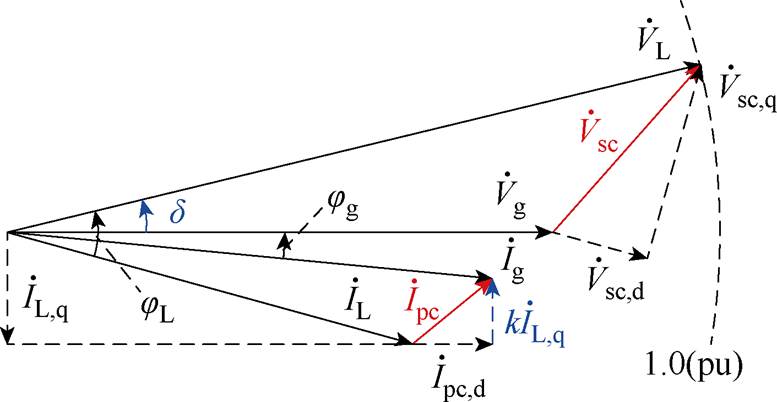
图2 补偿系统电压、电流相量
Fig.2 Voltage and current vectors for the compensation system
针对非隔离型单相三桥臂UPQC的拓扑结构,为了不出现过调制现象,其直流母线电压vdc需要大于每个交流端口的输出电压。在不考虑滤波器压降的情况下,即满足约束条件
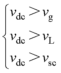 (1)
(1)
忽略谐波因素,直流母线理论最低电压 为
为
 (2)
(2)
式中,Vsc为补偿电压有效值。为了确定 的具体数值,需要对Vg、VL、Vsc的大小进行划分。根据三个电压最大值的不同选择,可以划分为四种情况,如图3所示。

图3 判断max(Vg, VL, Vsc)取值的四种情况
Fig.3 Four different situations for judging max(Vg, VL, Vsc)
第一种情况,当Vg<1.0(pu), <arccos(Vg/2)时,VL最大,此时,
 取值为
取值为
 (pu) (3)
第二种情况,当Vg<1.0(pu), >arccos(Vg/2)时,Vsc最大,此时,
 取值为
取值为
 (4)
(4)
第三种情况,当Vg>1.0(pu), <arccos[1/(2Vg)]时,Vg最大,此时,
 取值为
取值为
 (5)
(5)
第四种情况,当Vg>1.0(pu), >arccos[1/(2Vg)]时,Vsc最大,此时,
 取值依然为式(4)。
根据每种情况下 的表达式,得到不同电网电压Vg、不同负载移相角
 下,
下, 的分布图,如图4所示。为了表示方便,
 按照额定电网电压标幺化表示。从图4中可以看出,前文所分析的四种不同情况下,
 的分布状态呈现出明显的不同,这从结果上验证了前文分析的合理性。
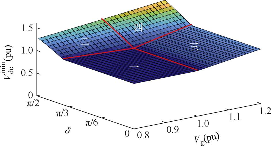
图4 不同电网电压Vg和负载电压移相角 下,
下, 分布
分布
Fig.4 Distribution diagram of  under different Vg and
非隔离型单相三桥臂UPQC直流母线上的电压波动,是由于其串联端口输入瞬时功率psc与并联端口输出功率ppc不平衡导致的。为了研究这一现象,本文从功率守恒的角度,对直流母线电压波动进行定量化建模。利用图2中电压、电流相量的幅值相位关系,得到并联端口输入瞬时功率ppc为
 (6)
(6)
串联端口输出瞬时功率psc为
 (7)
(7)
联合式(6)和式(7),再根据电网输出功率与负载消耗功率相等的关系,得到流入直流母线的瞬时功率pdc为
 (8)
(8)
式中, 为功率波动初相位;A为功率波动幅值,A的表达式为
 (9)
(9)
式中,S为负载容量。
再根据电容电压与功率的关系,得到直流母线二倍频纹波电压幅值 为
为
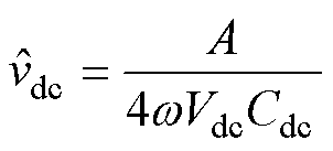 (10)
(10)
从数学表达式可以看出, 与直流母线电压Vdc,直流母线电容Cdc等因素成反比,与负载容量S成正比。但是与负载电压移相角
 、电网侧功率因数角jg、负载功率因数角jL的关系不明显。然而,由图2中的相量图看出,补偿系统中的两个控制自由度恰与这些量有关联。因此,为了弄清楚如何利用控制手段降低直流母线上的电压波动,探究
 、jL和jg对
 的影响很有必要。通过数学手段,对A求关于
 的偏导,得到在仅考虑负载电压移相角
 的情况下,当
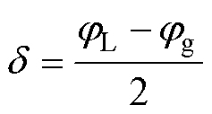 (11)
(11)
时, 最小。进一步分析可得,在当
 满足式(11)时,补偿后电网侧功率因数角jg越接近负载功率因数角jL,直流母线电压波动幅值越小,特别地,当jg=jL时,理论上
 =0。
=0。
取负载容量为30 kW,负载功率因数为0.8,直流母线电容为2 500 mF,直流母线电压为400 V。此时,根据式(9)和式(10),得到直流母线电压波动幅值 与负载电压移相角
 以及补偿后电网侧功率因数cosjg之间的关系,如图5所示。
从图5中可以得到两个结论:①不论补偿后电网侧功率因数为多少, 总是在一定值时取得最小;②当cosjg越趋近cosjL,
 极值越小,而当cosjg=cosjL=0.8时,
 最小值取0。以上两个结论进一步验证了前文分析的合理性。
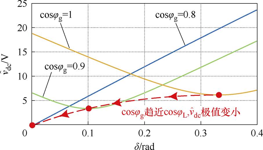
图5 不同d 和cosjg下 变化
变化
Fig.5 DC link ripple voltage during the different cosjg and d
通过第2节的分析可知,对负载电压移相角 、无功补偿系数k进行合理控制,可以降低直流母线电压波动幅值
 ,综合考虑
,综合考虑 、Vg以及
、Vg以及 ,可以得到直流母线理论最低电压。下面依次介绍
 、k以及直流母线电压参考设定值
 的控制方案。
 的控制
的控制根据式(11)的结论,直接计算出 的具体数值并进行给定。其中jL、jg分别根据电压、电流瞬时值vL、iL和vg、ig进行计算。此外,为了防止因为移相角的跳变而引起的负载电力电子设备换相失败等问题[21],在
 的给定之前增加变化率限制,从而保证在计算出的
 发生跃变时,
 给定的参考通过斜坡的方式平稳地过渡,从而避免负载电压相位发生跃变。此部分的控制框图如图6所示。
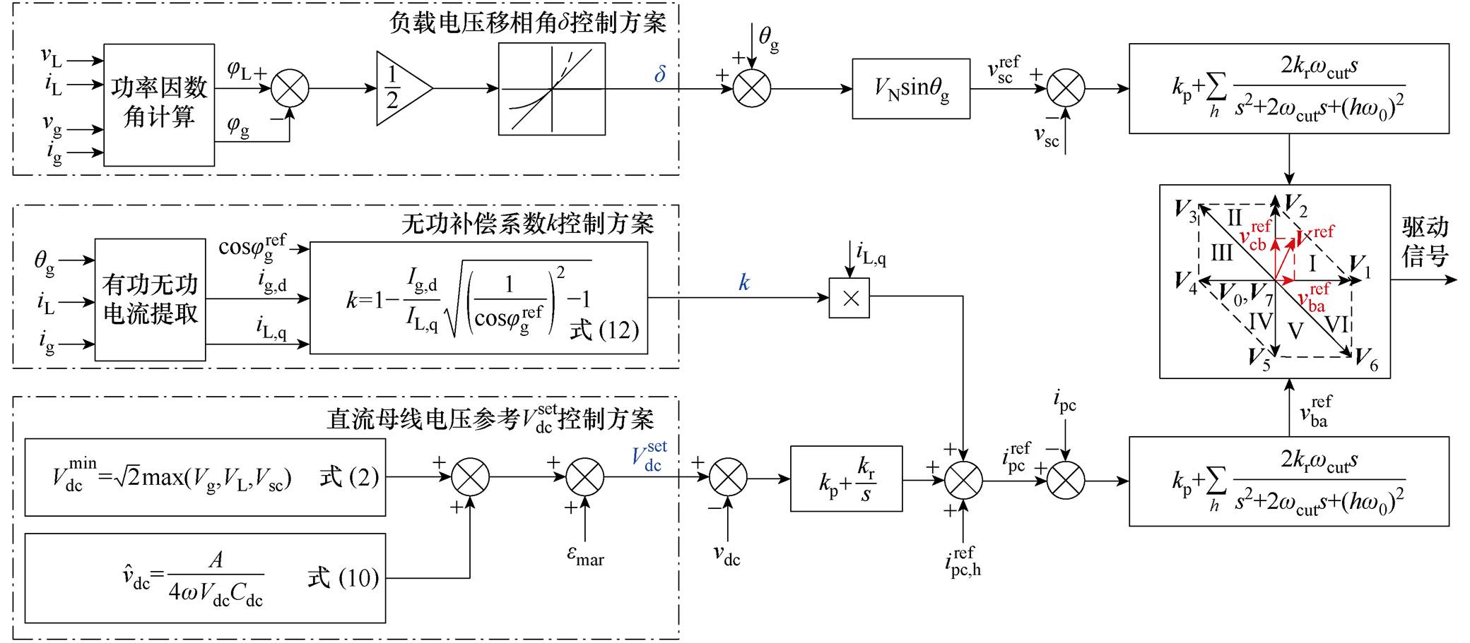
图6 本文所提策略控制框图
Fig.6 Diagram of proposed control system
无功补偿系数k决定着设备的并联补偿端口对于负载无功的补偿程度,该系数的选择既要保证电网侧功率因数满足可能存在的限制条件,又要使得直流母线电压波动尽可能小。根据第2.2节的分析可知,补偿后电网侧功率因数cosjg越趋近于负载功率因数cosjL,直流母线电压波动幅值 越小。因此,在实际工况能够满足电网侧功率因数等于负载功率因数时,则调整补偿系数k,使得cosjg= cosjL,而在实际工况不能够满足电网侧功率因数等于负载功率因数时,则调整补偿系数k,使得cosjg为限制值。关于k值的确定,参照图2,计算公式为
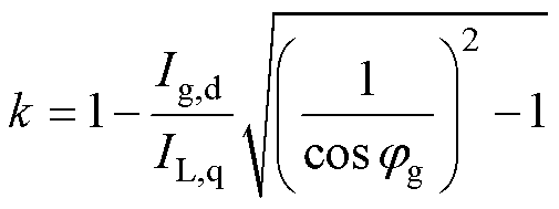 (12)
(12)
补偿系数k给定的具体控制框图,如图6所示。
 的给定
的给定给非隔离型单相三桥臂UPQC设定过高的直流母线电压,会给设备带来较低的直流母线电压利用率。而降低直流母线电压,则可以提高电压利用率。根据直流母线理论最低电压模型,在仅考虑基波电压调制需求的情况下,直流母线理论最低电压 由式(3)~式(5)确定;根据直流母线电压波动模型,直流母线电压波动幅值
 由式(10)确定。综上所述,在考虑直流母线电压波动、谐波因素以及滤波器压降的条件下,非隔离型单相三桥臂UPQC设备最低直流母线电压参考
 设定为
设定为
 (13)
(13)
式中, 为常数,表示谐波和滤波器压降等其他因素所留的裕量。此时,
 表示在综合考虑所有条件下,非隔离型单相三桥臂UPQC设备的最低直流母线电压设定。
由于 与
与 均与负载电压移相角
 有关,因此,关于最小化直流母线电压设定与最小化直流母线电压波动的目标就会有耦合关系。但是,对直流母线理论最低电压模型进一步研究发现,当
 <p/3时,
 与
与 无关;只有
无关;只有 >p/3时,
 才与
才与 有关。而根据直流母线电压波动模型,即使负载功率因数为0,
 在取p/4时,直流母线电压波动值
 取得最小,并且随着负载功率因数的变大,
 取最小时所对应的
 变小。因此,综上分析,在实际应用中,
 与
与 关于
关于 解耦。
解耦。
关于直流母线电压参考值 设定的计算,具体细节过程亦如图6所示。
本文给出了基于非隔离型单相三桥臂UPQC原型机进行实验的结果,实验平台如图7所示,相关实验参数见表1。
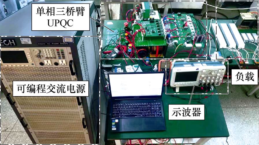
图7 实验平台
Fig.7 Experiment platform
表1 实验参数
Tab.1 Experimental parameters

参 数数 值 额定电网电压(有效值)VN/V44 直流母线电容Cdc/mF500 开关频率fsw/kHz10 并联端口滤波器La1/mH0.4 La2/mH0.1 Ca/mF60 串联端口滤波器Lc/mH0.4 Cbc/mF60
电网欠电压补偿实验结果如图8所示。电网电压从1.0(pu)突然降低到0.8(pu),实验结果表明,负载电压几乎没有变化,满足控制要求。尽管电网电压跳变至0.8(pu),但是根据式(13)可知,直流侧电压参考没有发生变化,实验中直流母线电压始终维持在94 V,与所提出的控制策略相符。
电网过电压补偿实验结果如图9所示。电网电压从1.0(pu)突然升高到1.2(pu),实验结果表明,负载电压几乎没有变化,满足控制要求。由于电网电压的升高,根据式(13),直流母线电压参考随之改变,因此实验中直流母线电压由95 V升高到106 V,与所提出的控制策略相符。

图8 电网欠电压补偿实验结果
Fig.8 Experimental results of grid undervoltage compensation

图9 电网过电压补偿实验结果
Fig.9 Experimental results of grid overvoltage compensation
负载跳变实验结果如图10所示。跳变前,负载视在功率为387 V×A,负载功率因数为0.8;跳变后,负载视在功率为484 V×A,负载功率因数为1.0。实验结果表明,当负载功率因数跳变时,电网侧功率因数始终为1,满足控制目标。

图10 负载功率因数跳变实验结果
Fig.10 Experimental results of load power factor jump
最后,进行电网侧功率因数参考跳变实验,实验结果如图11所示,电网功率因数参考从1.0跳变至0.85。实验结果表明,当电网功率因数参考跳变时,实际测得的电网功率因数可以实现跟踪,满足控制目标。
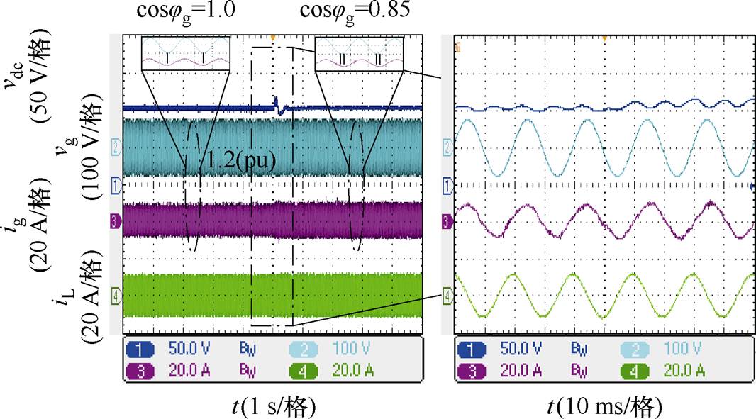
图11 电网功率因数参考跳变实验结果
Fig.11 Experimental results of grid power factor reference jump
对比验证实验一共分为四个阶段,每个阶段的相关参数设置见表2,实验结果如图12所示。
表2 实验相关参数
Tab.2 Parameters of the comparative experiment

阶段电网电压(pu)负载功率电网功率因数参考电压补偿策略 PL/WQL/var 阶段11.23302501.0传统方法 阶段21.23302501.0所提方法 阶段31.23302500.9所提方法 阶段41.2330250cosjg所提方法
可以看出,与传统的同相位负载电压补偿方法相比,本文所提出的补偿策略在直流母线电压抑制上具有显著效果,所提方法在电网侧功率因数要求为1时,直流母线电压波动幅值为传统方法的50%;当电网侧功率因数要求不低于0.9时,直流母线电压波动幅值为传统方法的35%;当电网侧功率因数没有要求时,直流母线电压波动幅值仅为传统方法的20%,满足理论上的预期效果。

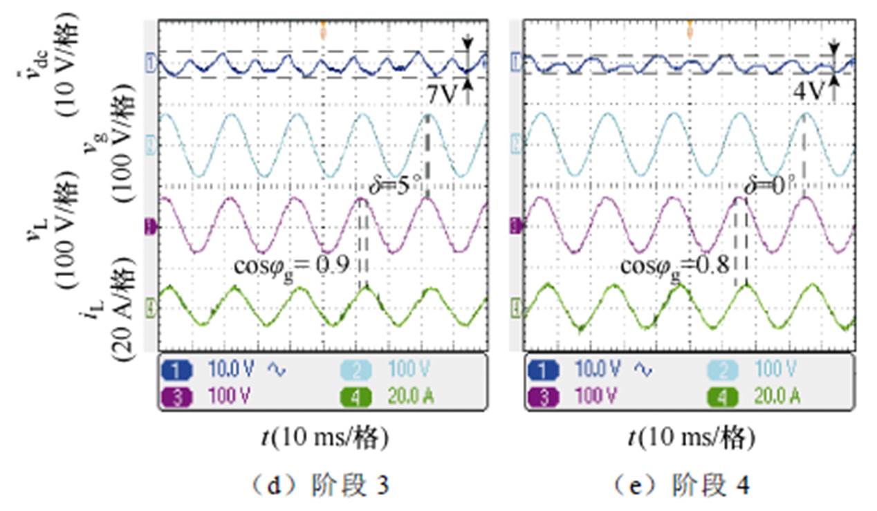
图12 不同控制方法直流母线电压波动对比实验
Fig.12 Comparison experiment of DC bus voltage fluctuation with different control methods
为了降低非隔离型单相三桥臂UPQC直流侧电容成本,提高设备安全运行裕度,本文通过理论分析与实验验证,提出了一种直流电压灵活降低与主动波动抑制控制方法,并得出结论如下:
1)直流侧母线电压的设定应充分考虑电网电压、补偿电压、补偿后负载电压以及直流侧电压波动等因素的大小。本文所提出的一种直流侧电压灵活调节方案,可以将母线电压降低至相电压峰值附近,此举极大地降低了直流侧电压大小,达到实现缩减直流母线电容成本的目的。
2)直流母线电压波动受负载容量,负载功率因数以及电网侧功率因数的影响,还受补偿后负载电压移相角的影响。本文所提出的通过调整补偿后负载电压移相角以及无功补偿系数来降低直流母线电压波动的方法,可以显著地降低直流母线上的电压波动,保障设备安全稳定运行。
本文所提方法仅是在考虑基波条件下,对非隔离型单相三桥臂UPQC直流侧电压的控制方案,对谐波条件下关于直流侧电压的控制将在后续工作中进一步研究。
参考文献
[1] 张勇军, 羿应棋, 李立浧, 等. 双碳目标驱动的新型低压配电系统技术展望[J]. 电力系统自动化, 2022, 46(22): 1-12.
Zhang Yongjun, Yi Yingqi, Li Licheng, et al. Prospect of new low-voltage distribution system technology driven by carbon emission peak and carbon neutrality targets[J]. Automation of Electric Power Systems, 2022, 46(22): 1-12.
[2] Nejabatkhah F, Li Yun wei, Sun Kai, et al. Active power oscillation cancelation with peak current sharing in parallel interfacing converters under unbalanced voltage[J]. IEEE Transactions on Power Electronics, 2018, 33(12): 10200-10214.
[3] 何晋伟, 孟维奇, 蒋玮, 等. 新能源配电网电能质量典型问题分析及应对策略[J]. 高电压技术, 2023, 49(7): 2983-2994.
He Jinwei, Meng Weiqi, Jiang Wei, et al. Power quality problems in renewable energy power distribution systems: analysis and solutions[J]. High Voltage Engineering, 2023, 49(7): 2983-2994.
[4] 邵振国, 林洪洲, 陈飞雄, 等. 采用区间动态状态估计的局部不可观系统谐波源定位[J]. 电工技术学报, 2023, 38(9): 2391-2402.
Shao Zhenguo, Lin Hongzhou, Chen Feixiong, et al. Harmonic source location in the partial unobservable system based on interval dynamic state estimation[J]. Transactions of China Electrotechnical Society, 2023, 38(9): 2391-2402.
[5] 郑军铭, 冯丽, 蔡志远, 等. 提高短时中断故障期间新能源微电网稳定性的惯性储能永磁发电机组[J]. 电工技术学报, 2022, 37(23): 6000-6010.
Zheng Junming, Feng Li, Cai Zhiyuan, et al. The inertia motivity permanent magnet machine set for improving the stability of new energy microgrid during short-term interruption[J]. Transactions of China Electrotechnical Society, 2022, 37(23): 6000- 6010.
[6] 倪福银, 李正明. 统一电能质量调节器的研究发展综述[J]. 电力系统保护与控制, 2020, 48(20): 177- 187.
Ni Fuyin, Li Zhengming. Overview of unified power quality conditioner research development[J]. Power System Protection and Control, 2020, 48(20): 177- 187.
[7] da Silva S A O, Campanhol L B G, Pelz G M, et al. Comparative performance analysis involving a three- phase UPQC operating with conventional and dual/ inverted power-line conditioning strategies[J]. IEEE Transactions on Power Electronics, 2020, 35(11): 11652-11665.
[8] 张明, 王松峰. 中压配电系统的电能质量治理研究[J]. 电气技术, 2020, 21(9): 103-107.
Zhang Ming, Wang Songfeng. Study on power quality control of mid-voltage distribution system[J]. Elec- trical Engineering, 2020, 21(9): 103-107.
[9] Kumar C, Mishra M K. Predictive voltage control of transformerless dynamic voltage restorer[J]. IEEE Transactions on Industrial Electronics, 2015, 62(5): 2693-2697.
[10] 张洪亮, 张子成, 陈杰, 等. 自适应三次谐波注入的回接型LCL光伏逆变器共模谐振电流抑制方法[J]. 电工技术学报, 2023, 38(1): 220-233.
Zhang Hongliang, Zhang Zicheng, Chen Jie, et al. Common-mode resonant current suppression for back-connected LCL photovoltaic inverter using adaptive third harmonic injection[J]. Transactions of China Electrotechnical Society, 2023, 38(1): 220-233.
[11] de Sousa R P R, de Moraes Lima Marinus N S, Jacobina C B, et al. A unidirectional single-phase AC-DC-AC three-level three-leg converter[J]. IEEE Transactions on Industry Applications, 2019, 55(2): 1708-1716.
[12] Lu Yong, Xiao Guochun, Wang Xiongfei, et al. Control strategy for single-phase transformerless three-leg unified power quality conditioner based on space vector modulation[J]. IEEE Transactions on Power Electronics, 2016, 31(4): 2840-2849.
[13] Meng Linghui, Ma Lan, Zhu Weiwei, et al. Control strategy of single-phase UPQC for suppressing the influences of low-frequency DC-link voltage ripple[J]. IEEE Transactions on Power Electronics, 2022, 37(2): 2113-2124.
[14] Qin Shibin, Lei Yutian, Barth C, et al. A high power density series-stacked energy buffer for power pulsation decoupling in single-phase converters[J]. IEEE Transactions on Power Electronics, 2017, 32(6): 4905-4924.
[15] 姚绪梁, 罗兴鸿, 马赫, 等. 小电容双PWM调速系统直流母线电压波动抑制策略[J]. 电工技术学报, 2022, 37(12): 2971-2981.
Yao Xuliang, Luo Xinghong, Ma He, et al. DC bus voltage fluctuation suppression strategy for small capacitance dual-PWM speed regulating system[J]. Transactions of China Electrotechnical Society, 2022, 37(12): 2971-2981.
[16] Zhao Guopeng, Liu Jinjun, Yang Xin, et al. Analysis and specification of DC side voltage in parallel active power filter regarding compensation characteristics of generators[C]//2008 IEEE Power Electronics Specialists Conference, Rhodes, Greece, 2008: 3495-3499.
[17] 谢斌, 戴珂, 张树全, 等. 并联型有源电力滤波器直流侧电压优化控制[J]. 中国电机工程学报, 2011, 31(9): 23-29.
Xie Bin, Dai Ke, Zhang Shuquan, et al. Optimization control of DC link voltage for shunt active power filter[J]. Proceedings of the CSEE, 2011, 31(9): 23-29.
[18] Mellincovsky M, Yuhimenko V, Peretz M M, et al. Low-frequency DC-link ripple elimination in power converters with reduced capacitance by multiresonant direct voltage regulation[J]. IEEE Transactions on Industrial Electronics, 2017, 64(3): 2015-2023.
[19] Qin Shibin, Lei Yutian, Barth C, et al. A high power density series-stacked energy buffer for power pulsation decoupling in single-phase converters[J]. IEEE Transactions on Power Electronics, 2017, 32(6): 4905-4924.
[20] de Freitas I S, Jacobina C B, Cipriano dos Santos Jr E. Single-phase to single-phase full-bridge converter operating with reduced AC power in the DC-link capacitor[J]. IEEE Transactions on Power Electronics, 2010, 25(2): 272-279.
[21] Rauf A M, Khadkikar V. An enhanced voltage sag compensation scheme for dynamic voltage restorer[J]. IEEE Transactions on Industrial Electronics, 2015, 62(5): 2683-2692.
Abstract The single-phase transformerless three-leg UPQC can achieve AC voltage regulation and reactive power compensation at the grid connection point. However, traditional control methods always result in high DC-link voltage and significant voltage fluctuations, which incur substantial capacitor costs and affect the equipment’s safety and reliability. Although an additional auxiliary device can be installed on the DC bus to suppress voltage fluctuations actively, it adds additional costs. This paper proposes a control method to achieve flexible reduction and active ripple suppression for DC-link voltage.
From the modulation perspective, the constraint range of DC-link voltage is analyzed. A mathematical model is derived for DC-link voltage fluctuations with complex factors, such as grid power factor, load power factor, series compensation voltage phase, and reference DC-link voltage. With the objective of the lowest bus voltage and the lowest voltage fluctuation, the optimal solution of the compensation voltage phase and reactive power compensation coefficient are calculated, and the corresponding DC bus voltage reference is obtained. Finally, all parameters are sent to the voltage-current closed-loop controller of UPQC. The proposed method can effectively reduce the DC side voltage value and suppress the DC voltage fluctuation magnitude.
The experimental results show that the proposed method does not affect the function of UPQC. Regardless of whether the grid voltage per-unit value is 0.8(pu) or 1.2(pu), the proposed method can stabilize the load side voltage at 1.0(pu). In the instant of voltage jumps, no obvious fluctuation exists in the load voltage. The equipment can ensure stable operation, and the DC-link voltage meets the regular changes of the proposed control strategy. In addition, compared with the traditional same-phase load voltage compensation method, the proposed method significantly affects the DC bus voltage suppression. The DC-link voltage fluctuation amplitude is 50% and 35% of the traditional method when the grid-side power factor is required to be 1.0 and no less than 0.9, respectively. The DC-link voltage fluctuation amplitude is 20% of the traditional method when the grid-side power factor is limited.
The following conclusions can be drawn. (1) The setting of the DC side bus voltage should consider factors such as the grid voltage, compensation voltage, compensated load voltage, and DC side voltage fluctuation. The proposed DC side voltage flexible adjustment method reduces the bus voltage to near the phase voltage peak, decreasing the DC side voltage size and the cost of DC bus capacitance. (2) The DC bus voltage fluctuation is affected by the load capacity, load power and grid power factors, and load voltage phase-shift angle after compensation. The proposed method reduces DC bus voltage fluctuation by adjusting the phase shift angle of load voltage after compensation and reactive power compensation coefficient, which significantly reduces the DC-link’s voltage fluctuation and ensures the equipment’s safe and stable operation.
keywords:Single-phase three-leg unified power quality controller (UPQC), DC voltage fluctuations, DC-link voltage control, active voltage fluctuation suppression
中图分类号:TM761
DOI: 10.19595/j.cnki.1000-6753.tces.231493
国家电网公司总部科技资助项目(5400-202316195A-1-1-ZN)。
收稿日期 2023-09-08
改稿日期 2023-10-08
孟维奇 男,1999年生,硕士研究生,研究方向为低压配电网电能质量问题治理。E-mail: weiqi_meng@tju.edu.cn
何晋伟 男,1983年生,教授,博士生导师,研究方向为微电网和分布式发电、电能质量、大功率电力电子变流器技术等。E-mail: jinwei.he@tju.edu.cn(通信作者)
(编辑 郭丽军)