 ”表示,经低通滤波器(Low-Pass Filter, LPF)输出的信号用上标“
 ”表示;we为PI控制器输出的角频率偏差,wf为工频角频率,
 为估测角频率,
 为估测相位。
摘要 由于高渗透的分布式电源、多样化的负荷类型以及电网故障等因素,并网点三相电压不仅存在幅值不平衡,而且会出现相位不平衡现象。这种情况下,广泛应用的解耦双同步坐标系锁相环(DDSRF-PLL)和双二阶广义积分器锁相环(DSOGI-PLL)无法获得精确的同步信息。为此,该文在论证这两种锁相环具有理论等价性的基础上,阐释三相电压不平衡与锁相误差的内在关系,进而提出一种锁相误差的补偿方法,实现幅值和相位不平衡下的准确锁相。所提方法仅需对电压采样值进行简单计算即可获得不平衡相位和锁相误差,实现开环相位补偿,无需修改原有锁相结构,具有良好的拓展性。最后,通过仿真和实验验证了所提方法的有效性。
关键词:三相电压不平衡 锁相环(PLL) 不平衡相位检测 锁相误差补偿
近年来,随着电力电子技术的发展,涌现出大量的并网电气设备,如分布式发电系统的接口变换器和各种电能质量治理装置,在增强供电可靠性的同时也改善了电能质量[1-3]。这些并网变换器需要通过锁相环来实时获取并网点电压的频率和相位信息,以实现其与电网系统的协调控制[4-6]。然而,大量非线性负荷的接入、不均衡分配、线路阻抗差异、电网故障和采样等[7]使得并网点电压存在不同程度的谐波污染、三相不平衡以及直流偏置等情况,为此,文献[8-10]对诸多学者提出的非理想电网电压下的三相锁相环方法进行综述、建模及设计。它们均以理想三相电压下的单同步坐标系锁相环(Single Synchronous Reference Frame-Phase Locked Loop, SSRF-PLL)为基础展开研究[11-12]。为拓展SSRF-PLL在三相电压不平衡工况下的应用,文献[13-15]通过增加一个负序旋转坐标系,提出解耦双同步坐标系锁相环(Decoupled Double SRF-PLL, DDSRF-PLL),但其仅能消除负序分量的影响。为改善其滤波性能,文献[16-19]采用基于二阶广义积分器(Second Order Generalized Integrator, SOGI)的锁相结构,其中应用最为广泛的是双二阶广义积分器锁相环(Double SOGI-PLL, DSOGI-PLL)。为简化SOGI结构,文献[20-22]提出了复系数滤波器,即降阶广义积分器[23],它们本质上均是应用带通滤波特性实现对基波正序分量的单位增益、零相移提取。对于并网点电压存在较为严重的谐波污染情形,可将多个带通滤波器叠加形成一系列梳状滤波器来实现较好的滤波效果,如对电压采样信号进行延迟[24]、嵌入重复内模[25]、做滑动均值处理[26]和离散傅里叶分解[27-28],或采用多种滤波方法[29-30]来消除谐波。
值得注意的是,由于负载差异或电网故障等[31]会导致三相电压存在幅值和相位两方面的不平衡[32],而上述文献并未考虑相位不平衡下的锁相情形。文献[33]采用延迟信号对消方法在实现滤波和幅值标幺化的基础上,利用不平衡相位对锁相误差进行补偿,虽具有较好的效果,但结构复杂、计算繁琐。文献[34]利用自适应Clarke变换以实现三相电压幅值和相位不平衡下的精确锁相,运用带通滤波器实现滤波,并给出相位误差校正算法,但同样存在结构复杂和计算负担大的缺陷。而文献[35-36]虽提出相对前述文献较简单的相位补偿方法,但并未从本质上分析相位不平衡与锁相误差的内在关系。针对该问题,本文基于理论推导,以DDSRF-PLL和DSOGI-PLL为例,揭示不平衡相位和锁相误差的内在关系,进而提出一种简易可行的不平衡相位检测与锁相误差补偿方法,该方法具有普适性,有着较高的补偿精度和良好的拓展性。
文献[13-15]提出的DDSRF-PLL结构框图如图1所示。图1中,us,abc为并网点三相电压;usa、usb 分别为三相电压的a 和b 轴分量;uddsrf_p_d、uddsrf_p_q、uddsrf_n_d、uddsrf_n_q分别为在DDSRF-PLL下正序旋转坐标系下的d和q轴分量以及负序旋转坐标系下的d和q轴分量,4个分量经解耦网络输出的信号用上标“”表示,经低通滤波器(Low-Pass Filter, LPF)输出的信号用上标“”表示;we为PI控制器输出的角频率偏差,wf为工频角频率,为估测角频率,为估测相位。
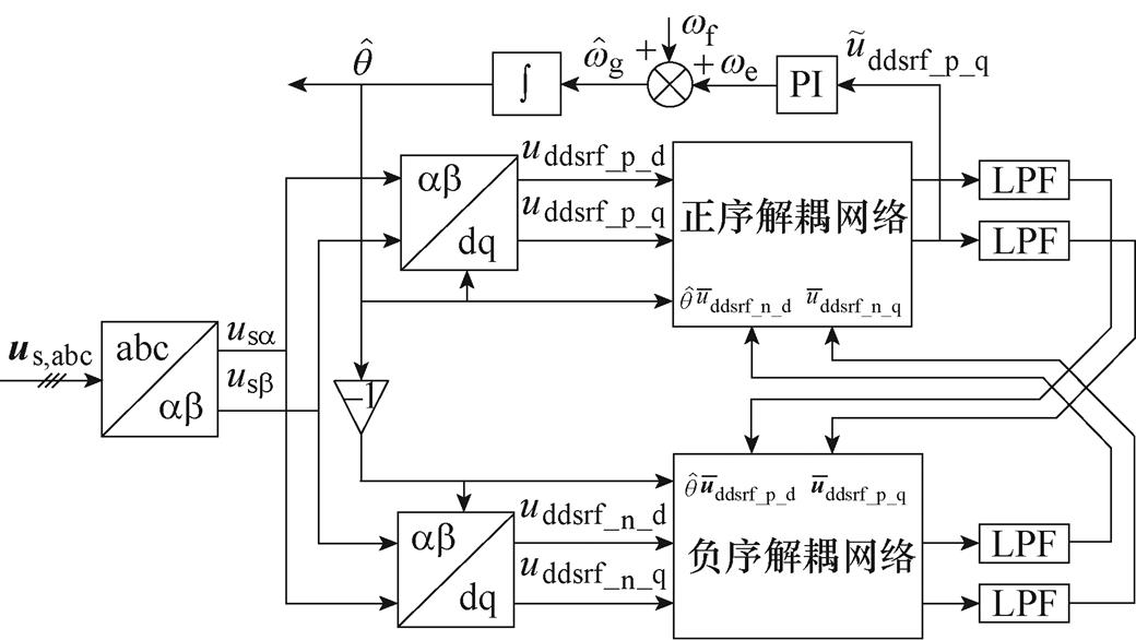
图1 解耦双同步坐标系锁相环的结构框图
Fig.1 Structure diagram of DDSRF-PLL
文献[18-19]采用的DSOGI-PLL结构框图如图2所示。图2中, 与
与 、
、 与
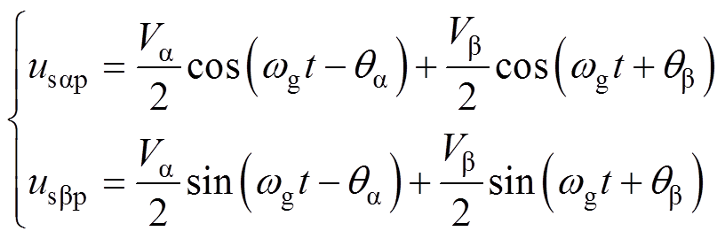
与 分别为经两个SOGI环节生成的a、b 轴的两对正交信号;usap和usbp分别为a、b 轴的三相电压正序分量;udsogi_p_d和udsogi_p_q分别为在DSOGI-PLL下正序旋转坐标系下的d、q轴分量。
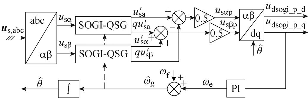
图2 双二阶积分器锁相环的结构框图
Fig.2 Structure diagram of DSOGI-PLL
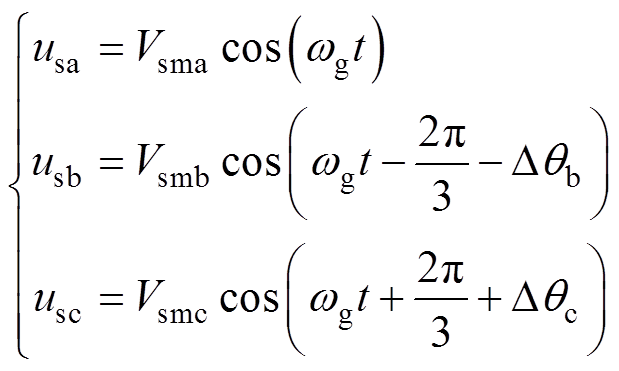
国标将三相电压不平衡阐述为幅值和相位两方面的不平衡[32]。由于谐波和直流分量等可通过滤波器消除,这里仅考虑三相不平衡电压为
 (1)
(1)
式中,usa、usb、usc分别为A相、B相及C相电压;Vsma、Vsmb、Vsmc分别为其对应的幅值;wg为电压角频率;Dqb、Dqc分别为以A相电压相位为基准的B相和C相的不平衡电压相位。
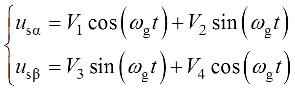
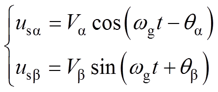
将式(1)所示的包含幅值和相位不平衡的三相电压作为DDSRF-PLL与DSOGI-PLL两种方法的输入信号,并以A相电压定向,可得到式(1)的两相静止坐标系表示为
 (2)
(2)
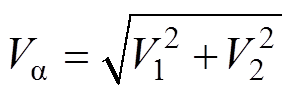
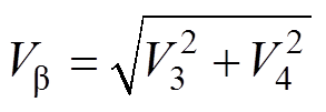
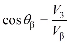
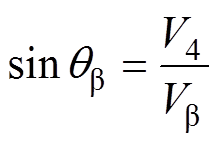
式中,V1~V4为中间变量,是关于Vsma、Vsmb、Vsmc以及Dqb、Dqc的函数,其表达式如附录式(A1)~式(A4)所示。
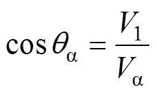
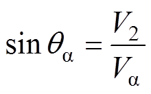
进一步地,利用辅助角公式,可将式(2)整理为
 (3)
(3)
其中
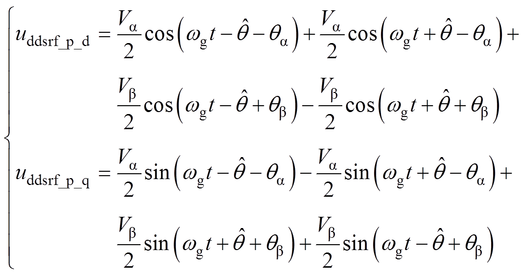
对于DDSRF-PLL,通过正、负同步旋转坐标系结合解耦网络和低通滤波器实现谐波分量的滤除和基波正、负序分量的分离[13-15]。基于d轴电压定向,可得到正、负同步旋转坐标变换后的信号,分别为
 (4)
(4)
 (5)
(5)
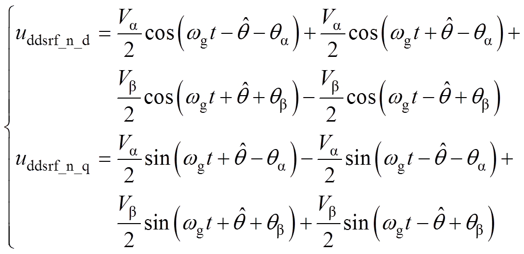
经解耦网络消去式(4)和式(5)的二倍频分量后,可得
 (6)
(6)
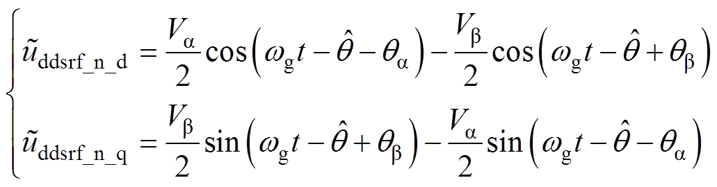 (7)
(7)
由于解耦网络仅消除正、负序同步旋转坐标系下由负序、正序产生的二倍频分量,而在实际中,由于输出信号可能存在谐波分量,故式(6)和式(7)输出信号中可能含有谐波分量,这里用上标“ ”加以区分。
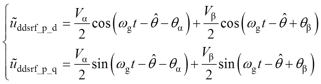
同理,在式(3)的基础上,根据式(8)所示的两相静止坐标系下的提取正序分量的对称分量法表达式[19],可得到基于DSOGI-QSG的两相静止坐标系下的正序电压分量如式(9)所示。
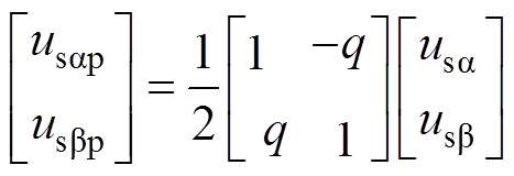 (8)
(8)
 (9)
(9)
式中,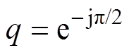 ,该算子表示在原基础上相位滞后90 °,j为虚数单位。
同样地,可得到DSOGI-PLL的正序电压分量在正序同步旋转坐标系下的表达式为
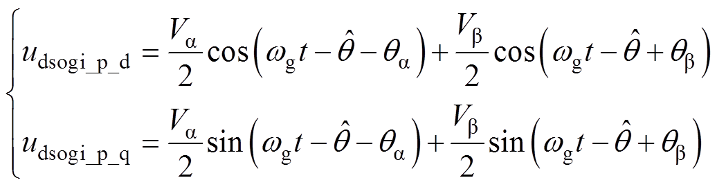 (10)
(10)
DDSRF-PLL与DSOGI-PLL均是通过将正序电压分量的q轴分量调节为零实现锁相[11],即前者将式(6)所示的 控制为零,而后者将式(10)所示的
 控制为零。可看出,两种锁相方法实际的锁相输入信号具有相同的表达形式,表明二者在三相电压不平衡工况下的锁相具有理论上的等价性。而实际中,特别是锁相的暂态过程,由于DDSRF-PLL的解耦网络和低通滤波器并不能完全消除二倍频分量[13],同时DSOGI环节提取的正序分量也具有误差[16, 19],会使得两种方法的锁相结果具有一定差异。同时,从式(6)的和式(10)的表达式可看出,幅值和相位不平衡的三相电压会使得两式中的信号存在两部分,从而导致估测相位较实际相位
 存在锁相误差。通常以A相电压为基准,故而用来表征A相电压估测相位,由于其存在锁相误差,使得式(11)所示B、C相的估测相位也存在误差,并导致三相电压的锁相均存在较大偏差。
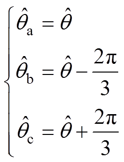 (11)
(11)
式中, 、
、 、
、 分别为各相的相位估测值。
为获得三相不平衡电压下的锁相误差,根据锁相的稳态关系,将式(6)或式(10)的q轴分量调节至零。由于两种锁相环的表达形式一致,这里统一记为usq,令其为零并经三角函数恒等变换,可得
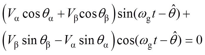 (12)
(12)
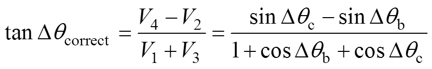
将锁相误差记为Dqcorrect,则有 ,代入式(12),并整理为正切函数形式,可得
 (13)
(13)
进一步地,由于三相锁相环常对每相电压进行幅值标幺化以消除幅值不平衡的影响[33],从而保证锁相环控制精度。为便于分析,这里将Vsma、Vsmb、Vsmc取为1,后续以上标“*”表示幅值标幺化。结合附录中式(A1)~式(A4),可将式(13)简化为
 (14)
(14)
式(14)表明,Dqcorrect与Dqb、Dqc具有映射关系。
将Dqcorrect作为因变量,Dqb、Dqc作为自变量,经反正切运算,可得式(15)所示的Dqcorrect与Dqb和Dqc的关系。由于反正切函数的值域为[-p/2, p/2],且实际的相位不平衡程度有限,这里以Dqb、Dqc在[-p/6, p/6]内的情形分析。
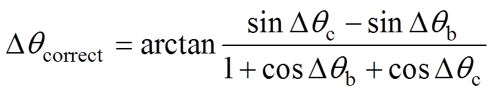 (15)
(15)
由式(15)可绘制出Dqcorrect=f(Dqb, Dqc)的三维图形,如图3所示。为直观显示,图3的坐标单位以角度标注。通过分析图3的曲面关系,有如下结论:
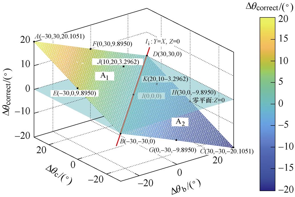
图3 Dqcorrect与Dqb、Dqc的三维关系曲面
Fig.3 Three-dimensional surface with Dqb and Dqc
(1)不平衡相位在 范围内变化时,锁相误差最大为
 ,如图3中的A点和C点。
(2)锁相误差曲面近似为平面,并与零平面相交于直线li:Dqb=Dqc,Dqorrect=0,如图3中的B点、D点和I点,表明Dqb和Dqc取值相等时,不会产生锁相误差。而且该曲面以直线li为界,当处于直线li上方的A1区域时,Dqb<Dqc,Dqcorrect>0;而处于li下方的A2区域时,Dqb>Dqc,Dqcorrect<0。
(3)该曲面上关于直线li轴对称的点,Dqcorrect的幅值相同,符号相反,如图3中的J点与K点。
(4)处于曲面与直线li平行直线上的点,它们的Dqcorrect取值相等,如图3中的E点和F点以及G点和H点。
基于式(15)可得到精确的Dqcorrect,但需求解多次三角函数运算。为简化计算,这里给出三种近似算法,并对其近似合理性予以评估。首先,可将式(15)的反正切函数近似,得到式(16),这里称其为一阶近似,得到的锁相误差记为 。由于反正切函数在定义域内单调递增,考虑Dqcorrect为的情形,此时对应弧度为±0.350 9 rad,而基于式(16)得到的近似值为±0.366 0 rad,最大误差为±0.015 1 rad(
 ),误差率仅为4.3 %,满足精度要求。若进一步对式(16)中的余弦和正弦函数进行近似,可得式(17),这里称其为二阶近似,并将得到的锁相误差记为
 。此时,近似值为±0.349 1 rad,最大误差为±0.018 rad(
 ),误差率为5.13 %,仍具有较高精度。
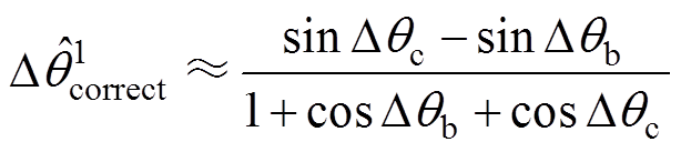 (16)
(16)
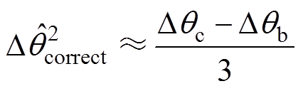 (17)
(17)
上述近似方法在曲面两端的近似误差较大,为减小该误差,可采用平面近似方法,并将其获得的锁相误差记为 。该方法将曲面划分为有限个小平面,可根据曲面的弯曲程度灵活调整。由于曲面两端误差最大,可选择平行于li的直线,重新划分图3的A1、A2区域,如图4所示。这里仅以
 为划分区域的界限进行说明,即 图中的E、F和G、H。
 为A1区域,
 为A2区域,
 为A3区域,每个小区域可由三点坐标进行确定。如果要求近似精度较高,可将A2、A3区域进行多次划分,直至A2n、A2n+1区域,同时可根据需要调整E、F和G、H的位置。
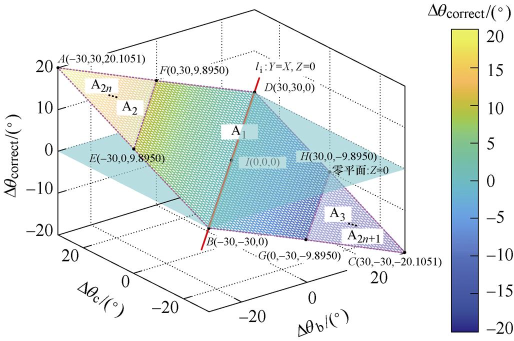
图4 Dqcorrect的平面近似方法
Fig.4 Plane approximation method of Dqcorrect
图4所示的平面近似方法以点E、F、I确定区域A1,以点A、E、F确定区域A2,并由点C、G、H确定区域A3。因此,可以很容易地得到区域A1、区域A2和区域A3的数学表达式分别为
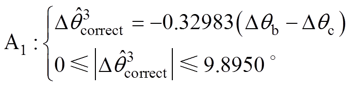 (18)
(18)
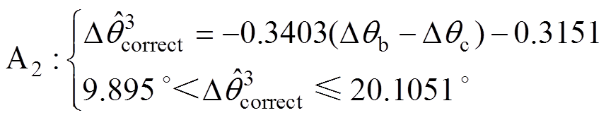 (19)
(19)
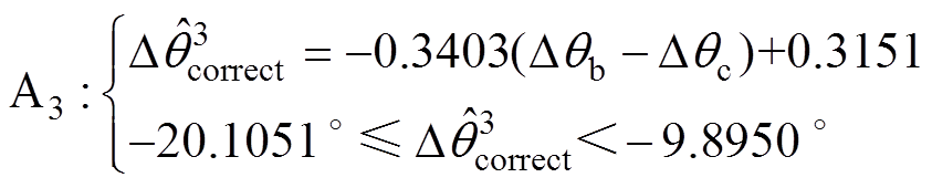 (20)
(20)
基于上述的锁相误差的精确计算方法以及三种近似方法,可求解得到Dqcorrect,将其与反向叠加,便可实现三相不平衡电压下估测相位的补偿校正。
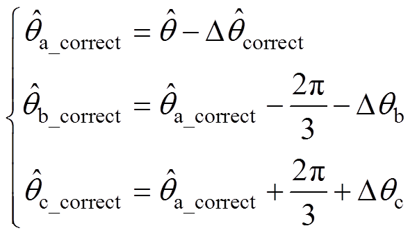 (21)
(21)
式中,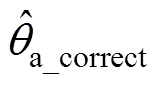 、
、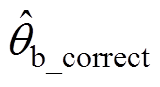 、
、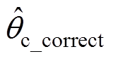 分别为A、B、C三相校正后的估测相位值。
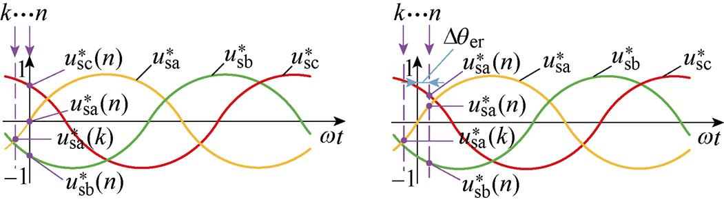
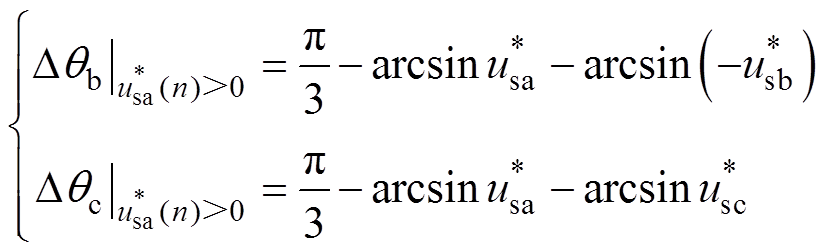
式(21)表明,获取Dqb与Dqc是消除A相估测相位误差以及补偿B、C两相相位的关键。因此,实现锁相误差的补偿,首先要检测得到不平衡相位。以正弦电压为例,将A相电压过零点作为计算基准,分别检测B、C两相的相位,便可得到Dqb、Dqc的值。在采样频率固定的情况下,假设k时刻A相电压小于零,经过一段时间的采样后,n时刻会出现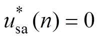 或是
或是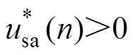 两种情况,分别如图5a和图5b所示。图中,k和n表示不同采样时刻;
 、
、 、
、 为幅值标幺化的三相电压瞬时值;Dqer为因A相电压大于零而引入的相位差。
(a)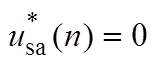 (b)
(b)
图5 Dqb与Dqc检测中的电压采样情形
Fig.5 Voltage sampling in the detection of Dqb and Dqc
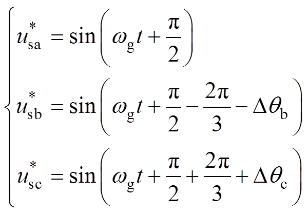
将式(1)进行三角恒等变换为正弦形式,并考虑幅值标幺化,可得三相电压表达式为
 (22)
(22)
由于图5a的A相电压刚好过零,根据式(22)对B、C两相信号化简后,通过对、进行反正弦运算可很容易求得Dqb和Dqc分别为
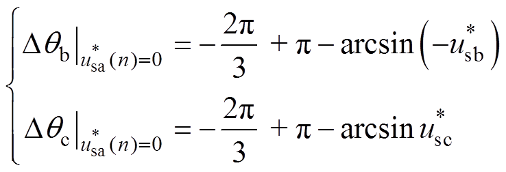 (23)
(23)
实际中更为普遍的是图5b所示的情形。此时,在式(23)的基础上需减去Dqer,该值为 。由于采样频率足够高,Dqer为略大于0的正值,故可得到不平衡相位为
 (24)
(24)
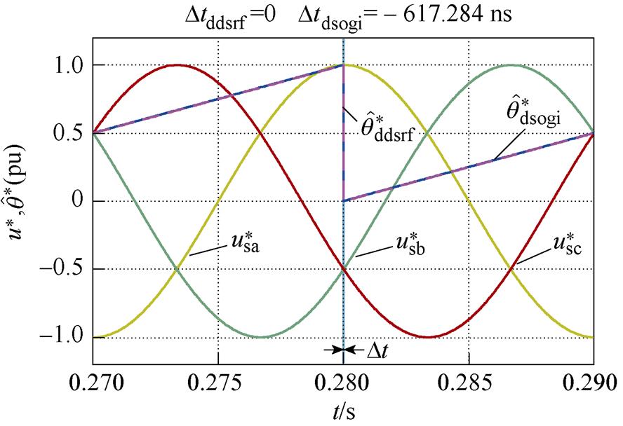
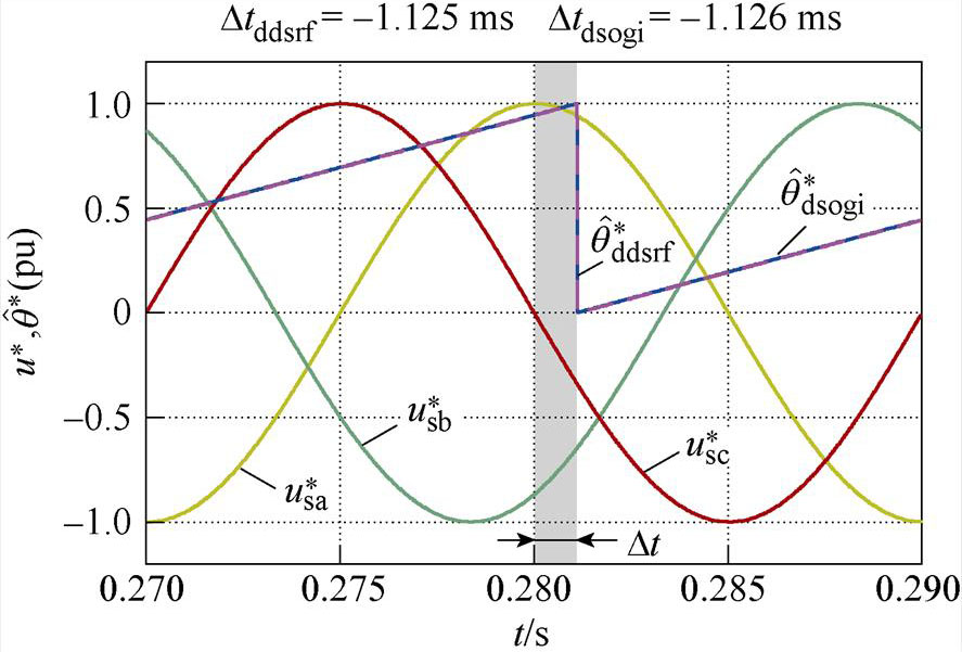
为验证理论分析的正确性,搭建Matlab仿真模型,并将不同Dqb和Dqc取值下的三相电压和两种锁相方法的锁相结果进行仿真如图6所示。
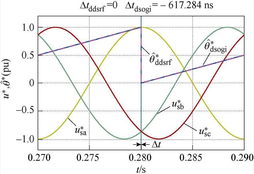
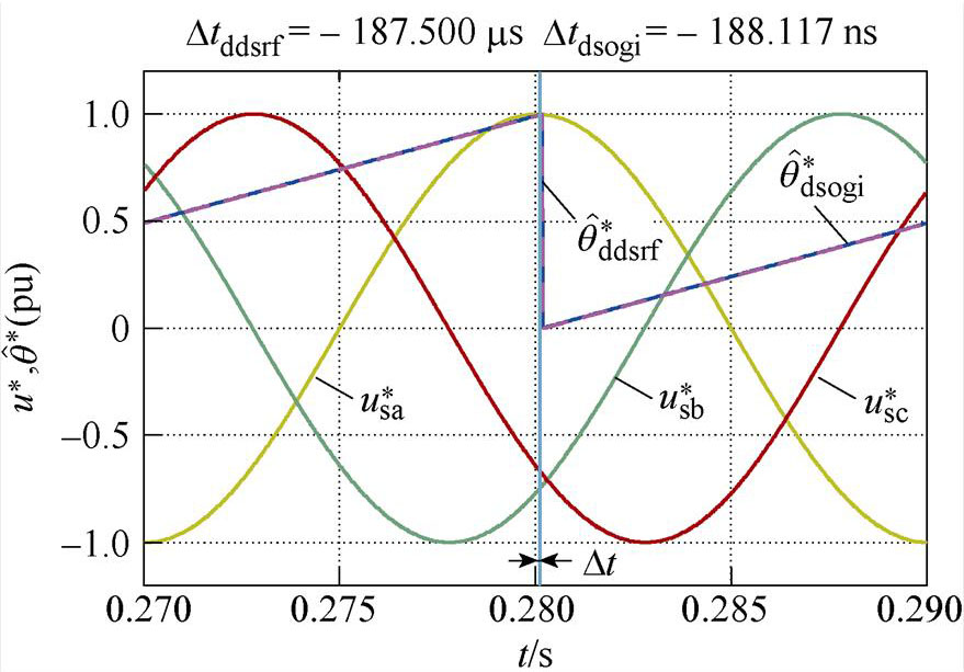
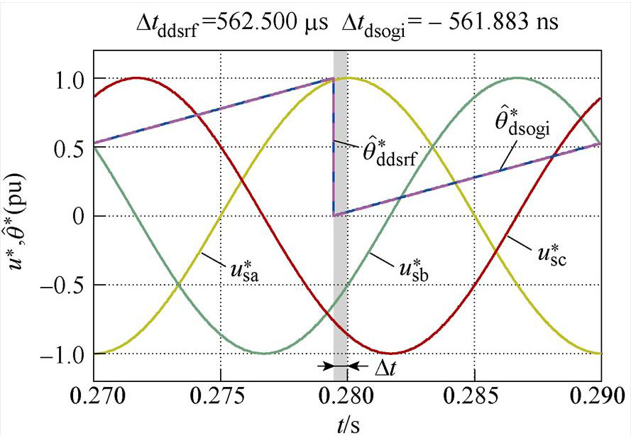
图6各图中曲线分别为单位幅值的三相电压波形(、、)和两种锁相环经相位标幺化后的相位估测结果( ,
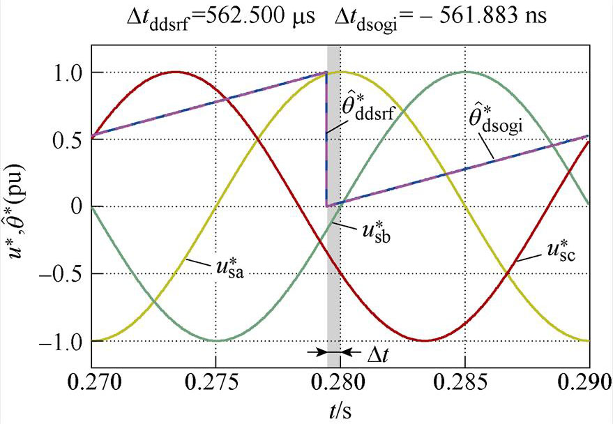
, )。同时将两种锁相环的相位估测曲线相对于0.28 s时的时间差,用Dtddsrf和Dtdsogi分别标注于各图上方。图6a和图6b分别为相位平衡以及不平衡相位为30 °时的锁相结果,可看出两种锁相环基本不产生锁相误差,表明不平衡相位取值相等时,不会产生锁相误差;图6c和图6d表明,当不平衡相位取值关于直线li轴对称时,锁相误差互为相反数;图6e和图6f表明,不平衡相位取值处于与直线li平行直线上的点时,产生的锁相误差相等;图6g和图6h表明,不平衡相位取值处于锁相误差曲面的A点和C点时,具有最大的锁相误差;这与不平衡相位与锁相误差内在关系的理论分析一致。此外,每种相位不平衡工况下Dtddsrf与Dtdsogi的值基本一致,验证了两种锁相环在相位不平衡下的具有锁相等价性的结论。
(a)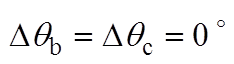
(b)
(c)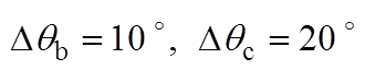
(d)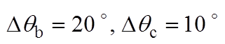
(e)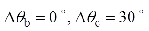
(f)
(g)
(h)
图6 相位不平衡下DDSRF和DSOGI-PLL的仿真结果
Fig.6 Simulation results of DDSRF and DSOGI-PLL at unbalanced phase angles
为便于对比,这里将基于式(15)计算的Dqcorrect理论值、Dtddsrf与Dtdsogi对应的Dqddsrf和Dqdsogi仿真值以及仿真值与理论值的最大误差绝对值 整理见表1。由表1最后一列数据可知,最大误差为0.23 °,此时理论值为9.895 °,误差率仅为2.3 %,表明不平衡相位与锁相误差内在关系理论分析的正确性。该误差是由于理论值根据PI控制器将相位差调节为零的稳态特性获得,而实际上PI控制器达到稳态时,实际值会在给定值附近小范围波动[11],无法完全达到理论上的控制效果。因此,锁相误差理论值与仿真实测值会存在较小的差异。
表1 相位不平衡下两种锁相环的锁相数据
Tab.1 Data of two PLLs at unbalanced phase angles (单位: °)
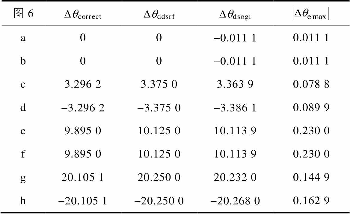
图6DqcorrectDqddsrfDqdsogi a00-0.011 10.011 1 b00-0.011 10.011 1 c3.296 23.375 03.363 90.078 8 d-3.296 2-3.375 0-3.386 10.089 9 e9.895 010.125 010.113 90.230 0 f9.895 010.125 010.113 90.230 0 g20.105 120.250 020.232 00.144 9 h-20.105 1-20.250 0-20.268 00.162 9
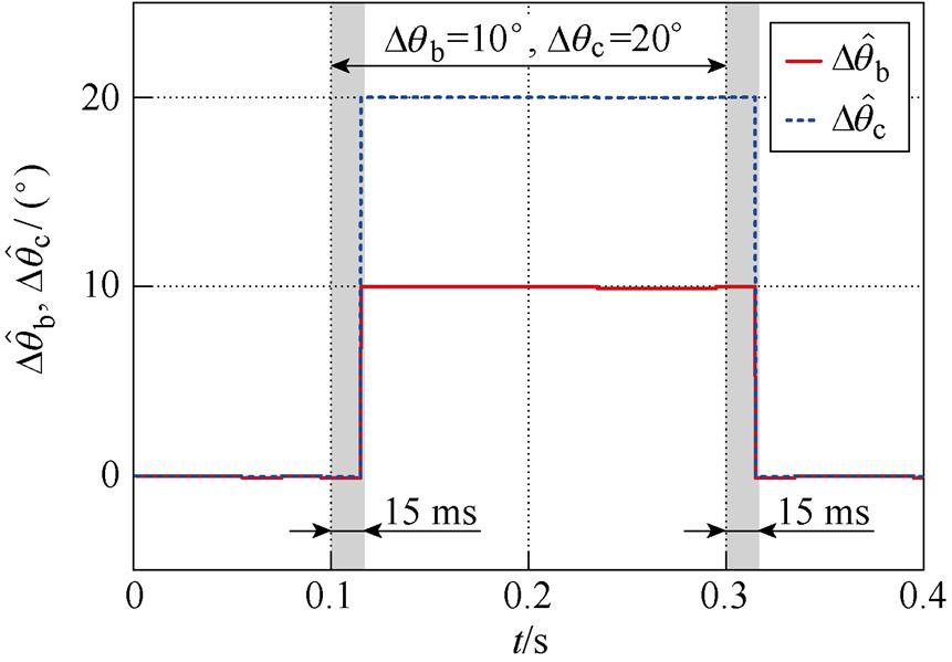
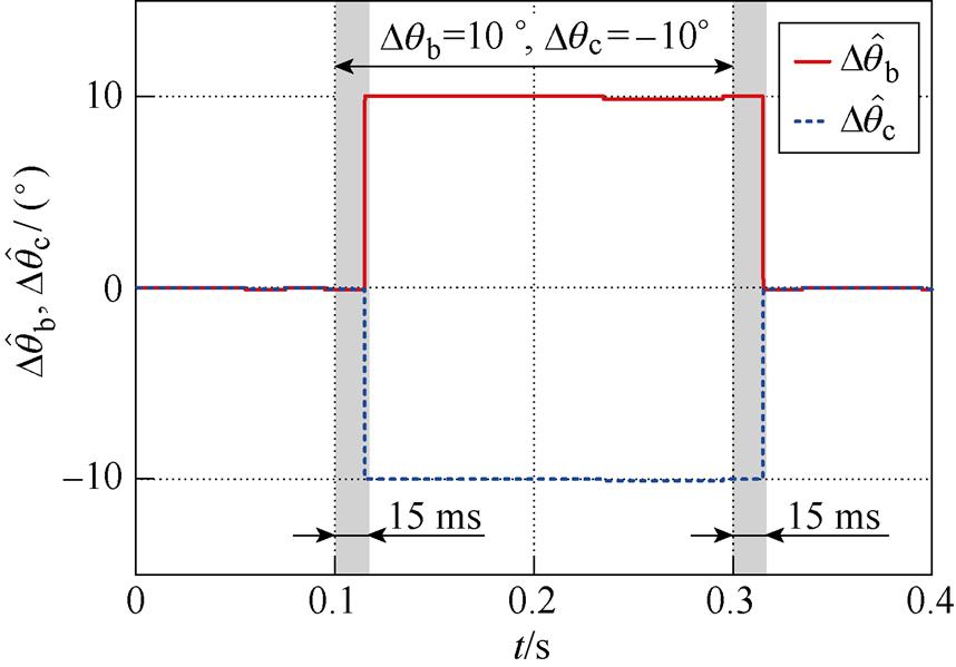
为验证2.3节的不平衡相位检测方法,在0.1~0.3 s设置相位阶跃工况。 ,
, 以及,
以及, 的不平衡相位检测结果如图7所示,图7中,
 和
和 分别为
分别为 和
和 的检测值。该图表明,所提检测方法可实现不平衡相位的精确检测,但存在约15 ms的滞后。
(a)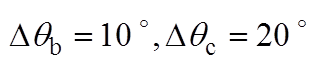
(b)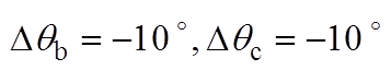
图7 不平衡相位的检测结果
Fig.7 Detection results of unbalanced phase angle
在获得不平衡相位后,基于式(15)可得到精确的Dqcorrect,然后根据式(21)可实现相位补偿。这里以图6h所示工况下DSOGI-PLL的锁相结果为例进行仿真,结果如图8所示。图8的波形从上到下依次为单位幅值的三相电压( 、
、 、
、 )、相位补偿前的余弦值(
 、
、 、
、 )以及相位补偿后的余弦值(
 、
、 、
、 ),其中Dta、Dtb、Dtc为相位补偿前各相的相位差值,Dta_correct、Dtb_correct、Dtc_correct则为相位补偿后各相的相位差,且均以时间表示。补偿前:Dta=-1.126 ms, Dtb=521.883 ms, Dtc=561.883 ms;补偿后:Dta_correct=-9.05 ms, Dtb_correct=-27.883 ms, Dtc_correct= 12.167 ms。
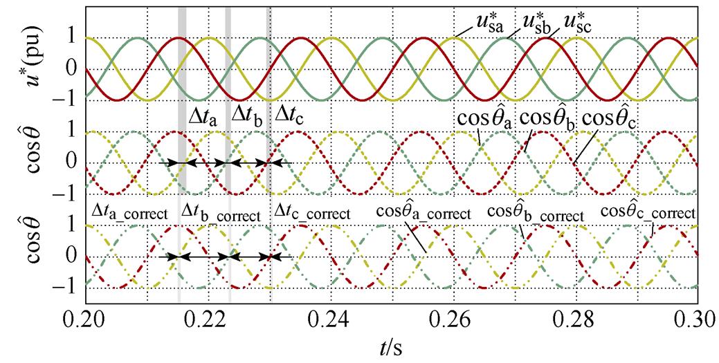
图8  时,经相位补偿前后的DSOGI-PLL的锁相结果
Fig.8 The phase lock results of DSOGI-PLL before and after phase compensation at
图8表明,经相位补偿后的三相电压与实际电压基本同相位,最大误差小于28 ms。相较于补偿前,存在1.126 ms滞后,对应相位差为 ,按照理论值
 补偿,补偿后误差为
 ,仅滞后9.05 ms;对B相来说,超前电压521.883 ms,即
 ,而理论相差为
 ,二者误差为
 ,补偿后仅滞后27.833 ms;而C相的超前电压561.883 ms,即
 ,理论相差为,误差为
 ,对应超前12.167 ms。上述仿真结果表明,三相电压相位不平衡时,DSOGI-PLL存在较大的锁相误差;经过相位补偿后,相位差均小于,表明所提锁相误差补偿方法可显著提高DSOGI-PLL等锁相方法在相位不平衡下的锁相精度。
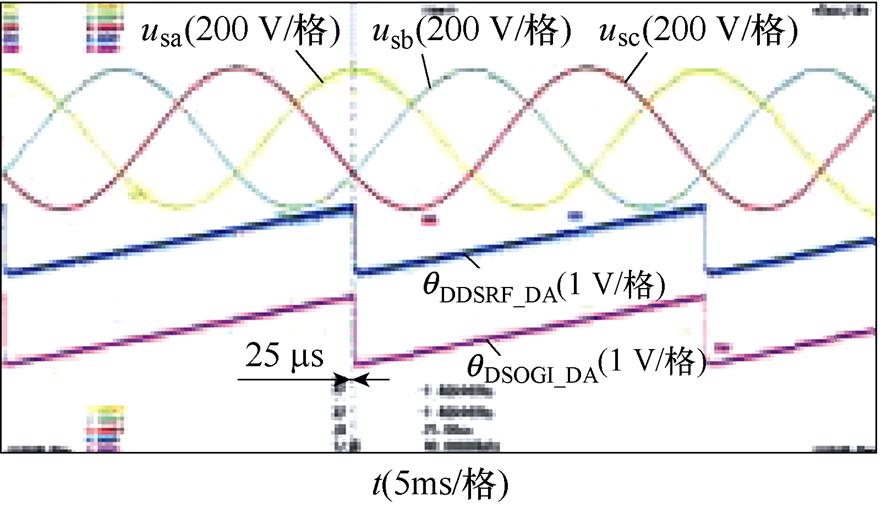
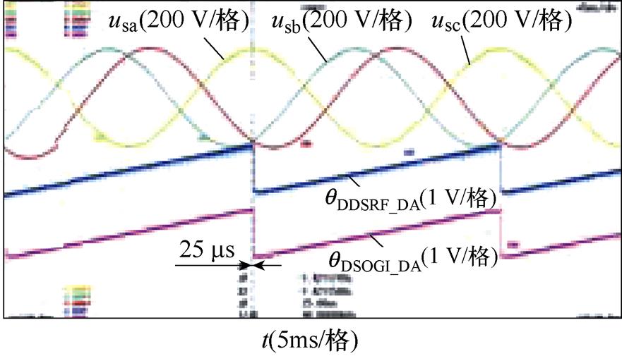
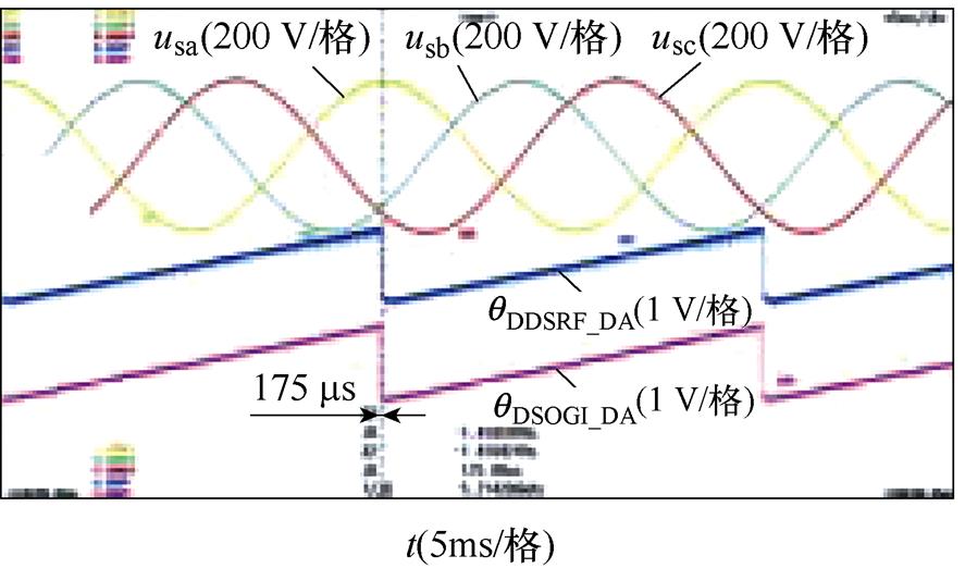
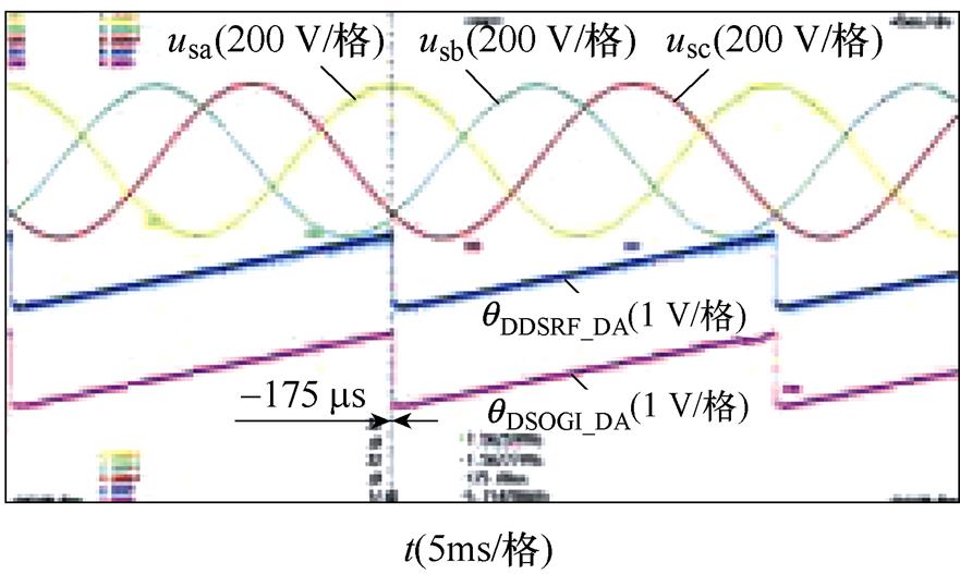
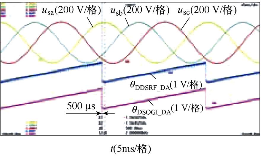
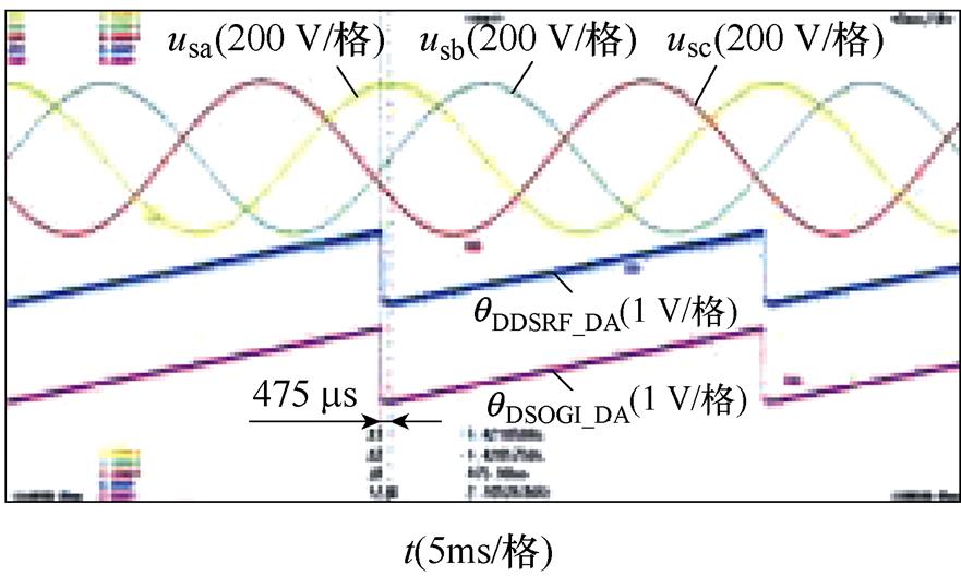
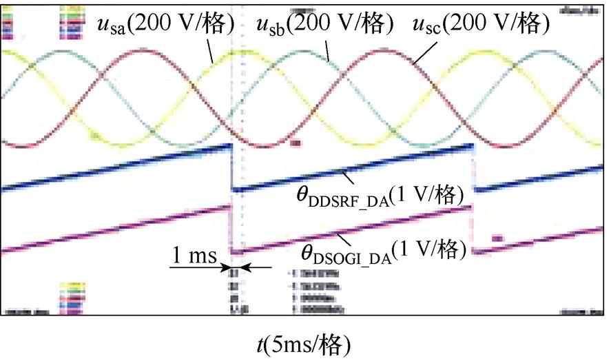
相位不平衡下DDSRF-PLL和DSOGI-PLL的实验结果如图9所示。图9中的不平衡工况分别按照图6的仿真工况设置,每个图中的波形从上至下依次为并网点三相电压波形(usa, usb, usc)、DDSRF- PLL估测相位的DA值(qDDSRF_DA)以及DSOGI-PLL估测相位的DA值(qDSOGI_DA)。其中,相位不平衡的三相电压由Chroma 61705型三相可编程电压源产生。图9的实验结果与图6的仿真结果基本一致,仅在数值上有微小差异,表明DDSRF-PLL及DSOGI- PLL两种锁相方法在三相电压相位不平衡下锁相的等价性,同时验证了锁相误差与不平衡相位内在关系的理论分析。
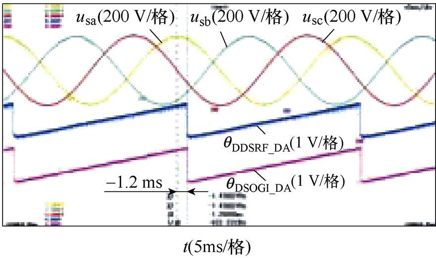
进一步地,选择图9h所示的锁相误差最大的情形,并以DSOGI-PLL为例,对本文提出的不平衡相位检测和补偿方法进行实验,相位补偿前后的实验结果如图10所示。图10中,各图波形从上至下依次为并网点三相电压波形(usa, usb, usc)和对应估测相位的余弦值(cosqa_DA, cosqb_DA, cosqc_DA),其中后者通过数模转换(DA)读出。图10a和图10b表明,补偿后相较于补偿前相位滞后1.425 ms,精确补偿后相位滞后仅为75 ms;而图10c~图10e则表明,基于一次、二次以及平面近似的方法补偿后相位滞后分别减小为250 ms、325 ms和225 ms。这说明精确补偿具有最高的补偿精度;而近似算法则以略低的补偿精度为代价实现了简化计算,选择时需要对补偿精度和计算量进行折中。
(a)
(b)
(c)
(d)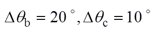
(e)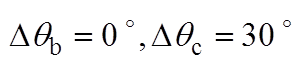
(f)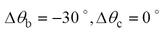
(g)
(h)
图9 相位不平衡下DDSRF和DSOGI-PLL的实验结果
Fig.9 Experimental results of DDSRF and DSOGI-PLL at unbalanced phase angles
(a)相位未补偿
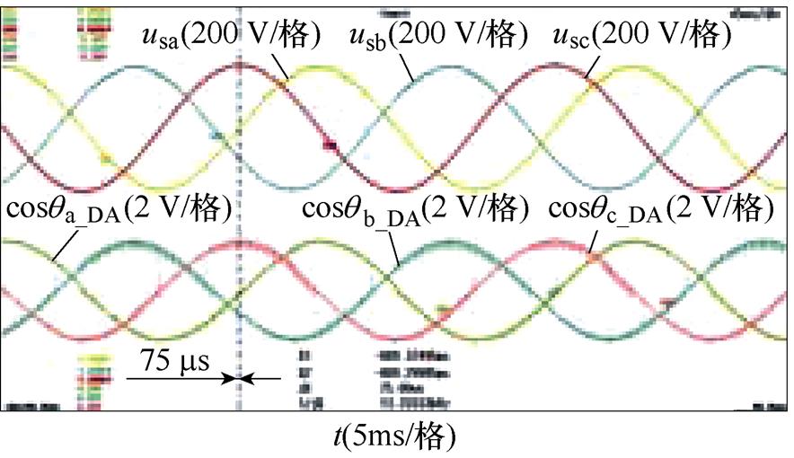
(b)精确补偿
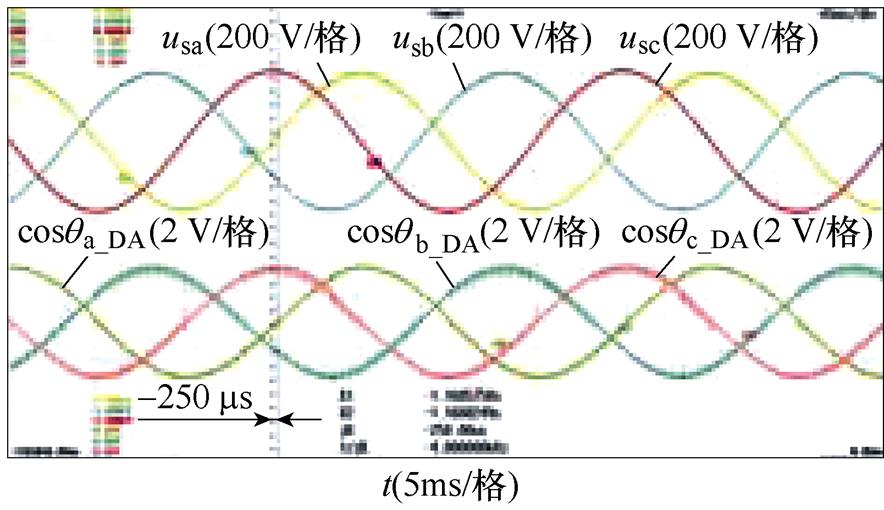
(c)一次近似补偿
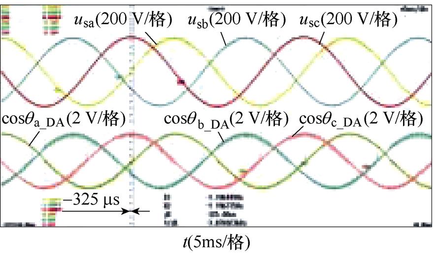
(d)二次近似补偿
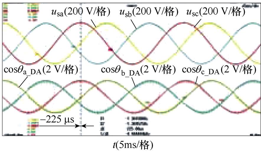
(e)平面近似补偿
图10 相位补偿前后的实验结果
Fig.10 Experimental results before and after phase compensation
本文以DDSRF-PLL和DSOGI-PLL这两种常用于三相电压幅值不平衡的锁相方法为基础,考虑幅值和相位两方面的不平衡,论证了二者的锁相等价性,并说明电压相位不平衡会导致二者存在固有锁相误差。针对该问题,本文基于锁相环的稳态特性,在理论推导的基础上,揭示了锁相误差和不平衡相位的内在关系,进而提出锁相误差的求解方法和不平衡相位的检测方法,并通过仿真和实验验证了所提方法的准确性。本文揭示的锁相误差和不平衡相位的内在关系为三相电压相位不平衡工况下的精确锁相提供了一种行之有效的理论依据。所提的不平衡相位检测和锁相误差补偿方法,通过对三相电压采样值进行反正弦运算检测不平衡相位,并根据其与锁相误差的关系实现相位补偿。该方法结构简单、易拓展且补偿精度高,对相位不平衡下的精确锁相有着一定的实用价值。
附 录
为便于表述,这里将式(2)中的V1~V4表示为
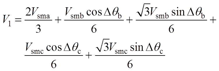 (A1)
(A1)
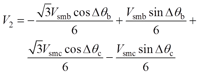 (A2)
(A2)
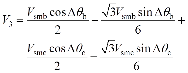 (A3)
(A3)
 (A4)
(A4)
参考文献
[1] 杨珺, 侯俊浩, 刘亚威, 等. 分布式协同控制方法及在电力系统中的应用综述[J]. 电工技术学报, 2021, 36(19): 4035-4049.
Yang Jun, Hou Junhao, Liu Yawei, et al. Distributed cooperative control method and application in power system[J]. Transactions of China Electrotechnical Society, 2021, 36(19): 4035-4049.
[2] 沈霞, 帅智康, 沈超, 等. 大扰动时交流微电网的运行与控制研究综述[J]. 电力系统自动化, 2021, 45(24): 174-188.
Shen Xia, Shuai Zhikang, Shen Chao, et al. Review on operation and control of AC microgrid under large disturbance[J]. Automation of Electric Power Systems, 2021, 45(24): 174-188.
[3] 余墨多, 黄文焘, 邰能灵, 等. 逆变型分布式电源并网运行暂态稳定机理与评估方法[J]. 电工技术学报, 2022, 37(10): 2596-2610.
Yu Moduo, Huang Wentao, Tai Nengling, et al. Transient stability mechanism and judgment for inverter interfaced distributed generators connected with public grids[J]. Transactions of China Elec- trotechnical Society, 2022, 37(10): 2596-2610.
[4] 王宝诚, 伞国成, 郭小强, 等. 分布式发电系统电网同步锁相技术[J]. 中国电机工程学报, 2013, 33(1): 50-55.
Wang Baocheng, San Guocheng, Guo Xiaoqiang, et al. Grid synchronization and PLL for distributed power generation systems[J]. Proceedings of the CSEE, 2013, 33(1): 50-55.
[5] 陈明亮, 肖飞, 刘勇, 等. 一种正负序分离锁相环及其在并网型风力发电系统中的应用[J]. 电工技术学报, 2013, 28(8): 181-186.
Chen Mingliang, Xiao Fei, Liu Yong, et al. A positive and negative-sequence detection PLL and its appli- cation in wind power generation system[J]. Transa- ctions of China Electrotechnical Society, 2013, 28(8): 181-186.
[6] 王国玲, 何富桥, 刘旭, 等. 基于二阶广义积分器新能源船舶电网锁相技术[J]. 电机与控制学报, 2020, 24(7): 147-155.
Wang Guoling, He Fuqiao, Liu Xu, et al. Phase- locked loop technique in new energy shipboard grid based on second-order generalized integrators[J]. Electric Machines and Control, 2020, 24(7): 147-155.
[7] 曾君, 岑德海, 陈润, 等. 针对直流偏移和谐波干扰的单相锁相环[J]. 电工技术学报, 2021, 36(16): 3504-3515.
Zeng Jun, Cen Dehai, Chen Run, et al. Single-phase phase-locked loop for DC offset and harmonic inter- ference[J]. Transactions of China Electrotechnical Society, 2021, 36(16): 3504-3515.
[8] Golestan S, Monfared M, Freijedo F D. Design- oriented study of advanced synchronous reference frame phase-locked loops[J]. IEEE Transactions on Power Electronics, 2013, 28(2): 765-778.
[9] Golestan S, Guerrero J M, Vasquez J C. Three-phase PLLs: a review of recent advances[J]. IEEE Transa- ctions on Power Electronics, 2017, 32(3): 1894- 1907.
[10] Golestan S, Guerrero J M, Vasquez J C, et al. A study on three-phase FLLs[J]. IEEE Transactions on Power Electronics, 2019, 34(1): 213-224.
[11] 岑扬, 黄萌, 査晓明. 电网电压不平衡跌落下同步参考坐标系锁相环瞬态响应分析[J]. 电工技术学报, 2016, 31(增刊2): 28-38.
Cen Yang, Huang Meng, Zha Xiaoming. The transient response analysis of SRF-PLL under the unbalance grid voltage sag[J]. Transactions of China Electro- technical Society, 2016, 31(S2): 28-38.
[12] Sadeque F, Reza M S, Hossain M M. Three-phase phase-locked loop for grid voltage phase estimation under unbalanced and distorted conditions[C]//2017 IEEE Power and Energy Conference at Illinois (PECI), Champaign, IL, USA, 2017: 1-7.
[13] Rodriguez P, Pou J, Bergas J, et al. Decoupled double synchronous reference frame PLL for power con- verters control[J]. IEEE Transactions on Power Electronics, 2007, 22(2): 584-592.
[14] 李珊瑚, 杜雄, 王莉萍, 等. 解耦多同步参考坐标系电网电压同步信号检测方法[J]. 电工技术学报, 2011, 26(12): 183-189.
Li Shanhu, Du Xiong, Wang Liping, et al. A grid voltage synchronization method based on decoupled multiple synchronous reference frame[J]. Transa- ctions of China Electrotechnical Society, 2011, 26(12): 183-189.
[15] Yepes A G, Vidal A, Lopez O, et al. Evaluation of techniques for cross-coupling decoupling between orthogonal axes in double synchronous reference frame current control[J]. IEEE Transactions on Indu- strial Electronics, 2014, 61(7): 3527-3531.
[16] 谢门喜, 朱灿焰, 杨勇. SRF-PLL环内应用二阶广义积分器的不平衡电压锁相方法[J]. 电气工程学报, 2017, 12(9): 16-21.
Xie Menxi, Zhu Canyan, Yang Yong. SRF-PLL with ln-loop second order generalized integrator for unba- lanced three-phase systems[J]. Journal of Electrical Engineering, 2017, 12(9): 16-21.
[17] 张纯江, 赵晓君, 郭忠南, 等. 二阶广义积分器的三种改进结构及其锁相环应用对比分析[J]. 电工技术学报, 2017, 32(22): 42-49.
Zhang Chunjiang, Zhao Xiaojun, Guo Zhongnan, et al. Three improved second order generalized integrators and the comparative analysis in phase locked loop application[J]. Transactions of China Electrotechnical Society, 2017, 32(22): 42-49.
[18] 闫培雷, 葛兴来, 王惠民, 等. 弱电网下新能源并网逆变器锁相环参数优化设计方法[J]. 电网技术, 2022, 46(6): 2210-2221.
Yan Peilei, Ge Xinglai, Wang Huimin, et al. PLL parameter optimization design for renewable energy grid-connected inverters in weak grid[J]. Power System Technology, 2022, 46(6): 2210-2221.
[19] Rodriguez P, Luna A, Candela I, et al. Multiresonant frequency-locked loop for grid synchronization of power converters under distorted grid conditions[J]. IEEE Transactions on Industrial Electronics, 2011, 58(1): 127-138.
[20] 回楠木, 王大志, 李云路. 基于复变陷波器的并网锁相环直流偏移消除方法[J]. 电工技术学报, 2018, 33(24): 5897-5906.
Hui Nanmu, Wang Dazhi, Li Yunlu. DC-offset elimi- nation method for grid-connected phase-locked loop based on complex notch filter[J]. Transactions of China Electrotechnical Society, 2018, 33(24): 5897- 5906.
[21] 何宇, 漆汉宏, 罗琦, 等. 基于分数阶滤波器的三相锁相环技术[J]. 电工技术学报, 2019, 34(12): 2572-2583.
He Yu, Qi Hanhong, Luo Qi, et al. A novel three- phase phase-locked loop method based on fractional- order filter[J]. Transactions of China Electrotechnical Society, 2019, 34(12): 2572-2583.
[22] 何宇, 漆汉宏, 邓小龙. 基于全复数型滤波器的三相锁相环技术[J]. 电工技术学报, 2021, 36(10): 2115-2126.
He Yu, Qi Hanhong, Deng Xiaolong. A three-phase phase-locked loop technique based on all complex coefficient filter[J]. Transactions of China Electro- technical Society, 2021, 36(10): 2115-2126.
[23] Xin Zhen, Zhao Rende, Mattavelli P, et al. Re- investigation of generalized integrator based filters from a first-order-system perspective[J]. IEEE Access, 2016, 4: 7131-7144.
[24] Gude S, Chu C C. Three-phase PLLs by using frequency adaptive multiple delayed signal can- cellation prefilters under adverse grid conditions[J]. IEEE Transactions on Industry Applications, 2018, 54(4): 3832-3844.
[25] 何宇, 漆汉宏, 邓超, 等. 一种嵌入重复控制内模的三相锁相环的设计与实现[J]. 电工技术学报, 2016, 31(22): 83-91.
He Yu, Qi Hanhong, Deng Chao, et al. A novel three- phase phase-locked loop method based on internal model of repetitive control[J]. Transactions of China Electrotechnical Society, 2016, 31(22): 83-91.
[26] Luo Wei, Wei Dafang. A frequency-adaptive improved moving-average-filter based quasi-type-1 PLL for adverse grid conditions[J]. IEEE Access, 2020, 8: 54145-54153.
[27] Xia Tao, Zhang Xu, Tan Guojun, et al. Synchronous reference frame single-phase phase-locked loop (PLL) algorithm based on half-cycle DFT[J]. IET Power Electronics, 2020, 13(9): 1893-1900.
[28] 余攀, 盛万兴, 钟佩军, 等. 基于三相电压空间矢量的开环锁相方法[J]. 电工技术学报, 2020, 35(16): 3460-3469.
Yu Pan, Sheng Wanxing, Zhong Peijun, et al. An open-loop phase-locked method based on three-phase voltage space vector[J]. Transactions of China Elec- trotechnical Society, 2020, 35(16): 3460-3469.
[29] Hui Nanmu, Luo Zongan, Feng Yingying, et al. A novel grid synchronization method based on hybrid filter under distorted voltage conditions[J]. IEEE Access, 2020, 8: 65636-65648.
[30] Hui Nanmu, Wang Dazhi, Li Yunlu. A novel hybrid filter-based PLL to eliminate effect of input harmo- nics and DC offset[J]. IEEE Access, 2018, 6: 19762- 19773.
[31] Adib A, Mirafzal B. Virtual inductance for stable operation of grid-interactive voltage source inver- ters[J]. IEEE Transactions on Industrial Electronics, 2018, 66(8): 6002-6011.
[32] 国家质量监督检验检疫总局, 中国国家标准化管理委员会. GB/T 15543-2008. 电能质量 三相电压不平衡[S]. 北京: 中国标准出版社, 2009.
[33] Reza M S, Sadeque F, Hossain M M, et al. Three- phase PLL for grid-connected power converters under both amplitude and phase unbalanced conditions[J]. IEEE Transactions on Industrial Electronics, 2019, 66(11): 8881-8891.
[34] Islam M Z, Reza M S, Hossain M M, et al. Three- phase PLL based on adaptive Clarke transform under unbalanced condition[J]. IEEE Journal of Emerging and Selected Topics in Industrial Electronics, 2022, 3(2): 382-387.
[35] Sadeque F, Benzaquen J, Adib A, et al. Direct phase- angle detection for three-phase inverters in asymmet- rical power grids[J]. IEEE Journal of Emerging and Selected Topics in Power Electronics, 2021, 9(1): 520-528.
[36] Islam M Z, Reza M S, Hossain M M, et al. Accurate estimation of phase angle for three-phase systems in presence of unbalances and distortions[J]. IEEE Transactions on Instrumentation and Measurement, 2022, 71: 1-12.
Phase Estimation Error Detection and Compensation Method of DDSRF-PLL and DSOGI-PLL under Three-Phase Voltage Unbalance
Abstract Due to the combined effect of high-permeability distributed power supply and various types of loads, the three-phase voltage of the actual grid-connected point has deviations in amplitude and phase angle. However, phase-locking methods based on single synchronous reference frame phase-locked loop (SSRF-PLL), such as decoupled double synchronous reference frame phase-locked loop (DDSRF-PLL) and double second-order generalized integrator phase-lock loop (DSOGI-PLL), generally ignored these differences, and, hence, only acquiring synchronization information at phase-balanced three-phase voltage. More is needed to support coordinated control among devices at the grid-connected point. Recently, some methods were presented to obtain phase information of three-phase voltage under phase unbalance, but most suffered from high computation costs and poor expansibility. Therefore, a compensation method for phase estimation error is proposed. The phase estimation error can be accurately compensated under phase-balanced three-phase voltage by detecting the unbalanced phase angle deviation of B and C phases.
Firstly, the three-phase unbalanced voltage specified in the national standard is used as the input signal for DDSRF-PLL and DSOGI-PLL, and the equivalent relationship between unbalanced voltage and phase estimation error of the two phase-locked loops is obtained. The functional relationship between phase estimation error and unbalanced phase angle deviation is based on steady-state characteristics. Secondly, three approximate solutions for the phase estimation errors are given to simplify the calculation. Then, based on the zero-crossing point of the A phase, the unbalanced phase angle deviation of B and C phases is obtained by calculating the sample value of three-phase voltage. Finally, precise compensation of phase estimation error can be achieved by substituting the phase angle deviation in the function of phase estimation error, overlaying the output of phase estimation error to the original PLL reversely. The phase angle deviation detection and phase estimation error compensation method can realize open-loop compensation with a low computation cost and good expandability.
Simulation results under eight conditions of phase angle deviation show that the estimated phase curves of two PLLs always coincide when the unbalanced phase angle deviation of B and C phases change within the range of [-30 ° 30 °]. The maximum error between theoretical and simulation values is 0.230 °, and the relative error is only 2.3 %. It proves the rationality of the theoretical equivalence of two PLLs and the validity of the relationship between unbalanced phase angle deviation and phase estimation error. The results also show that the maximum delay time decreased from 1.126 ms to 28 ms, and the corresponding phase estimation error reduced from 20.268 ° to 0.501 °, indicating the method’s high compensation accuracy. The experimental results also have similar conclusions. After the accurate compensation and three approximate methods, the phase estimation error was reduced from 1.425 ms to 75 ms, 250 ms, 325 ms, and 225 ms, respectively. The approximate method has a compromise between compensation accuracy and calculation burden.
The following conclusions can be drawn from the simulation and experimental results: (1) DDSRF-PLL and DSOGI-PLL are theoretically equivalent at phase-unbalanced three-phase voltage. (2) The relationship between phase estimation error and phase angle deviation is derived based on the steady-state characteristics of SSRF-PLL, which is suitable for a series of phase-locked methods based on SSRF-PLL and has a wide range of applications. (3) The proposed phase angle deviation detection and phase estimation error compensation method can realize open-loop compensation by simply calculating the sample value of three-phase voltage, which has the characteristics of low computational cost, easy expansion, and high compensation accuracy.
keywords:Three-phase voltage unbalance, phase-locked loop (PLL), phase angle deviation detection, phase estimation error compensation
中图分类号:TM46
DOI: 10.19595/j.cnki.1000-6753.tces.221770
国家自然科学基金资助项目(52007005)。
收稿日期 2022-09-17
改稿日期 2022-11-11
祁永胜 男,1995年生,硕士研究生,研究方向为电能质量治理、并网变换器控制技术。E-mail: 19121484@bjtu.edu.cn
李 凯 男,1988年生,副教授,硕士生导师,研究方向为电力电子与电力传动、电气工程。E-mail: kaili@bjtu.edu.cn(通信作者)
(编辑 陈 诚)