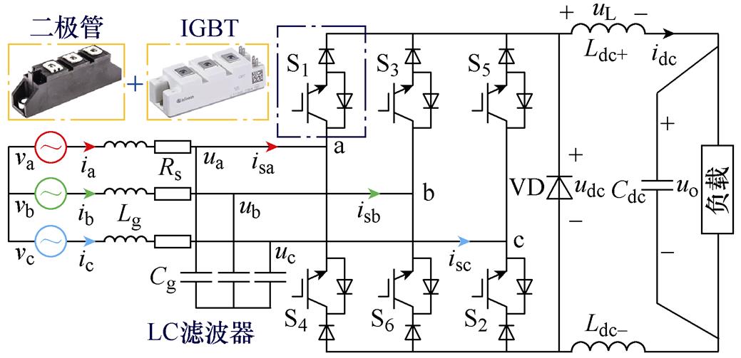
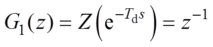
图1 三相CSR电路原理
Fig.1 Circuit schematic of three-phase CSR
摘要 针对三相电流源型PWM整流器直流侧电压-直流侧电流双闭环控制策略中动态响应速度较慢、参数整定复杂的问题,该文提出一种无差拍预测电流控制与负载功率前馈补偿相结合的改进控制策略。首先,分析三相电流源型PWM整流器在两相静止坐标系中的网侧离散化数学模型,在此基础上,电流内环采用无差拍控制跟踪网侧电流,但由于电感参数与控制延时的影响,将导致网侧电流控制精度及波形质量下降。针对此问题,该文采用改进型无差拍控制策略,并利用根轨迹法对电流内环稳定性能进行分析。在环路设计中,通过在外环上加入负载功率前馈等效电流,加快了系统动态响应,解决了负载突变时直流侧电压超调问题。最后,对传统方案和改进方案进行了对比仿真测试和样机实验,验证了所提控制策略的正确性。
关键词:PWM整流器 无差拍控制 功率前馈 预测两拍
脉冲宽度调制(Pulse Width Modulation, PWM)整流器克服了二极管整流器和晶闸管相控整流器网侧电流畸变率大和功率因数低等缺点,已成为电力电子热点研究方向之一[1-2]。PWM整流器分为电压源型整流器(Voltage Source Rectifier, VSR)和电流源型整流器(Current Source Rectifier, CSR)两类,长期以来,VSR以拓扑结构简单、易于控制、低损耗等优点成为PWM整流器研究的重点[3]。然而,在一些特定场合下,CSR因具有降压输出、直接电流控制、谐波电流抑制等优点相较于VSR更具有优势[4-8]。
目前,CSR广泛采用双闭环PI控制,包括直流侧电流-网侧电流双闭环、直流侧电压-直流侧电流双闭环(后文简称:电压-电流双闭环)两种方式[9-10],当三相CSR作为有源前端时,需要对输出电压进行控制,故采用电压-电流双闭环控制[11-14]。文献[11-12]采用电压-电流双闭环控制策略,控制结构虽然简单,但当负载变化时,直流母线电压波动范围较大,其波动幅值大于30 V。文献[13]在双闭环控制策略的基础上,引入电容电压反馈有源阻尼法,改善了网侧电流质量,但当负载变动时其输出电压波动较大。文献[14]中电压外环采用状态反馈控制策略替代了传统PI控制,在交流侧引入虚拟阻抗的控制方法,该控制策略简单、便于实现,但当负载变化时,直流侧输出电压波动幅值增大(约30 V),且恢复时间较长(约30 ms)。由上述文献可知,三相CSR采用电压-电流双闭环控制策略,当负载发生突变时,输出电压均产生较大超调。
VSR中同样存在负载突变时导致直流母线电压超调的问题。针对这一问题,文献[15]提出将电容储能作为外环反馈,并将负载功率进行前馈的控制方法。文献[16]提出一种负载电流前馈控制策略,根据负载扰动瞬时功率关系,将补偿电流与负载电流均作为有功电流补偿进行前馈控制。文献[17]提出一种结合自抗扰和负载功率前馈的电压-电流双闭环控制策略。上述文献通过引入前馈控制有效地改善了因负载突变引起的输出电压波动问题。然而,CSR因直流侧电容取值一般较小,导致电容储能较少,故仅依靠前馈控制改善负载突变时输出电压的波动问题还不够。
无差拍控制(Deadbeat Control, DBC)因具有良好的动态性能、控制精度高、电流跟踪速度快、控制结构简单、易于调试等优点[18-20],已被广泛运用在VSR和Vienna整流器上[21-22]。然而对于CSR整流器,文献[23]采用了电流内环无差拍控制,改善了系统动态性能,但未考虑因控制延时造成的电流预测误差。文献[24]采用无差拍控制跟踪网侧电流,并在外环引入自适应线谱增强器,抑制了系统控制延时带来的误差影响,但该控制方法使控制结构变得复杂,计算量较大。
针对上述文献关于CSR控制策略的不足,本文提出改进型DBC策略。首先,通过分析CSR在ab 两相静止坐标系下的数学模型,推导出CSR改进型DBC策略下z域传递函数;其次,利用根轨迹法对电流内环稳定性能进行分析,通过在内环采用DBC,提高了网侧电流质量,改善了系统动态响应;此外,在电压外环中引入负载功率前馈等效电流,解决了负载突变时输出电压波动过大的问题;最后,通过仿真与实验验证了文中所提控制策略的正确性与可行性。
如图1所示为三相CSR带容性负载的主拓扑电路原理。vx为网侧输入电压,ix为网侧输入电流,ux为交流侧输入电压,isx为交流侧输入电流,x=a, b, c;网侧电感Lg与网侧电容Cg构成LC二阶滤波器与电网相连,用以滤除网侧电流谐波以及整流桥中的高频开关分量;Rs为网侧滤波电感和线路上的等效电阻;将与负载串联的电感Ldc均分为感值相同的Ldc+和Ldc-,既起到了对整流器输出电流的滤波作用,又降低了共模噪声电流;S1~S6为整流器开关功率管;VD为续流二极管,起到简化电路结构以及降低开关器件导通损耗的作用。
图1 三相CSR电路原理
Fig.1 Circuit schematic of three-phase CSR
由图1可得,CSR在abc三相静止坐标系下的数学模型为
 (1)
(1)
通过坐标变换矩阵T3s/2s进行Clarke变换,T3s/2s表示为
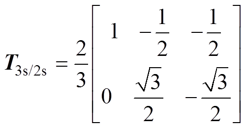 (2)
(2)
得到三相CSR在ab 两相静止坐标系下的数学模型为
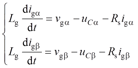 (3)
(3)
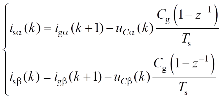
式中,uCa、uCb,vga、vgb,iga、igb 分别为交流滤波电容电压,网侧电压和网侧电流的a 轴、b 轴分量。
三相CSR改进型功率前馈无差拍控制由电压外环PI控制、改进无差拍内环控制以及功率前馈控制三部分组成,系统控制框图如图2所示。
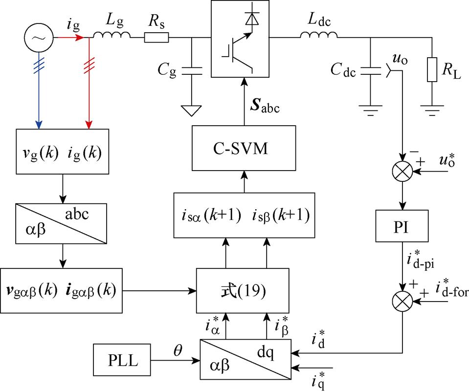
图2 系统控制框图
Fig.2 Block diagram of system control
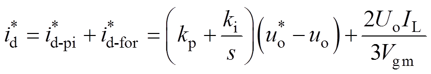
当三相CSR作为有源前端时,其控制目标主要为直流侧电压恒定、网侧电流正弦化及单位功率因数运行。为保证直流侧电压恒定,将直流侧指令电压 与输出电压uo进行比较,其差值作为PI控制器的输入,经过控制器限幅后,作为内环无差拍控制中网侧电流在同步旋转坐标系下d轴的给定电流
 表示为
表示为
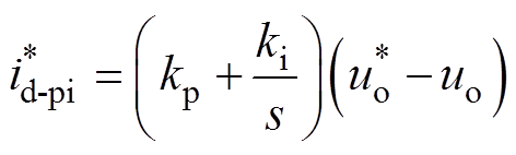 (4)
(4)
式中,kp、ki分别为比例系数和积分系数。
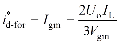
当负载变化时,输出电压将会产生超调现象。对此,通过将直流侧功率进行前馈补偿,得到电流 作为内环电流参考值,提高直流侧输出电压稳定性,并提高响应速度。
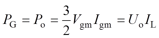
忽略整流器及滤波电路中功率损耗,且假定系统运行在单位功率因数下,根据功率守恒理论[25]得
 (5)
(5)
式中,PG、Po分别为网侧输入有功功率和直流侧输出有功功率;IL为负载电流;Uo为输出电压稳态值;Vgm、Igm分别为网侧输入电压、电流幅值。
 (6)
(6)
根据式(4)和式(6),可获得CSR网侧电流在d轴下的参考电流 为
为
 (7)
(7)
为了保持系统三相CSR单位功率因数运行,令在q轴下的参考电流 =0。
=0。
因本文分析CSR在ab 下的数学模型,则需要将dq坐标系下的网侧参考电流通过Park逆变换得到ab 坐标系下的电流,具体表示为
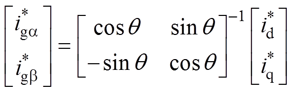 (8)
(8)
DBC是模型预测控制中的一种预测控制方法,即通过当前时刻电流输入量和控制量,预测下一时刻电流量,将该预测电流值给到当前时刻电流给定值,通过构造算法计算占空比,使得网侧电流精确跟踪参考电流,无差拍控制结构如图3所示。
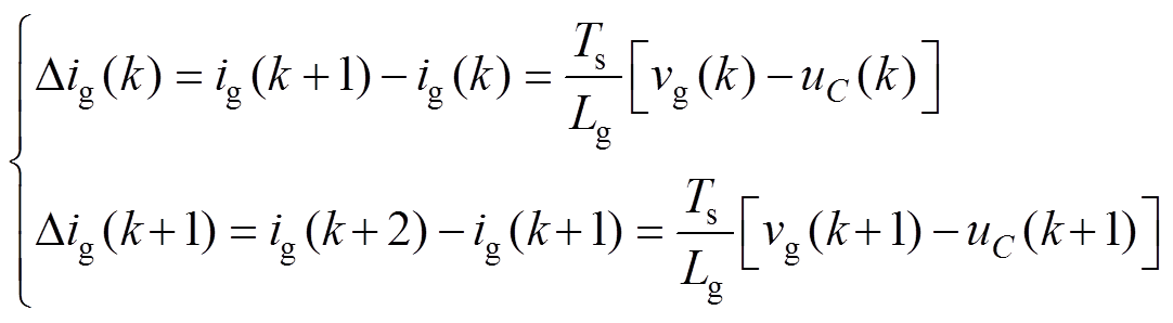
对式(3)采用前向差分运算进行离散化得
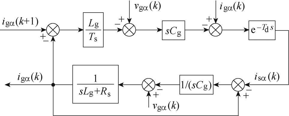
图3 无差拍控制结构
Fig.3 Structure diagram of deadbeat control
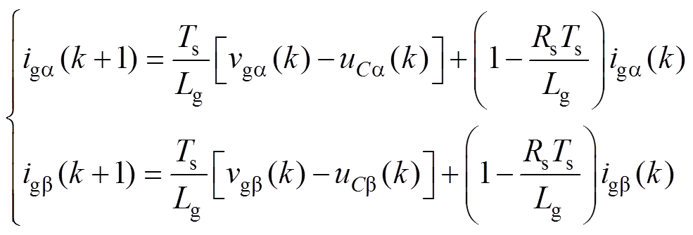 (9)
(9)
式中,Ts为开关周期。
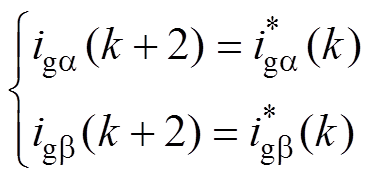
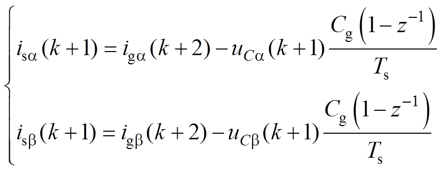
为使k+1时刻电流精确跟踪参考电流,实现无差跟踪,令
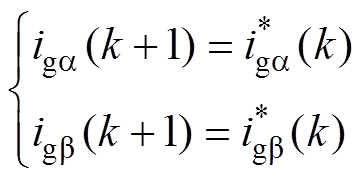 (10)
(10)
式中, 、
、 为k+1时刻的电流采样值;
 、
、 为无差拍控制中ab 坐标系下内环参考电流。
根据式(9)和式(10),可以计算出交流侧滤波电压为
 (11)
(11)
通过基尔霍夫电流定律得出CSR交流侧输入电流为
 (12)
(12)
传统DBC中,由于控制延时的影响,将导致控制量is(k)延迟输出,图4为控制量is(k)的控制延时示意图。
传统DBC理论上假设在第k周期时刻采样、算法运算、占空比输出在同一时间完成,网侧电流ig能完全跟踪指令参考电流 。然而,在实际情况下会存在控制延时的情况,将会影响电流的控制精度,造成网侧电流畸变。
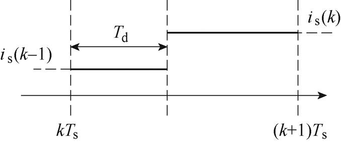
图4 控制延时示意图
Fig.4 Schematic diagram of the control delay
3.1节分析了传统无差拍控制中因控制延时影响,会造成网侧电流畸变。对此,本文采用改进型DBC方法,即预测至k+2时刻。图5为改进型DBC控制延时示意图。
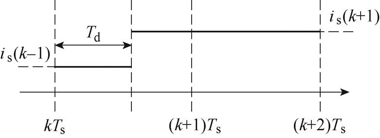
图5 改进算法的控制延时示意图
Fig.5 Schematic diagram of the control delay of the improved algorithm
将式(9)中预测电流再向后推算到k+2时刻,可得
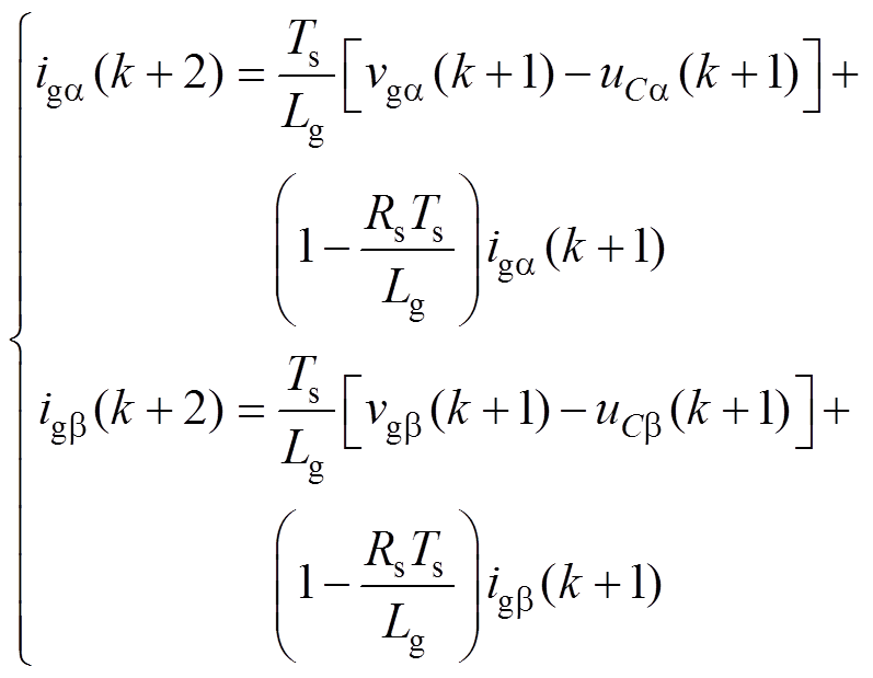 (13)
(13)
此时为了达到无差拍控制的效果,令
 (14)
(14)
为了方便分析计算,忽略网侧滤波电感等效电阻,根据式(9)和式(13)可得到第k时刻和第k+1时刻的电流偏差分别为
 (15)
(15)
通常DBC不存在零误差现象,因此某一时刻电流偏差可等同于相邻时刻电流偏差的平均值,此时第k+1时刻电流偏差为
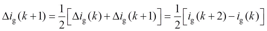 (16)
(16)
整理式(13)~式(16)可得CSR交流侧滤波电压为
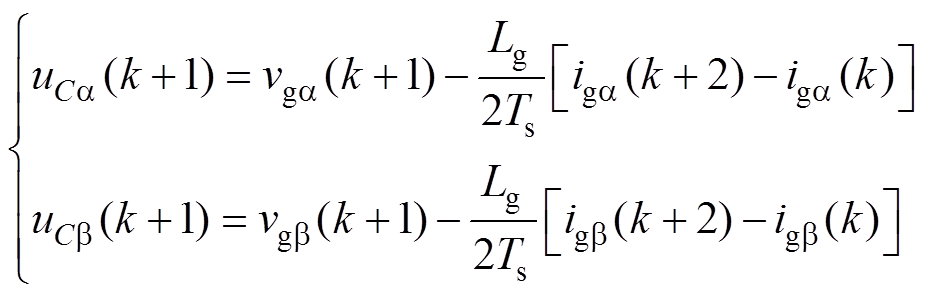 (17)
(17)
由于系统的采样频率远高于电网电压频率,得
 (18)
(18)
根据基尔霍夫电流定律可知,预测时刻的CSR交流侧调制电流为
 (19)
(19)
在ab 坐标系下三相CSR不存在耦合,因此以a 轴为例给出电流内环改进无差拍控制框图如图6所示,图中Gh(s)为零阶保持器(Zero-Order Holder, ZOH),其传递函数表达式为
 (20)
(20)
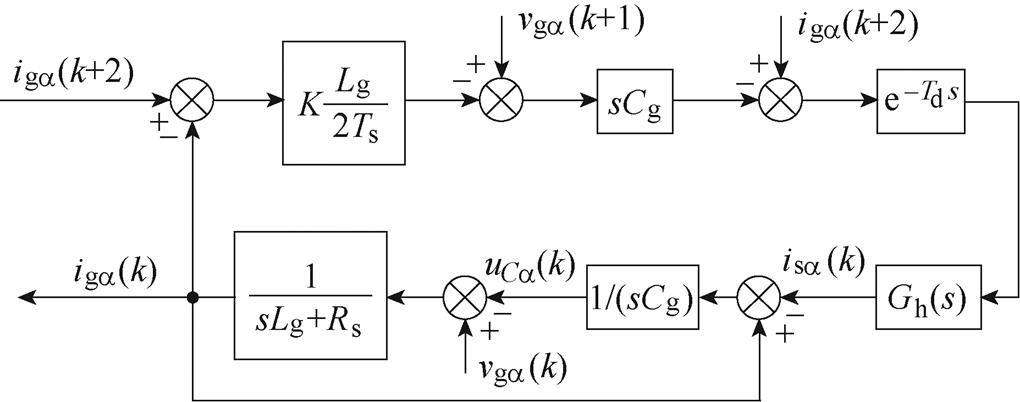
图6 改进无差拍控制框图
Fig.6 Block diagram of improved deadbeat control
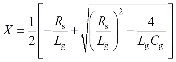
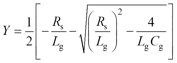
根据图6,忽略电网电动势扰动,可知网侧二阶被控对象传递函数为
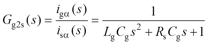 (21)
(21)
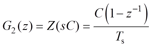
采用零阶保持器对Gg2s(s)进行离散化,其离散域传递函数表达式为
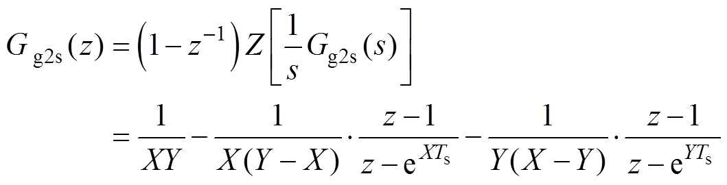 (22)
(22)
其中
由于零阶保持器本身就具有时间滞后特性,加上控制器的控制延时Td,可将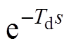 等效为
等效为
 (23)
(23)
同理将其他s域传递函数转换成z域传递函数为
 (24)
(24)
图7所示为改进型DBC控制的离散域模型,可以得到电流内环开环、闭环传递函数分别为
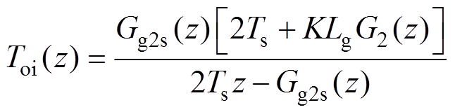 (25)
(25)
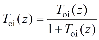 (26)
(26)
式中,K为电感偏差系数, ,即测量网侧滤波电感值与实际滤波电感值之比。
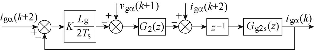
图7 z域下改进DBC框图
Fig.7 Improved DBC block diagram in z domain
若要兼顾电流内环动态响应速度与系统稳定性,则需要合理设计K的取值。电流环闭环零极点分布如图8所示,系统的共轭极点将随着K值增加而向左半单位圆移动,当极点位于左半单位圆内时,系统动态过程性能欠佳。因此,为了确保系统具有良好的动态、静态性能,希望闭环极点位于z平面的右半单位圆内且共轭复数极点阻尼比接近0.707,文中选取K=1.5。
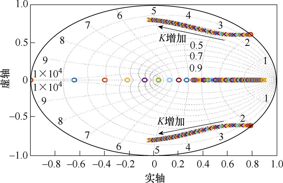
图8 电流环闭环零极点分布
Fig.8 Current loop closed-loop zero pole distribution plot
利用Matlab/Simulink搭建三相CSR仿真系统,通过与传统双闭环控制策略进行对比分析,从而验证所提控制策略的正确性。CSR仿真参数见表1。
表1 CSR仿真参数
Tab.1 Simulation parameters of CSR

参 数数 值 网侧相电压峰值vm/V311 直流侧输出电压uo/V400 开关频率fs/kHz20 网侧电感Lg/mH0.45 网侧电容Cg/mF12 直流侧电感Ldc/mH2.5×2 直流侧电容Cdc/mF100
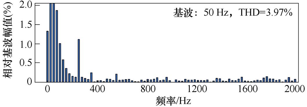
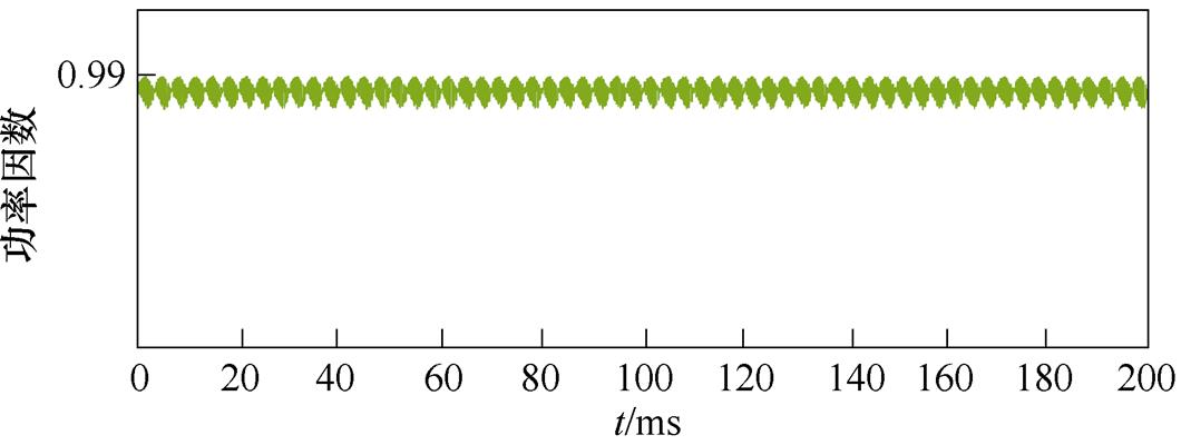
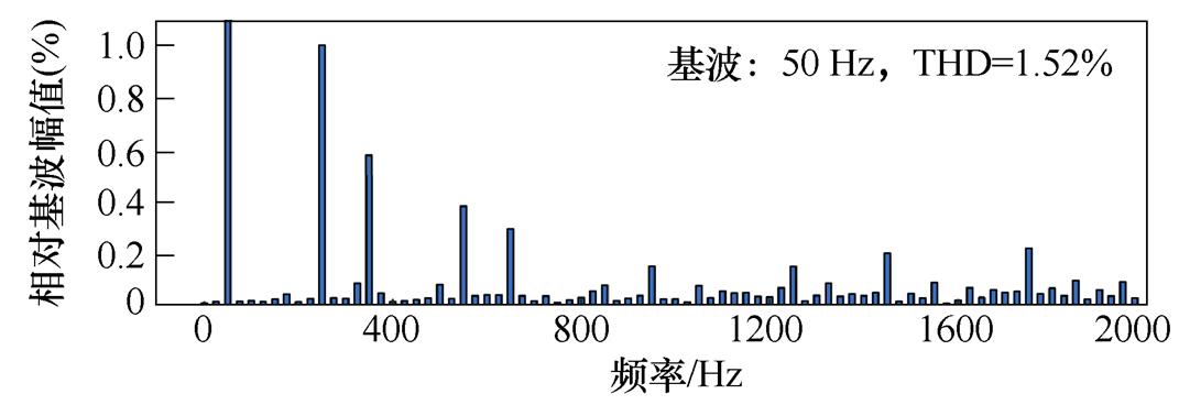
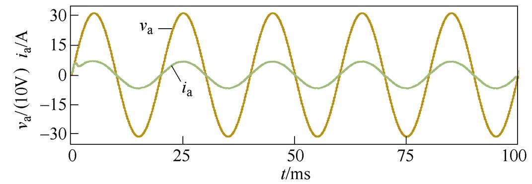
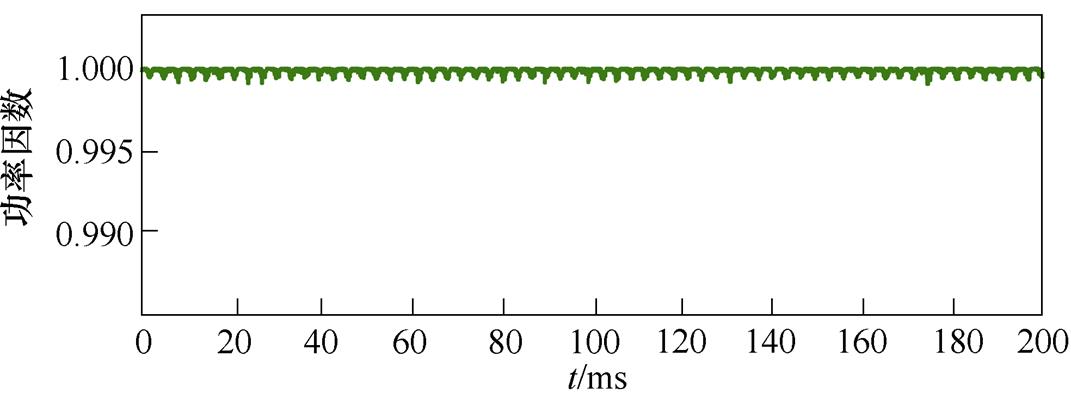
采用传统控制策略时仿真结果如图9所示,三相网侧电流波形质量较差,总谐波畸变率(Total Harmonic Distortion, THD)为3.97 %。文中所提控制方法仿真结果如图10所示,可以看出网侧电流THD仅为1.52 %,波形质量高;网侧电压、电流同相位运行,其功率因数大于0.995。
图11为两种控制策略以50 %负荷带载启动时直流侧输出电压uo波形。可以发现,采用本文所提控制策略时,uo在15 ms左右稳定至给定值,整个响应过程超调量小;而采用传统控制策略调节时间约为55 ms,且存在较大超调。

(a)网侧三相电流
(b)网侧电流的频谱分析

(c)a相电网电压和网侧电流
(d)网侧输入功率因数
图9 传统双闭环控制策略仿真结果
Fig.9 Simulation results of traditional double closed-loop control strategy

(a)网侧三相电流
(b)网侧电流的频谱分析
(c)a相电网电压和网侧电流
(d)网侧输入功率因数
图10 所提控制策略仿真结果
Fig.10 Simulation results of the proposed control strategy
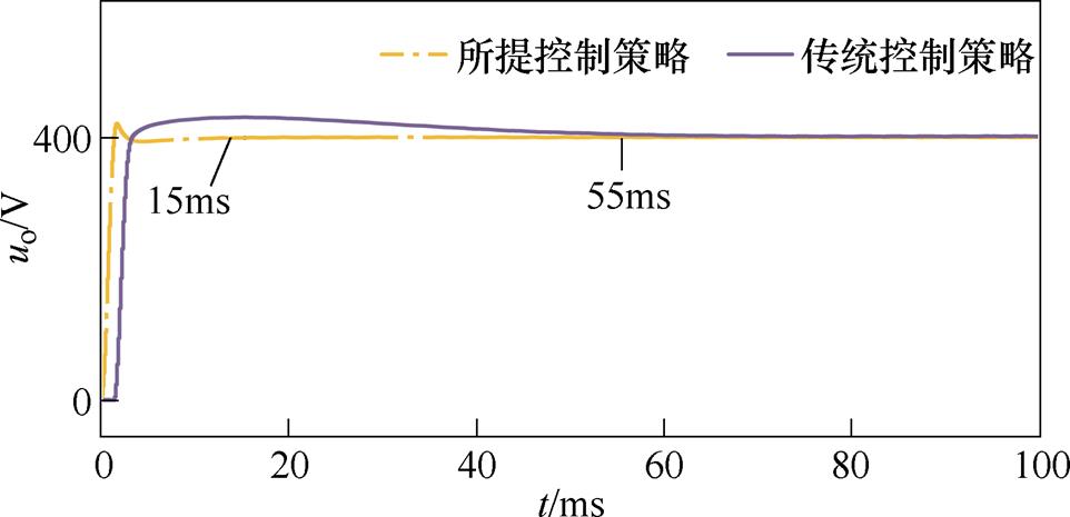
图11 两种控制策略的输出电压
Fig.11 Output voltage for both control strategies
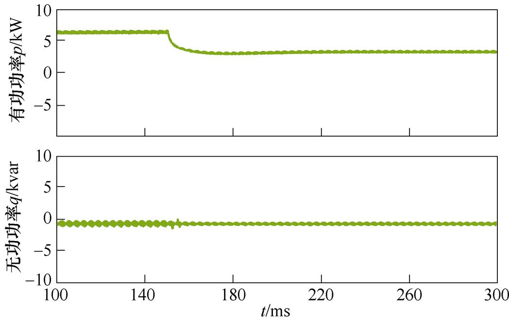
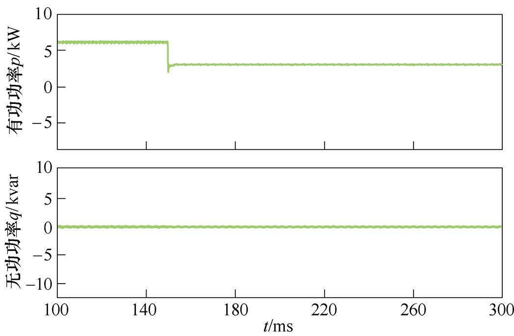
为了验证所提控制策略动态响应能力,图12与图13分别给出了CSR负载由满载减至半载工况下传统控制策略和所提控制策略的仿真结果。在传统控制策略中突减负载时,直流侧输出电压uo超调大于35 V,调节时间约为60 ms,有功功率从满载切换至半载调节时间较长;而本文所提控制方法在突减时,uo能在5 ms内达到新的稳态并实现对给定值的跟踪,整个过程电压波动最大值仅为13 V,网侧电流无明显畸变,有功功率快速到达稳态。
(a)直流侧电压电流与网侧电压电流
(b)有功、无功功率
图12 传统控制策略下满载减至半载仿真结果
Fig.12 Simulation results of full load reduction to half load under traditional control strategy

(a)直流侧电压电流与网侧电压电流
(b)有功、无功功率
图13 所提控制策略下满载减至半载仿真结果
Fig.13 Simulation results of full load reduction to half load under the proposed control strategy
图14与图15给出了CSR负载由半载增加至满载工况下两种控制策略的仿真结果。虽然传统控制策略在突加负载时,网侧电流未产生明显畸变,但直流侧输出电压uo跌落至365 V,经过70 ms左右才恢复至给定值400 V,无功功率也存在一定的波动。然而采用所提控制策略时,当突加负载uo仅跌落14 V,且仅需5 ms便可实现对给定值的跟踪,同时网侧电流在转换过程中波形保持完好。
(a)直流侧电压电流与网侧电压电流
(b)有功、无功功率
图14 传统控制策略下半载增加至满载仿真结果
Fig.14 Simulation results of half load increase to full load under traditional control strategy
(a)直流侧电压电流与网侧电压电流

(b)有功、无功功率
图15 所提控制策略下半载增加至满载仿真结果
Fig.15 Simulation results of half load increase to full load under the proposed control strategy
为了验证所提控制策略的有效性,搭建三相CSR实验样机,如图16所示,实验电气参数同仿真参数一致。三相可编程电源采用Chroma-61830,直流侧电子负载采用ITECH-IT8918,以TMS320F28335+CPLD芯片为控制核心。
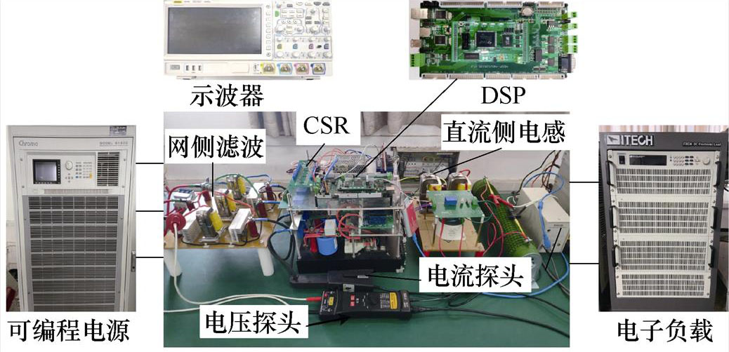
图16 三相CSR实验样机
Fig.16 Three-phase CSR experimental prototype
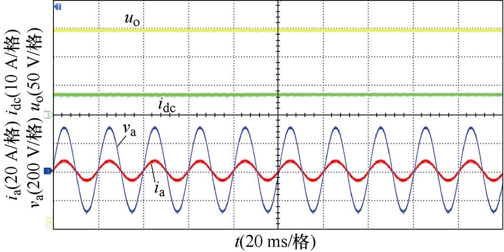
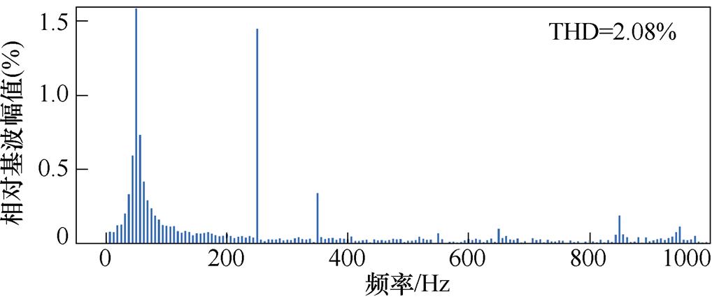
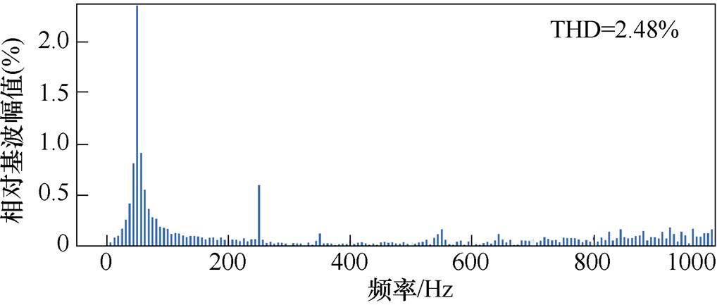
当系统功率为3 kW(半载)和6 kW(满载)时,所提控制策略实验结果如图17所示。可以看到文中所提出的控制策略工作在半载或满载时均能满足三相CSR系统的控制目标:网侧电压电流同相位,网侧电流在半载、满载运行时均呈正弦化,其THD分别为2.08 %和2.48 %;直流侧输出电压uo保持400 V稳定输出,无电压波动。
(a)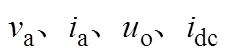 实验波形(3 kW)
(b)网侧电流THD(3 kW)
(c)实验波形(6 kW)
(d)网侧电流THD(6 kW)
图17 所提控制策略实验结果
Fig.17 Experimental results of the proposed control strategy
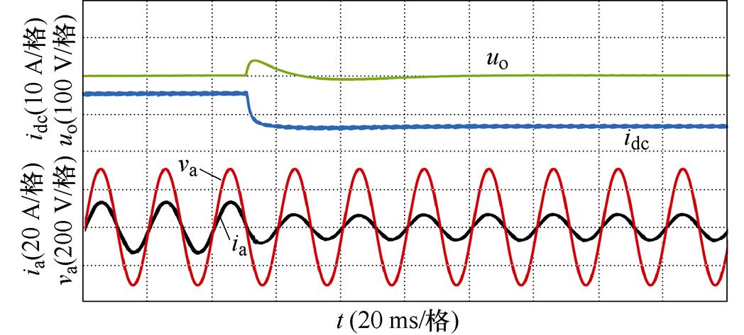
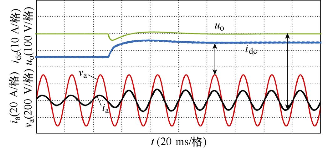
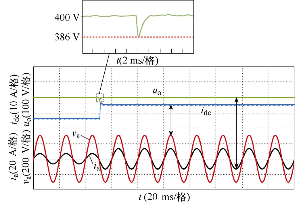
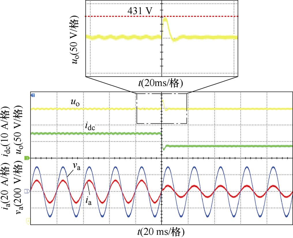
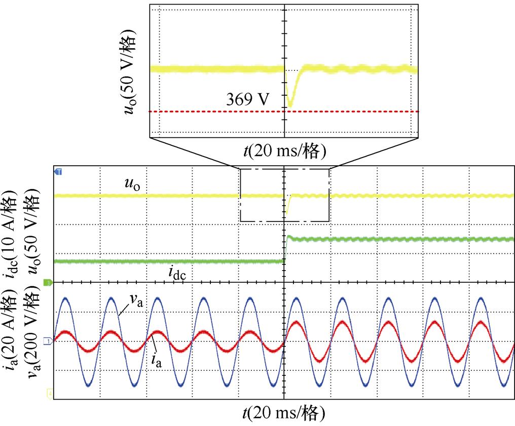
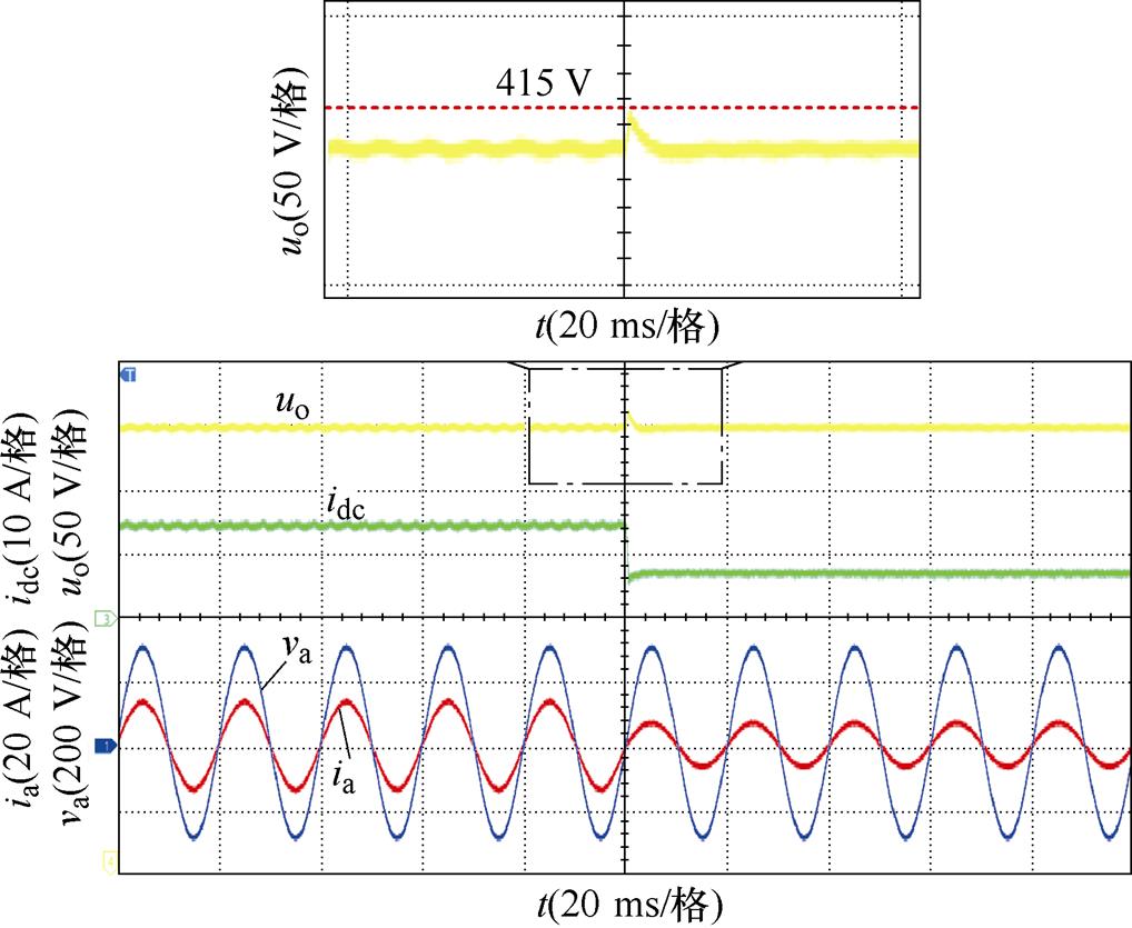
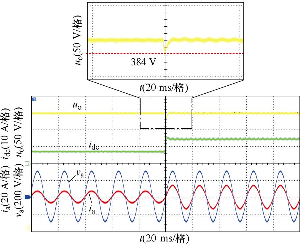
图18、图19分别给出了未加与加入负载功率前馈控制策略两种情况下突减负载、突加负载的实验波形。可以看出,未加负载功率前馈控制在负载突减或突加时,直流侧输出电压uo存在明显波动,其波动幅值已超过30 V,且在突变时刻网侧电流发生畸变;而加入负载功率前馈控制策略时,其网侧电流在负载突变时刻无明显畸变,电流质量保持良好,直流侧电感电流idc能快速达到稳定值,uo能在半个周期内达到稳定状态,波动幅值峰值仅为15 V。
(a)负载突减
(b)负载突增
图18 未加负载功率前馈瞬态响应实验结果
Fig.18 Transient response experimental results of without load power feed-forward
(a)负载突减
(b)负载突增
图19 加入负载功率前馈瞬态响应实验结果
Fig.19 Transient response experimental results of load power feed-forward
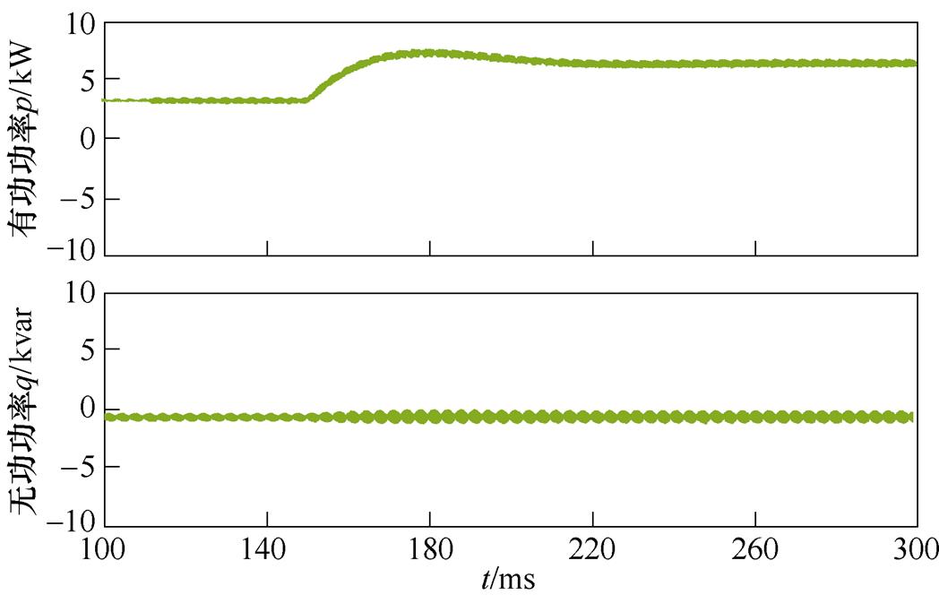
图20为系统在稳态和负载突变工况下的有功、无功功率实验波形。从图20a、图20b可以看出,采用本文所提控制策略时,系统在满载或半载稳态工况下有功功率p、无功功率q独立稳定输出,无功功率q始终近似为零,系统实现单位功率因数运行;图20c、图20d分别给出了负载突变时有功、无功功率变化的波形,可以看出,负载发生突增和突减两种情况下,系统有功、无功功率均能够快速恢复且稳定独立输出,无功功率q始终保持近似为零。
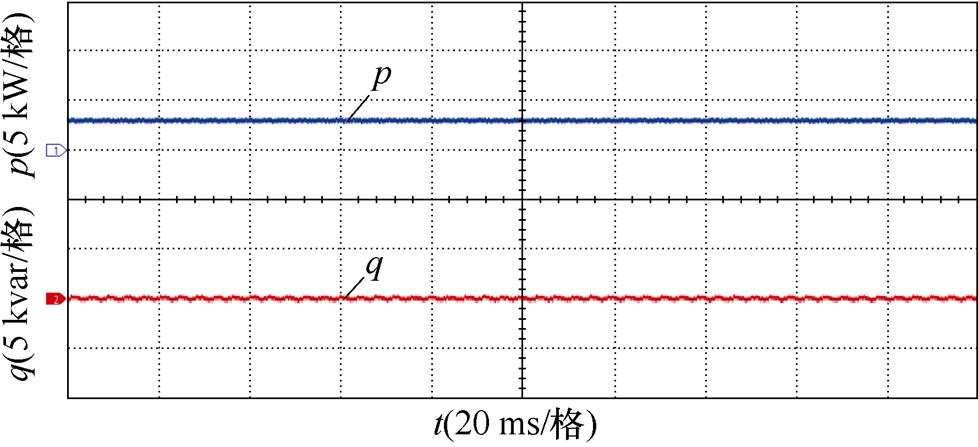
(a)半载时有功、无功功率
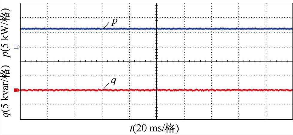
(b)满载时有功、无功功率

(c)负载突增时有功、无功功率
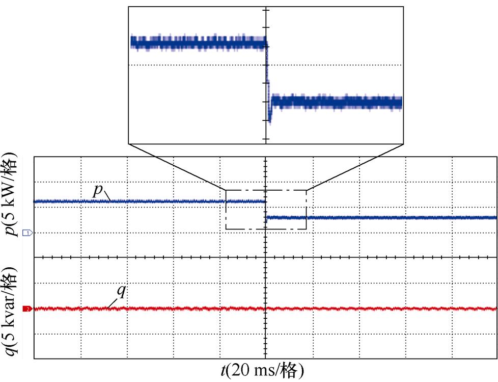
(d)负载突减时有功、无功功率
图20 所提控制策略有功、无功功率实验波形
Fig.20 Active and reactive power experimental waveforms of the proposed control strategy
上述仿真与实验结果表明,本文提出的控制策略能使三相CSR系统稳态性能良好,同时在负载突增、突减等工况下瞬态响应也十分迅速,验证了所提控制策略的正确性。
本文通过分析三相CSR网侧在两相静止坐标系的数学模型,提出了内环采用改进型DBC策略,并利用根轨迹法对电流内环稳定性能进行分析。在环路设计中,通过在外环上加入负载功率前馈等效电流,加快了系统动态响应,解决了负载突变时直流侧电压超调问题。通过与传统双闭环控制策略的仿真进行对比分析与实验验证,得到以下结论:
1)本文所提出的控制策略使系统具有良好的运行性能,其中在不同功率负载下,均能实现单位功率因数运行,电流THD值均低于限制值且输出电压稳定、系统瞬态响应迅速。
2)在外环引入负载功率前馈,能有效改善系统的动态响应。当负载发生突增或突减变化时,均能保证直流侧输出电压快速恢复至给定值,且有效抑制了其过冲和下冲电压。
参考文献
[1] 郭文杰, 林飞, 郑琼林. 三相电压型PWM整流器的级联式非线性PI控制[J]. 中国电机工程学报, 2006, 26(2): 138-142.
Guo Wenjie, Lin Fei, Zheng Qionglin. The cascaded nonlinear PI control for three-phase voltage source PWM rectifier[J]. Proceedings of the CSEE, 2006, 26(2): 138-142.
[2] 李和明, 朱晓荣, 石新春, 等. 电流型PWM整流器的不平衡控制[J]. 电工技术学报, 2010, 25(7): 85- 92.
Li Heming, Zhu Xiaorong, Shi Xinchun, et al. A control scheme of current-source PWM rectifier under unbalanced supply conditions[J]. Transactions of China Electrotechnical Society, 2010, 25(7): 85-92.
[3] 谈龙成, 李耀华, 刘丛伟, 等. 三相电流型PWM整流器的功率因数控制方法[J]. 电工技术学报, 2010, 25(2): 86-93.
Tan Longcheng, Li Yaohua, Liu Congwei, et al. Power factor control method of three phase current source PWM rectifier[J]. Transactions of China Elec- trotechnical Society, 2010, 25(2): 86-93.
[4] 秦海鸿, 张鑫, 朱梓悦, 等. 电流型PWM整流器叠流时间对网侧电流影响及其抑制方法[J]. 电工技术学报, 2016, 31(12): 142-152.
Qin Haihong, Zhang Xin, Zhu Ziyue, et al. Influence of overlap time on the AC grid current of current source PWM rectifier and restraining method[J]. Transactions of China Electrotechnical Society, 2016, 31(12): 142-152.
[5] 郭强, 刘和平, 彭东林, 等. 静止坐标系下电流型PWM整流器电流环控制策略研究及其参数设计[J]. 中国电机工程学报, 2014, 34(15): 2353-2361.
Guo Qiang, Liu Heping, Peng Donglin, et al. A novel control strategy and its parameter design of the current-loop in a stationary frame for current-source PWM rectifiers[J]. Proceedings of the CSEE, 2014, 34(15): 2353-2361.
[6] Zhang Yu, Yi Yongxian, Dong Peimeng, et al. Simplified model and control strategy of three-phase PWM current source rectifiers for DC voltage power supply applications[J]. IEEE Journal of Emerging and Selected Topics in Power Electronics, 2015, 3(4): 1090-1099.
[7] Bai Zhihong, Ruan Xinbo, Zhang Zhongchao. A generic six-step direct PWM (SS-DPWM) scheme for current source converter[J]. IEEE Transactions on Power Electronics, 2010, 25(3): 659-666.
[8] 张强, 吴延飞, 张保顺, 等. 基于三相电流型五电平整流器的空间矢量脉宽调制算法[J]. 电工技术学报, 2020, 35(24): 5134-5141.
Zhang Qiang, Wu Yanfei, Zhang Baoshun, et al. Space vector pulse width modulation strategy based on three-phase five-level current source rectifier[J]. Transactions of China Electrotechnical Society, 2020, 35(24): 5134-5141.
[9] 郭强, 刘和平, 彭东林, 等. 电流型PWM整流器多环控制策略及其参数设计[J]. 中国电机工程学报, 2015, 35(5): 1193-1202.
Guo Qiang, Liu Heping, Peng Donglin, et al. A multi-loop control strategy and parameter design for current-source PWM rectifiers[J]. Proceedings of the CSEE, 2015, 35(5): 1193-1202.
[10] Nussbaumer T, Heldwein M L, Gong Guanghai, et al. Comparison of prediction techniques to compensate time delays caused by digital control of a three-phase Buck-type PWM rectifier system[J]. IEEE Transa- ctions on Industrial Electronics, 2008, 55(2): 791- 799.
[11] Xu Fan, Guo Ben, Xu Zhuxian, et al. Paralleled three-phase current-source rectifiers for high- efficiency power supply applications[J]. IEEE Transa- ctions on Industry Applications, 2015, 51(3): 2388- 2397.
[12] Xu Fan, Guo Ben, Tolbert L M, et al. An all-SiC three-phase Buck rectifier for high-efficiency data center power supplies[J]. IEEE Transactions on Industry Applications, 2013, 49(6): 2662-2673.
[13] 郭强, 周琛力, 李山. 面向电流源型PWM整流器直流侧电压的多环路控制策略[J]. 电工技术学报, 2022, 37(8): 2051-2063.
Guo Qiang, Zhou Chenli, Li Shan. A multiple loops control strategy based on DC link voltage of current source PWM rectifiers[J]. Transactions of China Electrotechnical Society, 2022, 37(8): 2051-2063.
[14] 易永仙, 张宇, 李民英, 等. 电流源型PWM整流器带容性负载的解耦控制方法[J]. 电工技术学报, 2016, 31(4): 95-103.
Yi Yongxian, Zhang Yu, Li Minying, et al. Decoupling control strategy of current-source PWM rectifier with capacitive load[J]. Transactions of China Electrotechnical Society, 2016, 31(4): 95-103.
[15] 姜卫东, 李王敏, 佘阳阳, 等. 直流电容储能反馈和负载功率前馈的PWM整流器控制策略[J]. 电工技术学报, 2015, 30(8): 151-158.
Jiang Weidong, Li Wangmin, She Yangyang, et al. Control strategy for PWM rectifier based on feedback of the energy stored in capacitor and load power feed-forward[J]. Transactions of China Electro- technical Society, 2015, 30(8): 151-158.
[16] 姚绪梁, 王旭, 冯泽文. 改善三相电压型PWM整流器动态性能的研究[J]. 电工技术学报, 2016, 31(增刊1): 169-175.
Yao Xuliang, Wang Xu, Feng Zewen. Research on of improvement of the dynamic ability for PWM rectifier[J]. Transactions of China Electrotechnical Society, 2016, 31(S1): 169-175.
[17] 朱进权, 葛琼璇, 王晓新, 等. 基于自抗扰和负载功率前馈的高速磁悬浮系统PWM整流器控制策略[J]. 电工技术学报, 2021, 36(2): 320-329.
Zhu Jinquan, Ge Qiongxuan, Wang Xiaoxin, et al. Control strategy for PWM rectifier of high-speed maglev based on active disturbance rejection control and load power feed-forward[J]. Transactions of China Electrotechnical Society, 2021, 36(2): 320- 329.
[18] 陈燕东, 罗安, 周乐明, 等. 一种功率前馈的鲁棒预测无差拍并网控制方法[J]. 中国电机工程学报, 2013, 33(36): 62-70, 10.
Chen Yandong, Luo An, Zhou Leming, et al. A robust predictive deadbeat grid-connected control method based on power feed-forward control[J]. Proceedings of the CSEE, 2013, 33(36): 62-70, 10.
[19] Wang Ping, Bi Yuxuan, Gao Fei, et al. An improved deadbeat control method for single-phase PWM rectifiers in charging system for EVs[J]. IEEE Transactions on Vehicular Technology, 2019, 68(10): 9672-9681.
[20] Wang Bo, Dong Zhen, Yu Yong, et al. Static-errorless deadbeat predictive current control using second- order sliding-mode disturbance observer for induction machine drives[J]. IEEE Transactions on Power Electronics, 2018, 33(3): 2395-2403.
[21] 余晨辉, 汪凤翔, 林贵应. 基于在线扰动补偿的三电平PWM整流器级联式无差拍控制策略[J]. 电工技术学报, 2022, 37(4): 954-963.
Yu Chenhui, Wang Fengxiang, Lin Guiying. Cascaded deadbeat control strategy with online disturbance compensation for three-level PWM rectifier[J]. Transactions of China Electrotechnical Society, 2022, 37(4): 954-963.
[22] 曹穆, 许嘉沄, 王珊珊, 等. 不平衡电网下Vienna整流器无差拍预测控制[J]. 电力电子技术, 2022, 56(4): 4-6, 11.
Cao Mu, Xu Jiayun, Wang Shanshan, et al. Deadbeat prediction control of Vienna rectifier under unbalanced power grid[J]. Power Electronics, 2022, 56(4): 4-6, 11.
[23] Feng Yuelu, Konishi Y, Nakaoka M. Deadbeat control scheme for three phase current-fed PFC converter with an optimum PWM strategy[C]//IEEE 1999 International Conference on Power Electronics and Drive Systems, Hong Kong, China, 2002: 485-488.
[24] Nishida K, Konishi Y, Nakaoka M. Novel current control scheme with deadbeat algorithm and adaptive line enhancer for three-phase current-source active power filter[C]//IEEE 2001 Industry Applications Conference, Chicago, IL, USA, 2001: 194-201.
[25] 李山, 马雯, 郭强, 等. 非理想电网条件下PWM整流器优化预测功率控制[J]. 电工技术学报, 2022, 37(18): 4745-4756.
Li Shan, Ma Wen, Guo Qiang, et al. Optimal predictive power control of PWM rectifier under nonideal grid conditions[J]. Transactions of China Electrotechnical Society, 2022, 37(18): 4745-4756.
Improved Deadbeat Control of Current-Source PWM Rectifiers with Load Feed-Forward Compensation
Abstract In a three-phase current source PWM rectifier (CSR), it is necessary to maintain good dynamic performance and supply constant DC output voltage. However, the DC-side voltage and DC-side current double closed-loop control strategy has a slow dynamic response and is prone to an output voltage of DC-side overshoot during load sudden changes. Therefore, this paper proposes an improved control strategy scheme combined with deadbeat predictive current control and load power feedforward compensation.
Firstly, based on the power conservation theory, the power relationship between the input side and the output side of the rectifier is analyzed, and the feedforward current is obtained as the reference current of the inner loop current by feedforward compensation of the DC side power. Secondly, the discrete mathematical model of a three-phase current source PWM rectifier in a two-phase static coordinate system is analyzed. The equation relationship between grid-side current & voltage and AC-side voltage is deduced from the mathematical model according to that the internal loop current is tracked by deadbeat control. However, due to the influence of inductance parameters and control delay, the grid-side current’s control accuracy and waveform quality will be degraded. Accordingly, an improved deadbeat control strategy is adopted. The control algorithm is predicted to the time k+2, and the current at the time k+1 is eliminated by the arithmetic iteration process. It can avoid the deepening of the assumption approximation, make the current at the time k directly related to the current at the time k+2, and simplify the calculation process. The results show that this method improves the control accuracy of grid-side current and reduces the current harmonic content. Finally, the root locus method is used to analyze the stability of the current inner loop.
The comparative simulation and experimental results show that the improved scheme is superior to the conventional scheme in steady and dynamic conditions. Under steady-state conditions, the grid-side voltage and the grid-side current are in the same phase, and the grid-side current is sinusoidal at half-load and full-load operation. Its total harmonic distortion rate (THD) is 2.08% and 2.48%, respectively. The DC-side output voltage keeps stable output at a given value without voltage fluctuations. Under dynamic conditions, the output voltage of the DC side can quickly restore stability, regardless of the sudden increase or decrease of system load, and its fluctuation amplitude is less than 15V.
The following conclusions can be drawn from the simulation and experimental analysis: (1) The proposed control strategy enables the CSR system to have good performance. Under different power loads, unit power factor operation can be realized. The current THD values are below the limits, the output voltage is stable, and the transient system response is rapid. (2) The dynamic response of the system can be effectively improved by introducing load power feedforward into the outer loop. When the load suddenly increases or decreases, the DC output voltage can be quickly restored to a given value, and the overshoot and undershoot voltages are effectively suppressed.
keywords:PWM rectifier, deadbeat control, power feed-forward, predict two beats
DOI: 10.19595/j.cnki.1000-6753.tces.221955
重庆市教委科学技术研究计划重点资助项目(KJQN202001128)。
收稿日期 2022-10-14
改稿日期 2023-01-09
中图分类号:TM461
何黎鹏 男,1998年生,硕士研究生,研究方向为电流源型PWM整流器建模与控制。E-mail: helipeng@stu.cqut.edu.cn
郭 强 男,1984年生,博士,副教授,研究方向为大功率整流器、新型逆变器、汽车电子等。E-mail: guoqiang@cqut.edu.cn(通信作者)
(编辑 陈 诚)