图1 PMSM无位置传感器控制框图
Fig.1 Block diagram of the sensorless control for PMSM
摘要 针对传统正交锁相环(QPLL)应用于永磁同步电机无位置传感器控制中存在的反转失效与加、减速工况下出现显著的转子位置直流偏移误差问题,该文提出一种改进的正交锁相环(IQPLL)。其通过重构鉴相器环节,使得鉴相器的输出与永磁同步电机的转向不再相关,从而解决传统QPLL在电机反转时估算转子位置出现180°偏差的问题。此外,在新型鉴相器结构下,设计前馈环路以补偿加、减速工况下的位置直流偏移误差。并建立了IQPLL的小信号模型,根据系统的频率响应特性给出了IQPLL的参数设计方法。实验结果表明,相对于传统的QPLL,所提出的IQPLL可实现永磁同步电机无位置传感器控制正、反转稳定运行,并有效抑制了加、减速工况下的转子位置直流偏移误差。
关键词:永磁同步电机 正交锁相环 无位置传感器控制
采用无位置传感器控制的永磁同步电机(Permanent Magnet Synchronous Motor, PMSM)驱动系统能以较低成本实现高可靠性、高效率与高功率密度的能量转换[1],成为当前交流电机控制领域的研究热点之一。在零、低速域,PMSM的无位置传感器控制主要采用高频信号注入法[2-4],其向电机定子额外注入高频电压信号,通过检测因转子凸极性导致的高频电流响应进而提取转子位置信息。
而针对于中、高速域,通常采用基频模型法实现PMSM无位置传感器控制,其通过引入观测器以估计反电动势或者磁链信息,进而实现对转子位置和转速信息的提取。由于不依赖转子凸极性与额外的信号注入,基频模型法已在PMSM无位置传感器控制系统中得到广泛应用,其主要包括滑模观测器法[5]、参考模型自适应法[6]、全阶观测器法[7]、扩展卡尔曼滤波器[8]法与其他方法[9-10]。通过采用上述基频模型法观测出反电动势或磁链信息后,可通过正交锁相环(Quadrature Phase Locked Loop, QPLL)以获取电机转速与转子位置信息。相较于反正切函数法[11],QPLL无需微分运算,能够有效抑制噪声扰动,因此QPLL被广泛应用于PMSM的无位置传感器控制中[12-13]。
QPLL包括鉴相器(Phase Detector, PD)、环路滤波器(Loop Filter, LF)和压控振荡器(Voltage- Controlled Oscillator, VCO)三个部分,各部分结构和参数会直接影响QPLL的稳、动态性能。为实现QPLL的性能优化,国内外学者对其做了相应的改进研究。文献[14-16]优化了PD的输入环节,即对反电动势进行归一化处理,以解决传统QPLL带宽随PMSM转速变化而发生改变的问题,简化了QPLL的参数设计。文献[17]构造了基于宽频带同步基频提取滤波器的QPLL,增强了对谐波的抑制能力,提高了系统的动态性能。文献[18]提出了任意相移QPLL,以提升零低速工况下的转速与转子位置估算性能。文献[19]研究了一种双重QPLL,将重构电流信号与估计位置信号进行二次锁相从而实现估算误差的补偿。文献[20]提出一种自适应基准QPLL,可实现对基频相关误差补偿。文献[15]分析了逆变器非线性因素以及转子磁场空间谐波导致传统QPLL所提取的转子位置中存在6次谐波的机理,可通过引入基于复频域带通滤波器[21]、基于递归最小二乘算法的滤波器[22]、自适应陷波器[23]、复系数同步频率滤波器[24]对PD的输入信号进行处理,进而实现估算转子位置中6次谐波的抑制。文献[25]建立了基于正切函数的QPLL结构,解决了传统QPLL在电机反转时观测转子位置与实际转子位置偏差180°的问题。近年来,还发展出一些新型的QPLL技术,如有限状态机预测QPLL[26-27]和基于扩张状态观测器的QPLL[28]。
此外,传统的QPLL为二阶系统,在PMSM加、减速过程中会存在较大的转子位置直流偏移误差[29]。针对此问题,文献[30]通过引入微分前馈补偿量以实现在转速斜坡指令下的转子位置准确估算。文献[31]通过检测q轴电流的微分实现对估算转速的补偿,但微分器的引入使得QPLL抗扰性能有所降低。文献[32]提出了一种前馈QPLL,可以减小加、减速工况下的转子位置估算误差,但是此种方法依赖于PMSM的转子永磁体磁链参数。文献[30-32]中所研究的新型QPLL为三阶系统,理论上可实现对转速斜坡给定的无静差跟踪[29]。文献[33]研究了一种双锁相环技术,也可以克服加减速工况下位置观测误差较大的问题,但为一个四阶系统,复杂度高,其参数设计难度较三阶QPLL有所增加。
纵观上述文献,绝大部分的优化QPLL往往只考虑了单一优化目标,而对于频繁加、减速且需要正、反转的场合,不仅要克服传统QPLL加、减速运行时的转子位置估算误差较大的问题,还需要解决反转工况下观测转子位置与实际转子位置偏差180°的问题。针对上述问题,本文提出了一种改进的QPLL(Improved QPLL, IQPLL),通过优化设计PD环节,使PD环节的输出极性与PMSM旋转方向无关,从而保证PMSM无位置传感器控制下正、反转稳定运行。此外,在改进PD结构基础上设计前馈环路以抑制电机加、减速工况下的位置直流偏移误差,该前馈环路无需微分环节进而能够保持传统QPLL的抗扰性能。建立了改进的QPLL的小信号模型,根据系统的频率响应特性给出了IQPLL的参数设计方法。最后,在630 kW永磁同步电机实验平台上验证了IQPLL的有效性。
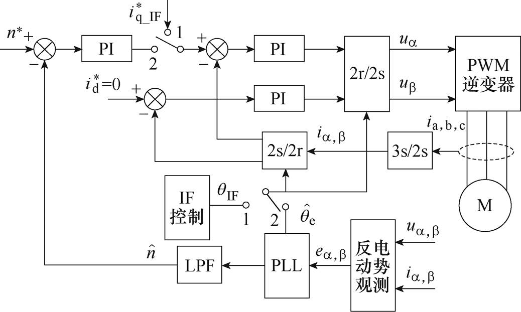
PMSM无位置传感器控制框图如图1所示,对于一些无需在零、低速域调速的场合,基于简单的流频比控制(IF控制)与基于基频模型的无位置传感器控制相配合的方法已成为当前较为成熟的方案,即采用IF控制实现开环起动后再平稳地切换到基于基频模型的无位置传感器控制[34]。在PMSM起动初始时刻,图1中的开关连接到位置1,即使用IF控制器产生的电角度指令qIF进行坐标变换,并将转速环断开,采用IF控制器输出q轴电流指令。当满足所设置的切换条件后,图1中的开关连接到位置2,采用基于反电动势模型的无位置传感器控制器输出的转速和转子位置估算结果进行转速闭环控制[34]。
图1 PMSM无位置传感器控制框图
Fig.1 Block diagram of the sensorless control for PMSM
为确保控制系统鲁棒性与转速控制性能,本文选用二阶自适应超螺旋滑模观测器(Super-Twisting Sliding Mode Observer, STSMO)以实现对PMSM反电动势的观测[35]。
STSMO选取的滑模面为静止坐标系下估算电流与测量电流的差值,其中估算电流满足
 (1)
(1)
式中,Ld、Lq分别为PMSM的d、q轴电感;R为定子电阻; 为a 轴估算电流;
 为b 轴估算电流;
 为电角速度估算值;
 、
、 为a、b 轴反电动势估算值,计算公式分别为
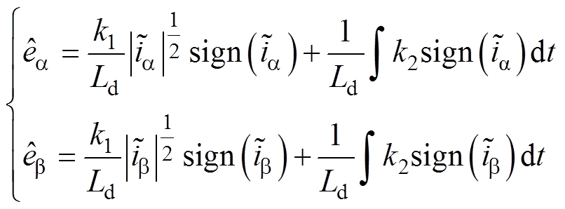 (2)
(2)
式中, 为估算a 轴电流与测量值的差(
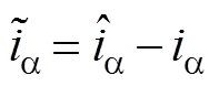 );
); 为估算b 轴电流与测量值的差(
 );sign为符号函数;k1、k2为滑模增益。
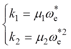
为了确保不同转速下STSMO的稳定性,设计滑模增益的自适应律为
 (3)
(3)
式中, 、
、 为滑模增益的自适应系数;
 为PMSM的给定电角速度。
进一步地,将STSMO观测的反电动势进行归一化[14]并作为如图2所示的传统QPLL的输入,即可获得估算电角速度和估算转子位置 。图2中,
。图2中, 、
、 分别为a 轴和b 轴下的反电动势归一化值[14],kp1、ki1分别为LF环节的比例系数和积分系数。
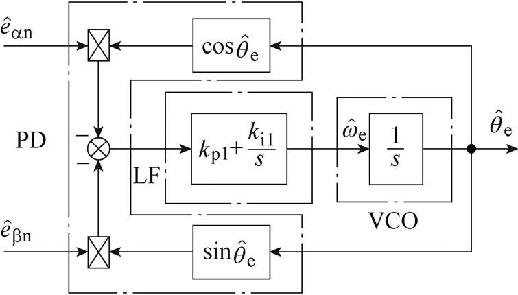
图2 传统正交锁相环结构框图
Fig.2 Block diagram of the conventional QPLL structure
当PMSM反转时,STSMO观测的归一化后的反电动势为
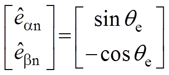 (4)
(4)
式中,qe为实际转子位置。结合图2,PD环节输出的位置误差 为
为

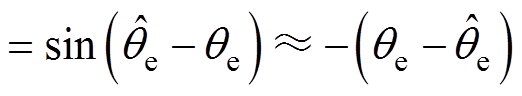 (5)
(5)
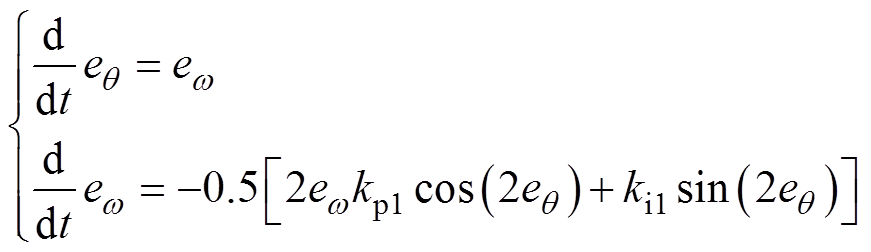
此时PMSM转子位置与电角频率误差的动态微分方程为
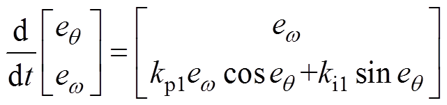 (6)
(6)
式中,eq、ew分别为PMSM转子位置误差和电角频率误差,满足eq = ,
, ,其中
,其中 为实际电角速度。式(6)对应的相轨迹如图3所示,系统的收敛点为(
 , 0)、(
 , 0),而点(0, 0)处呈现发散特征。因此,在PMSM反转工况下,传统QPLL估计的转子位置与实际值之间存在一个180°的稳态误差,从而导致控制失效。
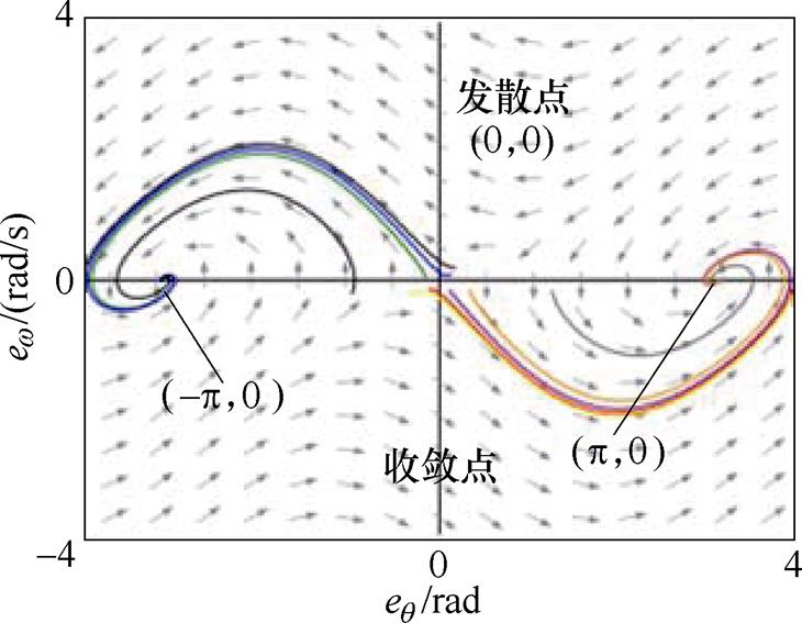
图3 传统QPLL的等效误差相轨迹
Fig.3 Equivalent error phase locus of conventional QPLL
传统QPLL的等效小信号模型如图4所示,转子位置跟踪误差传递函数 为
为
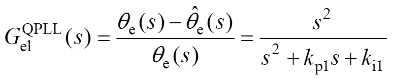 (7)
(7)
式中,kp1和ki1分别为QPLL中的比例系数和积分系数。
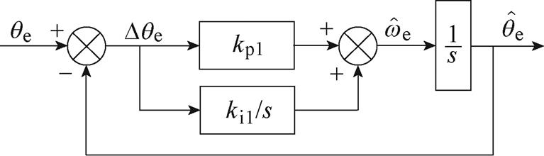
图4 传统QPLL小信号模型
Fig.4 Small signal model of the conventional QPLL
考察式(7)中的转子位置跟踪误差传递函数,在PMSM转速恒定情况下,传统QPLL可实现对PMSM转子位置的无静差跟踪[29]。
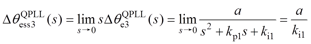
对于加、减速工况,在加、减速起始瞬间,将加速度视为阶跃信号,根据加速度与转子位置之间的数学关系,可得qe的传递函数[30]为
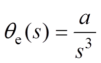 (8)
(8)
式中,a为电角加速度。联立式(7)与式(8)并根据终值定理,可得传统QPLL在PMSM加、减速工况下无法实现对转子位置的无静差跟踪,造成转子位置误差增大的情况,因此传统QPLL在PMSM需要频繁加、减速的场合存在不可忽视的弊端。
 (9)
(9)
针对传统QPLL存在的问题,本文提出了一种新型IQPLL,其控制框图如图5所示,与传统QPLL相比,所提出的IQPLL设计了改进的PD(Improved PD, IPD)模块以克服传统QPLL在PMSM反转工况下失效的问题,引入前馈环路以补偿加、减速工况下的转子位置估算误差。图5中,wL为低通滤波器的截止频率。
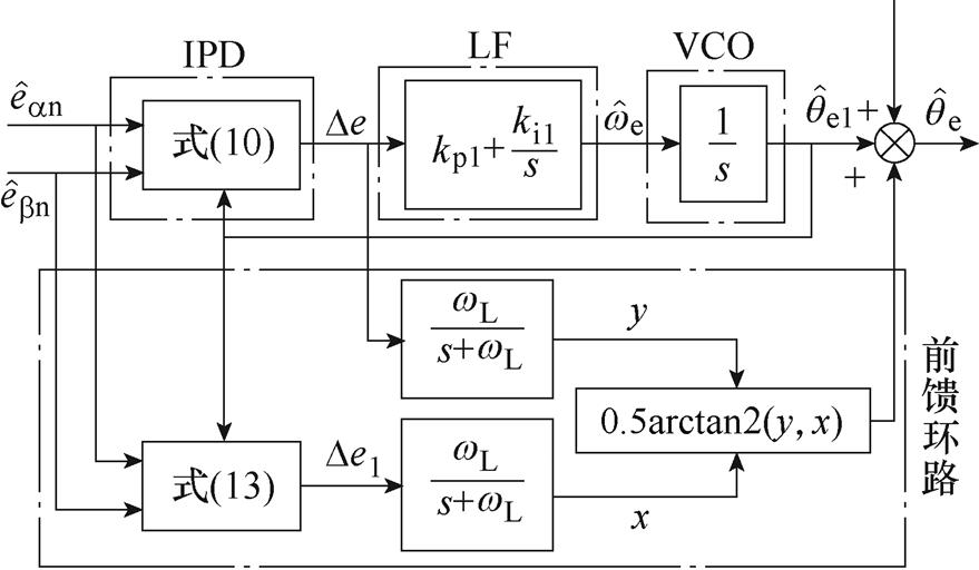
图5 IQPLL控制框图
Fig.5 Block diagram of the IQPLL structure
引入的IPD模块通过改进相位计算方式,使得IPD的输出 表达式为
表达式为
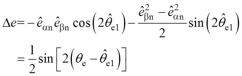 (10)
(10)
式中, 为未经补偿的转子位置估算值。
改进的IPD通过反电动势估算值( )的乘积和二次方运算,使得与PMSM旋转方向无关,且在稳态情况下,可以近似为
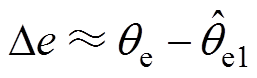 (11)
(11)
在稳态情况下,忽略前馈环路,无论正、反转,PMSM转子位置与电角频率误差的动态微分方程均为
 (12)
(12)
图6所示为IQPLL正、反转工况下的等效误差相轨迹,系统的收敛点为(0, 0)、(, 0)与(, 0),且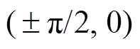 为鞍点。在改进IQPLL中,估算转子位置由估算电角速度的积分叠加前馈分量获取,在IF开环起动到设定转速后,采用IF控制器产生的qIF作为电角速度积分器的初始值,可确保IQPLL投入后的eq 初始值的绝对值小于
 [34],则根据图6可知,eq 与ew 将均能够收敛至0。因此,PMSM在正、反转工况下,IQPLL均能实现对转子位置的追踪。
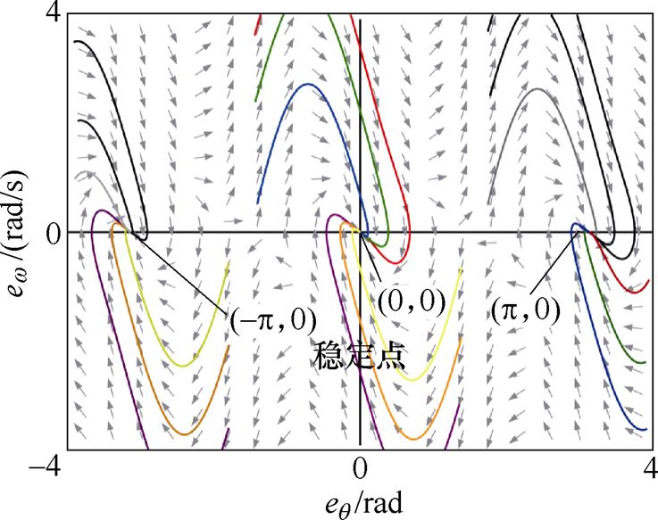
图6 IQPLL等效误差相轨迹
Fig.6 Equivalent error phase locus of the IQPLL
IQPLL的前馈环路首先按照式(13)计算引入的中间变量 ,并将和经过低通滤波器后的反正切值叠加在上获得最终的转子位置估算值。
 (13)
(13)
因此,所提出IQPLL的小信号模型如图7所示。
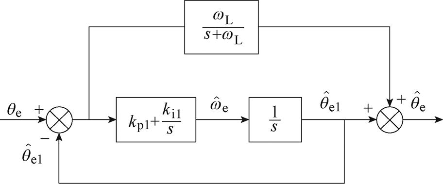
图7 IQPLL小信号模型
Fig.7 Small signal model of the IQPLL
根据图7,可得IQPLL的闭环传递函数 为
为
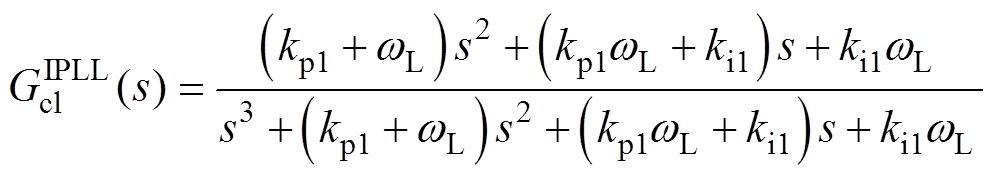 (14)
(14)
为定量分析IQPLL的转子位置跟踪误差,求得转子位置跟踪误差的传递函数 为
为
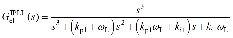 (15)
(15)
对于PMSM加、减速工况,将式(8)中的传递函数与式(15)相乘,并利用终值定理,可得
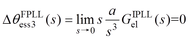 (16)
(16)
因此,对于PMSM加、减速工况,采用IQPLL能够实现对转子位置的无静差跟踪,克服了传统QPLL在PMSM加、减速工况下转子位置跟踪误差大的问题。
由式(14)可反推出IQPLL的开环传递函数 为
为
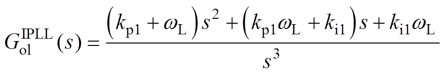 (17)
(17)
因此,IQPLL为一个三型系统,为确保系统的稳定裕度,可将开环传递函数整定[36]为
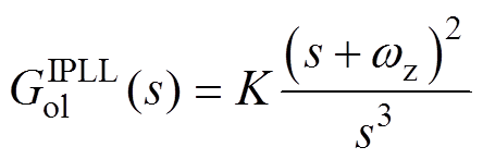 (18)
(18)
式中,K为系统开环增益; 为系统零点。联立式(17)与式(18)可得
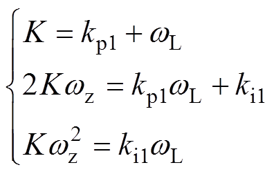 (19)
(19)
对于式(18)中的开环传递函数,其相位裕度PM的表达式为
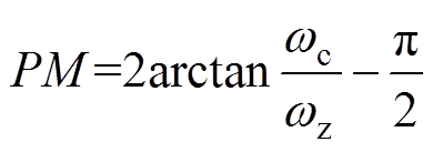 (20)
(20)
式中, 为截止频率,满足
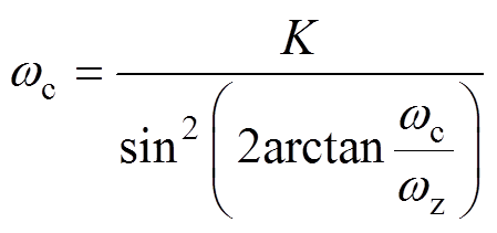 (21)
(21)
联立式(20)和式(21),可得
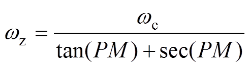 (22)
(22)
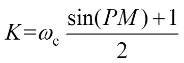 (23)
(23)
由式(19)、式(22)和式(23)可知,只要确定PM和wc即可实现IQPLL的参数整定。
为了保证控制系统的稳定性,PM值一般设置在30°~60°之间,图8所示为固定截止频率(wc= 175 rad/s)下不同PM对应的转子位置误差瞬态响应曲线,其中图8a为转速阶跃工况,图8b为转速斜坡升速工况。当PM较小时,图8a与图8b中的转子位置跟踪的动态性能较好,但振荡时间较长。当PM较大时,转子位置跟踪的动态性能降低,呈现过阻尼特性,收敛时间较长。图9给出不同PM取值下IQPLL的Bode图,PM值越低,闭环传递函数的放大增益越大,IQPLL瞬态响应振荡越剧烈,可得到与图8中相同的结论。为了获得满意的动态性能,推荐PM的选取范围为40°~50°。
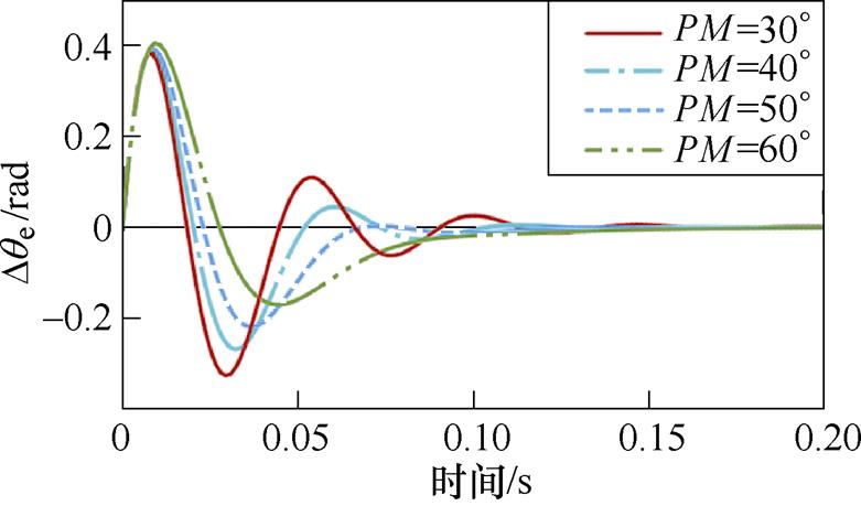
(a)转速阶跃工况
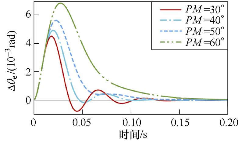
(b)转速斜坡升速工况
图8 不同PM取值下的转子位置误差瞬态响应
Fig.8 Transient response of the rotor position error with various PM
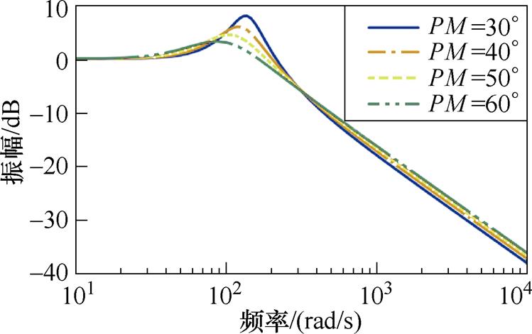
图9 不同PM取值下IQPLL的Bode图
Fig.9 Bode plot of the IQPLL with various PM
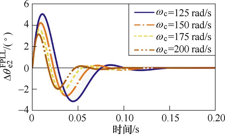
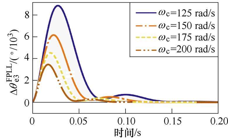
图10所示为固定PM(PM=45°)下不同wc对应的转子位置误差瞬态响应曲线,其中图10a为转速阶跃工况,图10b为转速斜坡升速工况。当wc较小时,图10a与图10b中的转子位置跟踪的动态性能较弱;当wc较大时,转子位置跟踪的动态性能提升,收敛时间减小。图11给出不同wc取值下IQPLL的Bode图,wc取较小值时系统的抗噪能力较强,但动态性能缓慢,随着wc的增加,系统动态性能提升,但对中频段的噪声抑制能力降低。因此,在选取wc时应根据动态性能和噪声抑制能力折衷选取。
(a)转速阶跃工况
(b)转速斜坡升速工况
图10 不同wc取值下的转子位置误差瞬态响应
Fig.10 Transient response of the rotor position error with various wc
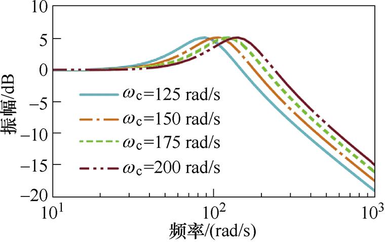
图11 不同wc取值下IQPLL的Bode图
Fig.11 Bode plot of the IQPLL with various wc
与现有的绝大多数改进QPLL[25, 30-31]只优化单一目标不同,本文所研究的IQPLL同时实现了两个目标的优化,不仅解决了传统QPLL反转失效的问题,还抑制了加、减速运行时的转子位置估算误差较大的问题。因此,对于频繁加、减速且需要正、反转的场合,本文所研究的IQPLL具有突出的优势。
表1给出了IQPLL与其他QPLL的性能比较结果,表中功能一为解决反转失效,功能二为抑制加、减速工况下出现的转子位置直流偏移误差。文献[25, 30-31]中的改进QPLL只能实现一种功能,且由于微分环节的存在,使得文献[30-31]中的方法抗扰动能力减弱。文献[33]中的改进QPLL方法能够同时实现功能一和功能二,但是其系统阶数为4,而本文所提出的IQPLL阶数保持为3,其参数设计复杂度较文献[33]中的方法有所降低。
表1 IQPLL与其他QPLL性能比较
Tab.1 Comparison results between the IQPLL and others

方法功能一功能二系统阶数抗扰 传统QPLL无无2强 文献[25]有无2强 文献[30]无有3弱 文献[31]无有3弱 文献[33]有有4强 IQPLL有有3强
为了验证IQPLL的有效性,在如图12所示的630 kW永磁同步电机实验平台上进行无位置传感器控制实验。主控板采用德州仪器型号为TMS320F28377D的数字处理芯片,并配置数模转换电路以实现对控制算法中相关数字量的观测。所采用的永磁同步电机主要参数见表2。实验中,IQPLL的PM和wc分别整定为45°和175 rad/s。为了比较IQPLL与传统QPLL的性能,也对传统QPLL的性能进行了实验验证,其PM和wc整定与IQPLL相同。
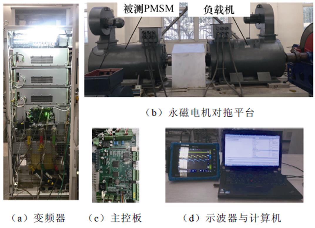
图12 实验平台
Fig.12 Experimental platform
表2 永磁同步电机主要参数
Tab.2 Main parameters of PMSM

参 数数 值 额定电压/V1 140 额定功率/kW630 额定转速/(r/min)750 反电动势/V1 060 定子电阻/W0.004 5 Ld/mH1.56 Lq/mH3.7 极对数6
图13所示为正转加速工况下传统QPLL的实验结果,其中转速由75 r/min上升至750 r/min,加速时间设置为6 s,负载转矩为4 000 N·m。
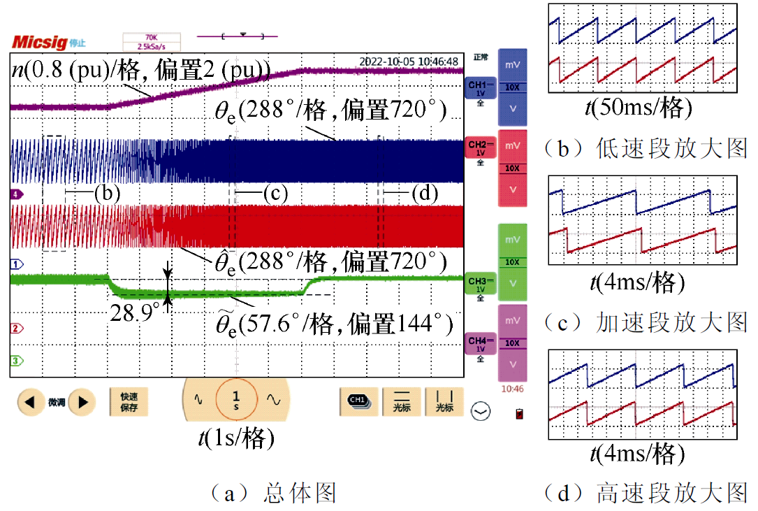
图13 正转加速工况下传统QPLL实验结果
Fig.13 Experimental results of the conventional QPLL in the process of speed up and forward rotation
根据图13a中的转子位置误差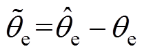 可知,在PMSM匀速运行时,
 接近于0,图13b和图13d中的估算转子位置与实际转子位置接近重合。而在加速阶段,采用传统QPLL时达到28.9°,从图13c中可明显看出,估算的转子位置滞后于实际转子位置。因此,采用传统QPLL时,在正转加速工况下存在较大的转子位置直流偏移误差。
图14所示为正转加速工况下IQPLL的实验结果,其实验工况与图13相同。根据图14a中的波形可知,无论在PMSM匀速运行还是加速运行工况下,均接近于0,图13b~图13d中的估算转子位置与实际转子位置接近重合。因此,IQPLL能够在正转加速工况下抑制转子位置直流偏移误差。
图15所示为正转减速工况下传统QPLL的实验结果,其中转速由750 r/min减小至75 r/min,减速时间设置为6 s,负载转矩为4 000 N·m。根据图15a中的波形可知,在PMSM匀速运行时,接近于0,图15b和图15d中的估算转子位置与实际转子位置接近重合。而在减速阶段,采用传统QPLL时达到28.1°,从图15c中可明显看出,估算的转子位置超前于实际转子位置。因此,采用传统QPLL时,在正转减速工况下存在较大的转子位置直流偏移误差。

图14 正转加速工况下IQPLL实验结果
Fig.14 Experimental results of the IQPLL in the process of speed up and forward rotation
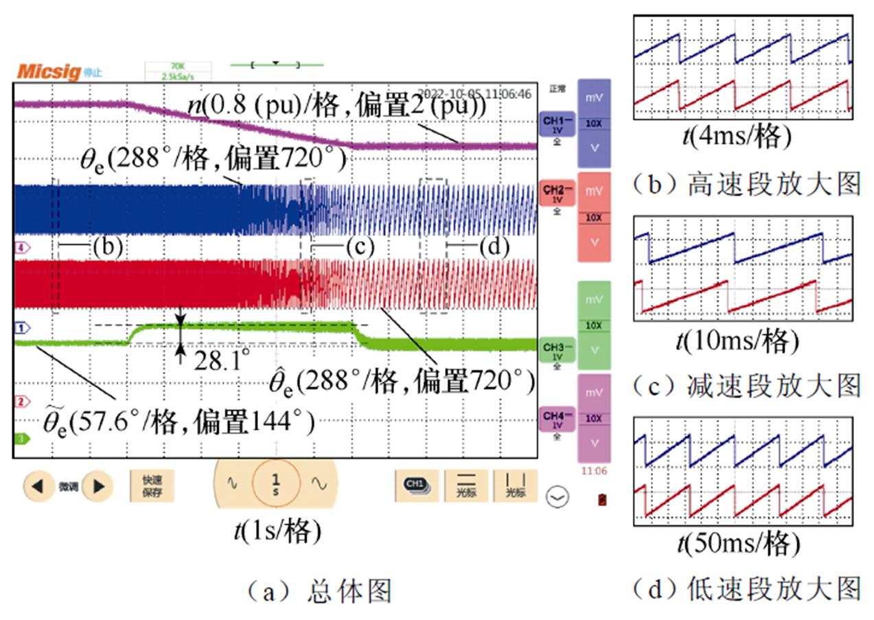
图15 正转减速工况下传统QPLL实验结果
Fig.15 Experimental results of the conventional QPLL in the process of speed down and forward rotation
图16所示为正转减速工况下IQPLL的实验结果,其实验工况与图15相同。根据图16a中的波形可知,无论在PMSM匀速运行还是加速运行工况下,均接近于0,图16b~图16d中的估算转子位置与实际转子位置接近重合。因此,IQPLL能够在正转减速工况下抑制转子位置直流偏移误差。
为了测试传统QPLL在PMSM反转情况下的性能,在IF运行工况下对转子位置进行开环观测,图17给出了观测结果,可见估算转子位置与实际转子位置之间存在180°的相位差,从而导致传统QPLL因失稳无法闭环运行。
图16 正转减速工况下IQPLL实验结果
Fig.16 Experimental results of the IQPLL in the process of speed down and forward rotation

图17 反转工况下传统QPLL的实验结果
Fig.17 Experimental results of the conventional QPLL in the process of reversal rotation
图18所示为反转加速工况下IQPLL的实验结果,其中转速由-75 r/min反向增加至-750 r/min,加速时间设置为6 s,负载转矩为-4 000 N·m。根据图18a中的波形可知,无论在PMSM匀速运行还是加速运行工况下,均接近于0,图18b~图18d中的估算转子位置与实际转子位置接近重合。因此,IQPLL能够在反转加速工况下抑制转子位置直流偏移误差。
图19所示为反转减速工况下IQPLL的实验结果,其中转速由-750 r/min反向减小至-75 r/min,减速时间设置为6 s,负载转矩为-4 000 N·m。根据图19a中的波形可知,无论在PMSM匀速运行还是加速运行工况下,均接近于0,图19b~图19d中的估算转子位置与实际转子位置接近重合。因此,IQPLL能够在反转减速工况下抑制转子位置直流偏移误差。
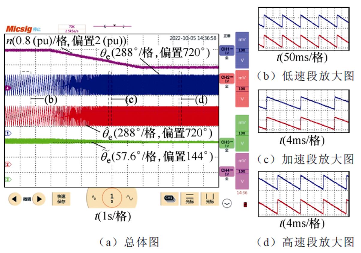
图18 反转加速工况下IQPLL实验结果
Fig.18 Experimental results of the IQPLL in the process of speed up and reversal rotation
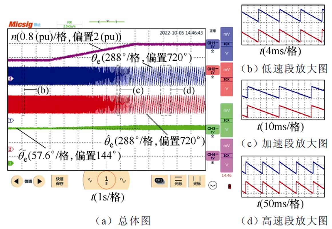
图19 反转减速工况下IQPLL实验结果
Fig.19 Experimental results of the IQPLL in the process of speed down and reversal rotation
以上实验结果表明,所提出的IQPLL能够实现PMSM的反转运行,且能够有效抑制加、减速工况下的转子位置直流偏移误差。
本文分析了PMSM无位置传感器控制中传统QPLL反转失效与加、减速工况下出现转子位置直流偏移误差的原因和机理,提出了一种新型的IQPLL,建立了IQPLL的小信号模型并给出了参数设计方法。通过对所提出的IQPLL进行理论分析以及实验测试,可以得到以下结论:
1)所提出的IQPLL通过重构鉴相器环节,使得鉴相器输出与转速方向无关,有效地克服了传统QPLL在PMSM反转时估算转子位置出现180°偏差的问题。
2)所提出的IQPLL在新型鉴相器结构下引入了前馈环路,将系统校正为三阶系统,有效地抑制了传统QPLL在加、减速工况下出现的转子位置直流偏移误差。
3)与单目标优化改进QPLL不同,所提出的IQPLL同时实现了两个目标的优化,且维持了传统QPLL抗干扰能力强的优点,对于频繁加、减速且需要正、反转的场合,本文所研究的IQPLL具有突出的优势。
参考文献
[1] Xu Wei, Wang Lei, Liu Yi, et al. Improved rotor flux observer for sensorless control of PMSM with adaptive harmonic elimination and phase compen- sation[J]. CES Transactions on Electrical Machines and Systems, 2019, 3(2): 151-159.
[2] 张国强, 项润华, 王高林, 等. 基于静止轴系脉冲信号注入的永磁同步电机无传感器控制策略[J]. 中国电机工程学报, 2021, 41(12): 4297-4306.
Zhang Guoqiang, Xiang Runhua, Wang Gaolin, et al. Pulse signal injection in stationary reference frame for sensorless PMSM drives[J]. Proceedings of the CSEE, 2021, 41(12): 4297-4306.
[3] 赵文祥, 刘桓, 陶涛, 等. 基于虚拟信号和高频脉振信号注入的无位置传感器内置式永磁同步电机MTPA控制[J]. 电工技术学报, 2021, 36(24): 5092- 5100.
Zhao Wenxiang, Liu Huan, Tao Tao, et al. MTPA control of position sensorless built-in permanent magnet synchronous motor based on virtual signal and high frequency pulse signal injection[J]. Transa- ctions of China Electrotechnical Society, 2021, 36(24): 5092-5100.
[4] 曹春堂, 兰志勇, 沈凡享. 永磁同步电机无位置传感器控制系统中初始位置角检测综述[J]. 电气技术, 2020, 21(6): 1-6.
Cao Chuntang, Lan Zhiyong, Shen Fanxiang. Summary of initial position angle detection in sensorless control system of permanent magnet synchronous motor[J]. Electrical Engineering, 2020, 21(6): 1-6.
[5] Sreejith R, Singh B. Sensorless predictive current control of PMSM EV drive using DSOGI-FLL based sliding mode observer[J]. IEEE Transactions on Industrial Electronics, 2021, 68(7): 5537-5547.
[6] 钟臻峰, 金孟加, 沈建新. 基于分段PI调节器的模型参考自适应永磁同步电动机全转速范围无传感器控制[J]. 中国电机工程学报, 2018, 38(4): 1203- 1211, 1297.
Zhong Zhenfeng, Jin Mengjia, Shen Jianxin. Model reference adaptive sensorless control of permanent magnet synchronous motor in full speed range based on piecewise PI regulator[J]. Proceedings of the CSEE, 2018, 38(4): 1203-1211, 1297.
[7] Po-ngam S, Sangwongwanich S. Stability and dynamic performance improvement of adaptive full- order observers for sensorless PMSM drive[J]. IEEE Transactions on Power Electronics, 2012, 27(2): 588-600.
[8] 赵希梅, 武文斌, 朱国昕. 基于扩展卡尔曼滤波器的高速永磁直线同步电机扰动前馈补偿[J]. 电工技术学报, 2018, 33(7): 1516-1522.
Zhao Ximei, Wu Wenbin, Zhu Guoxin. Disturbance feed-forward compensation for high-speed permanent magnet linear synchronous motor based on extended Kalman filter[J]. Transactions of China Electro- technical Society, 2018, 33(7): 1516-1522.
[9] 朱良红, 张国强, 李宇欣, 等. 基于级联扩张观测器的永磁电机无传感器自抗扰控制策略[J]. 电工技术学报, 2022, 37(18): 4614-4624.
Zhu Lianghong, Zhang Guoqiang, Li Yuxin, et al. Sensorless active disturbance rejection control strategy for permanent magnet motor based on cascaded extended observer[J]. Transactions of China Electrotechnical Society, 2022, 37(18): 4614-4624.
[10] 阙鸿杰, 全力, 张丽, 等. 基于自适应滤波器在线解耦的磁场增强型永磁电机无位置传感器控制[J]. 电工技术学报, 2022, 37(2): 344-354.
Que Hongjie, Quan Li, Zhang Li, et al. Sensorless control of flux-intensifying permanent magnet synchronous motor based on adaptive Notch filter online decoupling[J]. Transactions of China Electro- technical Society, 2022, 37(2): 344-354.
[11] 李冉, 赵光宙, 徐绍娟. 基于扩展滑模观测器的永磁同步电动机无传感器控制[J]. 电工技术学报, 2012, 27(3): 79-85.
Li Ran, Zhao Guangzhou, Xu Shaojuan. Sensorless control of permanent magnet synchronous motor based on extended sliding mode observer[J]. Transa- ctions of China Electrotechnical Society, 2012, 27(3): 79-85.
[12] Wang Gaolin, Zhang Guoqiang, Xu Dianguo. Position sensorless control techniques for permanent magnet synchronous machine drives[M]. Singapore: Springer Singapore, 2020.
[13] 袁雷, 胡冰新, 魏克银. 现代永磁同步电机控制原理及MATLAB仿真[M]. 北京: 北京航空航天大学出版社, 2016.
[14] 陈勇, 高玉文, 陈章勇. 一种自适应同步滤波器和正交锁相环相结合的滑模观测器[J]. 电工技术学报, 2018, 33(2): 265-274.
Chen Yong, Gao Yuwen, Chen Zhangyong. A sliding mode observer based on combination of adaptive synchronization filter and quadrature phase locked loop[J]. Transactions of China Electrotechnical Society, 2018, 33(2): 265-274.
[15] 王高林, 李卓敏, 詹瀚林, 等. 考虑逆变器非线性的内置式永磁同步电机转子位置锁相环观测器[J]. 电工技术学报, 2014, 29(3): 172-179.
Wang Gaolin, Li Zhuomin, Zhan Hanlin, et al. Phase- locked-loop rotor position observer for IPMSM considering inverter nonlinearity[J]. Transactions of China Electrotechnical Society, 2014, 29(3): 172- 179.
[16] Wang Gaolin, Li Zhuomin, Zhang Guoqiang, et al. Quadrature PLL-based high-order sliding-mode observer for IPMSM sensorless control with online MTPA control strategy[J]. IEEE Transactions on Energy Conversion, 2013, 28(1): 214-224.
[17] 章春娟, 王慧贞, 刘伟峰, 等. 基于宽频带同步基频提取滤波器的永磁同步电机转子位置与转速估计[J]. 电工技术学报, 2022, 37(4): 882-891.
Zhang Chunjuan, Wang Huizhen, Liu Weifeng, et al. Rotor position and speed estimation of permanent magnet synchronous motor based on wideband syn- chronous fundamental frequency extraction filter[J]. Transactions of China Electrotechnical Society, 2022, 37(4): 882-891.
[18] Wang Yuchen, Bao Xuguang, Hua Wei, et al. Implementation of embedded magnetic encoder for rotor position detection based on arbitrary phase-shift phase-lock loop[J]. IEEE Transactions on Industrial Electronics, 2022, 69(2): 2033-2043.
[19] 顾聪, 王晓琳, 邓智泉. 一种基于双重锁相环的高速永磁同步电机转子位置估计误差全补偿方法[J]. 中国电机工程学报, 2020, 40(3): 962-970.
Gu Cong, Wang Xiaolin, Deng Zhiquan. A rotor position estimated error correction method for high- speed permanent magnet synchronous motor based on dual-phase-locked-loop[J]. Proceedings of the CSEE, 2020, 40(3): 962-970.
[20] 王晓琳, 刘思豪, 顾聪. 基于自适应基准锁相环的高速永磁电机转子位置误差全补偿方法[J]. 电工技术学报, 2021, 36(20): 4308-4317.
Wang Xiaolin, Liu Sihao, Gu Cong. A rotor position error compensation algorithm for high-speed per- manent magnet motor based on phase-locked loop with adaptive reference[J]. Transactions of China Electrotechnical Society, 2021, 36(20): 4308-4317.
[21] Yin Zhonggang, Zhang Yanping, Cao Xinping, et al. Estimated position error suppression using novel PLL for IPMSM sensorless drives based on full-order SMO[J]. IEEE Transactions on Power Electronics, 2022, 37(4): 4463-4474.
[22] Wang Gaolin, Li Tielian, Zhang Guoqiang, et al. Position estimation error reduction using recursive- least-square adaptive filter for model-based sensorless interior permanent-magnet synchronous motor drives[J]. IEEE Transactions on Industrial Electronics, 2014, 61(9): 5115-5125.
[23] Wang Gaolin, Zhan Hanlin, Zhang Guoqiang, et al. Adaptive compensation method of position estimation harmonic error for EMF-based observer in sensorless IPMSM drives[J]. IEEE Transactions on Power Electronics, 2014, 29(6): 3055-3064.
[24] Wu Xuan, Yu Xu, Wu Ting, et al. Complex- coefficient synchronous frequency filter-based posi- tion estimation error reduction for sensorless IPMSM drives[J]. IEEE Transactions on Power Electronics, 2022, 37(12): 15297-15307.
[25] 魏海峰, 韦汉培, 张懿, 等. 基于转子磁链模型的永磁同步电机转子位置估计策略[J]. 电工技术学报, 2018, 33(13): 2963-2971.
Wei Haifeng, Wei Hanpei, Zhang Yi, et al. New rotor position estimation strategy for permanent magnet synchronous motor based on rotor flux model[J]. Transactions of China Electrotechnical Society, 2018, 33(13): 2963-2971.
[26] Sun Xiaodong, Li Teng, Zhu Zhen, et al. Speed sensorless model predictive current control based on finite position set for PMSHM drives[J]. IEEE Transactions on Transportation Electrification, 2021, 7(4): 2743-2752.
[27] Chen Shuo, Ding Wen, Hu Ruiming, et al. Sensorless control of PMSM drives using reduced order quasi resonant-based ESO and newton–raphson method- based PLL[J]. IEEE Transactions on Power Elec- tronics, 2023, 38(1): 229-244.
[28] 王明辉, 徐永向, 邹继斌. 基于ESO-PLL的永磁同步电机无位置传感器控制[J]. 中国电机工程学报, 2022, 42(20): 7599-7607.
Wang Minghui, Xu Yongxiang, Zou Jibin. Sensorless control for permanent magnet synchronous motor based on ESO-PLL[J]. Proceedings of the CSEE, 2022, 42(20): 7599-7607.
[29] Wang Huimin, Yang Yongheng, Ge Xinglai, et al. PLL- and FLL-based speed estimation schemes for speed-sensorless control of induction motor drives: review and new attempts[J]. IEEE Transactions on Power Electronics, 2022, 37(3): 3334-3356.
[30] 左运, 葛兴来, 李松涛, 等. 基于改进型q-PLL的牵引电机无速度传感器控制[J]. 中国电机工程学报, 2021, 41(1): 383-392, 427.
Zuo Yun, Ge Xinglai, Li Songtao, et al. Speed sensorless control of traction motor based on the improved q-PLL[J]. Proceedings of the CSEE, 2021, 41(1): 383-392, 427.
[31] Jiang Feng, Sun Songjun, Liu Anming, et al. Robustness improvement of model-based sensorless SPMSM drivers based on an adaptive extended state observer and an enhanced quadrature PLL[J]. IEEE Transactions on Power Electronics, 2021, 36(4): 4802-4814.
[32] Li Ze, Guo Yuanbo, Xia Jinhui, et al. Modified synchronized SVPWM strategies to reduce CMV for three-phase VSIs at low switching frequency[J]. IEEE Transactions on Industry Applications, 2020, 56(5): 5245-5256.
[33] Liu Gang, Zhang Haifeng, Song Xinda. Position- estimation deviation-suppression technology of PMSM combining phase self-compensation SMO and feed- forward PLL[J]. IEEE Journal of Emerging and Selected Topics in Power Electronics, 2021, 9(1): 335-344.
[34] 刘计龙, 肖飞, 麦志勤, 等. IF控制结合滑模观测器的永磁同步电机无位置传感器复合控制策略[J]. 电工技术学报, 2018, 33(4): 919-929.
Liu Jilong, Xiao Fei, Mai Zhiqin, et al. Hybrid position-sensorless control scheme for PMSM based on combination of IF control and sliding mode observer[J]. Transactions of China Electrotechnical Society, 2018, 33(4): 919-929.
[35] 张懿, 吴嘉欣, 韦汉培, 等. 离散型变增益永磁同步电机超螺旋滑模观测器[J]. 电工技术学报, 2018, 33(21): 4962-4970.
Zhang Yi, Wu Jiaxin, Wei Hanpei, et al. Discrete variable gain super-twisting sliding mode observer for permanent magnet synchronous motor[J]. Transa- ctions of China Electrotechnical Society, 2018, 33(21): 4962-4970.
[36] Golestan S, Monfared M, Freijedo F D, et al. Advantages and challenges of a type-3 PLL[J]. IEEE Transactions on Power Electronics, 2013, 28(11): 4985-4997.
Sensorless Control of Permanent Magnet Synchronous Motor Based on Improved Quadrature Phase-Locked Loop
Abstract APermanent magnet synchronous motor (PMSM) drive system with sensorless control can realize energy conversion with high reliability, high efficiency, and high power density at low cost, which has become a research focus in the current AC motor control field. For the sensorless control of the PMSM in the medium and high-speed region, the speed and rotor position information can be obtained through the quadrature phase-locked loop (QPLL) after the back EMF or flux linkage information is observed by using the fundamental frequency model method.
QPLL includes three parts, i.e., phase detector (PD), loop filter (LF), and voltage-controlled oscillator (VCO). The structure and parameters of each part directly affect the stability and dynamic performance of QPLL. To optimize the performance of QPLL, scholars have made corresponding improvements. However, most improved QPLLs usually only consider a single optimization objective. For the occasion where frequent acceleration and deceleration and forward and reverse rotation are required, it is necessary to overcome the problem that large estimation error of rotor position appears during acceleration and deceleration operation. In addition, a 180 degrees deviation between the observed rotor position and the actual rotor position under reverse rotation conditions needs to be solved.
The reverse failure and significant DC offset error appear in the rotor position under acceleration and deceleration conditions when conventional quadrature phase-locked loop (QPLL) is applied to sensorless control of the PMSM. Therefore, the deterioration mechanism of the conventional QPLL under reverse rotation and acceleration/deceleration conditions is analyzed, and an improved quadrature phase-locked loop (IQPLL) is proposed. By reconstructing the phase detector, the output of the phase detector is independent of the rotation direction of the PMSM, thus solving the 180-degree deviation problem in estimating the rotor position when the motor reverses. In addition, under the new phase detector, a feedforward loop is designed to compensate for the DC offset error in the rotor position under acceleration and deceleration conditions. The small signal model of the new IQPLL is established, and the parameter design method of IQPLL is given according to the frequency response characteristics of the system.
The experimental results in a 630 kW PMSM platform show that the proposed IQPLL, compared with the conventional QPLL, can realize the forward and reverse control of the PMSM, and effectively suppress DC offset error in the rotor position under acceleration and deceleration conditions.
Unlike most existing improved QPLLs that only optimize a single objective, the proposed IQPLL simultaneously optimizes two objectives. Thus, the conventional QPLL’s inversion failure can be solved, and the large rotor position estimation error during acceleration and deceleration operation can be suppressed. Accordingly, the IQPLL studied in this paper has outstanding advantages for the occasions where acceleration and deceleration are frequent and forward and reverse rotation are required.
keywords:Permanent magnet synchronous motor (PMSM), quadrature phase-locked loop, sensorless control
中图分类号:TM464
DOI: 10.19595/j.cnki.1000-6753.tces.221926
国家自然科学基金(52007190)和江苏省自然科学基金(BK20200652)资助项目。
收稿日期 2022-10-09
改稿日期 2022-11-07
吴 翔 男,1990年生,博士,讲师,研究方向为电力电子与电力传动。E-mail: cumtwuxiang@cumt.edu.cn
张 晓 男,1974年生,教授,研究方向为大功率电力传动。E-mail: zhangxiao@cumt.edu.cn(通信作者)
(编辑 崔文静)