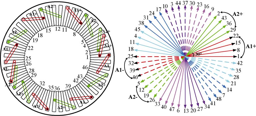
图1 绕组分布和槽电动势星形图
Fig.1 Winding distributions and slot electric potential star diagram
摘要 传统永磁辅助同步磁阻电机(PMaSynRM)无法充分利用永磁转矩和磁阻转矩,该文提出一种新型不对称交替极永磁辅助同步磁阻电机(ACP-PMaSynRM)。基于永磁磁链相移原理,将交替极永磁阵列、不对称磁极和磁障相结合,实现永磁转矩和磁阻转矩的最大值在相同电流相位下叠加,不但提高了永磁转矩和磁阻转矩的利用率,增强了电机输出转矩能力,而且减少了永磁体用量。采用有限元法对比分析了传统和新型ACP-PMaSynRM的电磁性能,验证了所提电机拓扑的可行性。最后,制造了一台48槽14极样机并对其进行了实验验证。
关键词:永磁辅助同步磁阻电机 交替极 磁链相移 最大转矩
永磁同步电机具有高效率、高转矩密度等优点,在新能源汽车、航空航天等领域得到广泛应用。但随着永磁材料价格的不断上涨,高效率、高转矩密度且少永磁体用量的永磁电机已成为研究热点[1-4]。正如永磁辅助同步磁阻电机(Permanent Magnetassisted Synchronous Reluctance Motor, PMaSynRM)不仅可减少永磁体用量,而且结合了永磁同步电机和同步磁阻电机的优点,能获得与传统永磁同步电机相近的性能。目前,PMaSynRM可应用于新能源汽车、压缩机、机器人等领域[5-7]。
PMaSynRM转子拓扑已被广泛研究,如棒状[8]、V形[9]、三角形[10]、双V形[11]以及多层磁障转子结构[12-13]。尽管这些具有对称转子结构的PMaSynRM在不同电流角下能实现最大永磁转矩或磁阻转矩,但所合成的最大转矩中永磁和磁阻转矩无法同时达到最大值[14-17]。因此,PMaSynRM存在永磁和磁阻转矩利用率小、永磁体利用率低等问题。
为解决该问题,文献[18-19]提出一种由同步磁阻电机和内置式永磁同步电机两子电机组成的模块化PMaSynRM,通过改变这两子电机的相对位置,实现同步磁阻电机产生的磁阻转矩和永磁同步电机产生的永磁转矩在同一电流相位下达到最大值,但机械结构较复杂。文献[20]提出了一种混合式PMaSynRM,永磁体轴向安装,以特定的装配角将两种独立且对称的转子轴向集成在一起,实现了永磁和磁阻转矩的充分利用,但各部分转子需紧密配合。文献[21-22]中提出了一种具有混合磁极配置的转子拓扑,即交替使用不对称内置式永磁体和对称V形永磁体。与传统V形永磁电机相比,基于混合磁极的永磁电机显著提高了输出转矩并且降低了转矩脉动。文献[23]提出了基于径向和周向分布的混合型不对称转子拓扑,采用辐条形和棒形永磁体,提高了永磁和磁阻转矩的利用率。文献[24]在U形磁障中嵌入不对称永磁体,以实现磁场偏置,确保永磁转矩和磁阻转矩在相同的电流相位下达到最大值。文献[25]提出一种基于转子结构不对称V形永磁阵列的PMaSynRM,该结构通过改变永磁体和磁障分布,减小d轴和q轴间的机械角,实现在同一电流相位下永磁和磁阻转矩达到最大值,进而提升电机输出转矩能力,但增加了转矩脉动。文献[26]利用不对称转子结构提高永磁和磁阻转矩利用率,并比较了基于不对称转子与传统转子的永磁电机输出转矩能力,论证了在不对称转子中采用磁链偏移可提高转矩密度。可见,在PMaSynRM中引入不对称转子拓扑,采用磁链相移原理使最大永磁转矩和最大磁阻转矩的电流角逼近,能提高永磁转矩和磁阻转矩利用率,从而提升电机输出转矩能力。
因此,针对电推进系统对高转矩密度、低转矩脉动和低成本永磁电机的需求,本文提出一种新的不对称交替极永磁辅助同步磁阻电机(Asymmetric Consequent Pole Permanent Magnet assisted Syn- chronous Reluctance Motor, ACP-PMaSynRM)。基于永磁磁链相移原理,分析比较了永磁体不同放置形式下永磁磁链相移角和输出转矩能力之间的关系。在此基础上,进行优化以实现最大永磁转矩所对应的电流相位与最大磁阻转矩所对应的电流相位完全重合。通过有限元法对传统PMaSynRM和所提出的ACP-PMaSynRM的电磁性能进行对比分析。最后,加工了一台样机并进行了相关实验验证。
图1为PMaSynRM的定子结构和绕组分布,电机采用48槽14极双三相双层分布式绕组。双三相绕组由两套三相绕组组成,第二套绕组A2在第一套绕组A1相位基础上相移30°。图2a所示为交替极PMaSynRM(模型Ⅰ)的转子拓扑[27],永磁体与铁心交替分布在转子圆周上;图2b为所提出的ACP-PMaSynRM(模型Ⅱ)转子拓扑,转子第二层和第三层磁障不对称,且第三层磁障为“一+U”形,不对称交替极阵列永磁体嵌在第二层和第三层磁障中。模型Ⅰ作为模型Ⅱ的对比,除了永磁体用量和其在转子上安装位置不同外,其余均相同,基本参数见表1。

图1 绕组分布和槽电动势星形图
Fig.1 Winding distributions and slot electric potential star diagram
图3为ACP-PMaSynRM永磁磁链相移原理。图中,ypm为永磁磁链,qe为电角度。由于模型Ⅱ采用不对称转子结构,且第二和第三层右侧磁障向左偏移l 角度,永磁磁链最大值从传统d轴相移g 角到d1轴。永磁磁链相移改变了最大永磁磁链所对应的电流相位,进而可实现永磁转矩和磁阻转矩最大值所对应电流相位的逼近,以提高永磁转矩和磁阻转矩的利用率。图4为模型Ⅰ和Ⅱ的空载磁力线分布。可见,当转子采用模型Ⅰ拓扑时,永磁磁力线均从A和B两处经过;当转子采用模型Ⅱ拓扑时,经过B处的永磁磁力线明显减少。因此,永磁磁链最大值所处位置发生了相移。
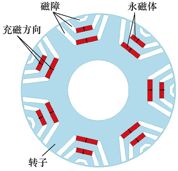
(a)模型Ⅰ
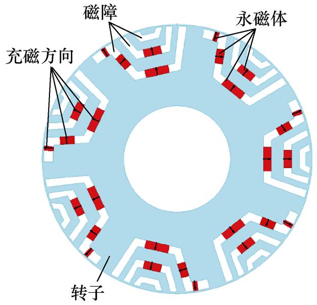
(b)模型Ⅱ
图2 PMaSynRM转子拓扑
Fig.2 Topologies of PMaSynRM rotors
表1 模型Ⅰ和Ⅱ基本参数
Tab.1 Basic parameters of the model Ⅰ and Ⅱ
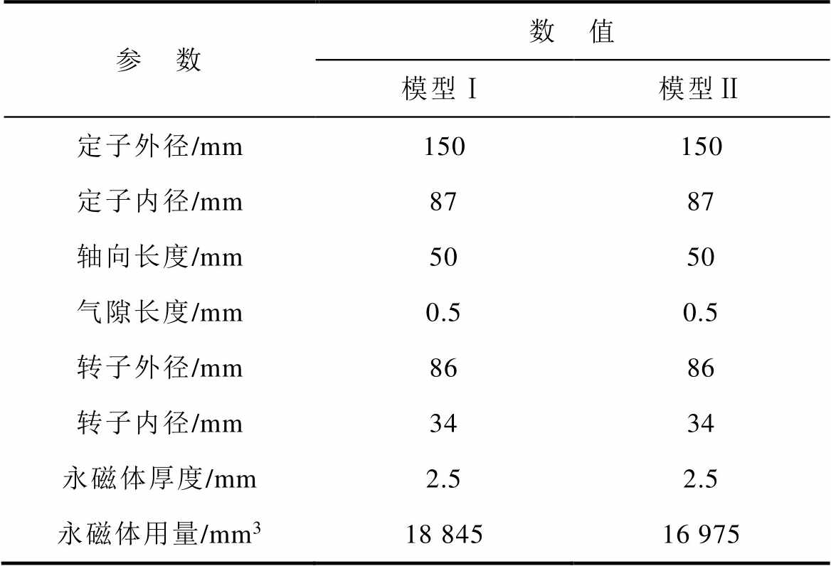
参 数数 值 模型Ⅰ模型Ⅱ 定子外径/mm150150 定子内径/mm8787 轴向长度/mm5050 气隙长度/mm0.50.5 转子外径/mm8686 转子内径/mm3434 永磁体厚度/mm2.52.5 永磁体用量/mm318 84516 975
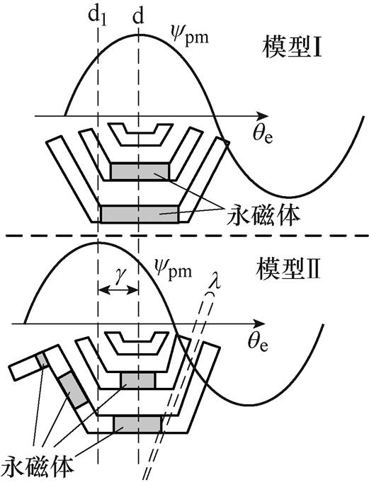
图3 永磁磁链相移原理
Fig.3 Principle of permanent-magnet flux linkage phase shifting
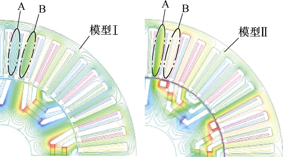
图4 空载磁力线分布
Fig.4 No-load magnetic field Distributions
图5为PMaSynRM模型Ⅰ和Ⅱ中各参数在dq坐标系上的矢量图。图中,is为电枢电流矢量;us为相电压矢量;j 为功率因数角;ys为合成磁链矢量;y0为电枢电流产生的磁链矢量;ypm为永磁磁链矢量;Ld, Lq、id, iq分别为d、q坐标系上的电感和电流;g 为d1与d轴夹角;b1为is与q轴的夹角,b2为is与q1轴的夹角。可见,永磁磁链最大值从传统的d轴相移g 到d1轴,形成新的d1q1坐标系,由此推导出模型Ⅱ在d1q1坐标系上的电磁转矩为
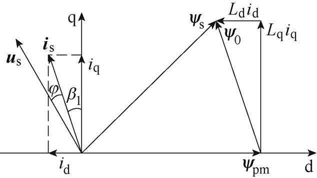
(a)模型Ⅰ
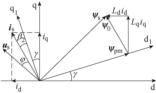
(b)模型Ⅱ
图5 PmaSynRM矢量图
Fig.5 Vector graph of PMaSynRM

 (1)
(1)
式中,Te为电磁转矩;p为极对数;Tpm和Tr分别为永磁转矩和磁阻转矩。
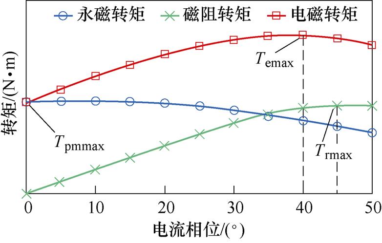
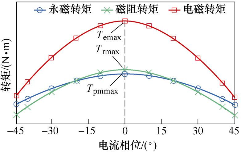
由式(1)可知,当g =p/4、b2=0时,Tpm和Tr同时达到最大值。图6为模型Ⅰ和Ⅱ的转矩特性。可见,模型Ⅰ中永磁转矩最大值与磁阻转矩最大值对应的电流相位相差45°,且两电流相位均不是最大输出转矩所对应的电流相位。因此,模型Ⅰ中永磁转矩和磁阻转矩均未能得到充分利用。模型Ⅱ中各转矩最大值所对应的电流相位相同,永磁转矩与磁阻转矩均得到充分利用。因此,改变转子磁障和永磁体放置位置可实现永磁磁链相移,确保最大永磁转矩和最大磁阻转矩所对应的电流相位相同,从而实现永磁转矩和磁阻转矩的充分利用,增强电机输出转矩能力。
(a)模型Ⅰ
(b)模型Ⅱ
图6 模型Ⅰ与模型Ⅱ的理想转矩特性
Fig.6 Ideal torque characteristics of Model Ⅰ and Model Ⅱ
基于有限元法,对模型Ⅱ的永磁体结构参数进行优化仿真分析,其结构参数如图7所示。在优化设计中,变量的选择对优化结果影响较大。为避免盲目地选择优化变量而增大计算量,把次要变量按常数处理。通过对比各个变量对电流角和转矩的影响程度,在PM3与PM4永磁体用量之和不变的情况下,在PM3中心位置到圆心的距离r3、PM4中心位置到圆心的距离r4以及二者厚度h不变的条件下,选择PM3宽度b1与PM4宽度b2作为模型Ⅱ分析的变量,能清晰地反映电流相位和电磁转矩的变化趋势。b1与b2之间的约束方程为
 (2)
(2)
式中,l为电机的轴向长度;V3+4为PM3与PM4体积之和。根据模型Ⅱ的初步设计,确定b1和b2的范围分别为:4.45 mm≤b1≤4.7 mm,1.35 mm≤b2≤1.55 mm。参数优化如图8所示。由图8可知,随着b1和b2不断增大,电流相位先减小后增大,磁阻转矩最大值与永磁转矩最大值之和先增大后减小。当b1=4.62 mm、b2=1.49 mm时,磁阻转矩最大值与永磁转矩最大值所对应的电流相位之差为0°,永磁转矩最大值与磁阻转矩最大值之和达到11.61 N·m。图9为模型Ⅱ优化前后的转矩特性,优化后的永磁和磁阻转矩在同一电流相位处达到最大值,实现了永磁和磁阻转矩的充分利用。图10为模型Ⅱ转子永磁体结构参数优化前后的转矩波形。可见,参数优化后模型Ⅱ输出转矩提升了11.5%,转矩脉动降低了68.3%。模型Ⅱ优化前后的主要参数见表2。
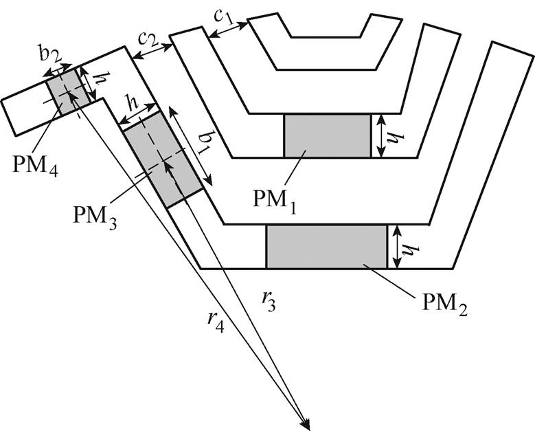
图7 转子永磁体结构参数
Fig.7 Parameters of PMs in the rotor
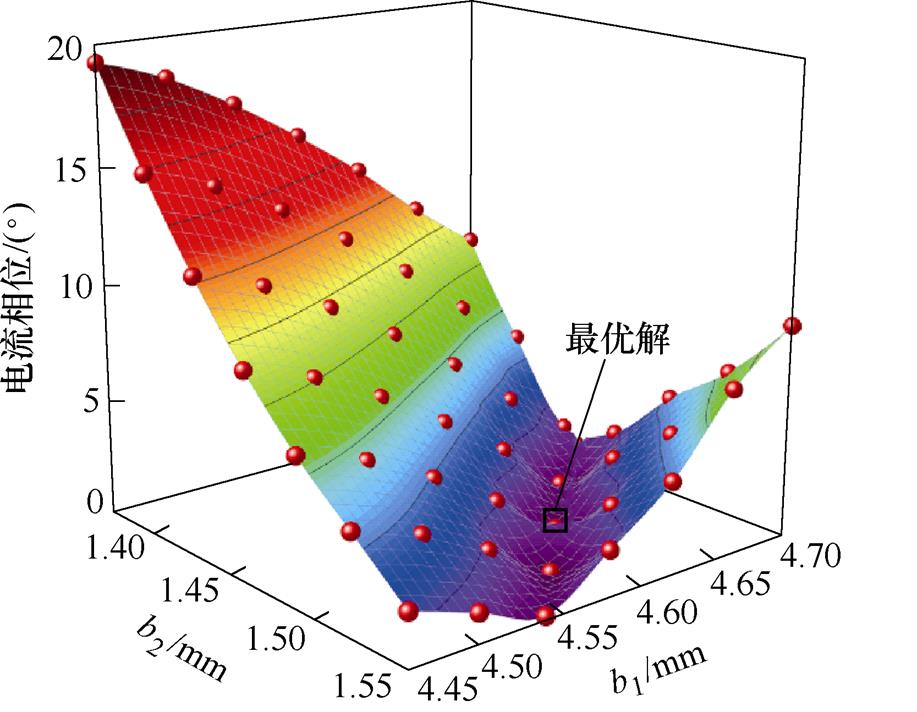
(a)磁阻转矩最大值与永磁转矩最大值所对应的电流相位之差
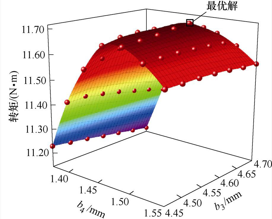
(b)磁阻转矩最大值与永磁转矩最大值之和
图8 参数优化
Fig.8 Optimization of parameters
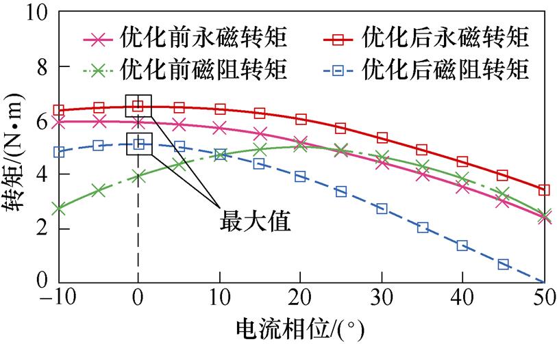
图9 模型Ⅱ优化前后的转矩特性
Fig.9 Torque characteristics of model Ⅱ before and after optimization
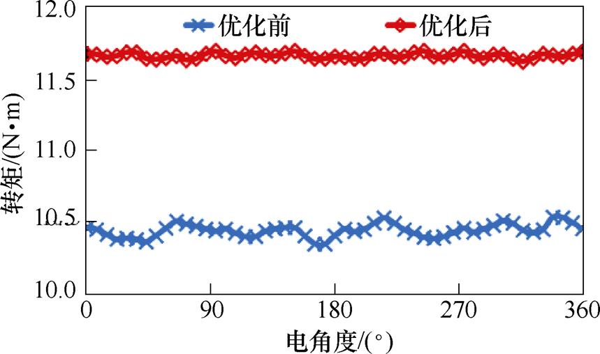
图10 模型Ⅱ优化前后的输出转矩
Fig.10 Output torque of model Ⅱ before and after optimization
基于有限元分析,从磁场分布、空载反电动势以及转矩特性等角度对PMaSynRM模型Ⅰ和Ⅱ进行对比分析。模型Ⅰ与Ⅱ的永磁体用量分别为18 845 mm3和16 975 mm3。与模型Ⅰ相比,模型Ⅱ的永磁体用量减少9.9%。
表2 模型Ⅱ主要优化参数
Tab.2 Optimization parameters of model Ⅱ
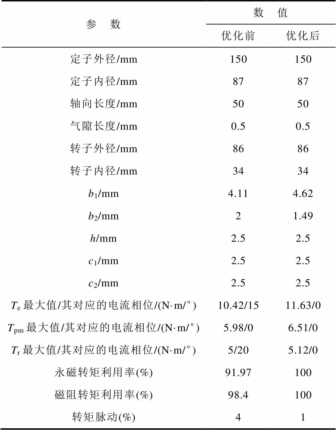
参 数数 值 优化前优化后 定子外径/mm150150 定子内径/mm8787 轴向长度/mm5050 气隙长度/mm0.50.5 转子外径/mm8686 转子内径/mm3434 b1/mm4.114.62 b2/mm21.49 h/mm2.52.5 c1/mm2.52.5 c2/mm2.52.5 Te最大值/其对应的电流相位/(N·m/°)10.42/1511.63/0 Tpm最大值/其对应的电流相位/(N·m/°)5.98/06.51/0 Tr最大值/其对应的电流相位/(N·m/°)5/205.12/0 永磁转矩利用率(%)91.97100 磁阻转矩利用率(%)98.4100 转矩脉动(%)41
图11为PMaSynRM两种模型的空载磁通密度分布。可见,模型Ⅰ和Ⅱ均未达到磁饱和状态。图12为两种模型的空载气隙磁通密度波形。与模型Ⅰ相比,模型Ⅱ采用不对称转子和永磁体结构,其气隙磁通密度增强且发生了相移。
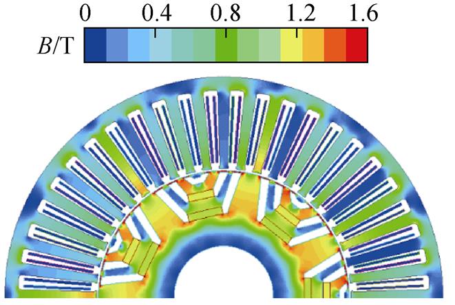
(a)模型Ⅰ
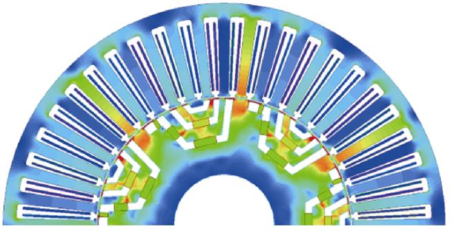
(b)模型Ⅱ
图11 空载磁通密度分布
Fig.11 Distributions of no-load magnetic density
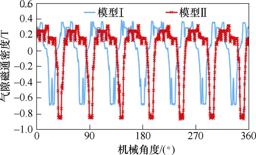
图12 气隙磁通密度
Fig.12 Air gap flux density
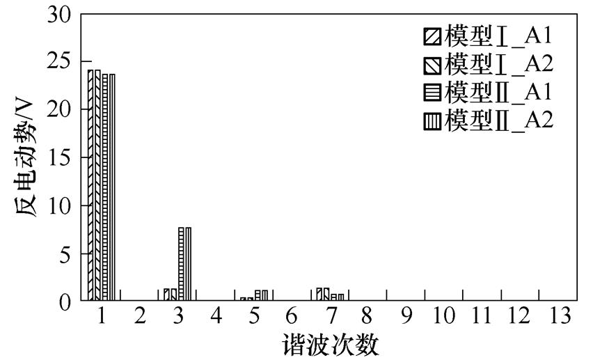
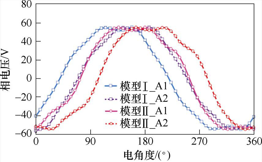
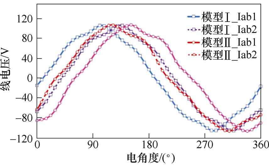
图13为PMaSynRM两种模型的空载反电动势及其谐波分析。可知,A1相反电动势幅值与A2相相等;模型Ⅰ和Ⅱ的A1相反电动势幅值分别为26.3 V和32.9 V。相比于模型Ⅰ,模型Ⅱ的空载反电动势幅值提升了25%,主要是3次谐波较大。然而,该3次谐波反电动势在相电压和线电压幅值中占比很小;另外,由于电机绕组星形联结,线电压中不含3次谐波反电动势。由图14可知,模型Ⅰ和Ⅱ在额定工况下的相电压和线电压几乎相同。因此,在相同的母线电压下,模型Ⅰ和Ⅱ的母线电压利用率几乎相同。此外,3次谐波反电动势不会导致转矩脉动[28]。
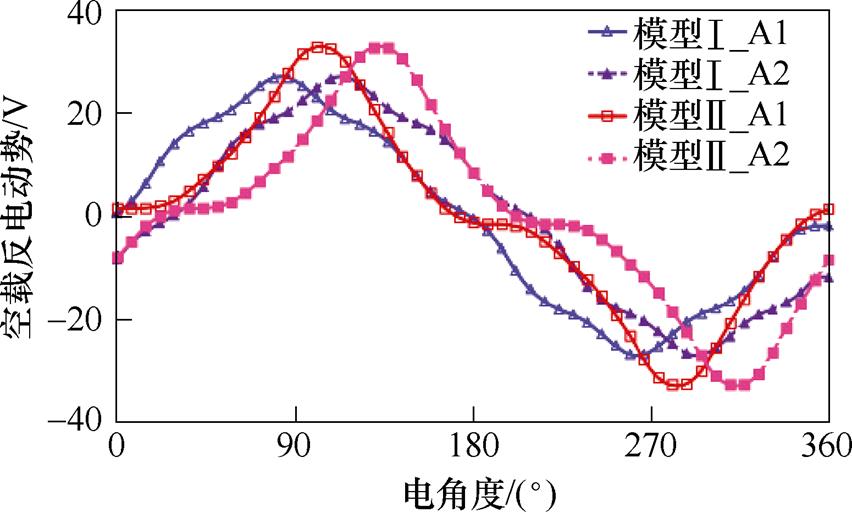
(a)A相反电动势波形
(b)谐波分析
图13 反电动势波形及谐波分析
Fig.13 Back-electromotive force and their harmonics
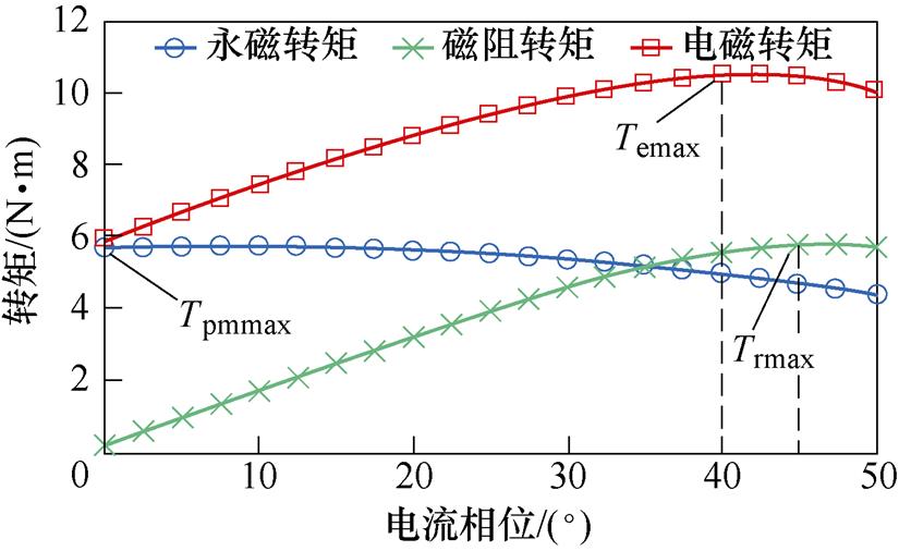
图15为PMaSynRM两种电机在额定转速1 200 r/min、电流12 A时,改变电流相位获得的转矩特性。可见,模型Ⅰ的永磁转矩最大值和磁阻转矩最大值对应的电流相位相差45°,且永磁转矩利用率仅为83%,磁阻转矩利用率为96%;在模型Ⅱ中永磁转矩利用率为100%,磁阻转矩利用率为100%。与模型Ⅰ相比,模型Ⅱ的永磁和磁阻转矩利用率分别提升了20.5%和4.2%,且永磁转矩最大值与磁阻转矩最大值所对应的电流相位重合,实现了永磁转矩和磁阻转矩的充分利用。
(a)相电压波形
(b)线电压波形
图14 模型Ⅰ和Ⅱ的相和线电压波形
Fig.14 Phase- and line-voltage waveforms of models Ⅰ and Ⅱ
(a)模型Ⅰ
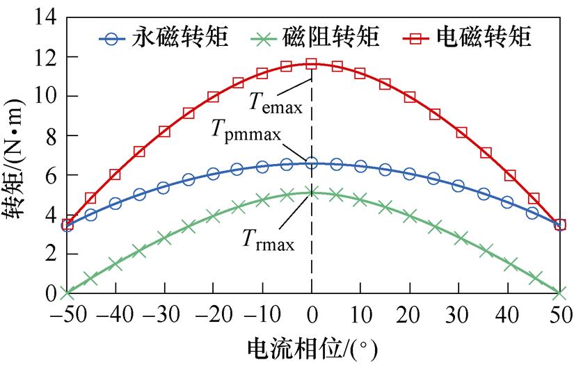
(b)模型Ⅱ
图15 模型Ⅰ与模型Ⅱ的实测转矩特性
Fig.15 Measured torque characteristics of Model Ⅰ and Model Ⅱ
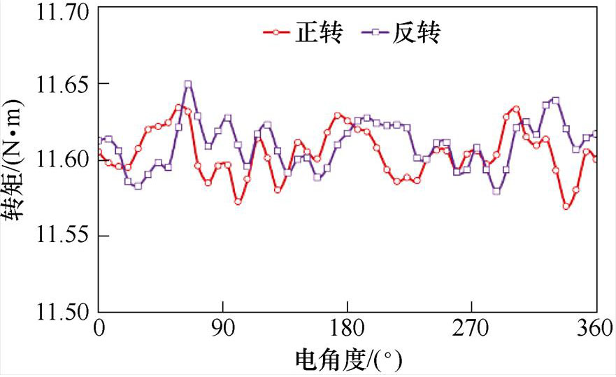
图16为PMaSynRM两种电机在额定转速1 200 r/min、电流12 A工况下的电机输出转矩波形。可见,模型Ⅰ和Ⅱ的平均转矩分别为10.5 N·m和11.6 N·m,转矩脉动分别为2%和1%。相比模型Ⅰ,模型Ⅱ的平均转矩提升了10.5%。具体性能参数对比见表3。图17为模型Ⅱ正、反转的空载反电动势和转矩波形。可见,电机正、反转时空载反电动势幅值相等;在额定转速1 200 r/min、电流12 A工况下,电机正、反转的平均转矩均为11.6 N·m。因此,该电机正、反转功能无差别。因此,所提出的ACP- PMaSynRM有效改善了PMaSynRM的转矩性能。
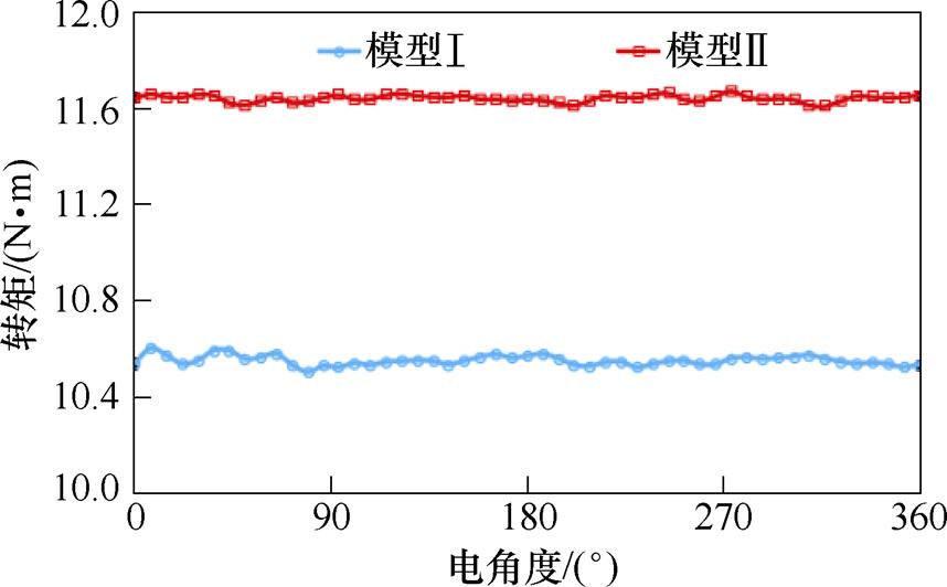
图16 输出转矩
Fig.16 Output torque
表3 模型Ⅰ和Ⅱ性能参数
Tab.3 Performance parameters of model Ⅰ and Ⅱ
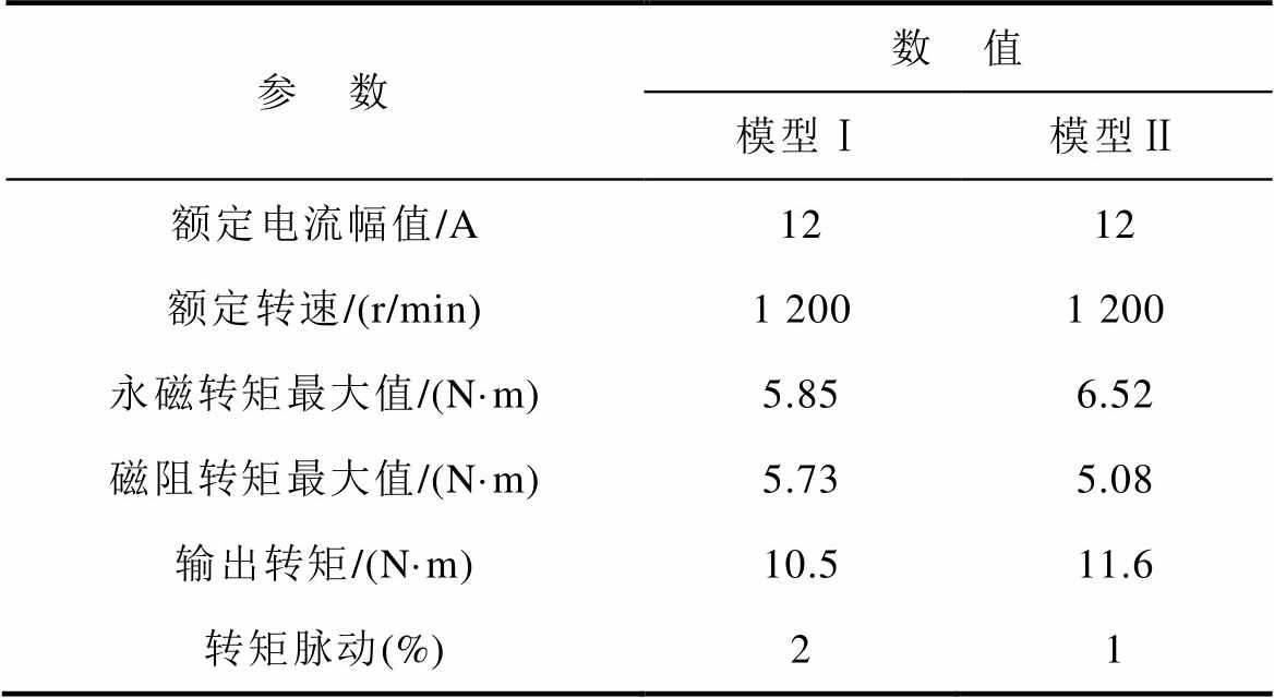
参 数数 值 模型Ⅰ模型Ⅱ 额定电流幅值/A1212 额定转速/(r/min)1 2001 200 永磁转矩最大值/(N·m)5.856.52 磁阻转矩最大值/(N·m)5.735.08 输出转矩/(N·m)10.511.6 转矩脉动(%)21
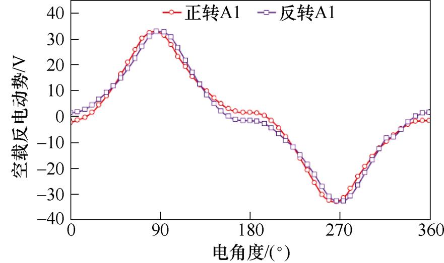
(a)空载反电动势
(b)输出转矩
图17 模型Ⅱ正、反转的空载反电动势和转矩波形
Fig.17 Back-back-electromagnetic fields and torque waveforms of model Ⅱ with forward and reverse rotation
为验证上述分析的有效性,根据表1中电机参数制造了一台48槽14极的ACP-PMaSynRM样机。图18为样机结构,图19为样机的实验平台。伺服电机、转矩传感器、光电编码器和样机轴向连接,磁粉制动器通过传送带与电机轴相连接。采用伺服电机拖动样机,测量样机在1 200 r/min时的反电动势。通过磁粉制动器加载,测量样机在额定转速1 200 r/min、额定电流12 A、电流相位0°时的转矩。
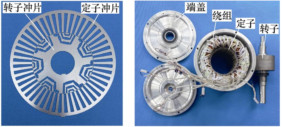
图18 样机结构
Fig.18 Prototype structure
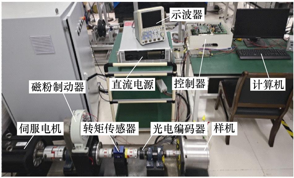
图19 实验平台
Fig.19 Experiment platform
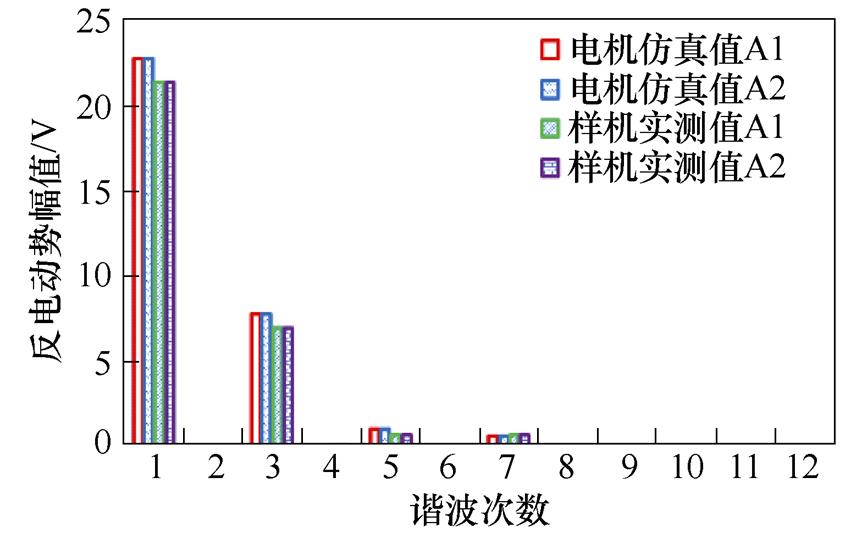
图20为仿真与样机实测的空载反电动势及傅里叶分析对比。样机的实测空载反电动势幅值略低于有限元仿真结果,这主要是由于加工制造误差所导致的。然而,实测波形与仿真波形基本相似,初步验证了电机设计的有效性。
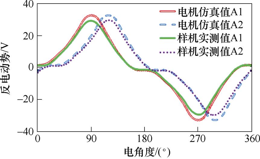
(a)反电动势
(b)傅里叶分析
图20 空载反电动势及傅里叶分析
Fig.20 Measured electromotive force and their Fourier analysis
图21为负载情况下样机的转矩和电流波形。可见,电机相电流波形较正弦,输出转矩平均值为10.7 N·m。因此,尽管反电动势存在3次谐波,但只要相电流不含谐波成分,3次谐波反电动势就不会导致转矩脉动,电机仍然能输出平滑的转矩。图22为ACP-PMaSynRM仿真与实测转矩对比。仿真和实测的平均转矩分别为11.6 N·m和10.7 N·m;仿真和实测的转矩脉动分别为1%和5%。实测转矩性能略低于有限元仿真结果,这主要是由于在样机制造过程中存在一定的机械误差、机械摩擦以及2D有限元分析无法考虑到的电机端部影响等。
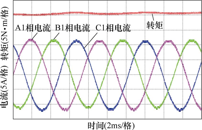
图21 转矩和电流波形
Fig.21 Torque and current waveforms
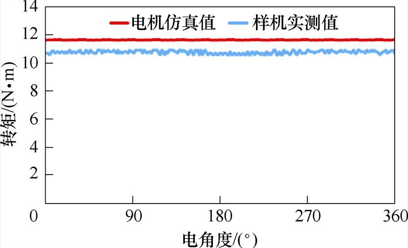
图22 仿真与实测转矩对比
Fig.22 Comparison of simulated and measured torques
本文提出了一种ACP-PMaSynRM拓扑,增强了永磁辅助同步磁阻电机输出转矩能力并降低了转矩脉动和永磁体用量。基于磁链相移原理,结合矢量图和转矩特性,分析了磁链相移角对永磁转矩和磁阻转矩的影响,并对该电机的永磁体进行参数优化,以实现永磁转矩和磁阻转矩在最大值时具有相同的电流相位。具体结论如下:
1)ACP-PMaSynRM不但提升了永磁体利用率,而且实现了永磁转矩和磁阻转矩的充分利用,提高了电机输出转矩能力。
2)相比传统PMaSynRM,ACP-PMaSynRM采用不对称交替极永磁阵列,其气隙磁通密度、空载反电动势以及输出转矩能力均有所提升,同时转矩脉动降低了。
3)反电动势3次谐波较大,需进一步研究以抑制反电动势谐波。
参考文献
[1] 吉敬华, 沈人洁, 徐亮, 等. 考虑运行工况的模块化双永磁游标电机多工作点优化设计[J]. 电工技术学报, 2022, 37(22): 5649-5659.
Ji Jinghua, Shen Renjie, Xu Liang, et al. Optimal design of modular double permanent magnet vernier motor with multi-working points considering oper- ating conditions[J]. Transactions of China Electro- technical Society, 2022, 37(22): 5649-5659.
[2] 孙毅, 蔡顺, 林迎前, 等. 永磁辅助同步磁阻电机顶层优化设计[J]. 电工技术学报, 2022, 37(9): 2306- 2318.
Sun Yi, Cai Shun, Lin Yingqian, et al. Top-level design pattern of PM-assisted synchronous reluctance machines[J]. Transactions of China Electrotechnical Society, 2022, 37(9): 2306-2318.
[3] 高锋阳, 齐晓东, 李晓峰, 等. 部分分段Halbach永磁同步电机优化设计[J]. 电工技术学报, 2021, 36(4): 787-800.
Gao Fengyang, Qi Xiaodong, Li Xiaofeng, et al. Optimization design of partially-segmented halbach permanent magnet synchronous motor[J]. Transa- ctions of China Electrotechnical Society, 2021, 36(4): 787-800.
[4] 戴睿, 张岳, 王惠军, 等. 基于多物理场近似模型的高速永磁电机多目标优化设计[J]. 电工技术学报, 2022, 37(21): 5414-5423.
Dai Rui, Zhang Yue, Wang Huijun, et al. Multi- objective optimization design of high-speed per- manent magnet motor based on multi-physical field approximation model[J]. Transactions of China Elec- trotechnical Society, 2022, 37(21): 5414-5423.
[5] 刘云飞, 张炳义, 宗鸣, 等. 基于非线性混合模型的模块组合式永磁电机磁场解析[J]. 电工技术学报, 2022, 37(18): 4593-4603.
Liu Yunfei, Zhang Bingyi, Zong Ming, et al. Mag- netic field analysis of modular permanent magnet motor based on nonlinear hybrid model[J]. Transa- ctions of China Electrotechnical Society, 2022, 37(18): 4593-4603.
[6] Du Longxin, Liu Xiping, Fu Jiesheng, et al. Design and optimization of reverse salient permanent magnet synchronous motor based on controllable leakage flux[J]. CES Transactions on Electrical Machines and Systems, 2021, 5(2): 163-173.
[7] Xiang Zixuan, Pu Weiling, Zhu Xiaoyong, et al. Design and analysis of a V-shaped permanent magnet vernier motor for high torque density[J]. CES Transactions on Electrical Machines and Systems, 2022, 6(1): 20-28.
[8] Liu Xiangdong, Chen Hao, Zhao Jing, et al. Research on the performances and parameters of interior PMSM used for electric vehicles[J]. IEEE Transa- ctions on Industrial Electronics, 2016, 63(6): 3533- 3545.
[9] Hu Yaohua, Zhu Shushu, Liu Chuang, et al. Electro- magnetic performance analysis of interior PM machines for electric vehicle applications[J]. IEEE Transactions on Energy Conversion, 2018, 33(1): 199-208.
[10] Zhu Shushu, Chen Weifang, Xie Mingqiu, et al. Electromagnetic performance comparison of multi- layered interior permanent magnet machines for EV traction applications[J]. IEEE Transactions on Mag- netics, 2018, 54(11): 1-5.
[11] Momen F, Rahman K, Son Y. Electrical propulsion system design of Chevrolet bolt battery electric vehicle[J]. IEEE Transactions on Industry Appli- cations, 2017, 55(1): 376-384.
[12] Anh H T, Hsieh M. Comparative study of PM-assisted SynRM and IPMSM on constant power speed range for EV applications[C]//2017 IEEE International Magnetics Conference (INTERMAG), Dublin, Ireland, 2017: 8008078.
[13] Cai Haiwei, Guan Bo, Xu Longya. Low-cost ferrite PM-assisted synchronous reluctance machine for electric vehicles[J]. IEEE Transactions on Industrial Electronics, 2014, 61(10): 5741-5748.
[14] Bianchi N, Bolognani S, Bon D, et al. Rotor flux-barrier design for torque ripple reduction in synchronous reluctance and PM-assisted synchronous reluctance motors[J]. IEEE Transactions on Industry Applications, 2009, 45(3): 921-928.
[15] Zhao Wenliang, Zhao Fei, Lipo T A, et al. Optimal design of a novel V-type interior permanent magnet motor with assisted barriers for the improvement of torque characteristics[J]. IEEE Transactions on Magnetics, 2014, 50(11): 1-4.
[16] Wang Bo, Wang Jiabin, Griffo A, et al. Experimental assessments of a triple redundant nine-phase fault- tolerant PMA SynRM drive[J]. IEEE Transactions on Industrial Electronics, 2019, 66(1): 772-783.
[17] Huynh T A, Hsieh M F. Irreversible demagnetization analysis for multilayer magnets of permanent magnet- assisted synchronous reluctance machines considering current phase angle[J]. IEEE Transactions on Mag- netics, 2019, 55(7): 1-9.
[18] Nobahari A, Vahedi A, Nasiri-Zarandi R. A modified permanent magnet-assisted synchronous reluctance motor design for torque characteristics improve- ment[J]. IEEE Transactions on Energy Conversion, 2022, 37(2): 989-998.
[19] Liu Zeyu, Hu Yan, Wu Jiacheng, et al. A novel modular permanent magnet-assisted synchronous reluctance motor[J]. IEEE Access, 2021, 9: 19947- 19959.
[20] Zhao Wenliang, Shen Haizhen, Lipo T A, et al. A new hybrid permanent magnet synchronous reluctance machine with axially sandwiched magnets for per- formance improvement[J]. IEEE Transactions on Energy Conversion, 2018, 33(4): 2018-2029.
[21] Liu Guohai, Xu Gaohong, Zhao Wenxiang, et al. Improvement of torque capability of permanent- magnet motor by using hybrid rotor configuration[J]. IEEE Transactions on Energy Conversion, 2017, 32(3): 953-962.
[22] Xu Gaohong, Liu Guohai, Zhao Wenxiang, et al. Principle of torque-angle approaching in a hybrid rotor permanent-magnet motor[J]. IEEE Transactions on Industrial Electronics, 2019, 66(4): 2580-2591.
[23] Zeng Xianxian, Quan Li, Zhu Xiaoyong, et al. Investigation of an asymmetrical rotor hybrid permanent magnet motor for approaching maximum output torque[J]. IEEE Transactions on Applied Superconductivity, 2019, 29(2): 1-4.
[24] Zhao Wenliang, Chen Dezhi, Lipo T A, et al. Performance improvement of ferrite-assisted syn- chronous reluctance machines using asymmetrical rotor configurations[J]. IEEE Transactions on Mag- netics, 2015, 51(11): 1-4.
[25] Mohammadi A, Mirimani S M. Design of a novel PM-assisted synchronous reluctance motor topology using V-shape permanent magnets for improvement of torque characteristic[J]. IEEE Transactions on Energy Conversion, 2022, 37(1): 424-432.
[26] Zhu Ziqiang, Xiao Yang. Novel magnetic-field- shifting techniques in asymmetric rotor pole interior PM machines with enhanced torque density[J]. IEEE Transactions on Magnetics, 2022, 58(2): 1-10.
[27] Baek J, Bonthu S S R, Choi S. Design of five-phase permanent magnet assisted synchronous reluctance motor for low output torque ripple applications[J]. IET Electric Power Applications, 2016, 10(5): 339- 346.
[28] Li Dawei, Qu Ronghai, Li Jian, et al. Analysis of torque capability and quality in vernier permanent- magnet machines[J]. IEEE Transactions on Industry Applications, 2016, 52(1): 125-135.
Abstract In recent years, with the rising price of permanent magnet materials, magnet motors with high efficiency, high torque density, and fewer permanent magnets have gained much attention. The electric propulsion system for high torque density, low torque ripple, and low-cost permanent magnet motor is required. This paper proposes a new asymmetric consequent-pole permanent magnet-assisted synchronous reluctance motor (ACP- PMaSynRM), which can enhance output torque, reduce torque ripple, and decrease permanent magnet amounts.
An ACP-PMaSynRM with 48 slots and 14 poles was designed based on the phase-shifting principle of permanent magnet flux linkage. Double three-phase double-layered distributed windings are adopted, and the flux barriers of the second and third layers are asymmetrical in the rotor. Additionally, the asymmetrical consequent-pole permanent magnets are embedded in the flux barriers of the second and third layers. The asymmetric rotor structure comprises the consequent-pole permanent magnets and the asymmetric flux barriers. The right flux barriers of the second and third layers are shifted by a phase angle l to the left. Therefore, the maximum value of permanent magnet flux-linkage is shifted by an angle g from the traditional d-axis to the new d1-axis, thus forming a new d1-q1 coordinate system. Therefore, it can be deduced that the output torque of ACP-PMaSynRM in the d1-q1 coordinate system is

It can be noticed that Tpm and Tr simultaneously reach the maximum value when g =p/4 and b2=0.
Using the finite element method (FEM), the structural parameters of permanent magnets were optimized to fully utilize the permanent magnet and reluctance torque. Compared with traditional PMaSynRM, the amount of permanent magnet of ACP-PMaSynRM is reduced by 9.9%. The fundamental component of back-EMF of ACP-PMaSynRM is almost the same as that of traditional PMaSynRM. Meanwhile, the utilization of permanent magnet and reluctance torque of ACP-PMaSynRM is increased by 20.5% and 4.2%, respectively. The current phase angles corresponding to the maximum permanent magnet torque and the maximum reluctance torque are the same, thus realizing the full utilization of the permanent magnet and reluctance torque. Therefore, compared with the traditional PMaSynRM, the average torque of ACP-PMaSynRM is increased by 10.5%, and the torque ripple is reduced by 50%. Finally, a prototype with 48 slots and 14 poles was fabricated to verify its feasibility. The measured results are almost consistent with the simulation.
The following conclusions can be drawn: (1) ACP-PMaSynRM can improve the utilization rate of the permanent magnet, realize the full utilization of permanent magnet and reluctance torque, and enhance output torque capability. (2) Compared with traditional PMaSynRM, ACP-PMaSynRM uses an asymmetric consequent- pole permanent magnet array, which can improve the air-gap magnetic density, back-EMF, and output torque capacity while reducing torque ripple. (3) The third harmonic back-EMF is high, and further research is needed to suppress the harmonic.
keywords:Permanent magnet assisted synchronous reluctance motor, consequent-pole, flux-linkage phase shifting, maximum torque
中图分类号:TM352
DOI: 10.19595/j.cnki.1000-6753.tces.221805
国家自然科学基金(52277052)和江苏高校“青蓝工程”资助项目。
收稿日期 2022-09-23
改稿日期 2022-10-20
周华伟 男,1980年生,教授,博士生导师,研究方向为电动汽车和电磁悬架用特种永磁电机驱动控制、容错控制等。E-mail: zhouhuawei@ujs.edu.cn(通信作者)
龙顺海 男,1997年生,硕士研究生,研究方向为永磁电机设计。E-mail: 1209289150@qq.com
(编辑 崔文静)