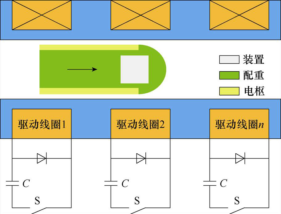
图1 同步线圈发射器原理示意图
Fig.1 Schematic diagram of synchronous coil launcher
摘要 该文提出多级同步感应线圈发射器弹载存储动态测试技术。首先,基于电磁场理论定量分析了同步感应线圈发射器发射过程中存在的强脉冲和高过载环境;其次,设计具有抗电磁干扰且抗高过载能力的弹载存储测试装置,并分析了装置的屏蔽效能和承载能力;最后,研制带弹载存储测试装置的测试弹,并开展了30级同步感应线圈发射器动态发射试验,得到同步感应线圈发射器动态过程中磁感应强度数据和加速度数据,与仿真数据吻合,且误差可控制在4.7%,同时揭示了发射始末测试弹存在“规律碰撞”效应和“周期章动”现象。
关键词:同步感应线圈发射器 弹载存储测试 磁感应强度 屏蔽效能
同步感应线圈发射技术属于电磁发射技术中的一种,与化学能发射技术相比,具有更高的发射速度、较低的发射成本、较短的准备周期等一系列优点,在速度、射程、威力、精度、安全性、灵活性及保障性等方面具有革命性的突破,使得其在武器装备、近地卫星、高速导弹等领域内具有广泛的应用前景[1-5]。
随着电磁发射技术的日趋成熟,电磁武器测试技术研究逐步开展,目前主要以非接触外测法研究为主,王韶霞、贾学松等利用对射型光电开关传感器组实现电磁发射弹丸速度测量[6-7],李松乘等利用高速摄像技术进行轨道炮的弹丸姿态测量[8]。虽然化学能武器弹载存储测试技术研究相当成熟,可以适应高达上十万g的冲击过载环境,应用至空中导弹、陆上炮弹至海上鱼雷等多型兵器测试[9-11],为武器研制与装备提供了真实全面的试验数据体系,但是受限于电磁发射过程中强脉冲磁场和高过载环境影响,电磁武器弹载存储测试技术仍存在技术空白与差距,不能形成完备的试验数据体系。
基于此,本文开展同步感应线圈发射器发射环境分析,融合化学武器弹载存储测试技术开展线圈武器弹载测试系统设计与分析,并利用同步感应线圈发射器完成动态发射试验,最后形成同步感应线圈发射器弹载存储测试技术。
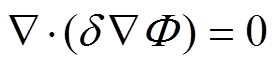
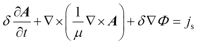
同步感应线圈发射器主要由多级驱动线圈和测试弹组成,其中测试弹包括金属电枢、非金属配重和弹载存储测试装置。同步线圈发射器原理示意图如图1所示,当驱动线圈依次通过脉冲电流时产生磁行波推动测试弹向前加速运动。建立研究区域的数学描述方法,研究区域用W 表示,驱动线圈占据子域W1,电枢和弹载存储测试装置分配子域W2,包围驱动线圈和测试弹的空气区域及非金属配重形成子域W3,若驱动线圈中源电流密度js为已知量,引入辅助量矢量磁位A和标量电位F,推导同步感应线圈发射器电磁场控制方程组。
图1 同步线圈发射器原理示意图
Fig.1 Schematic diagram of synchronous coil launcher
 (1)
(1)
 (2)
(2)
式中, 为电导率;
为电导率; 为磁导率。
为磁导率。
基于电磁场控制方程得到矢量磁势A和标量电位 表达式,发射过程中空间磁感应强度B和电枢瞬态电磁力F可分别表示为
 (3)
(3)
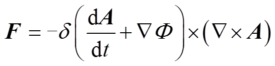 (4)
(4)
采用有限元软件仿真同步感应线圈发射器发射过程,忽略测试弹径向微小运动,只考虑轴向运动,建立30级驱动线圈模型,加载脉冲电流依次触发驱动线圈,测试弹尾部对齐第1级线圈中心位置,测试弹质量保持不变。驱动线圈利用多股多匝扁铜线绕制而成,测试弹选择圆筒形铝合金和玻璃纤维材料粘结成型,具体参数见表1。
表1 同步感应线圈发射器参数
Tab.1 Launcher parameters of synchronous induction coil launcher
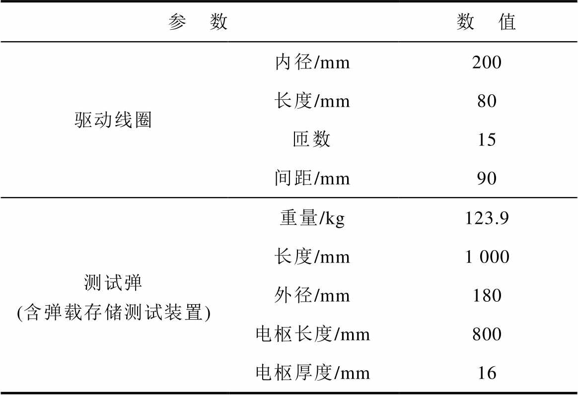
参 数数 值 驱动线圈内径/mm200 长度/mm80 匝数15 间距/mm90 测试弹 (含弹载存储测试装置)重量/kg123.9 长度/mm1 000 外径/mm180 电枢长度/mm800 电枢厚度/mm16
1.2.1 磁场环境分析
测试弹轴线磁感应强度云图如图2所示,以电枢尾部为初始0 mm,起始位置时刻为发射0 s,测试弹轴线处轴向磁感应强度随发射时间先增大后减小,且电枢尾部磁感应强度值始终大于电枢头部,在电枢尾部0~400 mm区域峰值达4.2 T,而在电枢头部800 mm以外区域峰值小于0.5 T;测试弹轴线处径向磁感应强度变化规律与轴向磁感应强度一致,但尾部区域幅值(<0.2 T 远小于轴向,且在发射时间末(即电枢尾部离开最后一级驱动线圈时)磁感应强度突变为负值。该现象也间接证明了同步感应线圈发射器发射过程中截获效应的存在[12]。
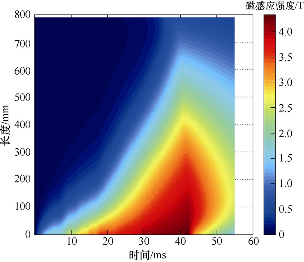
(a)轴向磁感应强度
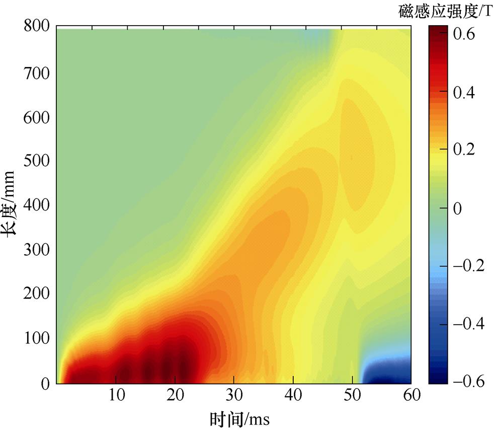
(b)径向磁感应强度
图2 测试弹轴线磁感应强度云图
Fig.2 Cloud diagram of magnetic induction intensity of test projectile axis
1.2.2 过载环境分析
测试弹轴向推力曲线如图3所示,以电枢尾部为初始0 mm,起始位置时刻为发射0 s,测试弹推力随发射时间呈周期性波动,与驱动线圈触发过程相对应:第一级驱动线圈触发初始,测试弹轴向推力波动幅度最大,在2.2 ms内推力增加至778.3 kN(加速度628.1 g);之后,随驱动线圈依次触发,测试弹轴向推力波动幅度逐步变小,并趋向平稳,维持在750 kN(加速度605.2 g)上下波动;至最后一级驱动线圈触发时,测试弹轴向推力瞬间变负,其幅值达-457 kN(加速度-368.8 g)。此外,最后一级驱动线圈位置测试弹推力方向突变直接证明了同步感应线圈发射器发射过程中截获效应的存在[13]。
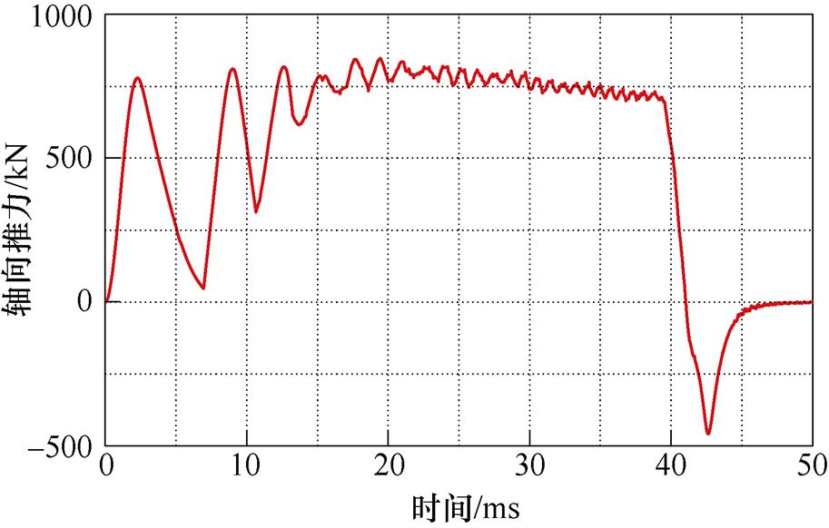
图3 测试弹轴向推力曲线
Fig.3 Axial thrust curve of test projectile
基于上述同步感应线圈发射器发射环境分析,弹载存储测试装置主要承受发射过程中强脉冲电磁环境和大过载冲击环境。弹载存储测试装置布局示意图如图4所示。弹载存储测试装置最大外径120 mm,高度100 mm,布置于测试弹头部位置,用于实现发射过程中轴向磁场强度和加速度测试,由图4可知,测试装置主要由屏蔽壳体、缓冲材料和电路模块三部分组成。屏蔽壳体用于与测试弹连接,并提供电磁防护。缓冲材料用于填充内部空间,并提供过载防护。电路模块用于自动采集存储数据。

图4 弹载存储测试装置布局示意图
Fig.4 Diagram of missile-borne storage test device layout
电路模块采用微型化设计,电源模块、电源转换电路、MSP430控制器、时钟模块、单轴磁场/加速度传感器、磁/加速度信号调理电路、16bitADC转换器、FPGA处理器、FLASH存储器和USB控制器集成为一体。其中,单轴磁场传感器选用TMR2105惠斯通全桥磁结构,灵敏度为0.3×10-4 mV/T,饱和磁感应强度±0.1 T,单轴加速度传感器选用MEAS电子式3038-6000,测量范围为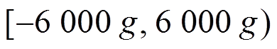 ,灵敏度0.05 mV/g,带宽5 MHz。MSP430控制器是弹载存储测试装置控制器,负责参数设定、并协调内部各个模块工作时序、测试装置工作模式选择,控制FPGA处理器采集存储传输信号。弹载存储测试装置工作原理框图如图5所示,测试弹发射前,通过计算机指令擦除FLASH存储器,同步时钟模块授时,并设置工作参数,此时弹载存储测试装置上电完成,且只有时钟系统和MSP430控制器处于工作状态,处于低功耗状态。当到设定的工作时间后,FPGA控制器开始采集磁场传感器数据和加速度传感器数据,并把数据存储至FLASH存储器中。当到达设定的最大工作时长后,测试装置停止采集数据,再次进入低功耗状态,后通过USB控制器将FLASH存储器中的数据上传至计算机。
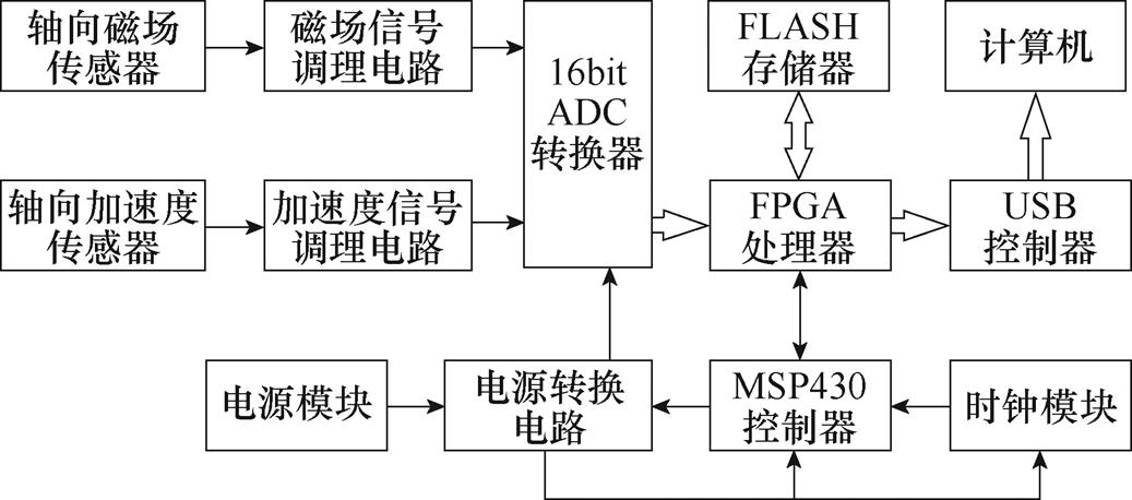
图5 弹载存储测试装置工作原理框图
Fig.5 Working principle block diagram of missile-borne storage test device
2.3.1 屏蔽效能
同步感应线圈发射器干扰环境主要原因为脉冲大电流在发射器内产生的强磁场,具有磁感应强度大、频率范围低、瞬态变化等特点。磁场环境屏蔽机理可以分为主动屏蔽、被动屏蔽和半主动屏蔽,其中被动屏蔽为由导电材料或导磁材料组成的单层或者多层屏蔽体[14-17]。基于此,本文选择被动方式实现弹载存储测试装置屏蔽,屏蔽壳体结构布局如图6所示,设计5 mm厚玻莫合金材料作为最外层壳体,镶嵌5 mm厚尼龙材料作为中间隔离层,5 mm厚铝合金材料作为内部壳体,其中,磁场传感器置于测试弹轴线位置且距电枢头部100 mm。
图6 屏蔽壳体结构布局
Fig.6 Diagram of shielding shell structure layout
建立带弹载存储测试装置屏蔽壳体的仿真模型,采用有限元软件仿真同步感应线圈发射器发射过程,以磁场传感器布置点A作为动态观测点,动态观测点A磁感应强度曲线如图7所示。图7中,无屏蔽时动态观测点A的磁感应强度随发射时间逐渐变大,峰值为0.308 T,且在发射初始增幅较小,在发射末段由于驱动线圈触发点相对电枢位置前移从而使得增幅变大;带屏蔽壳时动态观测点A的磁感应强度随发射时间缓慢增大,峰值为0.019 T,且由于屏蔽壳体作用使得峰值时间延后。综合对比无屏蔽时和带屏蔽壳体两种工况,测试弹发射过程中动态观察点A的平均屏蔽效能为28.16 dB,屏蔽壳体内部磁感应强度降低,低于电路模块承受电磁干扰的能力。

图7 动态观测点A磁感应强度曲线
Fig.7 Magnetic induction intensity curves of dynamic observation at point A
2.3.2 承载能力
同步感应线圈发射器主要过载环境为测试弹运动过程中产生的加速度场,具有过载大、波动幅度大、瞬时变化等特点。冲击环境防护措施主要采取灌封环氧树脂加固和高性能缓冲材料防护两种[18]。本文选择灌封环氧树脂加固措施实现弹载存储测试装置防护,屏蔽壳体与电路模块间的空腔填充加强型环氧树脂[19],凝固后弹性模量为25 GPa,抗拉强度为200 MPa,密度为1 850 kg/m3,利用有限元软件建立瞬态动力学分析模型,加载测试弹发射过载曲线,测试系统最大应力分布云图如图8所示,弹载存储测试装置最大应力处为加强型环氧树脂与电路模块接触处,此时测试弹发射加速度最大,发射时间为12.65 ms,最大应力为59.73 MPa,小于材料最大抗拉强度。
图8 测试系统最大应力分布云图
Fig.8 Cloud diagram of the maximum stress distribution of the test system
本文利用30级同步感应线圈发射器进行测试弹动态发射试验,如图9所示,弹载存储测试装置利用六组螺钉固定在测试弹头部。试验开始前,测试弹放置于同步感应线圈发射器第一级线圈中间位置,利用计算机对弹载测试装置设定参数(采样频率5 kHz,工作时间5 min),并完成授时。试验过程中,驱动线圈脉冲电源采用电容器储能,电容为10 mF,充电电压为4 000 V,采用固定时序触发,同步感应线圈发射器触发时序见表2。试验完成后,回收测试弹待弹载存储测试装置采集时间到,利用计算机读取磁感应强度数据与轴向加速度数据,弹载存储测试装置数据回传现场图如图10所示。
图9 测试弹实物图
Fig.9 Test projectile physical image
表2 同步感应线圈发射器触发时序
Tab.2 Trigger timing of synchronous induction coil launcher (单位: ms)
级 数数 值级 数数 值 10413.25 26.95515.35 310.65617.05
(续)

级 数数 值级 数数 值 718.601930.85 819.952031.65 921.252132.40 1022.402233.15 1123.552333.90 1224.602434.60 1325.602535.30 1426.552636.00 1527.452736.65 1628.352837.30 1729.202937.95 1830.053038.60
图10 弹载存储测试装置数据回传现场图
Fig.10 Scene image of data return of missile storage test device
测试弹发射初始时间点记为0 ms,选择测试弹发射过程0~50 ms时间段中动态观察点A的磁感应强度数据进行分析,即轴向磁场传感器安装位置,随发射时间增加,轴向磁感应强度实测值与仿真值变化规律一致,但轴向磁感应强度实测值较仿真值偏大,且在发射末段波动较大。
当测试弹通过第1~第3级线圈时,即采样时间10 ms以内,轴向磁感应强度实测值接近0,此时屏蔽效果较好。当测试弹通过第4~29级线圈时,即采样时间在10~42 ms内,轴向磁感应强度实测值增加幅度高于仿真值,峰值达0.020 T,屏蔽效果降低;当测试弹离开最后一级线圈时,轴向磁感应强度实测值出现剧烈抖动,幅值可达0.029 T;综合上述现象,分析认为是仿真过程中未考虑安装基座、缓冲装置等的影响,从而出现数值偏差和发射末段数值抖动。
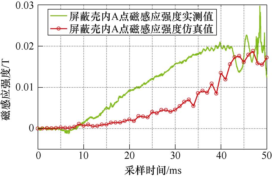
图11 磁感应强度测试数据
Fig.11 Magnetic induction intensity test data
测试弹发射初始时间点记为0 ms,选择测试弹发射过程0~50 ms时间段中加速度数据进行分析,测试弹轴向加速度数据如图12所示。轴向加速度仿真数据由图3测试弹轴向推力曲线除以测试弹(含弹载存储测试装置)质量123.9 kg得到,轴向加速度数据实测值与仿真变化规律吻合,但轴向加速度数据实测值较仿真值偏大,且在发射始末轴向加速度数据实测值抖动幅度较大。
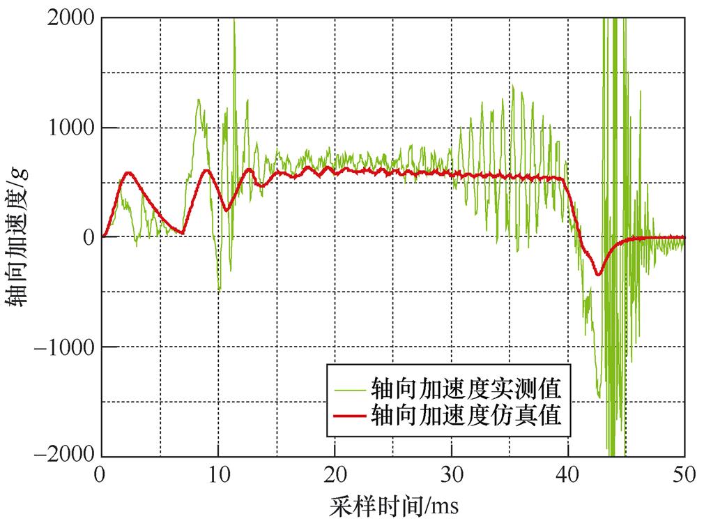
图12 测试弹轴向加速度数据
Fig.12 Axial acceleration data of test projectile
当测试弹通过第1~3级驱动线圈时,轴向加速度数据实测值明显失真,呈现“规律碰撞”效应,分析认为发射初始时刻测试弹在重力作用下靠近驱动线圈底部,当加载脉冲电流时在径向电磁力作用下推动测试弹向上移动,且由于电磁力作用集中在测试弹电枢尾部产生偏心矩,使得测试弹俯仰,从而导致测试弹与驱动线圈内壁产生周期性碰撞,出现轴向加速度实测值抖动。
当测试弹通过第4~16级驱动线圈时,轴向加速度数据实测值均值634.1 g,与仿真值均值605.2 g相比,误差4.7%,分析认为此时径向电磁力作用点与幅值和测试弹总体参数达到动态运动平衡状态,实现悬浮运动,此外由于仿真值未考虑安装基座、缓冲装置的影响,将出现数值偏差。
当测试弹通过第17~30级驱动线圈时,轴向加速度数据实测值波动变大,呈现“周期章动”现象,分析认为发射末段时刻轴向电磁力作用点前移至测试弹电枢中间位置,当脉冲电流提前或者延后触发导致轴向电磁力在中间位置周期性交替变化,从而导致测试弹呈轴向周期性章动,出现轴向加速度实测值大幅度波动。此外,当测试弹离开最后一级驱动线圈时,出现加速度突变为负,这也验证了上述描述的截获效应现象。
综上所述,同步感应线圈发射器运用弹载存储测试技术获得了测试弹发射过程中轴向磁场强度与轴向加速度数据,验证了同步感应线圈发射器动态发射的客观规律,同时揭示了同步感应线圈发射器发射过程中存在的固有问题。
本文采用对射型光电开关在30级同步感应线圈发射器炮管口对测试弹出管速度测试,在炮管出口处安装两级间距154 mm对射型光电开关,利用示波器记录时间,如图13所示,测试弹通过时间798.3 ms,计算测试弹出炮管口速度192.9 m/s。
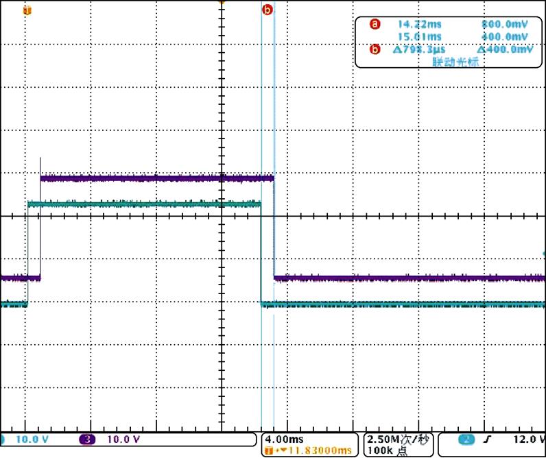
图13 测试弹轴向速度实测值
Fig.13 Axial speed experimental data of test projectile
基于测试弹轴向加速度实测值推导发射速度积分值,如图14所示,测试弹发射速度积分值与仿真值变化规律吻合,但受“规律碰撞”效应影响,在发射初始发射速度积分值增加低于仿真值,受“周期章动”现象影响,在发射末端发射速度积分值波动且变化幅度大于仿真值。此外,测试弹完全出炮管发生在45.1 ms,出口速度积分值为192.7 m/s,出口速度仿真值为195.0 m/s,与仿真值相比误差1.18%,与对射型光电开关测试值相比误差0.1%。综上所述,由于测试弹的发射速度积分值考虑了测试弹发射过程中的“碰撞与章动”,从而测试弹的积分值与对射型光电开关测试值更接近,与实际情况相符。
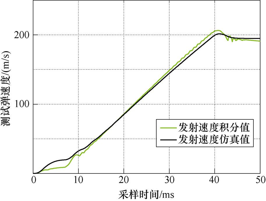
图14 测试弹轴向速度数据
Fig.14 Axial speed data of test projectile
本文基于有限元软件分析了同步感应线圈发射器电磁发射环境,设计了弹载存储测试装置抗电磁干扰和抗高过载防护措施,并完成了30级同步感应线圈发射器发射测试弹的动态试验,获得了有效的轴向磁感应强度数据和轴向加速度测试数据,验证了弹载存储测试技术在同步线圈感应发射器中应用可行性。
此外,由于只开展了单向测试,且发现了测试弹初始碰撞、末段波动的现象,为后续开展同步感应线圈发射器载体多自由度运动研究提供了依据。
参考文献
[1] 马伟明, 鲁军勇. 电磁发射技术[J]. 国防科技大学学报, 2016, 38(6): 1-5.
Ma Weiming, Lu Junyong. Electromagnetic launch technology[J]. Journal of National University of Defense Technology, 2016, 38(6): 1-5.
[2] Hasirci U, Balikci A, Zabar Z, et al. Concerning the design of a novel electromagnetic launcher for earth- to-orbit micro- and nanosatellite systems[J]. IEEE Transactions on Plasma Science, 2011, 39(1): 498- 503.
[3] 王群, 耿云玲. 电磁炮及其特点和军事应用前景[J].国防科技, 2011, 32(2): 1-7.
Wang Qun, Geng Yunling. Electromagnetic gun and its characteristics and military application[J]. National Defense Science & Technology, 2011, 32(2): 1-7.
[4] Turman B N. Coilgun launcher for nanosatellites[R]. Office of Scientific & Technical Information Tech- nical Reports, 1999.
[5] 马伟明, 鲁军勇. 电磁发射技术的研究现状与挑战[J]. 电工技术学报, 2023, 38(15): 3943-3959.
Ma Weiming, Lu Junyong. Research progress and challenges of electromagnetic launch technology[J]. Transactions of China Electrotechnical Society, 2023, 38(15): 3943-3959.
[6] 王韶霞, 王玉晶, 王慧锦. 电磁发射实验中的测速系统研究[J]. 鲁东大学学报, 2012, 28(3): 231-234.
Wang Shaoxia, Wang Yujing, Wang Huijin. Research on velocity measuring system in the electromagnetic launching experiment[J]. Ludong University Journal, 2012, 28(3): 231-234.
[7] 贾学松. 三级感应线圈型电磁发射器系统仿真及实验研究[D]. 合肥: 安徽大学, 2018.
[8] 李松乘, 鲁军勇, 程龙, 等. 电磁发射装置弹丸弹道姿态测量[J]. 电工技术学报, 2020, 35(23): 4835-4842.
Li Songcheng, Lu Junyong, Cheng Long, et al. Research on ballistic attitude measurement of pro- jectile in electromagnetic launcher[J]. Transactions of China Electrotechnical Society, 2020, 35(23): 4835- 4842.
[9] 王永峰. 基于微小型测试仪的侵彻过载测试技术研究[D]. 太原: 中北大学, 2016.
[10] 杨文卿. 高过载强磁高温复合环境下弹载测试系统设计[D]. 太原: 中北大学, 2019.
[11] 牛明杰. 战斗部侵彻过载参量存储测试系统研究[D]. 南京: 南京理工大学, 2018.
[12] 管少华, 关晓存. 多级同步感应线圈发射器电枢内部强磁场屏蔽与优化[J]. 电工技术学报, 2020, 35(2): 333-340.
Guan Shaohua, Guan Xiaocun. Shield of armature of multi-stage synchronous induction coil launcher internal high magnetic field and optimization[J]. Transactions of China Electrotechnical Society, 2020, 35(2): 333-340.
[13] Zhang Y, Gang X, Gong Y, et al. Armature structure research of a synchronous induction coil launcher[J]. IEEE Transactions on Plasmaence, 2017, 45(7): 1574- 1578.
[14] 廖桥生, 张祥金, 李豪杰, 等. 轨道炮弹丸所处强磁场环境屏蔽设计与仿真[J]. 火炮发射与控制学报, 2016, 37(2): 67-72.
Liao Qiaosheng, Zhang Xiangjin, Li Haojie, et al. Simulation of in-bore high magnetic shielding for railgun projectile[J]. Journal of Gun Launch & Control, 2016, 37(2): 67-72.
[15] Bologna M, Marracci M, Micheletti R, et al. Resonant shield concept as alternative solution in railguns[J]. IEEE Transactions on Plasma Science, 2015, 43(5): 1628-1633.
[16] Cui Shumei, Wang Shaofei, Wu Shaopeng. Magnetic field shielding of electromagnetic launch missile[C]// 19th IEEE Pulsed Power Conference (PPC), San Francisco, 2013: 1-4.
[17] Becherini G, Fraia S D, Ciolini R, et al. Shielding of high magnetic fields[J]. IEEE Transactions on Mag- netics, 2009, 45(1): 604-609.
[18] 王建坤. 高速深侵彻过程测试关键技术的研究[D].太原: 中北大学, 2015.
[19] 王耀先. 复合材料结构设计[M]. 北京: 化学工业出版社, 2001.
Missile-Borne Storage Testing Technology Research of Synchronous Induction Coil Launcher
Abstract With the maturity of electromagnetic launch technology, research on electromagnetic weapon test technology is gradually carried out. Due to the influence of a strong pulsed magnetic field and high overload environment in the electromagnetic launch, current research focuses on the non-contact external measurement method, and the on-board storage test technology of electromagnetic weapons has not formed a comprehensive test data system. Therefore, this paper analyzes the launching environment of the synchronous induction coil launcher, then designs the missile-borne test system. After the dynamic launch test verification, the missile-borne storage test technology of the synchronous induction coil launcher is finally formed.
Firstly, the simulation model of synchronous induction coil emitter is established by taking the multistage drive coil and the testing projectile as the research object. (1) The axial magnetic induction intensity of the test projectile increases first and then decreases with the launch time. The peak value at the tail area of the armature reaches 4.2 T, and the variation in radial magnetic induction intensity is consistent with that in the axial direction. However, the amplitude in the tail area is much smaller than in the axial direction. (2) The thrust of the test projectile fluctuates periodically with the launch time. The thrust of the initial test projectile, triggered by the first-stage driving coil, reaches its maximum axial value at 778.3 kN within 2.2 ms and then stabilizes, fluctuating around 750 kN. When the last stage driving coil is triggered, the axial thrust instantaneously becomes negative, reaching a peak amplitude of -457 kN.
Secondly, a missile-borne storage test device is designed and placed at the test warhead. The miniaturized circuit module is equipped with a uniaxial magnetic field/acceleration sensor to realize the automatic triggering test of the axial acceleration and internal magnetic induction intensity. Choose the passive mode to realize the shielding design with special materials for the outer layer, isolation layer, and internal shell. Compared with no shielding conditions, the average shielding efficiency is 28.16 dB, lower than the circuit module to withstand electromagnetic interference requirements. The potting epoxy resin reinforcement measures are selected to realize protection. The maximum stress is found at the contact point between the reinforced epoxy resin and the circuit module, where the test projectile has the maximum launch acceleration, the launch time is 12.65 ms, and the maximum stress is 59.73 MPa less than the maximum tensile strength of the material.
Thirdly, the dynamic launching test platform of the synchronous induction coil is built, parameters are set by the computer, and data are collected after testing. The measured axial magnetic induction intensity is consistent with the simulation but larger than the simulation value and fluctuates greatly at the end of the launch. The installation base, buffer device, and other factors are not considered. The measured axial acceleration data are consistent with simulations. However, the test projectile presents a “regular collision” effect during the first three levels of the driving coil. The measured axial acceleration from the fourth to the 16th level is 634.1 g (4.7% error compared with the simulation value). At this time, the test projectile presents a “suspension” characteristic. The test projectile presents the phenomenon of “periodic nutation” at the 17th to 30th level of the drive coil, and the integral value of its exit velocity is deduced to be 192.7 m/s. The error is 1.17% compared with the simulation value and 0.1% compared with the test value of the thru-beam photoelectric switch. The analysis shows that the integral value is closer to the test value, consistent with the actual situation.
Finally, through the dynamic test of the test projectile launched by the 30-stage synchronous induction coil launcher, the effective axial magnetic induction intensity data and axial acceleration test data are obtained, which verified the feasibility of the missile-borne storage test technology in the synchronous induction coil launcher. Since only a one-way test is carried out, and the phenomenon of initial collision and final fluctuation is found, it provides a basis for the subsequent research on the multi-DOF motion of synchronous induction coil launcher carriers.
keywords:Synchronous induction coil launcher, missile-borne storage test, magnetic induction intensity, shielding efficiency
中图分类号:TM836
DOI: 10.19595/j.cnki.1000-6753.tces.222037
国家自然科学基金资助项目(51777212)。
收稿日期 2022-10-23
改稿日期 2022-11-25
石敬斌 男,1988年生,博士研究生,研究方向电磁发射技术。E-mail: 18734142381@163.com
管少华 男,1991年生,博士,讲师,研究方向为电磁发射技术。E-mail: shaohuag511@163.com(通信作者)
(编辑 郭丽军)