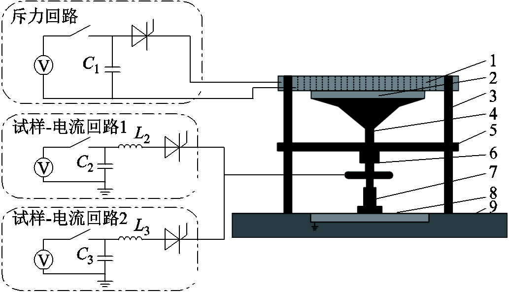

图1 电磁发射等价模拟实验装置
Fig.1 Electromagnetic emission equivalence simulation experimental device
摘要 材料在高速冲击下产生绝热剪切带,电辅助电磁成形技术通过在试样变形同时通入电流可增强材料塑性变形能力,但脉冲电流对绝热剪切带的作用规律目前尚不明晰,制约了材料在超高速冲击环境下的应用。该文设计了一种偏轴长杆箍件试样,通过脉冲功率源和电磁斥力盘开展了2A10铝合金在极端多物理场环境下即电流密度为108~109 A/m2,应变率≥104/s的动态变形特性研究。对试样进行金相处理后可观测到材料微观特征的演化过程,对比不同条件下微观特征分布得到了极端多物理场条件下电流密度对材料动态变形的作用规律。结果表明,施加电流后裂纹和绝热剪切带的长度减少,且长度随电流密度增大而逐渐减少。
关键词:超高速冲击 电流密度 绝热剪切带 裂纹
电磁发射是一种新型的超高速发射方式[1-5],在几毫秒时间内能够将电枢加速至几千米每秒,其结构包含两条平行轨道和一个位于轨道内的C型电枢。脉冲功率源对轨道电枢回路施加电流,电枢受到洛伦兹力加速向前移动。在电磁发射过程中,大电流产生大量焦耳热,因此电枢和轨道接触面产生烧蚀[6]。绝热剪切带是材料在高应变率冲击条件下的塑性变形高度局域化,普遍存在于爆炸、高速冲压成型、切削加工和侵彻等过程[7]。火箭橇实验中火箭橇和轨道在高应变率与高温升条件下的超高速冲击会在轨道产生刨坑,在刨坑底部发现有绝热剪切带[8]。由于轨道不平整、轨道振动等原因,电枢和轨道之间同样会在大电流、强磁场和高温升的条件下产生超高速冲击,轨道因此产生擦伤和刨削,刨坑底部可能产生绝热剪切带。但由于发射过程复杂及枢轨接触面烧蚀等原因,绝热剪切带特征被掩盖,目前尚未有研究在电磁发射形成的刨坑底部发现有绝热剪切带。张静等[9]通过分离式霍普金斯压杆对Ti-6Al-4V帽型试样进行了压缩实验,在帽型肩部观测到绝热剪切带。Li Diquan [10]对7075铝合金进行了厚壁圆筒坍塌实验,在圆管截面观测到变形带和转变带两种形态绝热剪切带,发现裂纹由转变带产生且变形带的宽度比转变带大几倍。Yang Youliang等[11]通过近b钛合金SHPB实验发现了绝热剪切带内部由细小的等轴亚晶组成,在带内观测到了相变,分析表明绝热剪切带为相变提供了热力学和动力学条件。
在材料变形过程中通入电流可以改变材料的力学性能。电流对材料的作用称为电致塑性效应[12],其是一种复合效应,包含焦耳热效应、电子风力效应、磁箍缩效应、顺磁位错脱钉等。宏观上电流对材料变形的作用表现为流动应力下降、临界拉伸失效应变增大等。W. A. Salandro等[13]进行了304不锈钢通电弯曲实验,发现电流密度越大材料变形的应力降越大,在一定范围内脉冲宽度增大,流动应力随之减小。A. J. Sánchez Egea等[14]研究了1050-H18铝合金弯曲时通入短脉冲电流的力学性能,发现电流非热效应降低了底部弯曲过程的弯曲力和弹性恢复力。Li Xia’nan等[15]基于6061铝合金拉伸实验研究了电致塑性对位错运动的影响,发现电流会引起析出相的溶解以促进位错的脱钉过程,电子风力能够促进滑移系的激活。
电磁发射轨道和电枢材料损伤机理对于电磁能材料选择和提高轨道寿命具有重要意义。由于发射过程中高幅值电流产生的烧蚀等原因,电枢和轨道材料的损伤机制如绝热剪切带的形成等还没有学者对此展开深入的研究。本文设计了一种在剖面对角线承受不同程度应变率的长杆带箍件试样构型,通过脉冲功率源和电磁斥力盘装置,开展了2A10铝合金在极端多物理场环境下即电流密度为108~109 A/m2,应变率≥104/s的动态变形特性研究。对实验后试样进行金相分析,在剖面同时观测到剪切变形、绝热剪切带和裂纹三种不同的微观特征,通过对比三种微观特征分布及形貌得到电流密度对材料在极端多物理场环境下微观特征演化的作用规律,为电磁发射材料损伤研究提供了新思路,为电磁能材料性能评估提供了新方法。
电磁发射极端多物理场等价模拟实验装置如图1所示,包含一个电磁斥力盘和三个脉冲放电回路,分别为斥力回路、试样-电流回路1和试样-电流回路2,两试样-电流回路并联于试样。其中C1、C2和C3均为500 μF,L2和L3均为125 μH。斥力盘和接电铜片材料为黄铜,应力波放大器、卡位环、长杆带箍件试样和底座材料分别为7075铝合金、304不锈钢、2A10铝合金和聚甲醛树脂(POM)。


图1 电磁发射等价模拟实验装置
Fig.1 Electromagnetic emission equivalence simulation experimental device
2A10铝强度高、塑性好,多用于航空航天领域铆钉连接,其化学成分见表1。选用的2A10铝热处理状态为T4,抗拉强度为459~462 MPa,伸长率为18.5%。应力波放大器和试样轴线偏离0.2 mm以达到偏轴设计,试样受力时对角线处能够承受不同程度应变率。当脉冲功率源对电容充电至预设电压值后,首先触发斥力回路导通,电容对斥力线圈放电,电感中变化的电流产生变化的磁场,斥力盘感应产生流动的涡流,涡流与磁场相互作用在斥力盘上产生垂直向下的洛伦兹力,经应力波放大器施加在试样上,试样受力剧烈变形。卡位环设计可保证应力波放大器冲击时保持竖直不偏离。采用长脉冲加载电流至试样,确定延时时间分别触发试样-电流回路1和试样-电流回路2导通,保证试样在整个变形过程处于大电流环境,同时试样变形最剧烈时其电流密度最大。
表1 2A10铝合金化学成分
Tab.1 Chemical composition of 2A10 aluminum alloy (%)

CuMnSiFeMgZnAl 4.300.600.060.191.600.16余量
本文设计了一种长杆带箍件试样如图2所示,包含上下两接电片、箍件圆柱和长杆,长杆为有效变形区域。上接电板设计有两孔可通入电流,下接电板通过螺钉固定在接电铜片上与脉冲源连接构成回路。箍件圆柱和长杆直径分别为5 mm和2.5 mm,高度分别为13 mm和3 mm。实验后对试样进行轴向切开、冷镶嵌、打磨抛光和化学刻蚀处理以制备金相试样,通过光学显微镜观测材料剖面微观特征。
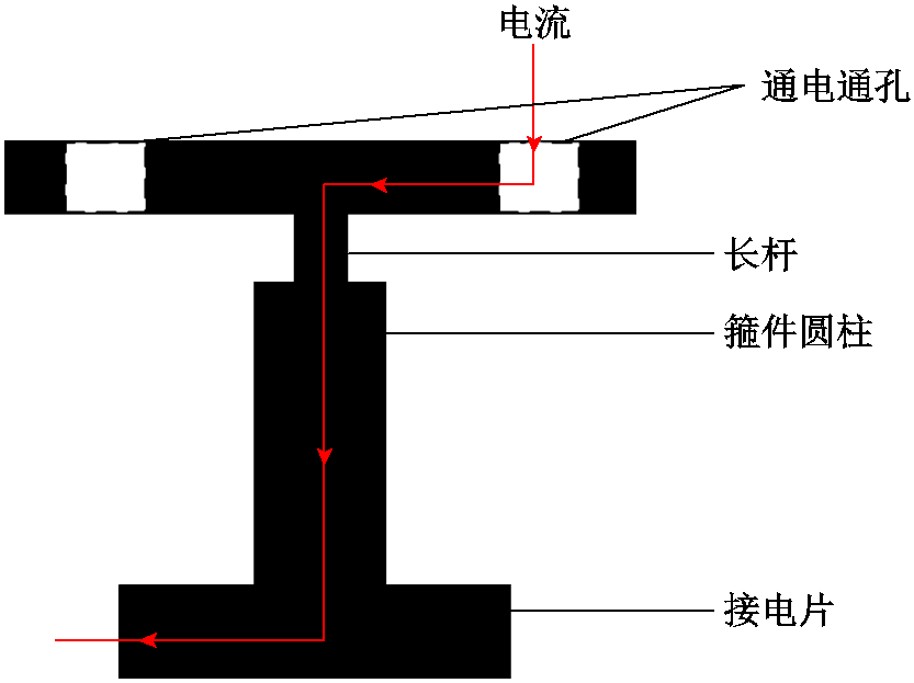
图2 长杆带箍件试样
Fig.2 Long bar with goop specimen
利用有限元仿真及理论计算可得到材料变形时应变率及电流密度[16-17]。有限元电磁仿真软件通过输入的斥力电压为1.6 kV时线圈电流计算斥力盘受到的电磁斥力,再将电磁斥力导入显示动力学有限元仿真软件,即可得到材料受到高速冲击时的应变率。本文建立了2D轴对称仿真模型,仿真结果如图3所示,在对角处和中部的应变率最高,即不考虑试样电流加载时应变率可达20 ms-1,达到了电磁发射极端环境中的应变率条件,且从对角处至中部应变率逐渐减小,表明在材料剖面不同位置变形速率不同,可能会呈现不同的微观特征。当触发试样-电流回路导通时,试样变形处于大电流环境。电流对材料的电致塑性效应是一种复合效应,主要包括热效应和非热效应。金属塑性变形本质上是位错运动,试样通入电流后,电致塑性作用于试样可能会改变试样动态变形特性,从而影响应变率。
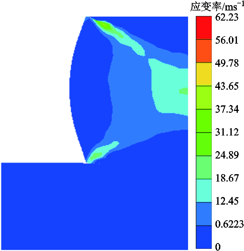
图3 剖面应变率云图
Fig.3 Strain rate contour of the section
剖面应变仿真云图如图4所示,其分布与应变率分布基本一致,在对角线及剖面中心应变最大。剖面中心应变可达0.678 80~0.763 7,对角线应变可达0.424 3~0.509 1。非剪切区域应变相对较小,主要集中在7.056×10⁻⁷~0.169 7。在对角线区域分别设置测量点1和测量点2计算两区域的剪切应力,测量结果如图5所示。对角线区域内外两点所受的剪切应力方向相反,由此在对角线区域形成剪切。对角线区域内剪切应力远大于区域外,0.20 ms时区域内剪切应力为484.26 MPa,区域外剪切应力仅为71.49 MPa。
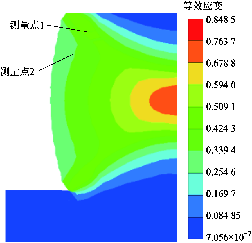
图4 剖面应变云图
Fig.4 Strain contour of the section
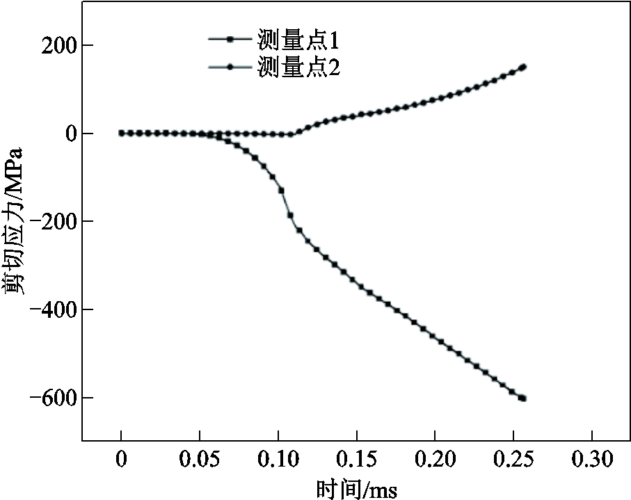
图5 剪切区域和非剪切区域的剪切应力
Fig.5 Shear stress in shear and non-shear regions
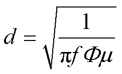
在电磁发射过程中,电枢和轨道处于大电流环境,电流密度为108~1010 A/m2。考虑到电流趋肤效应,在电枢表面电流密度更高,电流趋肤深度为
 (1)
(1)
式中,f为电流频率;Φ为电导率;μ为磁导率。实验中施加在试样上的长脉冲电流频率为627.2 Hz,2A10铝合金是弱顺磁性,在室温下的相对磁导率为1。2A10铝合金的电导率为1.8×10⁷~3.0×10⁷ S/m,计算得到趋肤深度为3.67~4.74 mm,均大于长杆宽度2.5 mm,即认为电流为均匀分布,当试样电流峰值为1 800 A时,电流密度可达3.68×10⁸ A/m2,满足电磁发射极端环境的电流密度条件。
经多次仅触发斥力回路导通实验,确定2A10铝长杆带箍件试样产生裂纹的斥力回路电容临界放电电压为1.6 kV。将斥力回路电容放电电压设置为1.6 kV,使试样在无电流条件下变形,应力波放大器和试样轴心横向偏离0.2 mm,斥力线圈电流如图6所示,电流脉宽为390 μs,幅值为6 597.36 A。对试样进行轴向切开、打磨、机械抛光及化学刻蚀处理,刻蚀剂选择Keller试剂(1 mL HF, 1.5 mL HCL, 2.5 mL HNO3及 95 mL H2O)。
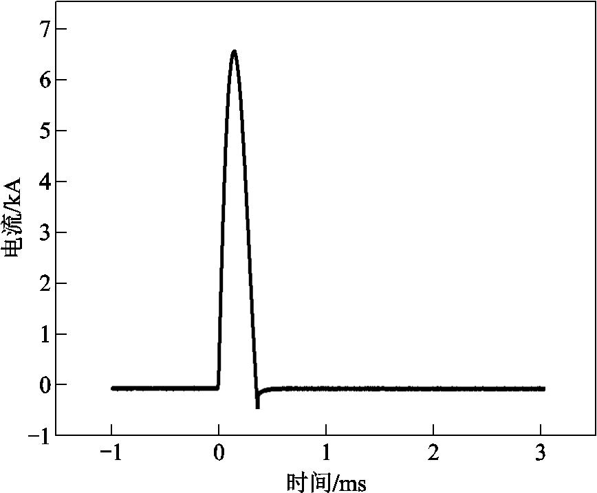
图6 线圈电流
Fig.6 Coil current
光学显微镜观测下无电流加载试样剖面如图7所示,剖面右上至左下对角线处可明显观测到绝热剪切带,两对角处均产生裂纹,越靠近中部,剪切变形越小。右上对角处至剖面中部放大观测如图8所示,由中部至对角处可同时观测到剪切变形、绝热剪切带和裂纹三种微观特征。绝热剪切带从对角处向中部宽度逐渐增大,通过标尺工具计算得到绝热剪切带的长度为1 077.4 。从中部至对角处,材料变形的剪切应力逐渐减小,从三种特征可以得到材料的微观变形过程。

图7 光学显微镜观测下无电流加载试样剖面
Fig.7 Specimen section observation without current loading under optical microscope
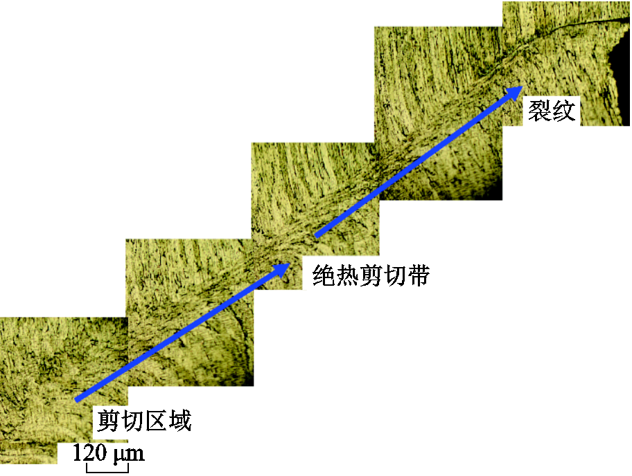
图8 光学显微镜观测下无电流加载试样右上剖面
Fig.8 Specimen upper right section without current loading under optical microscope observation
无电流加载试样绝热剪切带光学显微镜观测和扫描电镜分别如图9和图10a所示,在剪切带内能够观察到细长晶粒,表明材料在产生剪切变形时晶粒被拉长,绝热剪切带的宽度约为30 μm。如图10b所示,带内产生微孔洞,表明2A10铝合金受冲击形成韧性绝热剪切带,微孔洞经形核、生长和联接后发展为裂纹,造成绝热剪切失效。保持斥力回路电容放电电压为1.6 kV不变,试样-电流回路1自斥力回路导通延时300 μs,试样-电流回路2自斥力回路导通延时630 μs,总脉宽为1.5 ms,可保证材料受力最大时电流密度最大。进行了两组对照实验,放电参数见表2,试样电流峰值分别达到1 860 A和 5 400 A,选取试样变形时电流平均值计算电流密度,分别为3.68×10⁸ A/m2和1.02×109 A/m2,达到了电磁发射电流密度条件,电流波形如图11所示。

图9 无电流加载试样的绝热剪切带光镜观测
Fig.9 Adiabatic shear band optical microscopy observation of specimens without current loading

图10 无电流加载试样的绝热剪切带电镜观测
Fig.10 Adiabatic shear band Scanning electron microscope observation of specimens without current loading
表2 放电参数
Tab.2 Discharging parameters

线圈电流峰值/A试样电流峰值/A电流密度/(A/m2) 6 597.36—— 6 557.381 8603.68×108 6 557.385 4001.02×109
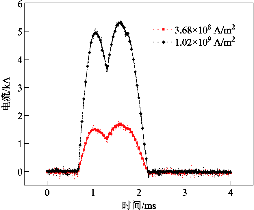
图11 试样电流
Fig.11 Specimen current
施加脉冲电流后试样剖面光学显微镜观测如图12所示,同样可观测到剪切变形、绝热剪切带和裂纹三种特征。相比于无电流加载试样,三种微观特征分布发生了变化,裂纹和绝热剪切带的长度减小,剪切变形区域长度增大。经测量可得,相同斥力条件下,无电流、电流密度为3.68×10⁸ A/m2和1.02×109 A/m2三种实验试样的对角线方向平行的裂纹长度分别为285.71、230.25和179.02 μm,施加电流后,裂纹长度分别减少了19.41%和37.34%。绝热剪切带的长度分别为1 077.4、883.09和754.74 μm,施加电流后分别降低了18.04%和29.95%。这表明在相同的斥力条件下,在材料变形的同时通入脉冲电流会导致裂纹和绝热剪切带长度变短,且随着电流密度增大,两者长度进一步变短。微裂纹的产生改变了温度分布,裂纹尖部和两侧温升不同,形成了温度梯度,裂纹承受梯度产生的压缩应力逐渐闭合。当脉冲电流周期相同时,电流幅值越高,裂纹愈合速度越快[18]。

图12 剖面微观特征
Fig.12 Microscopic characteristics of the section
目前已有大量研究表明动态再结晶是产生绝热剪切带的主要机制[19-23]。材料在剪切区域通过动态再结晶产生细小再结晶晶粒,再结晶晶粒形成软化点从而在该处形成应力集中,产生绝热剪切带。动态再结晶可分为连续动态再结晶、不连续动态再结晶和旋转动态再结晶。连续动态再结晶和不连续动态再结晶均属于迁移型动态再结晶。由于绝热剪切带的形成具有高应变率和短时间尺度特征,晶界迁移产生相应尺寸晶粒所需的时间比变形时间高几个数量级,因此迁移性动态再结晶不再适用[24]。M. A. Meyers等提出了旋转动态再结晶[25]。旋转动态再结晶产生绝热剪切带原理如图13所示,材料发生塑性变形后,位错源开动产生位错增殖,位错重新排列相互堆积产生位错胞,位错胞形核产生亚晶。亚晶界旋转与相邻晶界重合以降低界面能,因此形成等轴再结晶晶粒。材料在动态再结晶晶粒处塑性失稳产生绝热剪切带。随着塑性变形的进行,剪切带内微孔洞成核并逐渐联结,最终沿着绝热剪切带发展为裂纹。晶界旋转的动力学方程如式(2)和式(3)所示[26-27]。
 (2)
(2)
 (3)
(3)
式中,t为晶粒旋转所需时间;!为晶界厚度;″为晶界能; 为与晶界扩散相关的常数;L为亚晶界的平均长度;k为材料常数;
 为晶界扩散活化能;T为剪切带内温度;
 为玻耳兹曼常数;θ为亚晶旋转角度。亚晶的亚晶界旋转30°即可产生再结晶晶粒,相比于迁移性动态再结晶,旋转动态再结晶可以在几毫秒甚至几十微秒内完成[25,27]。
施加脉冲电流后,脉冲电流对旋转动态再结晶的作用机理如图13所示。脉冲电流主要包括热效应和电效应,其导致绝热剪切带带长减小也需要从热软化效应和电效应两方面分析:从电效应方面考虑,施加脉冲电流后,由于电子风力,即漂流电子不断撞击位错,位错缠结和位错均减少[28-29],阻碍了位错胞的形成;从热软化效应方面考虑,由于本文所采用的脉冲电流在变形部分即长杆处均匀分布,电流的热效应导致长杆部分整体软化。通过COMSOL计算试样电流温升如图14所示。电流密度为3.68×10⁸ A/m2和1.02×109 A/m2时,试样最高温升分别为2.3 K和22.7 K,温升速率分别为1.73×10³ K/s和1.65×104 K/s。从温升角度分析,脉冲电流焦耳热对试样软化效果很小,相比于其再结晶温度更是相去甚远。但是从温升速率角度考虑,脉冲电流进一步提高了材料总体温升速率,过高的温升速率使材料在各温度下停留时间过短而来不及形核[30],因此焦耳热亦阻碍了位错胞、亚晶和动态再结晶晶粒的形成。因此,随着电流密度升高,旋转动态再结晶受到抑制,局部软化点难以形成,绝热剪切带难以产生。

图13 旋转动态再结晶产生绝热剪切带原理
Fig.13 Schematic diagram of the principle of adiabatic shear band generated by rotational dynamic recrystallization
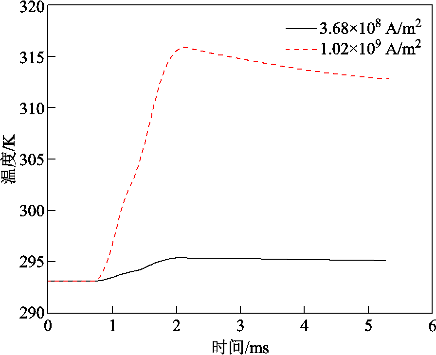
图14 试样电流产生的温升
Fig.14 Temperature rise from specimen current
本文设计了一种偏轴长杆带箍件试样构型,通过脉冲功率源和电磁斥力盘开展了极端多物理场环境下2A10铝的动态变形特性研究,在试样剖面同时观测到了剪切变形、绝热剪切带和裂纹三种微观特征。进行了不同电流密度条件下的对照实验,结论如下:
1)仿真结果、理论计算和光学显微镜试样剖面观测结果表明:2A10铝动态变形的应变率和电流密度满足了电磁发射极端多物理场条件。偏轴试样构型剖面从中部至对角处应变率逐渐增大,试样剖面同时存在剪切变形、绝热剪切带和裂纹三种微观特征,在仅触发斥力回路导通的条件下,裂纹和绝热剪切带的长度分别为285.71 μm、 1 077.4 μm。
2)随着电流密度增大,剪切变形、绝热剪切带和裂纹三种微观特征分布发生变化,裂纹和绝热剪切带的长度均减小,剪切变形区域长度增大。当电流密度为3.68×10⁸ A/m2和1.02×109 A/m2时,裂纹长度分别减小了19.41%和37.34%,绝热剪切带的长度分别减小了18.04%和29.95%。脉冲电流对裂纹和绝热剪切带均有抑制作用。
3)后续可通过EBSD、TEM等手段对绝热剪切带带内更小尺度进行观测。如检测带内组织是否发生相变。小直径(小于1 μm)的第二相粒子通过激发促进成核进而提高动态再结晶程度。检测通入电流后第二相粒子直径和体积分数是否发生变化。
4)脉冲电流对高速冲击下材料绝热剪切带的作用规律研究对电磁能材料选型和性能评估具有重要意义,为电磁能材料损伤研究提供了数据支撑。
参考文献
[1] 陈帅, 马偃亳, 赵婉瑜, 等. 电磁轨道炮最新研究进展及应用展望[J]. 科技创新与应用, 2022, 12(17): 11-14.
Chen Shuai, Ma Yanbo, Zhao Wanyu, et al. Latest research progress and application prospect of electromagnetic rail gun[J]. Technology Innovation and Application, 2022, 12(17): 11-14.
[2] 李军, 严萍, 袁伟群. 电磁轨道炮发射技术的发展与现状[J]. 高电压技术, 2014, 40(4): 1052-1064.
Li Jun, Yan Ping, Yuan Weiqun. Electromagnetic gun technology and its development[J]. High Voltage Engineering, 2014, 40(4): 1052-1064.
[3] 杜佩佩, 鲁军勇, 冯军红, 等. 电磁轨道发射器电磁结构耦合动态发射过程数值模拟[J]. 电工技术学报, 2020, 35(18): 3802-3810.
Du Peipei, Lu Junyong, Feng Junhong, et al. Numerical simulation of dynamic launching process of electromagnetic rail launcher with electromagnetic and structural coupling[J]. Transactions of China Electrotechnical Society, 2020, 35(18): 3802-3810.
[4] 马伟明, 肖飞, 聂世雄. 电磁发射系统中电力电子技术的应用与发展[J]. 电工技术学报, 2016, 31(19): 1-10.
Ma Weiming, Xiao Fei, Nie Shixiong. Applications and development of power electronics in electromagnetic launch system[J]. Transactions of China Electrotechnical Society, 2016, 31(19): 1-10.
[5] 马伟明, 鲁军勇. 电磁发射技术的研究现状与挑战[J]. 电工技术学报, 2023, 38(15): 3943-3959.
Ma Weiming, Lu Junyong. Research progress and challenges of electromagnetic launch technology[J]. Transactions of China Electrotechnical Society, 2023, 38(15): 3943-3959.
[6] 刘赛男, 孙洋洋, 翟鹏远, 等. 电磁轨道炮铜合金导轨失效研究与应对策略[J]. 兵器装备工程学报, 2022, 43(8): 87-94.
Liu Sainan, Sun Yangyang, Zhai Pengyuan, et al. Research on failure mechanism and response strategy of copper alloy guideway of electromagnetic rail gun[J]. Journal of Ordnance Equipment Engineering, 2022, 43(8): 87-94.
[7] 李建国, 豆清波, 索涛. 金属材料绝热剪切带形成机制及多尺度模拟研究进展[J]. 科学通报, 2021, 66(32): 4081-4097.
Li Jianguo, Dou Qingbo, Suo Tao. Advances in formation mechanisms and multiscale simulations of adiabatic shear bands in metallic materials[J]. Chinese Science Bulletin, 2021, 66(32): 4081-4097.
[8] Okada A, Kiritani M. Application of an electromagnetic accelerator to ultra-high-speed plastic deformation experiments[J]. Radiation Effects and Defects in Solids, 2002, 157(1/2): 157-164.
[9] 张静, 谭成文, 刘新芹, 等. Ti-6Al-4V合金绝热剪切带的演化[J]. 稀有金属, 2009, 33(5): 648-651.
Zhang Jing, Tan Chengwen, Liu Xinqin, et al. Evolution of adiabatic shear bands in typical microstructure of Ti-6Al-4V alloy[J]. Chinese Journal of Rare Metals, 2009, 33(5): 648-651.
[10] Li Dahe, Yang Yang, Xu Tiancheng, et al. Observation of the microstructure in the adiabatic shear band of 7075 aluminum alloy[J]. Materials Science and Engineering: A, 2010, 527(15): 3529-3535.
[11] Yang Yang, Jiang Feng, Zhou B M, et al. Microstructural characterization and evolution mechanism of adiabatic shear band in a near beta-Ti alloy[J]. Materials Science and Engineering: A, 2011, 528(6): 2787-2794.
[12] Dimitrov N K, Liu Yucheng, Horstemeyer M F. Electroplasticity: a review of mechanisms in electro-mechanical coupling of ductile metals[J]. Mechanics of Advanced Materials and Structures, 2022, 29(5): 705-716.
[13] Salandro W A, Bunget C, Mears L. Modeling and quantification of the electroplastic effect when bending stainless steel sheet metal[C]//ASME 2010 International Manufacturing Science and Engineering Conference, Erie, Pennsylvania, USA, 2010, 1: 581-590.
[14] Sánchez Egea A J, González Rojas H A, Celentano D J, et al. Electroplasticity-assisted bottom bending process [J]. Journal of Materials Processing Technology, 2014, 214(11): 2261-2267.
[15] Li Xia’nan, Xu Zhutian, Guo Ping, et al. Electroplasticity mechanism study based on dislocation behavior of Al6061 in tensile process[J]. Journal of Alloys and Compounds, 2022, 910: 164890.
[16] 熊奇, 朱鑫辉, 赵翔, 等. AZ31镁合金管件电磁吸引式成形动态特性研究[J]. 电工技术学报, 2023, 38(10): 2577-2588, 2636.
Xiong Qi, Zhu Xinhui, Zhao Xiang, et al. Research of dynamic characteristics in electromagnetic attraction forming of AZ31 magnesium alloy tube[J]. Transactions of China Electrotechnical Society, 2023, 38(10): 2577-2588, 2636.
[17] 邱立, 余一杰, 聂小鹏, 等. 管件电磁胀形过程中的材料变形性能问题与电磁力加载方案[J]. 电工技术学报, 2019, 34(2): 212-218.
Qiu Li, Yu Yijie, Nie Xiaopeng, et al. Study on material deformation performance and electromagnetic force loading in electromagnetic tube expansion process[J]. Transactions of China Electrotechnical Society, 2019, 34(2): 212-218.
[18] 王忠金, 宋辉, 蔡舒鹏, 等. 脉冲电流诱导钛合金板材裂纹愈合与组织演变研究进展[J]. 塑性工程学报, 2019, 26(2): 1-14.
Wang Zhongjin, Song Hui, Cai Shupeng, et al. Research advancements on self-healing of cracks and evolution of microstructures of titanium alloy sheets induced by electropulsing[J]. Journal of Plasticity Engineering, 2019, 26(2): 1-14.
[19] Hines J A, Vecchio K S. Recrystallization kinetics within adiabatic shear bands[J]. Acta Materialia, 1997, 45(2): 635-649.
[20] Chen Wei, Zhang Huan, Mu Juan, et al. Effects of microstructure and strain rate on dynamic mechanical properties and adiabatic shear band of TC4 alloy[J]. Acta Metallurgica Sinica, 2022, 58(10): 1-13.
[21] Eskandari M, Mohtadi-Bonab M A, Zarei-Hanzaki A, et al. High-resolution EBSD study of adiabatic shear band and neighboring grains after dynamic impact loading of Mn-steel used in vehicle structure[J]. Journal of Materials Engineering and Performance, 2016, 25(4): 1611-1620.
[22] Meyers M A, Nesterenko V F, LaSalvia J C, et al. Shear localization in dynamic deformation of materials: microstructural evolution and self-organization[J]. Materials Science and Engineering: A, 2001, 317(1): 204-225.
[23] Zhen Liang, Zou Dongli, Xu Chengyan, et al. Microstructure evolution of adiabatic shear bands in AM60B magnesium alloy under ballistic impact[J]. Materials Science and Engineering: A, 2010, 527(21/22): 5728-5733.
[24] Zhang Weiliang, He Liangju, Lu Zhigang, et al. Microstructural characteristics and formation mechanism of adiabatic shear bands in Al-Zn-Mg-Cu alloy under dynamic shear loading[J]. Materials Science and Engineering: A, 2020, 791: 139430.
[25] Meyers M A, Xu Yongbo, Xue Qing, et al. Microstructural evolution in adiabatic shear locali-zation in stainless steel[J]. Acta Materialia, 2003, 51(5): 1307-1325.
[26] Yang Yang, Wang Bingfeng. Dynamic recrystallization in adiabatic shear band in α-titanium[J]. Materials Letters, 2006, 60(17/18): 2198-2202.
[27] Xiao Ang, Huang Changqing, Cui Xiaohui, et al. Impact of the pulse induced current on the microstructure and mechanical properties of the 7075-T6 aluminum alloy[J]. Journal of Alloys and Compounds, 2022, 911: 165021.
[28] Wang Shipeng, Xiao Ang, Lin Yuhong, et al. Impact of the pulse induced current on the microstructure and mechanical properties of the 7075-T6 aluminum alloy[J]. Journal of Alloys and Compounds, 2022, 911: 165021.
[29] Wang Shipeng, Xiao Ang, Lin Yuhong, et al. Effect of induced pulse current on mechanical properties and microstructure of rolled 5052 aluminum alloy[J]. Materials Characterization, 2022, 185: 111757.
[30] 胡赓祥, 蔡珣, 戎咏华. 材料科学基础[M]. 3版. 上海: 上海交通大学出版社, 2010.
Effect of Pulse Current on Adiabatic Shear Band of 2A10 Aluminum Alloy under High Speed Impact
Abstract During the electromagnetic launch process, the armature and rail are in an extreme multi-physical field environment. Due to rail vibration and uneven forces, the armature and rail generate ultra-high speed impact to form shear. However, melting and ablation caused by current result in the loss of the surface material characterization information. Therefore, it is difficult to carry out the mechanism of extreme multi-physical field on the material, which restricts the application of the material in the environment of ultra-high-speed impact and even electromagnetic launch. In order to address this problem, this paper designs the off-axis long bar with hoop specimen, and investigates the dynamic deformation characterization of 2A10 aluminum alloy under extreme multi-physical field environment, i.e., the current density of 108~109 A/m2 and the strain rate greater than or equal to 104/s. Comparing the distribution of microscopic features under different experiment conditions, and the effect of pulse current under the extreme multi-physical field conditions on dynamic deformation of the material is obtained.
A pulse power supply and an electromagnetic repulsive device are adopted to equivalently simulate the extreme multi-physical field environment of electromagnetic launch. The electromagnetic repulsive device is used to generate a high strain rate in the specimen by generating an instantaneous (390 μs) Lorentz force. While the specimen is deformed at high speed, pulse current is injected at a suitable moment to realize the electro-thermal coupling. After the experiment, the specimens are axially cut, mechanical polished, and chemically etched. The microscopic features of the specimen profile are observed by optical microscope and scanning electron microscope.
The simulation results show that the strain rate is the highest at the diagonal and in the middle, and the strain rate can be up to 2×10⁴/s. Different deformation rates at different locations of the material profile, and the gradual decrease of the strain rate from the diagonal to the middle, may present different microscopic features. The strain distribution and strain rate distribution are basically the same. The shear stresses applied to the two points inside and outside the diagonal region are in opposite directions, thus forming shear in the diagonal region. The shear stress in the diagonal region is 3~4 times larger than that outside the region. Through the calculation of skinning depth, it is known that the pulse current is uniformly distributed in the long bar of the specimen, and the pulse current applied in the experiment satisfies the current density condition.
The critical value of crack repulsion generated on the specimen surface is determined through several experiments, and this value is kept constant as the repulsion value. The experimental results of microscopic characterization of the specimen profile show that the adiabatic shear band can be clearly observed at the diagonal of the specimen profile without current, and cracks are generated at both diagonals, and the experimental observation results correspond to the simulation results. Selecting the appropriate moment to energize the pulse current, and the current densities were 3.68×10⁸ A/m2 and 1.02×10⁹ A/m2, respectively. The experimental results show that: (1) Under the same repulsive condition, the temperature gradient generated by the pulse current at the tip and both sides of the cracks healed the cracks. The crack lengths were reduced by 19.41% and 37.34%, respectively. (2) The pulse current suppressed the rotational dynamic recrystallization through the effects of electron wind and Joule heat, etc. The dynamic recrystallization grains were reduced and it was difficult to form the softening point inside the material, which suppressed the formation of adiabatic shear band. The lengths of adiabatic shear bands were reduced by 18.04% and 29.95%, respectively.
keywords:High speed impact, current density, adiabatic shear band, crack
中图分类号:TM89
DOI: 10.19595/j.cnki.1000-6753.tces.231389
国家自然科学基金项目(92066207, 92166109)和电力设备电气绝缘国家重点实验室项目(EIPE23401)资助。
收稿日期 2023-08-25
改稿日期 2023-10-17
胡前程 男,1999年生,硕士研究生,研究方向脉冲功率放电和等离子体。
E-mail:3121104074@stu.xjtu.edu.cn
陈 立 男,1983年生,副研究员,硕士生导师,研究方向为高电压与大电流、脉冲功率与放电等离子体。
E-mail:lichen29@xjtu.edu.cn(通信作者)
(编辑 赫 蕾)