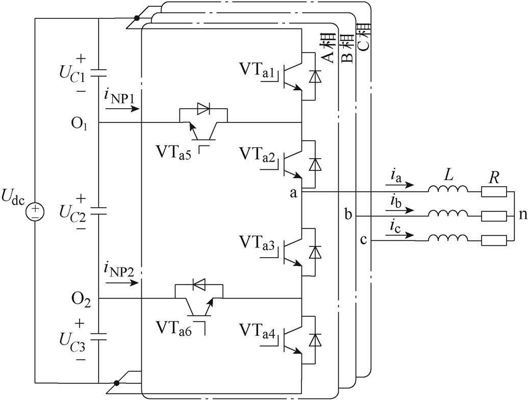
图1 4L-ANPC逆变器拓扑
Fig.1 Schematic of active four-level neutral point clamped converter
摘要 多电平有源中点钳位(ANPC)逆变器具有功率器件电压应力小、电流谐波低和器件损耗可调控等优点,被广泛应用于工业驱动中。针对四电平ANPC(4L-ANPC)逆变器的控制与调制研究相对较少,现有的调制方案实现复杂,中点电压(NPV)控制难度较大。因此,该文针对三相4L-ANPC逆变器,提出一种改进的有限集模型预测电流控制(FS-MPCC)算法,避免了复杂的调制过程。首先,使用仅包含电流误差的代价函数对位于六边形顶点的6个大电压矢量进行寻优;其次,对参与第一步寻优的大矢量划分扇区,使用包含电流误差和电容电压误差的代价函数对最优大矢量所在扇区的所有电压矢量滚动寻优,得到目标电压矢量并作用于逆变器;最后,仿真和实验结果表明,与传统的FS-MPCC相比,所提方法在降低系统计算负担的同时,还具有较好的控制性能和电容电压平衡能力。
关键词:四电平 有源中点钳位逆变器 有限集模型预测电流控制 电容电压平衡 代价函数
多电平DC-AC逆变器由于器件承受电压应力小、电流谐波含量低,越来越多地应用于并网可再生能源系统和电机驱动中[1-5]。与级联H桥多电平逆变器相比,有源中点钳位(Active Neutral Point Clamped, ANPC)逆变器不需要使用多个独立的直流电源,并且采用了较少数量的功率半导体。因此,它在低中压应用中更具成本优势[6-10]。此外,相比基于二极管的无源中性点钳位逆变器,ANPC逆变器可以更好地在功率半导体之间分配功率损耗,具有更高的可靠性[11]。
近年来,关于多电平ANPC逆变器的控制与调制的研究论文较多[12-18]。然而,这些方法都是针对三电平和五电平ANPC逆变器提出的,由于电路结构和直流电容数量的不同,这些控制方法不能直接应用于四电平ANPC(Four-Level ANPC, 4L-ANPC)逆变器。4L-ANPC逆变器是填补三电平和五电平逆变器空白的重要拓扑,4L-ANPC逆变器拓扑如图1所示。与三电平ANPC逆变器相比,4L-ANPC逆变器可在不增加功率器件的前提下多提供一个电压电平,使得输出电流谐波含量更小,此外,4L-ANPC逆变器还有效地降低了电路中有源开关的断态电压上升率[19];而相比于五电平ANPC逆变器,4L-ANPC逆变器所需开关元件更少,不需控制悬浮电容电压,因此减少了电压传感器的数量,降低了控制的复杂性[20-23]。

图1 4L-ANPC逆变器拓扑
Fig.1 Schematic of active four-level neutral point clamped converter
文献[24]针对一种4L-ANPC逆变器,采用具有44个选定电压矢量的空间电压矢量调制策略,虽然显著地降低了共模电压,但是其采用辅助电路平衡电容电压,造成了额外的硬件成本,并且在调制度为1时的功率损耗较大。文献[25]提出了图1所示的4L-ANPC逆变器拓扑,并采用了空间矢量脉宽调制(Space Vector Pulse Width Modulation, SVPWM)和载波调制方案,其中,由于四电平具有64个开关状态,使用SVPWM策略合成矢量实现比较复杂,且为了实现电容电压的平衡,需要研究开关状态的组合,实现难度较高。此外,上述两种调制方法并不能有效地平衡高功率因数或三相不平衡负载的电容电压。文献[26]针对背靠背p 型4L-ANPC逆变器(与图1所示的4L-ANPC逆变器不同),从拓扑、效率和控制的角度进行了分析,采用基于载波调制和动态最优零序信号注入对逆变器进行调制并控制直流电容电压平衡,降低了谐波含量和开关损耗,控制了中点电压,但是这种方法只有在5 kHz以上的高开关频率才会比两电平和三电平逆变器更有应用价值,不适合较低开关频率的应用。文献[27]针对p 型4L-ANPC逆变器,在闭环条件下使用基于载波调制的策略,利用冗余电平调制的方法实现了全工况的电容电压平衡,但是这种方法在增加开关切换的同时,增加了开关损耗,这在中高压、大功率应用场景下是不利的。文献[28]针对一种四电平混合钳位逆变器,提出一种基于载波重叠脉宽调制的方法,使用零序电压注入平衡了上下直流电容,而使用微调占空比的方法平衡了中间直流电容电压,尽管实现了全调制度、全功率因数范围内的电容电压平衡,但是其中点控制分为了两个步骤,增加了载波调制的难度和实现的复杂度。文献[29]针对一种四电平中点钳位型(Neutral Point Clamped, NPC)逆变器,提出一种满足伏秒平衡原理的载波重叠脉宽调制(Pulse Width Modulation, PWM)方法,实现了中心直流电容载波周期平衡,上下直流电容基波周期平衡,但是这种方法会受负载电流谐波影响,导致其在闭环状态下的性能不佳。文献[25-29]不可避免地使用了基于载波调制的方法,这种方法虽然具有原理简单和实现方式容易的优点,但是其不能充分利用直流电压,开关损耗较大。此外,为了实现直流电容电压的平衡,需要注入零序分量,当系统的调制度和功率因数在一定范围内时,该方法不会产生低频波动,但是此范围外的中点电压可能会产生三倍频波动。而有限集模型预测控制(Finite Set Model Predictive Control, FS-MPC)是一种能够消除调制过程的控制方法,近年来在工业上得到了广泛的应用。与其他控制方法不同的是,FS-MPC易于理解和实现,可以处理非线性,并且可以综合控制多个变量,动态选择最优电压矢量,使控制代价函数最小,然后将该电压矢量应用于逆变器,保证系统高稳态性能和快速动态响应[30-32]。传统的FS-MPC算法的主要问题是由于代价函数中所有电压矢量需迭代求值,计算量大。对于具有大量电压矢量的多电平逆变器,这一问题比较突出。文献[20]提出一种基于模型预测电流控制的方法,采用综合评估电流误差和电容电压波动的方式控制电流和中点电压,通过判断调制度大小,缩小备选矢量的选择范围。这种方式虽然有效地控制了电流和中点电压,但是其仅减少了12个备选矢量,相比4L-ANPC的全部64个开关状态而言,系统计算量的降低仍有较大优化潜力。为了减轻传统的FS-MPC的计算负担,针对三电平ANPC逆变器,文献[33]提出了一种采用级联代价函数的两级FS-MPC,然而,由于电容电压平衡的难度越来越大,因此其矢量选择机制并不直接适用于4L-ANPC逆变器。
为了有效控制4L-ANPC逆变器,本文提出一种改进的有限集模式预测电流控制(Finite Set Model Predictive Current Control, FS-MPCC)算法,采用一种改进的电压矢量选择机制,充分利用了4L-ANPC逆变器的特点,在实现优良控制性能的同时保证了电容电压的平衡。仿真和实验结果验证了本文所提算法的可行性。
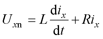
图1为4L-ANPC逆变器拓扑,其在三相坐标系下的电压电流方程可以表示为
 (1)
(1)
式中,Uxn(x=a, b, c)为x相的输出电压;ix为x相输出电流;L为负载电感;R为负载电阻。
假设电容电压可被控制到直流母线电压Udc的1/3,则逆变器每相桥臂可以产生相对于中点的4个电平,分别为Udc、2Udc/3、Udc/3和0。逆变器共产生64个开关状态,四电平空间电压矢量如图2所示。图2中,3、2、1及0分别代表逆变器输出电平Udc、2Udc/3、Udc/3和0,逆变器开关状态见表1。
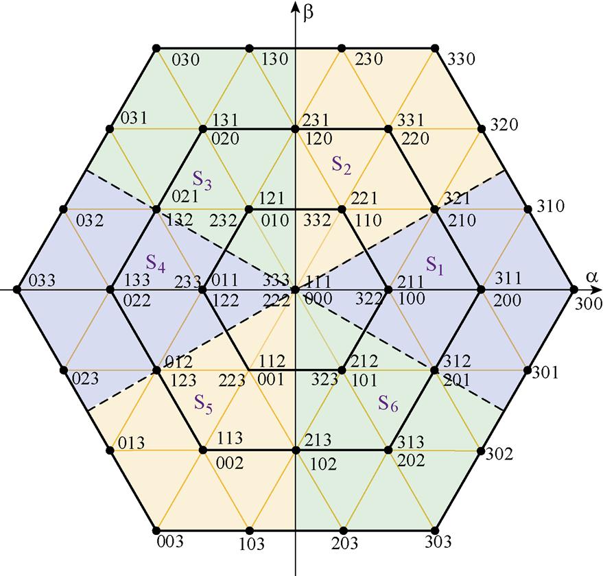
图2 四电平空间电压矢量
Fig.2 Space vector diagram for the four-level
表1 逆变器开关状态
Tab.1 Switching states of the inverter
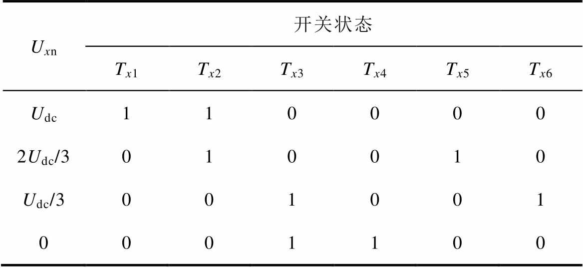
Uxn开关状态 Tx1Tx2Tx3Tx4Tx5Tx6 Udc110000 2Udc/3010010 Udc/3001001 0001100
4L-ANPC逆变器的每相开关函数表示为
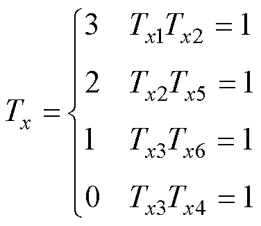 (2)
(2)
逆变器交流侧电压可以用开关函数和直流电压表示为
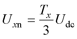 (3)
(3)
逆变器输出电压为
 (4)
(4)
对式(1)进行前向欧拉,则k+1采样时刻的预测电流为
 (5)
(5)
式中,Ts为采样周期。
逆变器一共有64种开关状态,对应37种电压矢量(36个有效电压矢量和1个零电压矢量)。电压矢量类型见表2,36个有效电压矢量可以划分为三类:大电压矢量(Large Voltage Vector, LVV)、中等电压矢量(Medium Voltage Vector, MVV)和小电压矢量(Small Voltage Vector, SVV)。
表2 电压矢量类型
Tab.2 Voltage vectors categories
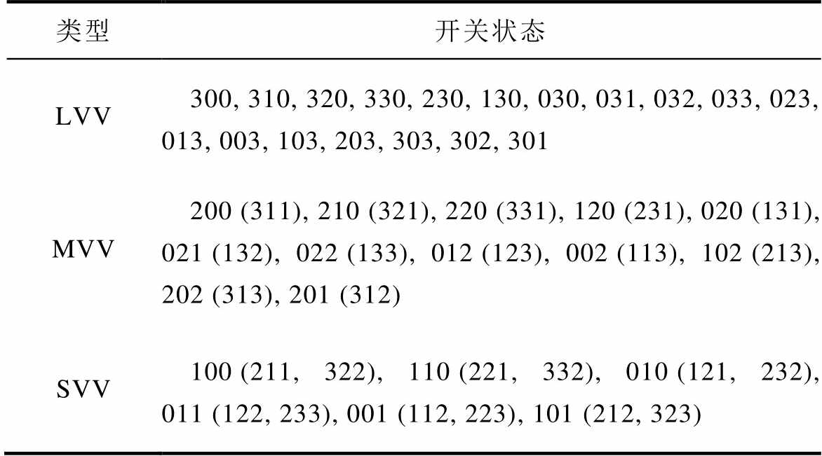
类型开关状态 LVV300, 310, 320, 330, 230, 130, 030, 031, 032, 033, 023, 013, 003, 103, 203, 303, 302, 301 MVV200 (311), 210 (321), 220 (331), 120 (231), 020 (131), 021 (132), 022 (133), 012 (123), 002 (113), 102 (213), 202 (313), 201 (312) SVV100 (211, 322), 110 (221, 332), 010 (121, 232), 011 (122, 233), 001 (112, 223), 101 (212, 323)
如图1所示,当逆变器输出电平为2Udc/3和Udc/3时,负载电流分别从中点O1和O2流出。因此,在一个采样周期中的中点(Neutral Point, NP)电流可以表示为
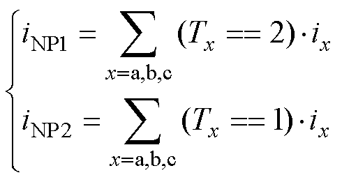 (6)
(6)
式中,iNP1和iNP2分别为中点O1和O2的输出电流。假设直流电容容值相同,即均为Cd,则直流电容之间的NP电流的分布如图3所示。MVV和SVV具有冗余的电压矢量,冗余矢量之间输出电压相同,但对NPV的影响不同。例如,010、121和232都属于SVV,能够输出同样的电压矢量,但从图3和式(6)可以看出,三种开关状态产生不同的NP电流。
NP电流和电容电压变化量的关系可表示为式(7),将式(7)离散化可以得到式(8)。式(8)表明,三个直流电容电压与两个NP电流相关。在理想的稳态条件下,基于载波的PWM方法可以实现三个直流电容电压的平衡,但是此方法受限于逆变电路的完善程度和动态响应[29],因此,需要采用闭环控制保证电容电压平衡。
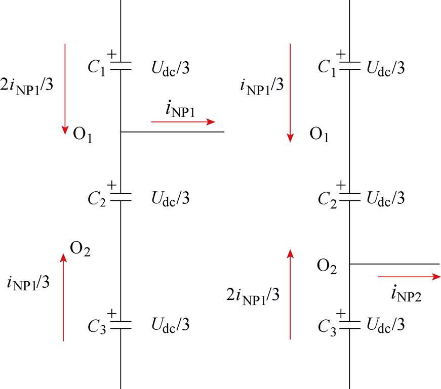
图3 NP电流对直流电容电压的影响
Fig.3 Influences of NP currents on the DC-link capacitor voltages
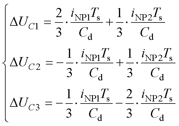 (7)
(7)
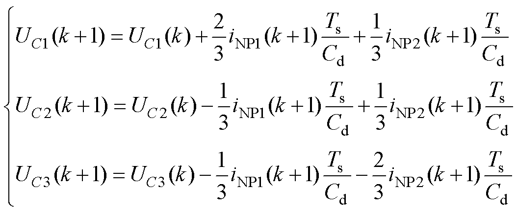 (8)
(8)
为了追踪参考电流并且控制电容电压,传统FS- MPCC的代价函数为
 (9)
(9)
式中,ix(k+1)为三相负载电流预测值; 为参考电流;ldc为电容电压误差项的权重系数;DUC为预测电容电压和其标称值的差值,即
 (10)
(10)
相比于两电平和三电平逆变器,四电平电压矢量较多,而传统MPCC采用64种开关状态进行滚动寻优,这将增大控制器的计算量和计算负担。因此,本文提出一种改进的FS-MPCC算法以减小计算量。
改进的FS-MPCC的控制流程如图4所示。对六边形顶点处的6个LVV进行评估,找出使得式(11)中的代价函数g1最小的最优LVV。如图2所示,电压矢量可以划分为6个小扇区,小扇区所占区域为包括LVV在内的±30°区域。当选择出最优的LVV后,使用式(12)确定小扇区,将该小扇区内所有的电压矢量代入式(13)的代价函数g2进行评估,选择出目标电压矢量作用于逆变器。

图4 改进FS-MPCC的控制流程
Fig.4 Control diagram of the improved FS-MPCC
将位于最外层六边形顶点的6个LVV(300, 330, 030, 033, 003, 303)作为控制集。LVV不影响NP,因此第一阶段的代价函数不考虑电容电压误差,即
 (11)
(11)
根据式(11)可以确定最优LVV。然后,将电压矢量划分为如图2所示的6个扇区,根据式(12)确定最优LVV所在扇区,其中,SN表示扇区编号,N=1,…, 6。扇区S1的空间电压矢量如图5所示,当最优LVV为300时,其所在扇区为S1,扇区范围为-p/6≤S1≤p/6。
 (12)
(12)
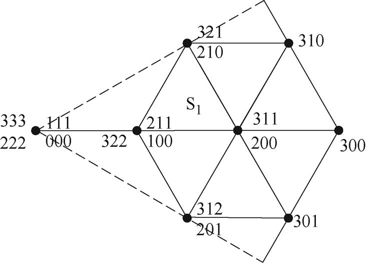
图5 扇区S1的空间电压矢量
Fig.5 Space vector diagram of sector S1
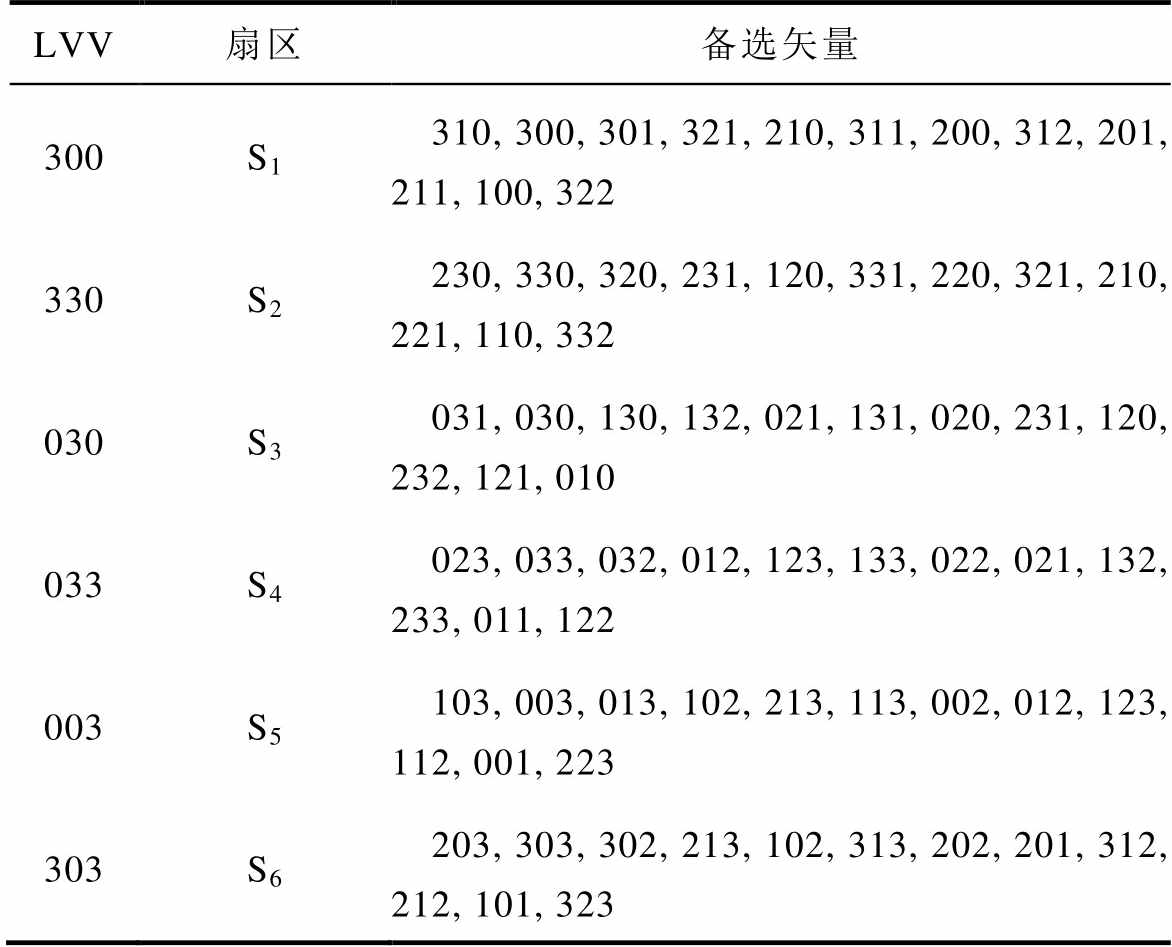
通过式(12)获得最优LVV所在扇区后,扇区内所有电压矢量将参与第二阶段代价函数的寻优,第二阶段备选电压矢量见表3。由于每个扇区包括3个LVV开关状态、6个MVV开关状态、3个SVV开关状态及1个零矢量开关状态,并且MVV和SVV对NP有影响,因此第二阶段的代价函数在评估电流误差的同时还需考虑电容电压误差,表示为
 (13)
(13)
表3 每个扇区的候选开关状态(不包括零电压矢量)
Tab.3 Candidate switching states set in each sector (not include zero voltage vector)
LVV扇区备选矢量 300S1310, 300, 301, 321, 210, 311, 200, 312, 201, 211, 100, 322 330S2230, 330, 320, 231, 120, 331, 220, 321, 210, 221, 110, 332 030S3031, 030, 130, 132, 021, 131, 020, 231, 120, 232, 121, 010 033S4023, 033, 032, 012, 123, 133, 022, 021, 132, 233, 011, 122 003S5103, 003, 013, 102, 213, 113, 002, 012, 123, 112, 001, 223 303S6203, 303, 302, 213, 102, 313, 202, 201, 312, 212, 101, 323
然后,输出使式(13)最小的电压矢量作为目标电压矢量,作用于逆变器。
图6为所提出的改进FS-MPCC的算法流程,步骤如下:
(1)测量负载电流ix(k)和3个直流电容电压UC1(k)、UC2(k)及UC3(k)。
(2)式(5)计算k+1时刻的负载电流ix(k+1);式(8)计算k+1时刻的直流电容电压UC1(k+1)、UC2(k+1)及UC3(k+1)。
(3)式(11)对6个位于最外层六边形顶点的LVV滚动寻优。
(4)判断最优LVV所在的扇区。
(5)式(13)对最优LVV所在扇区的所有电压矢量滚动寻优,得到目标电压矢量。
(6)输出目标电压矢量。
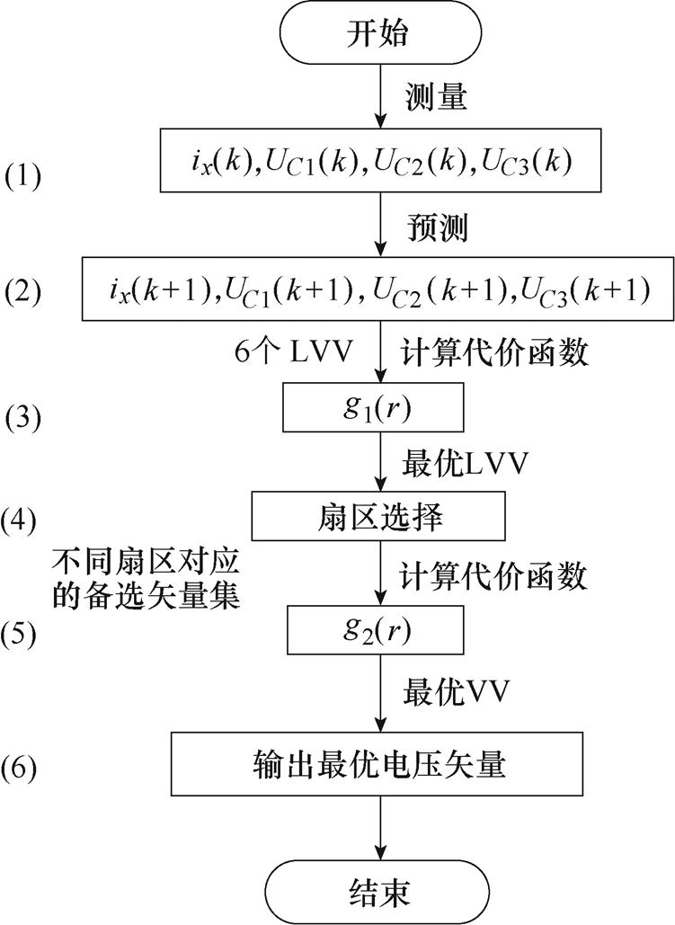
图6 所提FS-MPCC的流程
Fig.6 Flow chart of improved MPCC for a four-level inverter
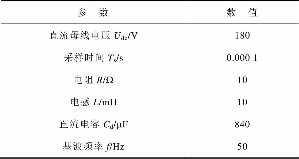
在Matlab/Simulink环境中对所提出的FS-MPCC进行验证。仿真参数见表4。
表4 系统参数
Tab.4 Parameters of system
参 数数 值 直流母线电压Udc/V180 采样时间Ts/s0.000 1 电阻R/W10 电感L/mH10 直流电容Cd/mF840 基波频率f/Hz50
首先,本文验证了所提出的FS-MPCC的稳态性能。图7为不同负载电流下的仿真波形。图8为不同输出频率下的仿真波形,从上到下分别表示相电流,输出线电压Uab,电容电压UC1、UC2和UC3。图中,Iref为参考电流幅值。由图7、图8的结果,可以总结如下:
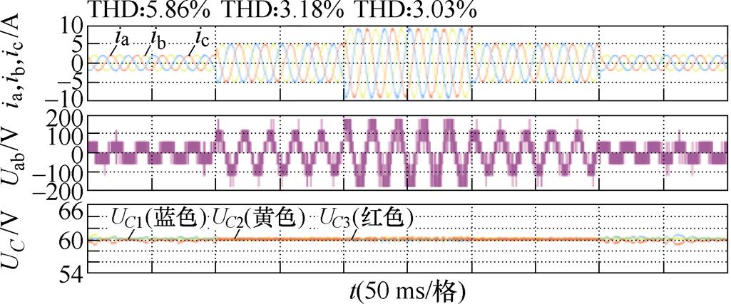
图7 所提FS-MPCC在不同参考电流下的仿真波形(2 A, 5 A, 9 A)
Fig.7 Simulation waveforms with proposed FS-MPCC at different reference currents (2 A, 5 A, 9 A)
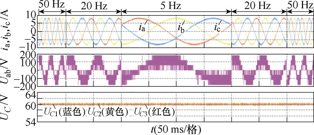
图8 所提FS-MPCC在不同基波频率下的仿真波形(Iref =9 A)
Fig.8 Simulation waveforms with proposed FS-MPCC at various fundamental frequencies (Iref =9 A)
(1)在不同的仿真条件下,所提方法的输出电流都是高质量的正弦电流。如图7所示,不同参考电流下的输出电流总谐波畸变率(Total Harmonic Distortion, THD)分别为5.86%、3.18%和3.03%。其中,当参考电流为2 A时,输出电流的THD值较高,为5.86%,这是由于此时的调制度较低引起的,这在DC-AC逆变器中较为常见[26]。
(2)如图7所示,输出线电压在不同输出电流下具有不同的电平(即不同的调制度)。
(3)如图7、图8所示,由于代价函数g2加入了电容电压误差项,选择得到的目标电压矢量考虑了NPV的波动,因此保证了电容电压的平衡。由此可见,本文所提算法在不同调制度和不同基波频率下的直流电容电压均能够较好地平衡在其参考电压(60 V)附近,且峰对峰纹波保持在2 V(小于电容标称电压的3.5%)。
综上所述,本文提出的FS-MPCC在不同负载电流和频率下均具有良好的稳态性能。
图9~图11分别为不同工况下的动态响应波形。可以得到:
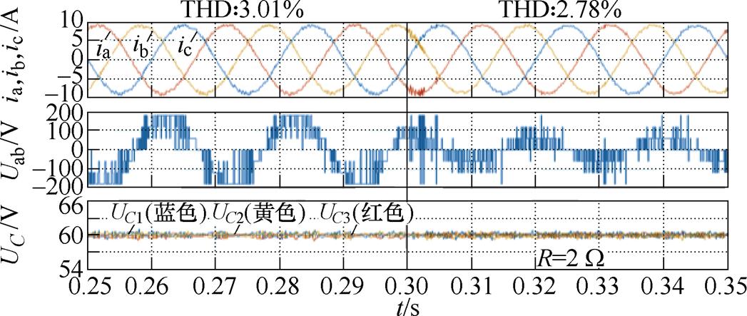
图9 负载在0.30 s突变时所提FS-MPCC的仿真波形(Iref =9 A)
Fig.9 Simulation waveforms with proposed FS-MPCC when load changed at 0.30 s (Iref =9 A)
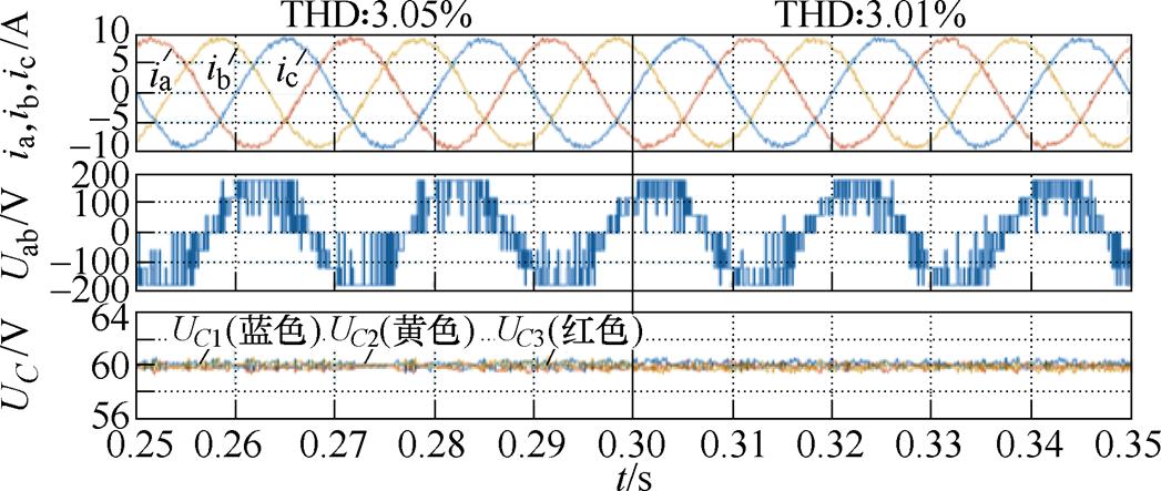
图10 直流电容0.30 s并联电阻时所提FS-MPCC的仿真波形(Iref =9 A)
Fig.10 Simulation waveforms with proposed FS-MPCC when resistors are purposely added in parallel to DC-link capacitors at 0.30 s (Iref =9 A)
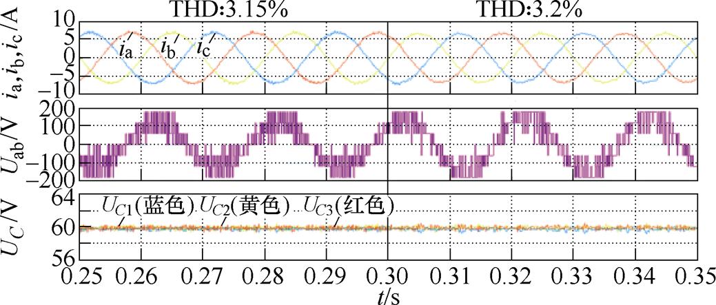
图11 参数在0.30 s突变时所提FS-MPCC仿真波形(Iref =7 A)
Fig.11 Simulation waveforms with proposed FS-MPCC when parameters changed at 0.30 s (Iref =7 A)
(1)如图9所示,参考电流为9 A,当负载电阻由10 W 突变为2 W 时,输出电流能较快地跟踪参考电流,电容电压平衡较好,输出电流和电容电压无大峰值,在0.30 s突变时刻过渡平滑。此外,负载电阻突变后,调制度变小,因此线电压电平数相应减少。
(2)如图10所示,在直流电容上并联电阻,对所提策略控制NPV的能力进行验证。可以发现,0.30 s并联电阻后,输出电流谐波没有增加,NPV波动基本不变。
(3)如图11所示,R和L在0.30 s时增加到原值的130%,可以看出,输出电流THD和NPV波动在参数突变前后几乎不变。由此可见,所提方法具有较强的参数鲁棒性。
搭建如图12所示的硬件电路对所提算法进行实验验证,实验参数与仿真一致,见表4。采用dSPACE DS1007数字处理器板卡实现数字控制,采用DS5203 FPGA板卡生成各开关的门极驱动信号,实现数模信号之间的转换。该逆变器由三个绝缘栅双极型晶体管(Insulated-Gate Bipolar Transistors, IGBTs)功率模块(Infineon_FF50R12RT4)实现。使用型号为Tektronix MSO54的数字示波器观察实验波形。实验设置见表5。
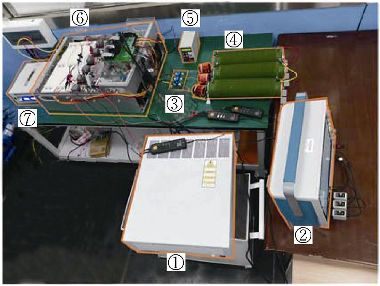
图12 4L-ANPC逆变器实验平台
Fig.12 Experimental platform of the 4L-ANPC inverter
①—dSPACE ②—示波器 ③—阻感负载 ④—电流传感器 ⑤—控制电源 ⑥—4L-ANPC逆变器 ⑦—直流电源
表5 实验设置
Tab.5 Experimental cases
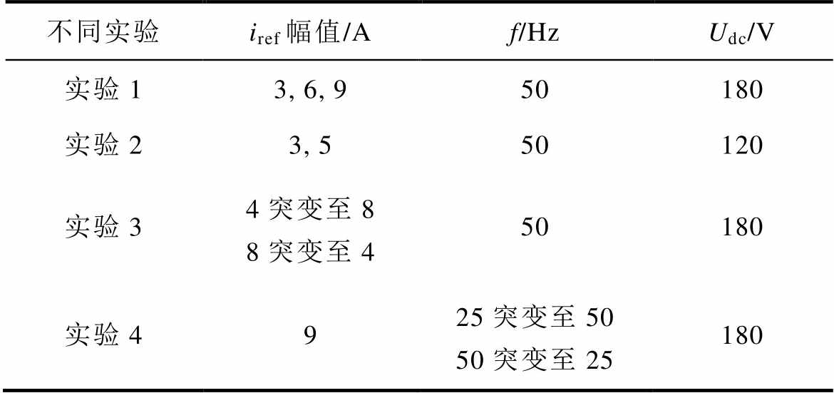
不同实验iref幅值/Af/HzUdc/V 实验13, 6, 950180 实验23, 550120 实验34突变至88突变至450180 实验4925突变至5050突变至25180
此外,与传统的FS-MPCC进行对比。定义两种算法分别为FS-MPCC-Ⅰ和FS-MPCC-Ⅱ:FS- MPCC-Ⅰ为传统的FS-MPCC,在其代价函数中评估四电平逆变器的全部64个电压矢量;FS-MPCC-Ⅱ为提出的改进FS-MPCC,仅评估19个电压矢量(g1评估6个LVV,g2评估12个有效电压矢量和1个零电压矢量)。
计算负担是FS-MPCC重点关注问题之一。使用dSPACE配置文件对FS-MPCC-Ⅰ和FS-MPCC-Ⅱ的执行时间分别进行测试,FS-MPCC-Ⅰ所需的时间为24.48 ms,而FS-MPCC-Ⅱ所需的时间仅为21.63 ms。由于其有两个处理器核心,处理器速率为2 GHz,并且具有更大的缓存存储器,处理器DS1007提供的计算能力比TI的DSP TMS320F28377高10倍。测试结果表明,FS-MPCC-Ⅱ计算量比FS-MPCC-Ⅰ方法减少了11.6%左右,具有较高的计算效率。
在不同直流电压下、不同参考电流下比较FS- MPCC-Ⅰ和FS-MPCC-Ⅱ的稳态性能,如图13~图16所示。可以得出以下结论。
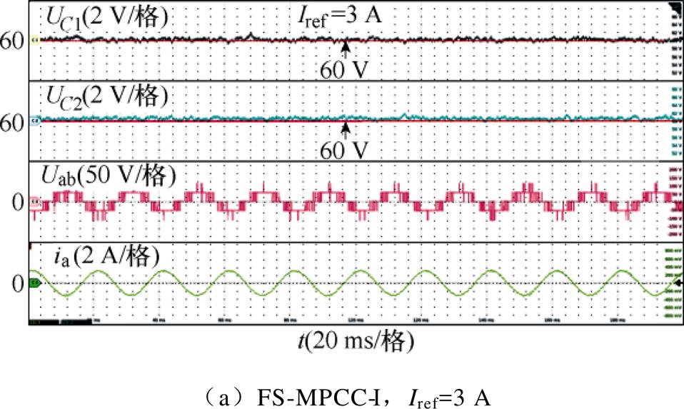

图13 实验1下的直流电容电压UC1、UC2、线电压Uab和电流ia的实验结果
Fig.13 Experimental results of DC-link capacitors voltage UC1, UC2, line voltage Uab and current ia in Experimental 1
(1)如图13所示,两种方法均能在较宽调制度范围内有效控制NPV,使电容电压峰间纹波小于4 V(即约为电容额定电压60 V的6.67%)。由式(6)和式(7)可知,通过电容的负载电流在一个控制周期内增大,因此NPV略有增大。
(2)如图13、图14所示,随着参考电流的增大,两种方法的线电压电平数增加,输出电流谐波含量降低;两种方法在同一参考电流时的输出电流谐波相似。
(3)如图15、图16所示,验证了FS-MPCC-Ⅱ在不同直流电压下的稳态控制性能,可以看出,FS-MPCC-Ⅱ的输出电流谐波较低且具有良好的电容电压平衡能力。
综上所述,与FS-MPCC-Ⅰ相比,FS-MPCC-Ⅱ在降低计算量的同时保证了稳态性能。
对FS-MPCC-Ⅱ的动态性能进行验证,如图17、图18所示。图17为参考电流突变时的验证结果。图18为参考电流频率变化时的验证结果。由图17、图18可以看出,在不同调制度和不同基波频率下,电容电压保持平衡,且在突变前后过渡平稳,表明FS-MPCC-Ⅱ具有较好的NPV控制效果。此外,当参考电流幅值和频率变化50%时,输出电流能快速跟踪参考电流,响应时间约为1 ms,表明FS-MPCC- Ⅱ具有较快动态响应。
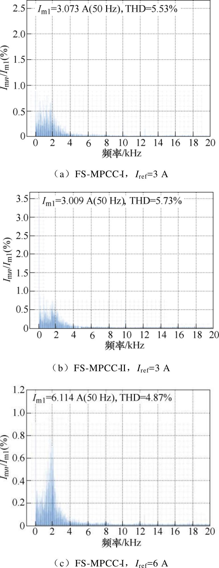
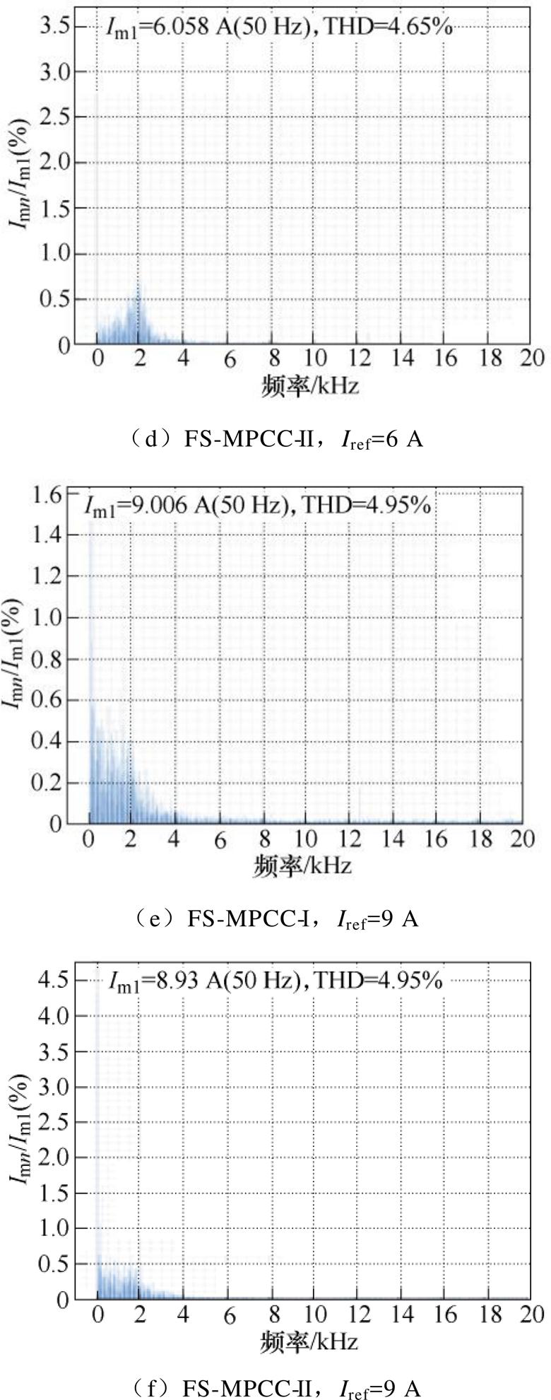
图14 实验1输出电流的快速傅里叶变换分析结果
Fig.14 Fast Fourier transform of output current in Experimental 1
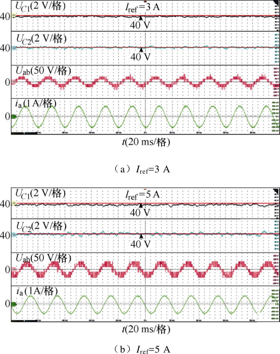
图15 FS-MPCC-Ⅱ在实验2下的直流电容电压UC1、UC2、线电压Uab和电流ia的实验结果
Fig.15 Experimental results of DC-link capacitors voltage UC1, UC2, line voltage Uab and current ia in Experimental 2 of FS-MPCC-Ⅱ
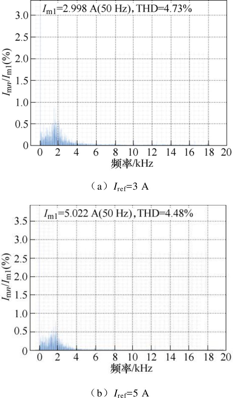
图16 FS-MPCC-Ⅱ在实验2下的输出电流的FFT分析
Fig.16 FFT of output current in Experimental 2 of FS-MPCC-Ⅱ
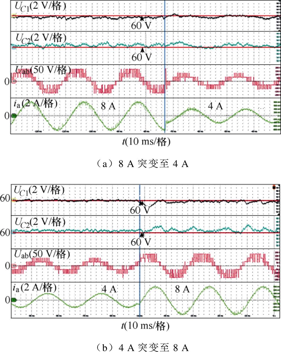
图17 FS-MPCC-Ⅱ在实验3下的直流电容电压UC1、UC2、线电压Uab和电流ia的动态实验结果
Fig.17 Dynamic experimental results of DC-link capacitors voltage UC1, UC2, line voltage Uab and current ia in Experimental 3 of FS-MPCC-Ⅱ
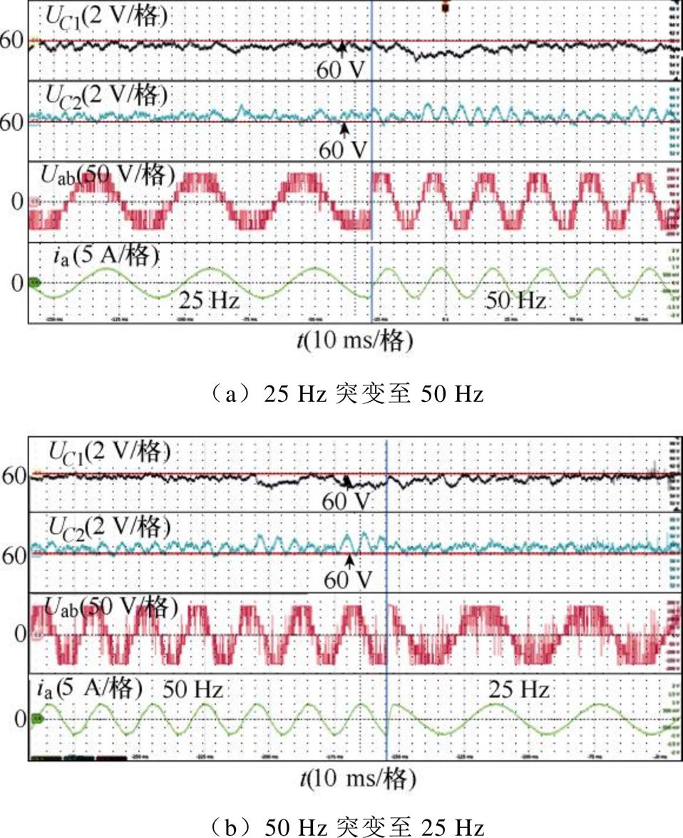
图18 FS-MPCC-Ⅱ在实验4下的直流电容电压UC1、UC2、线电压Uab和电流ia的动态实验结果
Fig.18 Dynamic experimental results of DC-link capacitors voltage UC1, UC2, line voltage Uab and current ia in Experimental 4 of FS-MPCC-Ⅱ
对FS-MPCC-Ⅱ的参数鲁棒性进行验证,如图19所示。设置参考电流幅值和频率分别为6 A和50 Hz。图19a中,三个直流电容值分别设为C1= 750 mF((1-10%)实际值)、C2=840 mF(实际值)和C3=930 mF((1+10%)实际值)。图19b中,电阻R和电感L突变为其实际值的130%。由图19可以看出,无论是直流电容参数突变还是负载参数突变,直流电容电压在突变前后均能平衡在60 V左右,且NPV波动小于2 V,表明FS-MPCC-Ⅱ可有效地平衡电容电压。电流THD分别约为4.88%和5.47%,输出电流质量与实验1基本一致。因此,FS-MPCC-Ⅱ在模型参数的扰动下依然具有较强的鲁棒性。
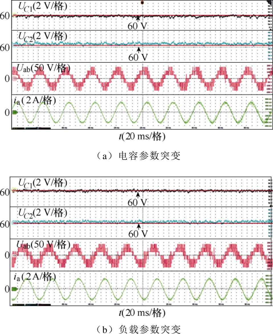
图19 FS-MPCC-Ⅱ参数敏感性实验结果
Fig.19 Parameter sensitivity experimental results of FS-MPCC-Ⅱ
本文针对阻感负载下的4L-ANPC逆变器,提出了一种改进的FS-MPCC算法。该方法避免了复杂的调制,减少了寻优次数。仿真和实验验证了所提控制算法的有效性。结果表明,相比传统FS- MPCC,所提方法不仅具有电流谐波小、直流电容电压均衡以及电流跟踪性能良好的优点,还能较大程度地减少系统计算负担。
参考文献
[1] Rodriguez J, Bernet S, Wu Bin, et al. Multilevel voltage-source-converter topologies for industrial medium-voltage drives[J]. IEEE Transactions on Industrial Electronics, 2007, 54(6): 2930-2945.
[2] 王金平, 刘斌, 董浩, 等. 中点钳位型三电平逆变器基于调制波分解的调制策略[J]. 电工技术学报, 2023, 38(12): 3221-3233.
Wang Jinping, Liu Bin, Dong Hao, et al. A modu- lation strategy based on modulation wave decom- position for neutral point clamped three-level inverter[J]. Transactions of China Electrotechnical Society, 2023, 38(12): 3221-3233.
[3] 徐畅, 宫金武, 张国琴, 等. 中点钳位型三电平逆变器并联系统的零序环流抑制策略[J]. 电工技术学报, 2023, 38(增刊1): 124-135.
Xu Chang, Gong Jinwu, Zhang Guoqin, et al. Zero- sequence circulating current suppression strategy of neutral-point-clamped three-level inverter parallel system[J]. Transactions of China Electrotechnical Society, 2023, 38(S1): 124-135.
[4] 宋琳, 聂子玲, 叶伟伟, 等. 基于前馈解耦控制的有源中点钳位五电平模型预测控制[J]. 电工技术学报, 2023, 38(7): 1910-1920.
Song Lin, Nie Ziling, Ye Weiwei, et al. Research on model predictive control of ANPC-5L permanent magnet synchronous motor based on feedforward decoupling[J]. Transactions of China Electrotechnical Society, 2023, 38(7): 1910-1920.
[5] 辛业春, 王延旭, 李国庆, 等. T型三电平并网逆变器有限集模型预测控制快速寻优方法[J]. 电工技术学报, 2021, 36(8): 1681-1692.
Xin Yechun, Wang Yanxu, Li Guoqing, et al. Finite control set model predictive control method with fast optimization based on T-type three-level grid- connected inverter[J]. Transactions of China Elec- trotechnical Society, 2021, 36(8): 1681-1692.
[6] 严庆增, 张鑫诚. 四电平p 型逆变器无电流传感器均压调制策略[J]. 中国电机工程学报, 2022, 42(增刊1): 279-286.
Yan Qingzeng, Zhang Xincheng. A DC-link capacitor-voltage balancing strategy without current sensors for four-level p-type inverters[J]. Proceedings of the CSEE, 2022, 42(S1): 279-286.
[7] 袁庆庆, 燕磊, 杨丰年, 等. 基于矩形区域分类的NPC型H桥级联五电平逆变器简化模型预测电压控制[J]. 中国电机工程学报, 2023, 43(12): 4758- 4768.
Yuan Qingqing, Yan Lei, Yang Fengnian, et al. A simplified model predictive voltage control for the NPC H-bridge cascaded five-level inverters based on the rectangular region classification[J]. Proceedings of the CSEE, 2023, 43(12): 4758-4768.
[8] 申永鹏, 王帅兵, 梁伟华, 等. T型三电平逆变器合成脉冲宽度调制相电流重构策略[J]. 电工技术学报, 2022, 37(20): 5302-5312.
Shen Yongpeng, Wang Shuaibing, Liang Weihua, et al. T-type three-level inverter composite pulse width modulation phase current reconstruction strategy[J]. Transactions of China Electrotechnical Society, 2022, 37(20): 5302-5312.
[9] Jiao Yang, Lu Sizhao, Lee F C. Switching per- formance optimization of a high power high frequency three-level active neutral point clamped phase leg[J]. IEEE Transactions on Power Electronics, 2014, 29(7): 3255-3266.
[10] Geyer T, Mastellone S. Model predictive direct torque control of a five-level ANPC converter drive system[J]. IEEE Transactions on Industry Appli- cations, 2012, 48(5): 1565-1575.
[11] Jiao Yang, Lee F C. New modulation scheme for three-level active neutral-point-clamped converter with loss and stress reduction[J]. IEEE Transactions on Industrial Electronics, 2015, 62(9): 5468-5479.
[12] Hu Cungang, Yu Xinghuo, Holmes D G, et al. An improved virtual space vector modulation scheme for three-level active neutral-point-clamped inverter[J]. IEEE Transactions on Power Electronics, 2017, 32(10): 7419-7434.
[13] Guan Qingxin, Li Chushan, Zhang Yu, et al. An extremely high efficient three-level active neutral- point-clamped converter comprising SiC and Si hybrid power stages[J]. IEEE Transactions on Power Electronics, 2018, 33(10): 8341-8352.
[14] Xiao Dan, Akter M P, Alam K, et al. Cascaded predictive flux control for a 3-L active NPC fed IM drives without weighting factor[J]. IEEE Transactions on Energy Conversion, 2021, 36(3): 1797-1807.
[15] Wang Kui, Zheng Zedong, Li Yongdong, et al. Neutral-point potential balancing of a five-level active neutral-point-clamped inverter[J]. IEEE Transactions on Industrial Electronics, 2013, 60(5): 1907-1918.
[16] Liu Zhan, Wang Yu, Tan Guojun, et al. A novel SVPWM algorithm for five-level active neutral- point-clamped converter[J]. IEEE Transactions on Power Electronics, 2016, 31(5): 3859-3866.
[17] Oikonomou N, Gutscher C, Karamanakos P, et al. Model predictive pulse pattern control for the five-level active neutral-point-clamped inverter[J]. IEEE Transactions on Industry Applications, 2013, 49(6): 2583-2592.
[18] Dao N D, Lee D C. Operation and control scheme of a five-level hybrid inverter for medium-voltage motor drives[J]. IEEE Transactions on Power Electronics, 2018, 33(12): 10178-10187.
[19] Barbosa P, Steimer P, Steinke J, et al. Active- neutral-point-clamped (ANPC) multilevel converter technology[C]//2005 European Conference on Power Electronics and Applications, Dresden, Germany, DOI: 10.1109/EPE.2005.219713.
[20] Xiang Chaoqun, Du Jingrun, Li Jiayi, et al. Model predictive current control of four-level active neutral point clamped inverter with balanced capacitor voltage[C]//2022 IEEE International Power Elec- tronics and Application Conference and Exposition (PEAC), Guangzhou, Guangdong, China, 2022: 429-434.
[21] Pribadi J, Lee D C. Reconfiguration of four-level active neutral-point-clamped inverters for fault- tolerant operation[C]//2021 IEEE 12th Energy Conversion Congress & Exposition-Asia (ECCE- Asia), Singapore, 2021: 1437-1442.
[22] Pribadi J, Lee D C. Open-switch fault diagnosis in four-level active neutral-point-clamped inverters[C]// 2021 IEEE Energy Conversion Congress and Exposition (ECCE), Vancouver, BC, Canada, 2021: 2576-2581.
[23] 向超群, 范子寅, 王成强, 等. 有源钳位四电平能馈变流器预测电流控制[J]. 铁道科学与工程学报, 2023, 20(1): 333-346.
Xiang Chaoqun, Fan Ziyin, Wang Chengqiang, et al. Predictive current control of four-level active- clamped energy feedback converter[J]. Journal of Railway Science and Engineering, 2023, 20(1): 333-346.
[24] Pribadi J, Park B, Lee D C. Operation of four-level ANPC inverter based on space-vector modulation for common-mode voltage reduction[C]//2019 Inter- national Symposium on Electrical and Electronics Engineering (ISEE), Ho Chi Minh City, Vietnam, 2019: 281-285.
[25] Wang Bingsen. Four-level neutral point clamped converter with reduced switch count[C]//2008 IEEE Power Electronics Specialists Conference, Rhodes, Greece, 2008: 2626-2632.
[26] Jin Bosen, Yuan Xibo. Topology, efficiency analysis, and control of a four-level p-type converter[J]. IEEE Journal of Emerging and Selected Topics in Power Electronics, 2019, 7(2): 1044-1059.
[27] Wang Jun, Yuan Xibo, Jin Bosen. Carrier-based closed-loop DC-link voltage balancing algorithm for four level NPC converters based on redundant level modulation[J]. IEEE Transactions on Industrial Electronics, 2021, 68(12): 11707-11718.
[28] Wang Kui, Zheng Zedong, Li Yongdong. Topology and control of a four-level ANPC inverter[J]. IEEE Transactions on Power Electronics, 2020, 35(3): 2342-2352.
[29] Wang Kui, Zheng Zedong, Li Yongdong. A novel carrier-overlapped PWM method for four-level neutral-point clamped converters[J]. IEEE Transa- ctions on Power Electronics, 2019, 34(1): 7-12.
[30] Rodriguez J, Kazmierkowski M P, Espinoza J R, et al. State of the art of finite control set model predictive control in power electronics[J]. IEEE Transactions on Industrial Informatics, 2013, 9(2): 1003-1016.
[31] 汪逸哲, 黄晟, 廖武, 等. 基于新型虚拟矢量调制方法的IPMSM模型预测电流控制方法[J/OL]. 电工技术学报, 2023: 1-12 [2023-10-30]. https://doi.org/10. 19595/j.cnki.1000-6753.tces.230105.
Wang Yizhe, Huang Sheng, Liao Wu, et al. IPMSM model predictive current control method based on a novel virtual vector modulation method[J]. Transa- ction of China Electrotechnical Society, 2023: 1-12 [2023-10-30]. https://doi.org/10.19595/j.cnki.1000- 6753.tces.230105.
[32] 周汉斌, 杨建, 黄连生, 等. 基于有限状态机的三电平逆变器双矢量模型预测控制策略[J]. 电力系统自动化, 2023, 47(11): 155-164.
Zhou Hanbin, Yang Jian, Huang Liansheng, et al. Double-vector model predictive control strategy of three-level inverter based on finite state machine[J]. Automation of Electric Power Systems, 2023, 47(11): 155-164.
[33] Yang Yong, Chen Rong, Fan Mingdi, et al. Improved model predictive current control for three-phase three-level converters with neutral-point voltage ripple and common mode voltage reduction[J]. IEEE Transactions on Energy Conversion, 2021, 36(4): 3053-3062.
An Improved Model Predictive Control of Four-Level Active Neutral Point Clamped Inverter with Balanced Capacitor Voltage
Abstract Multi-level inverters can generate high-quality stepped AC voltage with advantages such as low harmonic content, switch state redundancy, and small common mode voltage, which is suitable for various power applications. Compared to cascaded H-bridge multi-level inverters, the active neutral point clamped (ANPC) inverter uses few power semiconductors without multiple independent DC sources and is cost-effective for low to medium-voltage applications. Furthermore, compared to diode-based passive, neutral point clamped (NPC) inverters, the ANPC inverter can better distribute power losses among power semiconductors, resulting in higher reliability.
To effectively control a four-level ANPC (4L-ANPC) inverter and avoid using complex modulation strategies, this paper proposes an improved finite set model predictive current control (FS-MPCC) algorithm that adopts a two-step voltage vector selection mechanism to achieve excellent control performance and ensure capacitor voltage balance. Firstly, the improved FS-MPCC evaluates the six large voltage vectors (LVVs) at the outer layer of the four-level voltage vector hexagon. The LVV that minimizes the cost function containing only current errors is selected as the optimal LVV. The LVV does not affect the neutral point (NP) capacitor voltage and cannot suppress neutral point voltage (NPV) fluctuations. In addition, the spatial position of the optimal LVV may not be closest to the reference voltage vector. Directly applying the optimal LVV can cause increased harmonic currents and reduced control system stability. Therefore, in the second stage, the optimal LVV obtained in the first stage is used as the central voltage vector, and all voltage vectors within a 60° range are optimized. The second-stage voltage vectors (13 voltage vectors) include medium voltage vectors (MVVs) and small voltage vectors (SVVs) that can affect the neutral point potential. Each candidate voltage vector is substituted into a cost function with current and capacitor voltage errors for rolling optimization. The final target voltage vector is obtained to suppress current errors and NPV fluctuations. In total, 19 optimizations are performed between the two stages, reducing the iterative calculation amount by 45 compared to traditional FS-MPCC strategies.
Simulation is conducted in Matlab/Simulink, and experimental validation is carried out on a dSPACE-based hardware platform. The results demonstrate that the proposed method maintains capacitor voltage balance while keeping NPV values within allowable limits under different modulation indexes and fundamental frequencies. Compared to traditional methods, the proposed method can quickly respond without decreasing steady-state and dynamic control performance under sudden changes in reference current, fundamental frequency, or system parameters. In addition, dSPACE configuration file tests show that the proposed method reduces system execution time and computational burden while maintaining high computational efficiency.
Keywords:Four-level, active neutral point clamped inverter, finite set model predictive current control, capacitor voltage balance, cost function
中图分类号:TM464
DOI: 10.19595/j.cnki.1000-6753.tces.231214
国家自然科学基金资助项目(52002409)。
收稿日期 2023-07-27
改稿日期 2023-09-25
向超群 男,1988年生,博士,副教授,研究方向为电力电子与电力传动。
E-mail: xcq061017@163.com
Zhang Xinan 男,教授,博士生导师,研究方向为电力电子与电力传动。
E-mail: xinan.zhang@uwa.edu.au(通信作者)
(编辑 陈 诚)