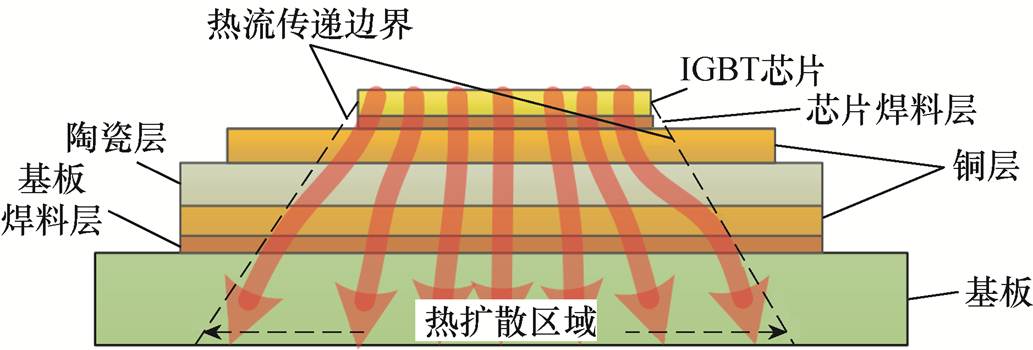
图1 IGBT模块热流路径
Fig.1 The thermal path of the IGBT module
摘要 功率器件因结温波动产生的热-机械应力是其疲劳失效的主要原因,开展结温控制是提升器件可靠性、实现功率变换系统安全运行的重要保障。该文提出一种基于有限时间有界理论的功率器件结温主动控制策略,实现器件结温波动较为精确的控制,降低功率器件在运行过程中的结温波动幅值,减小因结温波动产生的热应力对器件材料的冲击,延缓器件的疲劳老化程度。首先,基于Foster热网络模型建立功率器件结温波动的状态-空间模型,基于有限元分析方法完成模型参数的辨识,实现器件结温状态的实时估计;其次,基于有限时间有界理论完成结温管理反馈控制器的设计,考虑不同工况下器件结温需求,以器件开关频率的调整为例完成器件结温波动的管理,降低结温波动对器件的热冲击作用;最后,仿真和实验结果表明,状态-空间模型估算器件结温的误差约为2%,结温控制结果与设定值差距约1.7%,说明了该文方法在结温估算和管理方面的精度较高。
关键词:功率器件 结温控制 可靠性 热管理
绝缘栅双极型晶体管(Insulated Gate Bipolar Transistor, IGBT)作为功率变换系统的核心部件,已广泛应用于电动汽车、飞机、可再生能源发电系统和高速铁路等领域[1-4]。由于多变的工作环境和复杂的工况,IGBT模块在运行中会产生较大的结温波动,导致器件材料之间产生热-机械应力,应力的持续作用造成器件材料的疲劳老化,最终引发功率变换系统的可靠性问题。研究表明,超过30%的功率变换系统故障是由功率器件失效引起的,而超过60%的功率器件失效是由结温波动引起的[5-7]。因此,从可靠性的角度来看,对功率器件开展结温控制已经成为提升功率变换系统可靠性的一个重要方向[8-11]。
近年来,许多研究机构针对功率器件热疲劳失效开展了结温控制研究,现有的方法通过冷却系统的调节或芯片功耗的配置实现结温的主动控制,此类方法不需要对功率变换系统的结构进行重新设计,具有较好的经济性和适用性[12-15]。目前结温控制方法分为动态冷却法和电参数法两种。动态冷却法通过功率器件冷却系统的主动调节完成结温的控制,文献[16]提出的动态冷却控制策略通过风扇转速或水冷却系统流速的自适应调整使散热功耗与芯片功耗相匹配,从而降低器件运行过程中的结温波动;电参数法则通过调整芯片功耗相关参数来实现芯片结温的主动控制。电参数法通常分为三个层次:调制级、变换器级和系统级。在调制级,一般利用门驱动和调制模式的改变完成芯片功耗的调整;在变换器级,则是通过改变器件可控变量(直流电压、电流和开关频率等)的方法降低器件结温幅值[17];在系统级,多个功率变换器的灵活组合可实现器件功耗的平衡[18]。动态冷却法和电参数法均可降低器件的结温波动幅值,减少热-机械应力对器件材料的冲击作用,但其更关注如何使器件在全负荷运行状态下结温不超过安全阈值,而不能根据应用场合或需求值对结温波动进行较为精确的控制,难以实现器件的精细化热管理,因而不利于高铁、航天领域等高可靠性应用场合。
针对上述问题,本文提出了一种基于有限时间有界理论的结温控制策略,通过反馈控制器主动配置芯片功耗或调节散热系统,将器件结温波动限定在期望的范围内,实现器件结温的精细化管理,降低功率器件因疲劳老化突发失效的风险,从而提升功率变换系统的整体可靠性。首先,基于Foster热网络模型建立功率器件结温波动的状态-空间模型,采用有限元分析法(Finite Element Analysis, FEA)完成模型参数的辨识;其次,基于有限时间有界理论完成结温反馈控制器的设计,以器件开关频率的调整为例实现器件结温波动的控制;最后,通过仿真分析和实验结果对本文提出方法的有效性进行验证。
功率器件结温波动是由芯片功耗决定的,如何准确描述器件结温与芯片功耗的关系是实现结温精确控制的重要条件。状态-空间模型作为动态时域模型,以隐含时间为自变量,其状态方程模型可反映系统在输入变量作用下某时刻所转移到的状态;而其输出方程将系统在某时刻输出和系统的状态及输入变量联系起来。因此,状态-空间模型既可获取器件的结温状态,又可描述器件结温与芯片损耗的关系。本节基于Foster热网络模型构建功率器件结温的状态-空间模型,并采用FEA完成模型参数的辨识。
芯片功耗是器件内部热量的主要来源。芯片处产生的热量自上而下穿过各层材料后到达散热板底部,其热流路径如图1所示。

图1 IGBT模块热流路径
Fig.1 The thermal path of the IGBT module
热流路径代表着器件内部的热特性,可用芯片到散热板底部的瞬态热阻抗ZJA(t)进行表征,即
 (1)
(1)
式中,TJ(t)为器件芯片结温;TA(t)为散热板底部结温,TA(t)可通过散热板底部布设的结温传感器测量得到;P为芯片功耗。
为便于模型推导,令 ,式(1)可写为
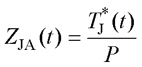 (2)
(2)
式中, 为芯片与散热板底部结温差。
Foster热等效电路模型如图2所示,R和C分别为热阻和热容。图2的Foster模型可通过一系列指数参数表示,将ZJA(t)与Foster模型融合得
 (3)
(3)

图2 Foster热等效电路模型
Fig.2 Foster-type thermal equivalent circuit model
对式(3)进行拉普拉斯变换后得到ZJA(t)传递函数的频域展开式为
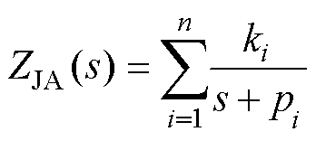 (4)
(4)
式中, 和
和 分别为传递函数的零点和极点;s表示复变量。
通过代数变换,可得传递函数的零点和极点与RC参数关系分别为
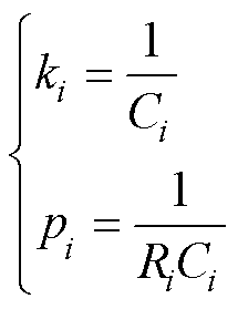 (5)
(5)
需要说明的是,Foster网络为器件热传递系统的热等效模型,RC参数与器件热路径的特性不具备对应关系,整体热特性是相同的。式(4)变为状态-空间模型为
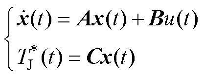 (6)
(6)
式中,x(t)为热传递路径上的热量;u(t)代表系统的输入,即功率器件损耗Ptot;输出方程输出的则是 ;通过传递函数零点、极点和RC参数之间的关系,得状态-空间模型的参数矩阵分别为
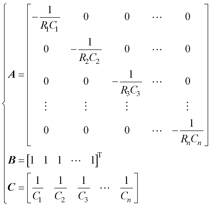 (7)
(7)
式中,A为n×n所系统矩阵;B为1×n所输入矩阵;C为1×n所输出矩阵。
式(7)的矩阵参数是由Foster网络的RC参数组成的,通过RC参数的识别可完成状态-空间热模型参数的辨识。Foster网络作为等效电路模型,参数可由瞬态热阻抗曲线ZJA(t)得到,ZJA(t)曲线可通过FEA获取。分析功率器件的机械结构和材料特性,采用PRO/E软件建立三维模型并导入到Ansys软件中进行瞬态热分析。瞬态热分析过程设置如下:①散热板采用强制对流冷却;②IGBT模块为半桥逆变工作模式,芯片功耗由通态损耗和开关损耗组成;③在Ansys软件中进行瞬态热分析,运行时间为10 s,采样间隔为0.001 s。
功率器件功耗Ptot包括通态损耗Pcond和开关损耗Psw,即
 (8)
(8)
器件通态损耗为
 (9)
(9)
式中,VCE-ON为器件导通压降;IC为负载电流;D为占空比。
器件开关损耗为
 (10)
(10)
式中,Eon为器件导通能量;Eoff为器件关断能量;f为器件开关频率。器件导通能量和关断能量受直流电压和芯片结温的影响,Eon和Eoff可分别表示为
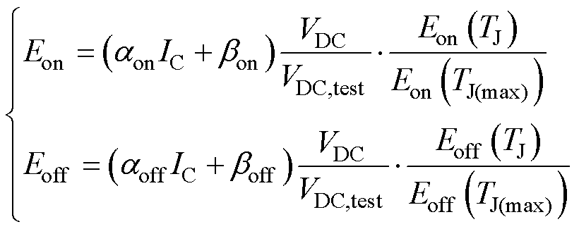 (11)
(11)
式中,aon、bon、aoff、boff为器件导通和关断能量参数;Eon(TJ(max))、Eoff(TJ(max))为芯片额定最高结温时器件导通和关断能量,aon、bon、aoff、boff、Eon(TJ(max))、Eoff(TJ(max))可从厂商数据手册中查到;VDC为器件运行时负荷电压;VDC,data为厂商测试时的电压;Eon(TJ)、Eoff(TJ)为芯片运行结温时导通和关断能量,通过电压和能量比例可消除不同工况对器件能量的影响,Eon(TJ)、Eoff(TJ)根据芯片结温TJ查询厂商数据手册得到,初始的器件结温TJ为室温。将功率损耗施加在IGBT芯片上,得到IGBT瞬态热分析结果如图3所示。
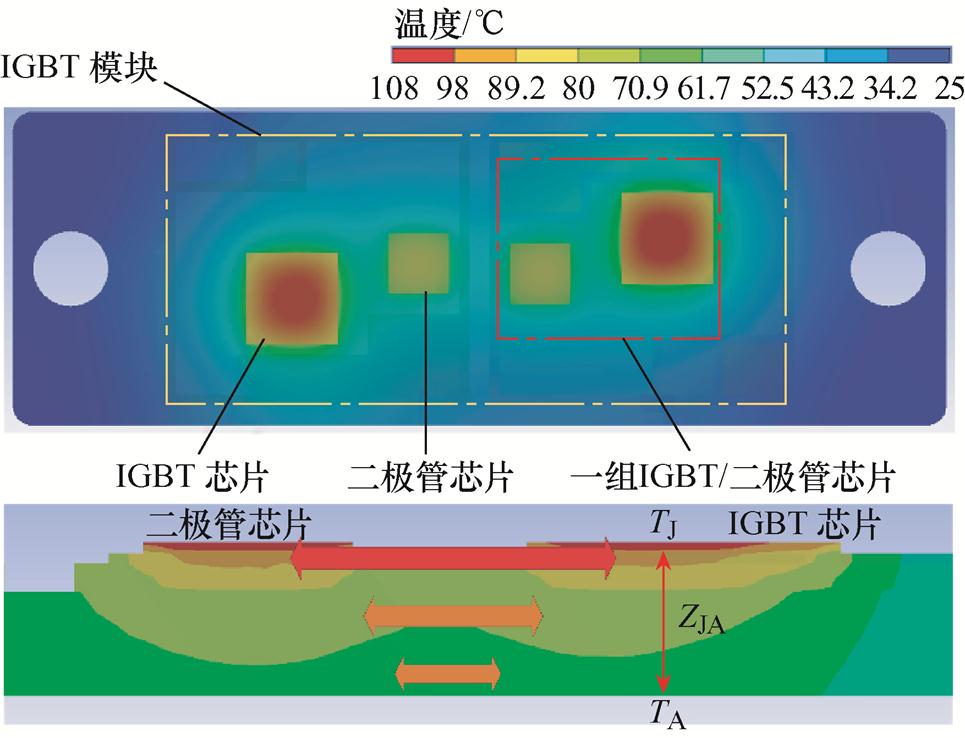
图3 IGBT模块瞬态热分析结果
Fig.3 The results of thermal analysis for the IGBT module
将仿真分析结果代入式(1)得到IGBT的瞬态热阻抗曲线ZJA(t),如图4所示。四阶Foster热网络可准确描述器件的瞬态热阻抗特性。采用式(3)通过最小二乘法对热阻抗曲线进行拟合,得到RC参数见表1。
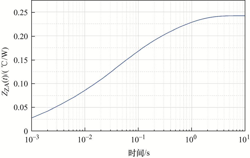
图4 IGBT模块瞬态热阻曲线
Fig.4 The transient thermal impedance of IGBT module
表1 识别的状态-空间模型参数
Tab.1 The identified state-space model parameters

i1234 Ri/(K/W)0.180.0640.0220.004 Ci/(J/K)0.1820.750.361.25
上述构建的功率器件状态-空间热模型可准确描述芯片功耗和器件结温的关系,为实现器件结温的准确控制提供了条件。
现有结温控制方法不能根据应用场合或需求对结温波动进行较为精确的控制,难以实现器件的精细化热管理。本文设计了一种基于有限时间有界理论的状态反馈控制器,通过反馈控制器精确配置芯片功耗或调节散热系统,将器件结温波动限定在需求的范围内。
一个系统在一段运行时间内始终不超过某个边界,那么这个系统是有限时间有界的[19-22]。对于器件结温波动而言,依据有限时间有界概念,可以将其限定在某个特定的范围内。
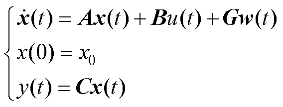
式(6)的状态-空间模型为器件的结温波动系统,考虑外部扰动因素,式(6)可转化为
 (12)
(12)
式中, w(t)为恒定扰动,满足
 。
。
针对式(12)设计反馈控制器为
 (13)
(13)
式(12)和式(13)组成结温波动的闭环反馈系统,若系统符合式(14)条件,则被认为是有限时间有界。
 (14)
(14)
式中,R为正定矩阵; ,
, ;
; 为设定的结温波动边界。
根据文献[22-25]对式(12)和式(14)变换后可得
 (15)
(15)
对于特定的器件结温波动系统而言, 的数值是固定的,边界
 则根据现场应用情况或需求值设定,因而上述系统输出是范数有界的。若存在正定矩阵
 、
、 和正标量a 满足不等式式(16)、式(17),则可使器件的结温波动系统满足有限时间有界。
 (16)
(16)
 (17)
(17)
式中,Q1、Q2、L、R为正定矩阵; 分别为正定矩阵
 的最小和最大特征值;
 ;控制矩阵K满足
 。
。
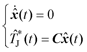
基于有限时间有界理论,设计反馈控制器以完成器件结温波动的精确控制。考虑式(6)的功率器件结温波动系统及功率器件结温波动的目标系统为
 (18)
(18)
式中, 为目标系统状态;
 为目标系统的输出。定义两个系统之间的状态误差
 以及系统控制器
 。在特定时间内tÎ[0,T],两个系统的差距可描述为
 (19)
(19)
考虑 以及
以及 ,式(19)可转化为
 (20)
(20)
令 ,式(20)可表示为
 (21)
(21)
式中, 为误差系统扰动。考虑有限时间有界系统满足的不等式
 及
及 ,得到
,得到
 (22)
(22)
根据 对式(22)进行变换得
 (23)
(23)
由式(22)和式(23)得到
 (24)
(24)
式中, 为结温波动范围。通过式(24)可知,功率器件结温波动可控制在目标状态
 附近,并且以
 为边界摆动。
功率器件结温波动控制方案如图5所示,通过传感器系统采集功率器件的开关频率fsw、负载电流IC、直流电压VDC、通态电压VCE-ON、导通能量Eon和关断能量Eoff等多种电气参数,并基于采集信息计算器件的芯片功耗;根据2.2节提出的方法设计反馈控制矩阵K,构造系统反馈控制器
 ,通过控制器反馈的信息对芯片功耗进行配置或对散热系统进行调整,完成器件结温波动的控制。
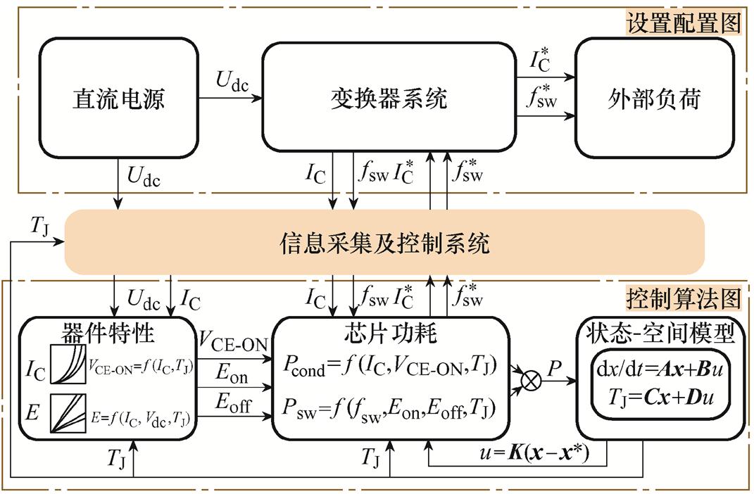
图5 基于模型的功率器件结温控制示意图
Fig.5 A model-based active temperature control scheme
为深入分析器件结温波动控制性能,在相同条件下对器件开展有限元分析,功率器件运行条件设置如下:①散热方式为水冷,冷却面保持25℃不变;②功率器件为半桥逆变工作模式;③开关频率fsw基本值为10 kHz,可在6~15 kHz之间变化;④调制频率f0=10 Hz;⑤在Ansys瞬态热分析模式下运行10 s;⑥以器件开关频率调整为例对芯片功耗进行配置。芯片功耗的影响因素包括门级驱动器、门级电阻、调制策略、直流电压、开关频率、散热转速等[23],在实际应用中,可在不影响变换器输出性能的前提下,通过上述某种或某几种因素的调整实现芯片功耗的主动配置。
根据器件运行条件计算芯片功耗,将芯片功耗输入状态-空间模型和有限元分析软件中,得到结温结果如图6所示。图6中,状态-空间模型估计的结温结果与有限元分析结果基本一致,两种结温波形的相关系数大于0.95,结温最大差别为1.2℃,是由状态-空间模型参数辨识过程中的误差造成的。上述结果表明状态-空间模型可准确估算器件结温。
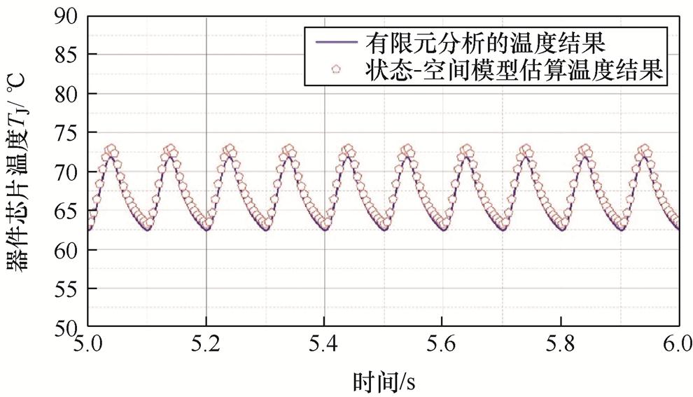
图6 状态-空间模型与有限元分析输出结果
Fig.6 TJ estimate by the state-space model compared to FEA results
图6中,当器件结温波动达到10℃时,会导致器件产生较为严重的热疲劳损伤,造成器件老化进程加速,在现场条件下应采取有效措施降低器件结温波动幅值,减小结温冲击对器件造成的热损伤。功率器件结温波动数值是根据现场情况或需求值进行设定的,根据图6设定器件运行的期望结温和波动值,分别为60℃和3℃。通过式(18)和式(24)可得
 (25)
(25)
将 和
和 代入式(25)计算
 和
和 ,并将
,并将 和
和 的结果代入式(16)和式(17)计算反馈控制矩阵K,有

通过反馈控制矩阵设计控制器u(t)=
 ,控制器的输出为芯片功耗调整量,以开关频率调整为例分析芯片功耗的配置效果。在Matlab中搭建器件结温仿真环境,图7为施加控制前后的器件结温结果,与未施加控制的结温结果相比,经控制后的器件结温和波动均有明显减小,降低了结温冲击对器件造成的热损伤。此外,经控制后的器件平均结温约等于设定值(即60℃),且结温波动范围未超过设定边界(3℃),表明所设计的控制器可实现对器件结温波动的精确控制。
仿真结果表明,设计的状态-空间模型可较为准确地估算器件结温,反馈控制器可实现对器件结温波动的精确控制,对于提升器件复杂工况下可靠性能具有重要作用。
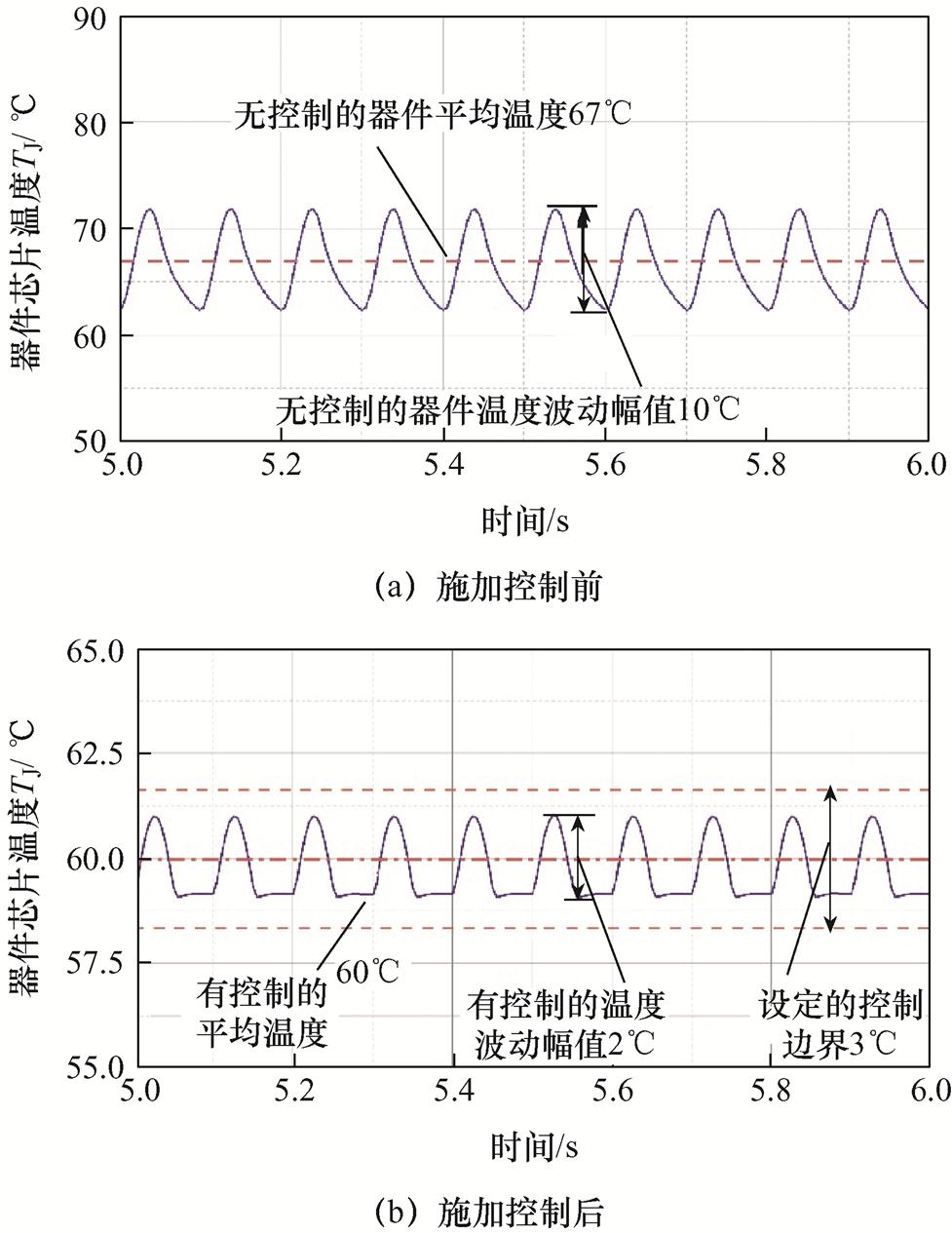
图7 施加控制前后的器件结温结果对比
Fig.7 Simulation results of temperature estimation with and without the controller
实验平台如图8所示,包括上位机、dSPACE控制器、功率器件(塞米控SKM75GB 07E3,额定电压和电流分别为600 V和75 A)构成的驱动电路、半桥逆变器、电子负载、直流电源(固纬PSW-1080,最大输出电压和电流分别可达800 V和108 A)和铝制散热器等。实验运行条件设置如下:①功率器件采用铝制散热板进行自然对流散热;②dSPACE系统作为控制器向驱动器发射控制信号,并采集器件的通态电压和电流等信息;③功率器件负荷电流为50 A;④开关频率fsw的基本值为10 kHz,变化范围为6~15 kHz;⑤实验运行时间大约为300 s。
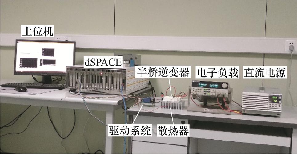
图8 实验平台
Fig.8 The experimental setup
为深入分析状态-空间模型估算器件结温的准确性,同时测量器件的通态电压VCE-ON获取器件结温,将两者结温结果进行对比。VCE-ON为功率器件的热敏电参数,对器件结温的变化非常灵敏,但也受集电极电流的影响,通过离线实验建立不同集电极电流IC下VCE-ON与器件结温的关系如图9所示。离线实验条件为:①在门极施加直流电压使器件导通;②通过直流电源施加集电极电流使器件结温不断上升;③采用录波仪和红外摄像头分别测量不同集电极电流下的VCE-ON和器件结温,建立VCE-ON-IC-TJ三者的关系曲线。在实验分析中,通过采集的VCE-ON和IC可获取器件结温。
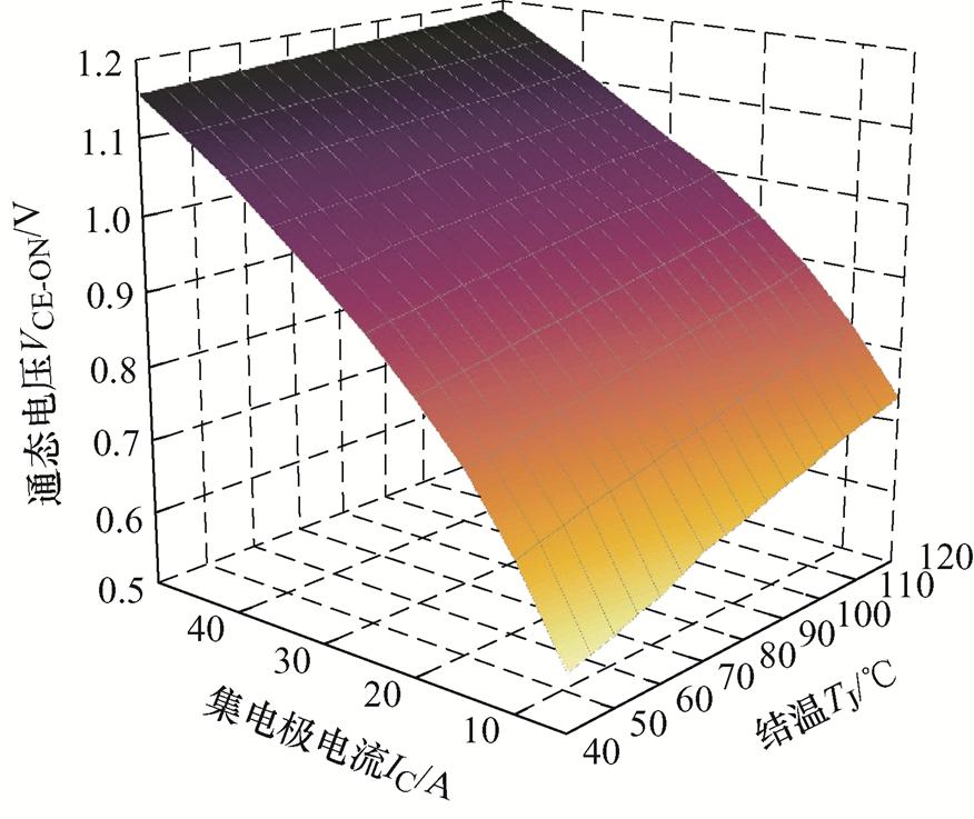
图9 VCE-ON与器件结温的关系
Fig.9 The relationship between VCE-ON and the junction temperature
通过dSPACE系统采集功率器件的电气参数并计算芯片功耗,将芯片功耗输入状态-空间模型中得到器件结温结果;同时根据采集的VCE-ON计算器件结温,进行结温结果对比如图10所示。图10中,状态-空间模型估算的结温结果可准确跟踪VCE-ON的测量结果,两者最大误差约为2.8%。两种信号的最大差值位于结温曲线的峰值处,约为2.2℃,差值是由状态-空间模型建模过程中的误差和VCE-ON的测量噪声造成的。需要说明的是,仿真部分采用的是水冷系统,而实验部分则是自然对流散热,散热方式的区别造成两者的结温结果略有不同。上述结果表明,状态-空间模型可准确获取器件结温波动信息。
根据2.2节的方法设计反馈控制器对器件结温波动进行管理。图10中的器件结温波动为10℃左右,将导致器件内部产生较大的热-机械应力,造成功率器件的疲劳老化进程加速。功率器件结温波动数值根据图10中结果设定,期望的结温和波动值分别设为60℃和5℃。
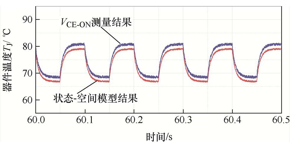
图10 状态-空间模型结温结果与VCE-ON结温结果对比
Fig.10 TJ estimate by the state-space model compared to VCE-ON measurements
利用式(26)计算 和
和 ,将
,将 和
和 数值代入到式(16)和式(17)中,得到反馈控制矩阵
K=[-20.3156 -24.3023 -86.7256 -160.7023]
基于反馈控制矩阵设计控制器u(t)=
 ,控制器输出的是器件需要调整的芯片功耗,以开关频率调整为例分析芯片功耗的配置效果。在相同的实验条件下对控制前后的功率器件进行测试,施加控制前后的器件结温波动结果对比如图11所示。
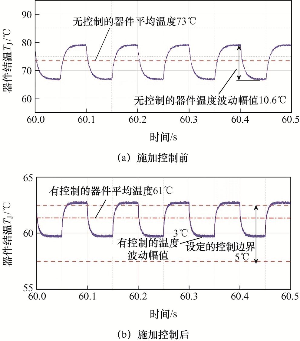
图11 施加控制前后的实验结果对比
Fig.11 Experimental results of the junction temperature with and without the controller
与未施加控制的结温结果相比,经控制后的器件结温和波动均有明显的降低,使结温冲击对器件的热损伤大幅减小。此外,经控制后器件平均结温约等于设定值,且结温波动范围总体位于设定的边界(5℃)。需要说明的是,由于开关频率调整范围的限制,控制后的结温与设定的期望结温略有不同。整体上看,设计的控制器可以实现对器件结温波动较为精确的控制。
针对结温波动引起的功率器件热疲劳损伤,提出了基于有限时间有界理论的结温控制策略,根据Foster热网络建立了功率器件结温波动的状态-空间模型,通过芯片功耗实现器件结温的准确估算,在仿真和实验分析中,状态-空间模型的结温结果与测量的结温结果相差2%左右,造成差别的主要原因是状态-空间模型建模过程中的参数辨识误差和VCE-ON的测量噪声。根据有限时间有界理论设计了器件结温反馈控制器,以开关频率调整为例,通过控制器完成芯片功耗的配置,实现器件结温波动的控制。仿真和实验结果表明,施加控制后器件平均结温约等于设定值,且结温波动范围总体位于设定的边界。总体上看,本文提出的方法可实现器件结温波动较为精确的控制,对减小结温波动对器件材料造成的热冲击、延缓器件的疲劳损伤进程具有重要作用。
附 录
功率器件结温系统为线性定常系统,可写为
 (A1)
(A1)
引理(有限时间有界的充分条件):系统式(A1)对于 是有限时间有界的,
 均为正标量,如果存在正定矩阵
 和
和 及正标量
及正标量 ,并且满足
,并且满足
 (A2)
(A2)
 (A3)
(A3)
其中

证明:假设 和
和 。若想证明,如果条件式(A2)和式(A3)成立,那么对于所有
 ,
, 成立。
成立。
令 。经简单换算可知式(A2)表示为
 (A4)
(A4)
对式(A4)从0~t进行积分,得到
 (A5)
(A5)
令 ,考虑到
,考虑到 ,可以得到
,可以得到

 (A6)
(A6)

 (A7)
(A7)
由式(A6)和式(A7)可得
 (A8)
(A8)
由式(A8)可知,式(A3)意味着,对于所有 ,
, 。那么系统式(A1)对于
 是有限时间有界的。
参考文献
[1] Ji Bing, Pickert V, Cao Wenping, et al. In situ diagnostics and prognostics of wire bonding faults in IGBT modules for electric vehicle drives[J]. IEEE Transactions on Power Electronics, 2013, 28(12): 5568-5577.
[2] Cao Wenping, Mecrow B C, Atkinson G J, et al. Overview of electric motor technologies used for more electric aircraft (MEA)[J]. IEEE Transactions on Industrial Electronics, 2012, 59(9): 3523-3531.
[3] Senturk O S, Helle L, Munk-Nielsen S, et al. Power capability investigation based on electrothermal models of press-pack IGBT three-level NPC and ANPC VSCs for multimegawatt wind turbines[J]. IEEE Transactions on Power Electronics, 2012, 27(7): 3195-3206.
[4] Gong Xun, Ferreira J A. Comparison and reduction of conducted EMI in SiC JFET and Si IGBT-based motor drives[J]. IEEE Transactions on Power Electronics, 2014, 29(4): 1757-1767.
[5] Luo Haoze, Chen Yuxiang, Sun Pengfei, et al. Junction temperature extraction approach with turn-off delay time for high-voltage high-power IGBT modules[J]. IEEE Transactions on Power Electronics, 2016, 31(7): 5122-5132.
[6] 魏云海, 陈民铀, 赖伟, 等. 基于IGBT结温波动平滑控制的主动热管理方法综述[J]. 电工技术学报, 2022, 37(6): 1415-1430.
Wei Yunhai, Chen Minyou, Lai Wei, et al. Review on active thermal control methods based on junction temperature swing smooth control of IGBTs[J]. Transactions of China Electrotechnical Society, 2022, 37(6): 1415-1430.
[7] 范迦羽, 郑飞麟, 王耀华, 等. 计及热阻与发射极电感匹配的并联IGBT芯片稳态结温均衡方法[J]. 电工技术学报, 2022, 37(12): 3028-3037.
Fan Jiayu, Zheng Feilin, Wang Yaohua, et al. Steady temperature equalization method for the parallel IGBTs considering the thermal resistance and the matching emitter parasitic inductance[J]. Transactions of China Electrotechnical Society, 2022, 37(12): 3028-3037.
[8] Wang Huai, Liserre M, Blaabjerg F, et al. Transitioning to physics-of-failure as a reliability driver in power electronics[J]. IEEE Journal of Emerging and Selected Topics in Power Electronics, 2014, 2(1): 97-114.
[9] Choi U M, Blaabjerg F, Lee K B. Study and handling methods of power IGBT module failures in power electronic converter systems[J]. IEEE Transactions on Power Electronics, 2015, 30(5): 2517-2533.
[10] 李辉, 刘人宽, 王晓, 等. 压接型IGBT器件封装退化监测方法综述[J]. 电工技术学报, 2021, 36(12): 2505-2521.
Li Hui, Liu Renkuan, Wang Xiao, et al. Review on package degradation monitoring methods of press-pack IGBT modules[J]. Transactions of China Electrotechnical Society, 2021, 36(12): 2505-2521.
[11] 张军, 张犁, 成瑜. IGBT模块寿命评估研究综述[J]. 电工技术学报, 2021, 36(12): 2560-2575.
Zhang Jun, Zhang Li, Cheng Yu. Review of the lifetime evaluation for the IGBT module[J]. Transactions of China Electrotechnical Society, 2021, 36(12): 2560-2575.
[12] Eleffendi M A, Johnson C M. Application of Kalman filter to estimate junction temperature in IGBT power modules[J]. IEEE Transactions on Power Electronics, 2016, 31(2): 1576-1587.
[13] Xu Zhuxian, Xu Fan, Wang Fei. Junction temperature measurement of IGBTs using short-circuit current as a temperature-sensitive electrical parameter for converter prototype evaluation[J]. IEEE Transactions on Industrial Electronics, 2015, 62(6): 3419-3429.
[14] 杨舒萌, 孙鹏菊, 王凯宏, 等. 恒流驱动下基于VeE_max的IGBT模块解耦老化影响的结温测量方法[J]. 电工技术学报, 2022, 37(12): 3038-3047, 3072.
Yang Shumeng, Sun Pengju, Wang Kaihong, et al. Junction temperature measurement method of IGBT modules based on VeE_max under constant-current source drive which decouples fatigue effect[J]. Transactions of China Electrotechnical Society, 2022, 37(12): 3038-3047, 3072.
[15] 张玉斌, 温英科, 阮琳. 全浸式蒸发冷却IGBT电热耦合模型研究[J]. 电工技术学报, 2022, 37(15): 3845-3856.
Zhang Yubin, Wen Yingke, Ruan Lin. Research on electrothermal coupling model of fully-immersed evaporative cooling IGBT[J]. Transactions of China Electrotechnical Society, 2022, 37(15): 3845-3856.
[16] Wang Xiang, Castellazzi A, Zanchetta P. Observer based temperature control for reduced thermal cycling in power electronic cooling[J]. Applied Thermal Engineering, 2014, 64(1/2): 10-18.
[17] Wei Lixiang, McGuire J, Lukaszewski R A. Analysis of PWM frequency control to improve the lifetime of PWM inverter[J]. IEEE Transactions on Industry Applications, 2011, 47(2): 922-929.
[18] Ma Ke, Liserre M, Blaabjerg F. Reactive power influence on the thermal cycling of multi-MW wind power inverter[J]. IEEE Transactions on Industry Applications, 2013, 49(2): 922-930.
[19] Amato F, Ariola M, Dorato P. Finite-time control of linear systems subject to parametric uncertainties and disturbances[J]. Automatica, 2001, 37(9): 1459-1463.
[20] Amato F, Ariola M. Finite-time control of discrete-time linear systems[J]. IEEE Transactions on Automatic Control, 2005, 50(5): 724-729.
[21] Amato F, Ariola M, Cosentino C. Finite-time stabilization via dynamic output feedback[J]. Automatica, 2006, 42(2): 337-342.
[22] Amato F, Ariola M, Cosentino C. Finite-time control of discrete-time linear systems: analysis and design conditions[J]. Automatica, 2010, 46(5): 919-924.
[23] Andresen M, Ma Ke, Buticchi G, et al. Junction temperature control for more reliable power electro- nics[J]. IEEE Transactions on Power Electronics, 2018, 33(1): 765-776.
Active Control and Optimization Strategy of Junction Temperature for Power Devices
Abstract As the core component of the power conversion system, the insulated gate bipolar transistor (IGBT) has been widely used in electric vehicles, aircraft, renewable energy power generation systems, and high-speed railways. Due to the changeable work environment and complex operating conditions, the IGBT module produces a great junction temperature fluctuation during operation, resulting in thermal-mechanical stress in the device. The continuous action of stress will cause degradation of the device, and eventually cause reliability problems of the power conversion system. Studies have shown that power device failures cause more than 30% of power conversion system failures. Moreover, more than 60% of device failures are attributed to the junction temperature fluctuations. Therefore, from the reliability view, the temperature management of power devices has become a significant way to improve the reliability of power conversion systems. The temperature management methods consist of two categories: the dynamic-cooling method and the electrical-parameter method. The dynamic cooling method realizes the temperature control through the active adjustment of the cooling system, and the electrical-parameter method realizes the active configuration of the junction temperature by controlling the parameters related to the device's power loss. However, the current two methods pay more attention to making the device's junction temperature not exceed the safety threshold under full load, while cannot accurately control the junction temperature fluctuation according to the application situation or the demand value. As a result, it is difficult to realize the fine thermal management of the device, which is unfavorable to the application scenario of high reliability. Therefore, an active control strategy of the power device's junction temperature based on finite time boundness theory is proposed in this paper to achieve more accurate control of junction temperature fluctuation. This aim is to reduce the amplitude of junction temperature fluctuation during the operation. Accordingly, the thermal stress caused by the temperature fluctuations decreases. The reliability of power devices is improved by reducing the thermal damage caused by thermal stress. Firstly, the state-space model of the power devices is established based on the Foster thermal network model to achieve real-time estimation of the junction temperature state of devices, and the model parameters are identified based on the finite element analysis method. Secondly, the feedback controller based on the finite time boundness theory for junction temperature management is designed. Considering the junction temperature requirements under different working conditions, the device's switching frequency is selected as the electrical parameter to manage the junction temperature fluctuation and reduce the thermal effect of temperature fluctuations on the device. The simulation and experimental results show that the estimation error of junction temperature by the state-space model is about 2%, and the difference between the junction temperature control result and the set value is about 1.7%, indicating that the proposed method has high precision in estimation and control of junction temperature.
Keywords:Power device, temperature control, reliability, thermal management
中图分类号:TM46;G521
DOI: 10.19595/j.cnki.1000-6753.tces.231234
国家自然科学基金项目(52307207)、国家自然科学基金区域创新发展联合基金重点支持项目(U22A20226)和江苏省高等学校自然科学研究面上项目(22KJB470007)资助。
收稿日期 2023-04-14
改稿日期 2023-05-14
胡 震 男,1989年生,博士,讲师,研究方向为电力电子设备故障的智能化诊断。
E-mail: huzhen0111@njupt.edu.cn
施 涛 男,1982年生,博士,副教授,研究方向为新能源与储能运行控制技术。
E-mail: shitao@njupt.edu.cn(通信作者)
(编辑 陈 诚)