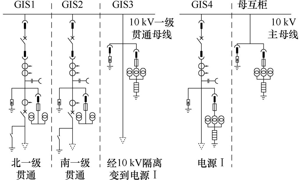
图1 L配电所电气主接线图
Fig.1 The main wiring diagram of L distribution station
摘要 高速铁路10 kV供电系统是含时变激励的非线性非自治系统,以至于该系统中必然存在丰富的复杂非线性现象。该文在考虑系统中磁饱和电感的非线性特性的基础上,构建系统数学模型,并基于谐波平衡法求解系统周期解的近似表达式,推导系统周期时变雅克比矩阵,以Floquet理论识别系统周期解的稳定性,揭示系统出现铁磁谐振时的物理机理,分析系统参数变化对系统产生铁磁谐振的影响,给出ATPDraw环境下的电路仿真结果。研究结果表明:系统铁磁谐振现象产生的机理是由于系统发生了鞍结分岔,且随着饱和相串、并联电容的变化,系统能够保持稳定运行的临界激励幅值Em会随之产生变化。另外,理论计算结果和ATPDraw仿真结果一致,表明采用谐波平衡法和Floquet理论可有效分析高速铁路10 kV供电系统中的铁磁谐振现象。
关键词:铁磁谐振 非线性 谐波平衡 鞍结分岔
铁磁谐振特指具有铁心饱和、磁滞等非线性特性的电感和电容之间出现的振荡现象[1-2]。与线性电路中当激励源频率和电感、电容形成的电路固有频率匹配时产生线性谐振[3]不同,对于含有非线性特性铁磁材料、具有铁磁谐振现象的电路,在特定的激励和电路参数范围,可能存在多种周期稳态解或非周期解,且铁磁谐振系统对初始条件如激励源幅值、线性元件参数以及非线性元件自身特性等非常敏感。这种铁磁谐振现象对于配电操作人员来说较难理解且较“随机”,但又会对配电网造成灾难性破坏[4-8],所以有关铁磁系统谐振产生机理的研究是一项具有重要理论意义和实际工程价值的研究课题。
迄今为止,已有较多论文来描述和讨论铁磁谐振。例如,提出了基于三相平衡关系的矢量图法[9-10]和基于伏安特性曲线的图解法[11-12],但这两种方法主要从系统失稳的宏观角度来定性描述,而不是从电感非线性特性的本质上定量分析。其中矢量图法主要针对三相配电网进行分析,由于电压互感器或轻载变压器铁心饱和后造成三相导纳值不相等,从而引起三相不平衡[13],引起中性点偏移而出现工频过电压现象[14];图解法可比较直观地描述外施电源和平衡点的关系,找到稳定点和跃变现象,但由于系统中非线性因素的存在,这种方法无法量化分析各参数对系统稳定性的影响,更无法进一步阐述系统失稳机理。此外,研究人员还在特定仿真软件如PSCAD、ATP-EMTP等环境下搭建仿真电路来对铁磁谐振现象进行模拟[6-7, 15-16],然而,这种方法只能给出电路对一组特定参数或初始条件的响应,不能给出在参数变化过程中系统的动力学行为,更无法从根本上揭示铁磁谐振现象的产生机理。文献[17-23]从铁磁谐振现象的非线性特性出发,列写系统状态方程,并通过数值计算描绘其时域波形、相图、分岔图或Lyapunov指数谱图来研究系统参数与其局部或全局稳定的相互关系,其研究成果虽能对铁磁谐振现象产生的规律进行数值仿真分析,但是对系统引起谐振现象发生的物理机理无法阐明。文献[24]将链控型非线性电感的磁链采用谐波叠加的形式表达,推导出系统的解析表达式,然后通过根的判别式分析解的存在与否来判断谐振的产生条件。文献[25-26]将非线性电感磁饱和曲线分段线性化表示,然后推导系统的时域解析解,该法的最大不足是线性化分段的精度与解析式的复杂程度正相关,所以要有足够精度,则解析式的求解难度大大增加。
综上所述,以往研究主要从数值仿真的角度粗略地展示了铁磁谐振现象,而未能揭示铁磁谐振现象产生的物理机理,以至于无法从本质上理解铁磁谐振现象。为解决此问题,本文以高速铁路10 kV供电系统为研究对象,在考虑系统中磁饱和电感的非线性特性的基础上,建立简化系统的电路模型,推导系统的数学模型,采用谐波平衡法计算系统的近似周期解,以Floquet理论识别系统周期解的稳定性,并揭示系统产生铁磁谐振时的物理机理,分析系统参数对系统铁磁谐振现象发生的影响,并以ATPDraw电路仿真结果验证理论分析的正确性。
高速铁路10 kV供电系统由大量含有铁磁材料的电感(电力变压器、电磁式电压互感器(Voltage Transformer,VT)、并联电抗器)、断路器并联电容或线路分布电容(主要为输电线路或电力电缆)组成。需要注意的是,铁磁材料一般具有磁饱和非线性特性。由于非线性电感和电容以及激励源的存在,构成了铁磁谐振发生的基础条件。以下是某高速铁路10 kV供电系统L配电所由于铁磁谐振导致设备烧损的典型事故案例,图1为L配电所电气主接线图。

图1 L配电所电气主接线图
Fig.1 The main wiring diagram of L distribution station
1)2022年4月1日19时37分05秒,L配电所某区间一级贯通母线气体绝缘开关(Gas Insulated Switchgear, GIS)2、电源ⅠGIS4失压跳闸,一路系统短时无电。经现场检查发现,GIS4柜线路B相电压互感器绝缘击穿炸裂,三相电压互感器保险均熔断,如图2所示。
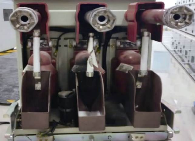
图2 L配电所1GIS4柜线路电压互感器损坏情况
Fig.2 The damage of the VT in 1GIS4 cabinet of the L power distribution station
故障过程大致如下:
(1)19时36分04秒440毫秒,L配电所电源Ⅰ线路电压互感器及母互柜母线电压互感器电压异常:电源Ⅰ线路侧电压互感器A相5.7 kV、B相5.9 kV、C相6.64 kV;母互柜电压互感器:A相5.7 kV、B相5.7 kV、C相6.6 kV,C相电压略偏高,持续时间2秒374毫秒。
(2)19时36分04秒460毫秒出现大电流,电流A相19.2 A、B相19.1 A,C相44.9 A(正常为15~18 A),持续时间2秒。
(3)19时36分06秒814毫秒,电源Ⅰ线路电压互感器及母互柜母线电压互感器电压异常增高:电源Ⅰ线路侧电压互感器A相14.57 kV、B相16.15 kV、C相7.83 kV;母互柜电压互感器:A相14.5 kV、B相15.89 kV、C相7.23 kV,过电压波动并持续59秒8毫秒。
(4)19时37分04秒43毫秒:电源Ⅰ失压跳闸,电源Ⅰ线路电压互感器:A相0 kV、B相0 kV、C相0 kV。
铁路运维人员分析后初步认为,L配电所由于线路电压、电流波动,引起铁磁谐振,造成电压互感器损坏。
2)2019年类似由于铁磁谐振导致电压互感器烧损炸裂的事故发生在该高速铁路F配电所,如 图3、图4所示。事故后经过分析,由于前期系统故障后进行倒闸操作,引起系统铁磁谐振,长达1min36s,从而导致电压互感器铁心过热而损坏。
上述两起铁磁谐振引发的高速铁路10 kV供电系统安全事故表明,有必要对铁磁谐振现象进行深入分析,把握其内在规律和产生机理,为进一步更有效进行消谐工作和铁磁谐振预防工作奠定基础。

图3 F配电所母联柜母线电压互感器烧损情况
Fig.3 The damage of the VT in the busbar connection cabinet of the F power distribution station
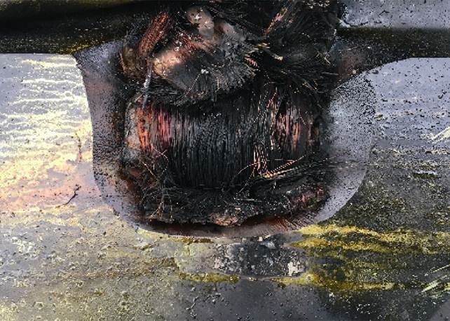
图4 F配电所计量柜线路计量电压互感器烧损情况
Fig.4 The damage of the VT in the measuring cabinet of the F power distribution station
高速铁路10 kV供电系统为中性点不接地系统,一般采用高压电缆输电,且系统电源容量足够大,可近似等效为交流恒压源EA、EB、EC。电路参数采用集总参数表示,ZA、ZB、ZC为各相线路阻抗,ZLA、ZLB、ZLC为各相负载阻抗,电缆相间分布电容分别为CAB、CBC、CCA,各相电缆对地分布电容为CN。配电所母线安装一次侧星形接地VT,其二次绕组包括一组星形联结不接地绕组(提供母线电压测量信号)和一组开口三角形联结绕组(用于零序保护),如图5所示。
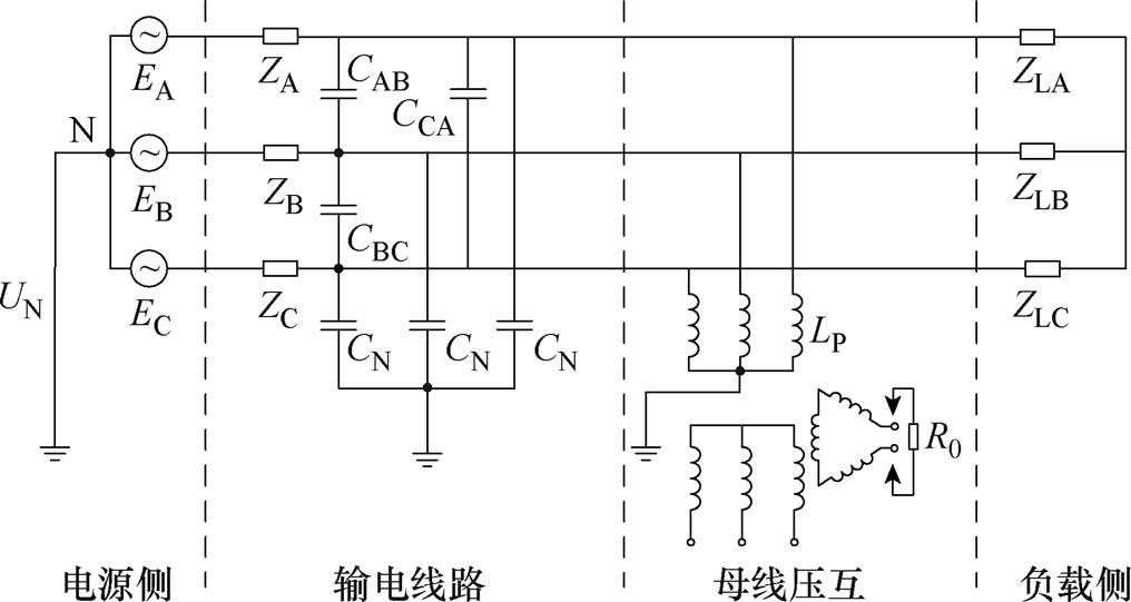
图5 高速铁路10 kV供电系统的电路
Fig.5 Schematic circuit diagram of 10 kV electric power supply system for high-speed railway
在综合考虑与铁磁谐振关系密切因素的基础上,对高速铁路10 kV供电系统电路模型进行如下简化和等效:
(1)由于VT励磁电流或磁场强度增大时,励磁电感的值将随着磁饱和呈现出显著的非线性特 性[27],所以在分析VT时可忽略二次绕组,仅考虑一次侧磁饱和特性和磁滞损耗特性,将其用一个非线性励磁电感L与铁损电导G0的并联来表示,其中L的磁通链为y。
(2)高速铁路10 kV供电系统一般采用单芯电缆或者三芯电缆,电路阻抗很小可忽略,负载阻抗与VT过电压的形成关系不大,所以只考虑线路相间电容、对地电容和VT铁磁非线性特性的影响。
基于以上考虑,当系统受到外界较大扰动,如断路、短路、分合闸操作、雷电冲击、接地故障等,绕组会产生不同程度的磁饱和现象,导致中性点偏移,造成过电压E。绕组磁饱和后,非线性电感量变小,结合系统对地电容、相间电容,如参考文献[11, 17]指出,系统电路可简化成图6所示的电路模型。
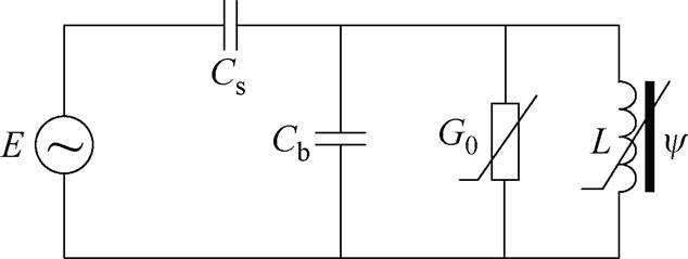
图6 高速铁路10 kV供电系统电路模型
Fig.6 The circuit model of 10 kV power supply system of high-speed railway
由于供电线路一般采用交联聚乙烯电缆,根据三芯同缆或单芯方式以及电缆长度、受扰动方式不同(断路、短路、重合闸等),同时考虑VT杂散电容[28],供电线缆对地及相间分布电容参数可在pF~mF范围。根据文献[29]及询问电压互感器厂家得知:10 kV电压互感器表示铁心损耗的励磁电阻在MW 数量级,所以忽略磁滞损耗非线性特性,铁损电导G取值为4.15×10⁻⁷ S。
本文电路模型中使用的电路参数见表1,其中w 为角频率。
表1 电路参数
Tab.1 Circuit parameters
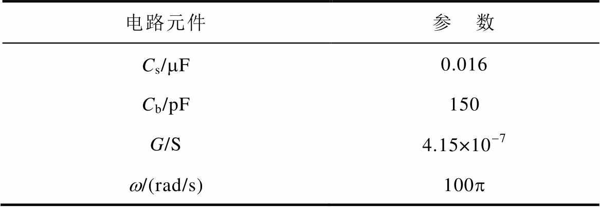
电路元件参 数 Cs/mF0.016 Cb/pF150 G/S4.15×10-7 w/(rad/s)100p
运用戴维南定理对图6进行等效变换,开路电压为uo,等效电容为Ceq,其等效关系分别为
 (1)
(1)
 (2)
(2)
式中,Em为激励源E的过电压幅值。
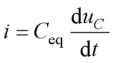
进一步简化,得到图7所示电路简化模型,其中等效电容Ceq两端电压为uC,非线性电感L两端电压为u,通过VT的电流i由表示励磁电感主饱和特性的电流is、表示铁心损耗的磁滞电流ih两部分构成。
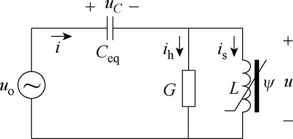
图7 高速铁路10 kV供电系统简化模型
Fig.7 Simplified model of the 10 kV power supply system of high-speed railway
根据图7及根据电路元件的电压、电流及磁链之间的关系,可得
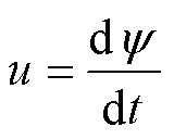 (3)
(3)
 (4)
(4)
 (5)
(5)
非线性电感主饱和磁通-电流曲线可以用n阶奇次多项式is=f(y)表示[2],即
 (6)
(6)
式中,n为奇数(一般取3、5、9、11),本文结合工程实际取5;a和b为电压互感器参数,其值由电压互感器实测伏安特性数据,并采用最小二乘法拟合确定[2, 30],可得a=8.6×10⁻⁵,b=7.3×10⁻¹¹。
磁滞电流近似等于铁心损耗电流,即
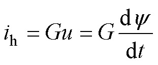 (7)
(7)
因此,磁化电流为
 (8)
(8)
故电容电流为
 (9)
(9)
联合式(1)、式(3)、式(9)可得
 (10)
(10)
联立式(3)和式(10),可得描述高速铁路10 kV供电系统状态方程为
 (11)
(11)
显然,式(11)是含有外施激励源的二阶非自治非线性周期时变系统。
由于未知量u是y 的导数,可将式(11)改写为
 (12)
(12)
式(12)的解必然是周期解,可将 近似表示为傅里叶级数为
 (13)
(13)
式中,K取自然数,根据系统周期解的谐波含量和精度要求来确定,一般K取值越大,精度越高。
若定义

 (14)
(14)
 (15)
(15)
则有
 (16)
(16)
 (17)
(17)
 (18)
(18)
由式(12)、式(16)、式(17)、式(18)可得

 (19)
(19)
基于三角函数的正交性,对式(19)两边在一个周期内求积分,即
 (20)
(20)
求解上述2K+1个代数方程组,便可得到a0, a1, a2,…, aK, b1, b2, b3,…, bK,即得到 的近似解。
的近似解。
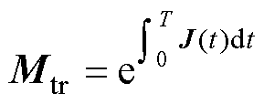
根据Floquet理论[31],对于周期时变系统,可通过系统转移矩阵Mtr的特征值(即Floquet乘子)与以复平面原点为中心的单位圆的相对关系来分析判断系统解的稳定性。
 (21)
(21)
式中,T为系统稳态时的周期,T=2p;J(t)为系统雅克比矩阵,表示为
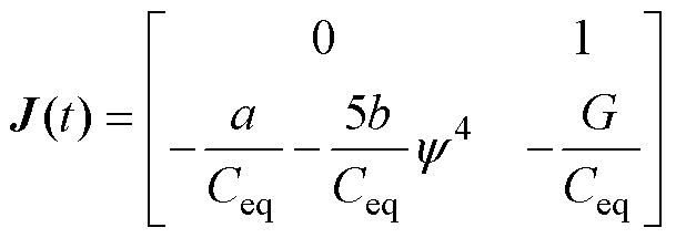 (22)
(22)
若所有Floquet乘子均位于单位圆内,则周期解是稳定的。否则周期解不稳定,即出现了分岔。Floquet乘子与系统分岔行为之间存在三种关系[31]:
(1)1个实Floquet乘子沿着负实轴穿越单位圆,而其他乘子均在单位圆内,则系统将发生倍周期 分岔。
(2)1个实Floquet乘子沿着正实轴穿越单位圆,而其他乘子均在单位圆内,则系统将发生鞍结分岔。
(3)1对共轭复数Floquet乘子穿越单位圆,而其他乘子均在单位圆内,则系统发生Hopf分岔。
转移矩阵Mtr是时变矩阵,其关于时间t是连续的,为了计算铁磁系统转移矩阵Mtr的特征值,将系统稳态时的周期[0, T]分为M个子区间,每个子区间的长度为
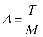 (23)
(23)
而第m个子区间的起始时间为
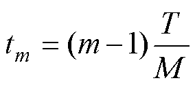 (24)
(24)
因此,当M足够大时,可以将转移矩阵Mtr(t)视为第m个子区间中的常数,并可用其在此区间中的平均值代替,因此有
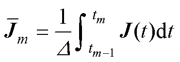 (25)
(25)
所以,转移矩阵Mtr可以表示为
 (26)
(26)
其中
 (27)
(27)
所以,系统转移矩阵Mtr的Floquet乘子为
 (28)
(28)
基于式(28)计算得到的转移矩阵Mtr的Floquet乘子与复平面单位圆的关系,可判断系统的稳定性并识别系统的分岔类型。
10 kV系统是中性点不接地系统,当受到扰动(如断路、短路、重合闸等),造成三相电压互感器某些相铁磁饱和,从而致使中性点偏移形成过电压,过电压是实际工程应用中导致铁磁谐振现象发生的重要因素。本节在其他电路参数不变的情况下,分析系统激励幅值Em变化对系统稳定性的影响,定量计算系统分岔点及分岔类型,并且分析当其他参数如Cs、Cb变化后对Em与系统分岔相关性的影响。
当Em取8.165 kV时系统稳态运行,非线性电感磁通链y 其解为稳态周期解。注意,K取2,且采用改进差分进化算法求解基于谐波平衡法和三角函数正交性构建的代数方程组,得到的系统磁链y 的近似解析解为
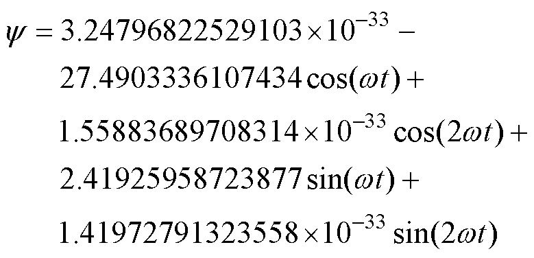 (29)
(29)
图8表示基于谐波平衡法简化模型的近似解析解和模型数值计算的数值解之间的比较,可见两者结果一致,图8表明采用谐波平衡法可有效地计算高速铁路10 kV供电系统模型的近似周期解。
根据式(26),M取4 000,求得系统在表1参数条件下转移矩阵Mtr的Floquet乘子。当工作电源Em=8.165 kV,转移矩阵Mtr的Floquet乘子为
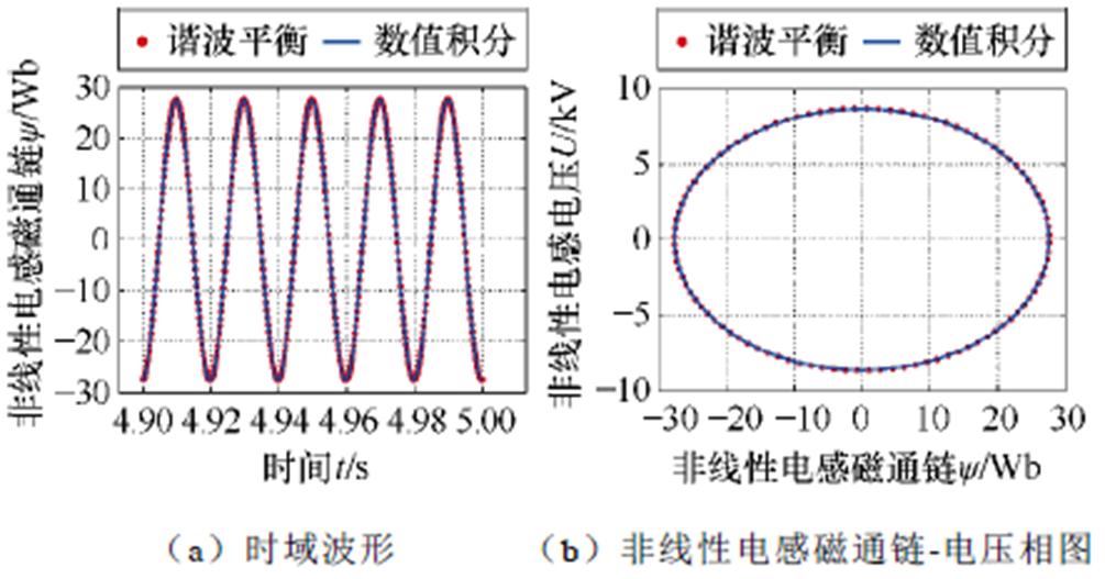
图8 系统稳定运行时采用数值积分完整模型(实线)和采用谐波平衡法简化模型(虚线)解的对比
Fig.8 Comparison of the solution of the numerical integral complete model (solid line) and the simplified model (dashed line) by harmonic balance method when the system is stable
 (30)
(30)
由式(30)可知,两个Floquet乘子均在单位圆内,表明系统在该条件下是稳定的。同理,逐渐增大Em,计算出不同Em下的特征值,如表2和图9所示。由表2和图9可以看到,当Em≤12.238 kV时,系统能够在工频下稳定运行。但是,随着激励源幅值的逐渐增加,Floquet乘子由一对实数逐渐增大、虚数逐渐减小的共轭复数变为两个独立实数,其中一个实Floquet乘子沿着正方向逐渐增大并移出单位圆,另一个Floquet乘子留在单位圆内且逐渐减小。根据3.1节中所述Floquet乘子与系统分岔行为之间存在的三种关系,由于鞍结分岔的发生,导致系统产生铁磁谐振现象。
表2 不同激励幅值Em下的Floquet乘子
Tab.2 Characteristic roots of different excitation Em
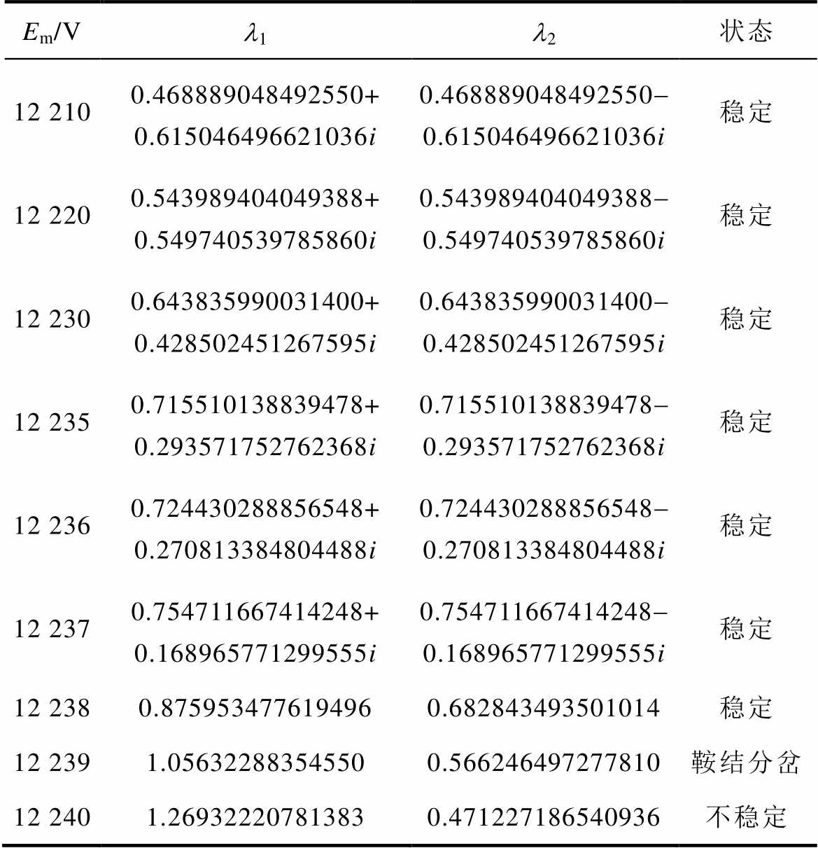
Em/Vl1l2状态 12 2100.468889048492550+ 0.615046496621036i0.468889048492550- 0.615046496621036i稳定 12 2200.543989404049388+ 0.549740539785860i0.543989404049388- 0.549740539785860i稳定 12 2300.643835990031400+ 0.428502451267595i0.643835990031400- 0.428502451267595i稳定 12 2350.715510138839478+ 0.293571752762368i0.715510138839478- 0.293571752762368i稳定 12 2360.724430288856548+ 0.270813384804488i0.724430288856548- 0.270813384804488i稳定 12 2370.754711667414248+ 0.168965771299555i0.754711667414248- 0.168965771299555i稳定 12 2380.8759534776194960.682843493501014稳定 12 2391.056322883545500.566246497277810鞍结分岔 12 2401.269322207813830.471227186540936不稳定
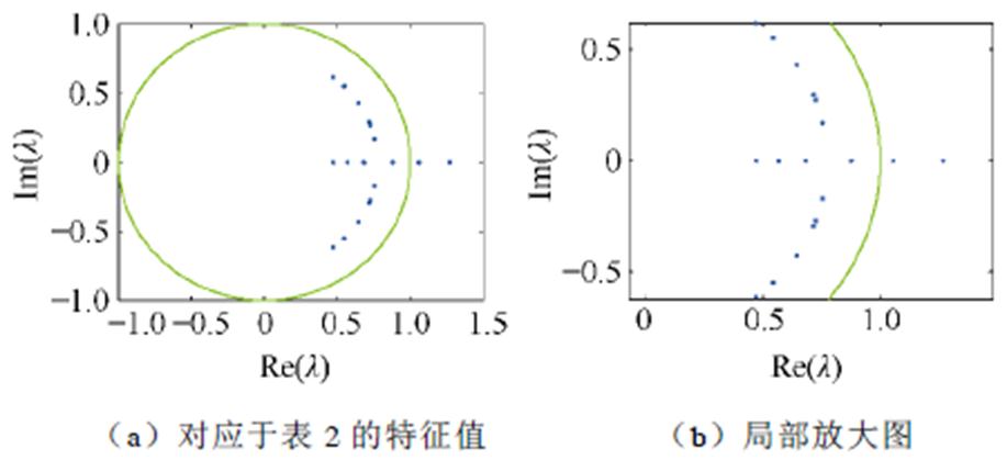
图9 激励幅值增大时Mtr的Floquet乘子轨迹
Fig.9 The eigenvalue locus of Mtrwhen the excitation amplitude increases
此外,当Cs为10 nF和16 nF两种情况下,Cb分别取不同值时,可同理分析系统出现分岔所对应的激励幅值Em的变化情况,见表3。
表3 不同Cs下系统随Cb变化出现分岔时的Em
Tab.3 Bifurcation points with Cb and Em change in different Cs conditions
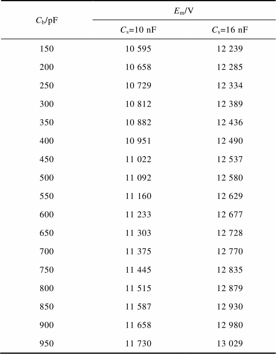
Cb/pFEm/V Cs=10 nFCs=16 nF 15010 59512 239 20010 65812 285 25010 72912 334 30010 81212 389 35010 88212 436 40010 95112 490 45011 02212 537 50011 09212 580 55011 16012 629 60011 23312 677 65011 30312 728 70011 37512 770 75011 44512 835 80011 51512 879 85011 58712 930 90011 65812 980 95011 73013 029
根据表3可得系统多维参数空间稳定边界曲线,如图10所示。显然,当Cs一定时,系统稳定域随着Cb的增大而增大;而当Cb值一定时,Cs较大时系统的稳定域也较大。
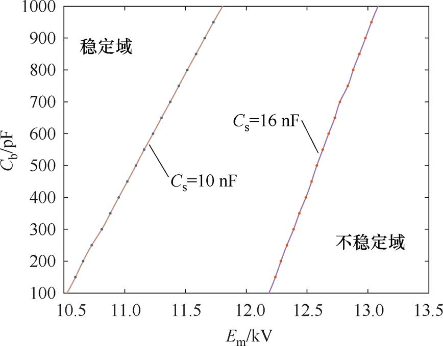
图10 不同Cs条件下随Cb、Em二维参数变化时系统的稳定边界及稳定域
Fig.10 Stability boundary and stability region of the system with the two-dimensional parameters of Cb and Em under different Cs conditions
上述内容清晰地阐释了高速铁路10 kV供电系统铁磁谐振产生的物理机理,即是由于系统发生了鞍结分岔而导致的。但在工程应用中,电气工程师也需要确定与系统稳定性有关的关键参数。
对于本文研究的高速铁路10 kV供电系统,可通过计算Floquet乘子敏感值来判断与系统稳定性有关的关键参数,其Floquet乘子敏感值的计算公式[32]为
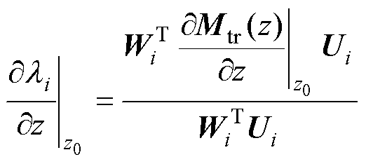 (31)
(31)
式中,z为系统参数,如Cs、Cb、G、a、b;z0为系统平衡点处的系统参数;Mtr(z)为转移矩阵; 和Ui为Floquet乘子
 对应的左特征向量和右特征向量。
将式(25)、式(26)代入式(31)可计算出不同系统参数z的一阶Floquet乘子敏感值。Em取工作电压8.165 kV时的计算结果见表4。
Floquet乘子敏感值实部的大小和符号分别表示在系统参数z0上叠加小扰动时,Floquet乘子li在复平面单位圆水平方向上移动的速度和方向,而Floquet乘子敏感值虚部表示Floquet乘子li在复平面单位圆垂直方向的运动情况。由表4可知,除了参数b外,参数Cb、Cs、G、a所对应的Floquet乘子敏感值都比较大。所以,对于高速铁路10 kV供电系统,参数Cb、Cs、G、a的变化都比较容易导致系统的Floquet乘数向复平面单位圆外移动,从而使系统发生分岔,且参数Cb的变化对系统的分岔行为影响最大。
表4 不同系统参数的一阶Floquet乘子值
Tab.4 First-order Floquet multiplier sensitivity of different system parameters
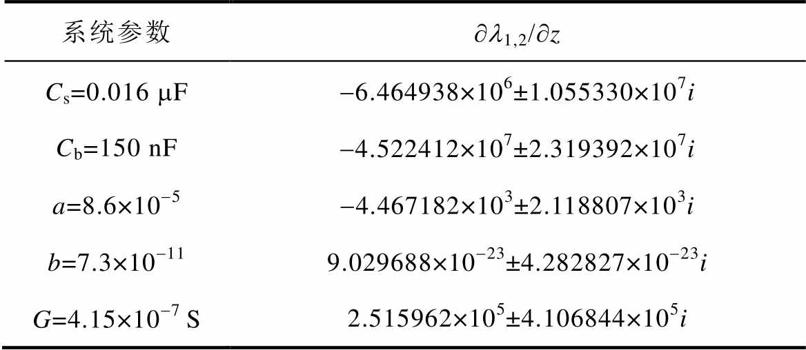
系统参数∂l1,2/∂z Cs=0.016 mF-6.464938×10⁶±1.055330×10⁷i Cb=150 nF-4.522412×10⁷±2.319392×10⁷i a=8.6×10⁻⁵-4.467182×10³±2.118807×10³i b=7.3×10-119.029688×10⁻²³±4.282827×10⁻²³i G=4.15×10⁻⁷ S2.515962×105±4.106844×10⁵i
基于ATPDraw电路仿真软件,以非线性电感L98和电阻搭建了与本文数学模型一致的具有非线性磁饱和特性和线性磁滞特性的电磁式电压互感器模型,非线性电感磁链-电流特性采用分段线性化表示,ATPDraw下高速铁路10 kV供电系统模型如图11所示,图中U为非线性电感两端电压,I为流过非线性电感的电流。
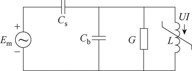
图11 ATPDraw下高速铁路10 kV供电系统模型
Fig.11 The circuit model of the 10 kV power supply system of high-speed railway in ATPDraw
在表1所示电路参数下,当选择Em=8.165 kV和Em=12.250 kV时,分别采用数值计算和ATPDraw电路仿真,得到非线性电感电压的时域波形及其相应的快速傅里叶变换(Fast Fourier Transformation, FFT)分析结果如图12和图13所示。由图12可知,当系统稳定运行时,电压几乎只含有基频分量;由图13可知,当Em为12.250 kV时,系统发生铁磁谐振,电压除基波外,还含有大量奇次谐波,以基波含量为基准,其3次、5次、7次及9次谐波标幺值分别为0.321 97(pu)、0.089 87(pu)、0.022 70(pu)、0.005 74(pu)。
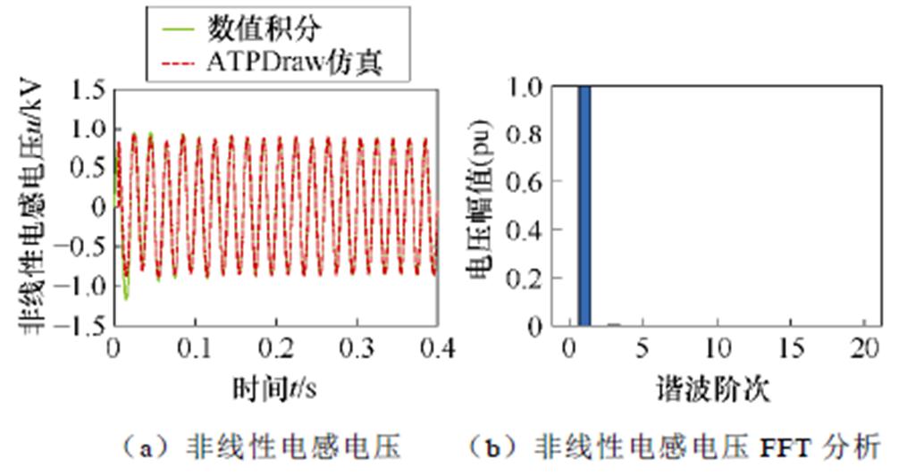
图12 Em取8.165 kV时ATPDraw电路仿真结果与数值计算对比及FFT分析
Fig.12 ATPDraw circuit simulation results compared with numerical calculation and FFT analysis when Em is 8.165 kV
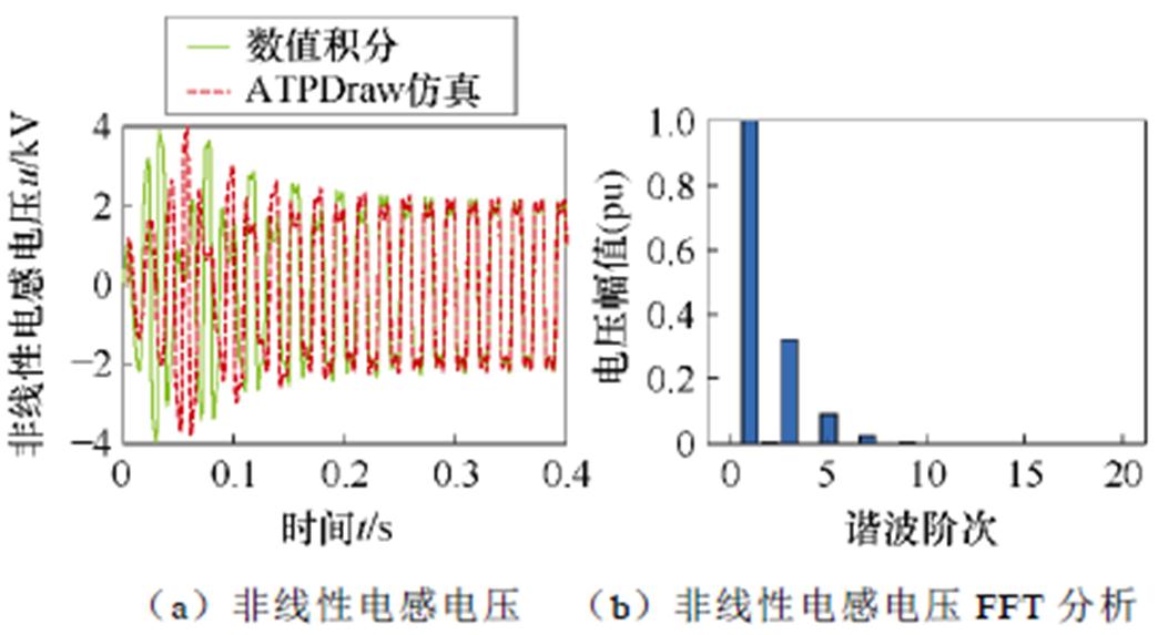
图13 Em取12.250 kV时ATPDraw电路仿真结果与数值计算对比及FFT分析
Fig.13 ATPDraw circuit simulation results compared with numerical calculation and FFT analysis when Em is 12.250 kV
另外,在ATPDraw环境下对系统进行电路仿真,当Cs分别取16 nF和10 nF时,逐渐增大Cb参数值,记录系统出现分岔时的激励幅值Em,并绘制分岔点,如图14所示。
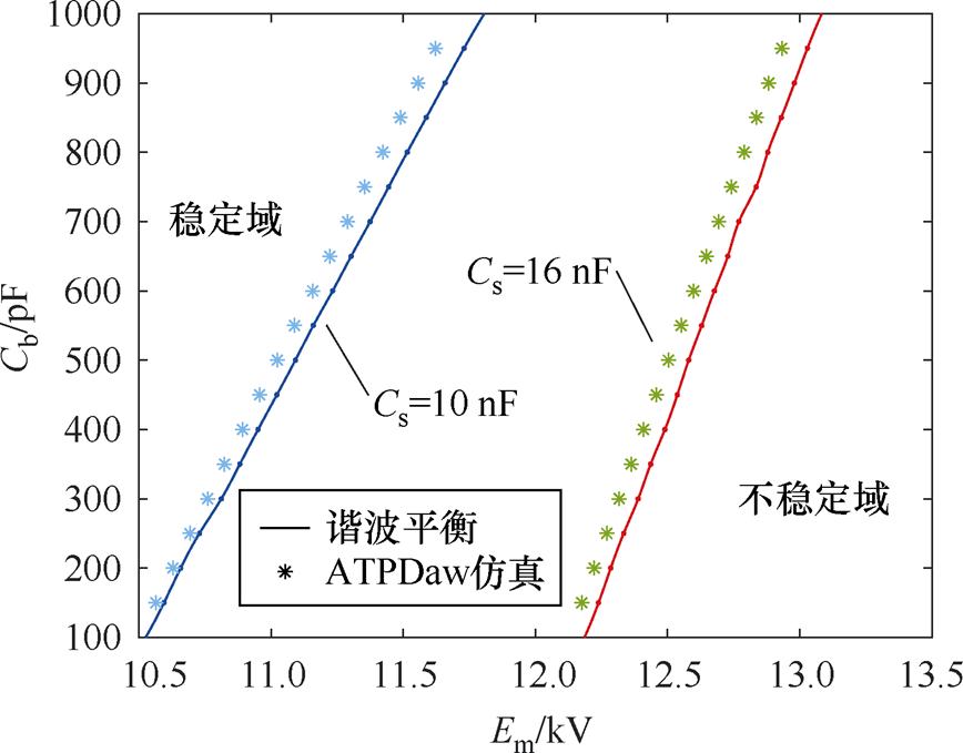
图14 谐波平衡法(实线)和电路仿真(星号)在参数空间中的稳定性边界对比
Fig.14 Stability boundary comparison between harmonic balance method (solid line) and circuit simulation (asterisk) in parameter space
根据图12~图14可知,系统数值仿真结果与在ATPDraw环境下的电路仿真结果基本一致,从而验证了采用谐波平衡法和Floquet理论可有效地分析高速铁路10 kV供电系统中的铁磁谐振现象,并可清晰地揭示该系统发生铁磁谐振现象是由于系统出现鞍结分岔而导致的。
铁路10 kV供电系统是含有时变激励的非线性非自治系统,本文以高速铁路10 kV供电系统为研究对象,考虑系统中电压互感器的非线性特性,建立系统数学模型,并运用Floquet理论识别其周期解的稳定性,揭示其出现铁磁谐振是由于系统随着激励幅值增大发生了鞍结分岔。文中还分析了系统参数变化对系统铁磁谐振的影响,并通过数值计算和ATPDraw环境下电路仿真对理论分析进行了验证。本文研究对于具有铁磁饱和特性的10 kV供电系统在运行参数范围内的稳定性分析、稳定域的判定以及系统稳定性对相关参数的敏感度分析具有一定工程应用价值。
参考文献
[1] Tran-Quoc T, Pierrat L. An efficient non linear transformer model and its application to ferrore- sonance study[J]. IEEE Transactions on Magnetics, 1995, 31(3): 2060-2063.
[2] 韩国强, 刘相龙, 赵一龙, 等. 中性点不接地配电系统并联铁磁谐振状态频域解析方法[J]. 电气技术, 2020, 21(10): 88-92.
Han Guoqiang, Liu Xianglong, Zhao Yilong, et al. Frequency domain analytical method for parallel ferroresonance state of distribution system with neutral point ungrounded[J]. Electrical Engineering, 2020, 21(10): 88-92.
[3] 华超, 周岩, 胡震, 等. 基于移相调制的无线供电与信息协同传输技术[J]. 电工技术学报, 2023, 38(16): 4233-4245.
Hua Chao, Zhou Yan, Hu Zhen, et al. Simultaneous wireless power and information transmission method based on phase-shifted modulation[J]. Transactions of China Electrotechnical Society, 2023, 38(16): 4233- 4245.
[4] Wei Jufang, Feng Junji, Yao Chuang, et al. Fault analysis of 10 kV voltage transformer using the “4PT” method[C]//2021 International Conference on Control Science and Electric Power Systems (CSEPS), Shanghai, China, 2021: 368-371.
[5] 周丽霞, 尹忠东, 郑立. 配网PT铁磁谐振机理与抑制的试验研究[J]. 电工技术学报, 2007, 22(5): 153-158.
Zhou Lixia, Yin Zhongdong, Zheng Li. Research on principle of PT resonance in distribution power system and its suppression[J]. Transactions of China Electrotechnical Society, 2007, 22(5): 153-158.
[6] 朱学成, 张德文, 董尔佳, 等. 发变组冲击跳闸铁磁谐振故障仿真分析[J]. 湖北电力, 2020, 44(6): 69-74.
Zhu Xuecheng, Zhang Dewen, Dong Erjia, et al. Simulation analysis on ferromagnetic resonance fault of generator-transformer unit impact trip[J]. Hubei Electric Power, 2020, 44(6): 69-74.
[7] 曹斌, 张鹏, 陈波, 等. 基于PSCAD的500kV自耦变压器铁磁谐振过电压仿真[J]. 高压电器, 2015, 51(12): 155-161.
Cao Bin, Zhang Peng, Chen Bo, et al. Simulation of ferroresonance overvoltage caused by commissioning 500kV auto-transformer based on the pscad[J]. High Voltage Apparatus, 2015, 51(12): 155-161.
[8] 王泽忠, 司远, 刘连光. 地磁暴对电力系统稳定性的影响[J]. 电工技术学报, 2022, 37(7): 1780-1788.
Wang Zezhong, Si Yuan, Liu Lianguang. Influence of geomagnetic storms on the stability of power system[J]. Transactions of China Electrotechnical Society, 2022, 37(7): 1780-1788.
[9] 许贵民, 姚帅, 尹红霞. 中性点非有效接地系统电磁式电压互感器铁磁谐振问题研究[J]. 电气应用, 2020, 39(5): 53-60.
Xu Guimin, Yao Shuai, Yin Hongxia. Comprehensive analysis on ferroresonance of electromagnetic potential transformer for power system with invalid neutral grounding modes[J]. Electrotechnical Appli- cation, 2020, 39(5): 53-60.
[10] 魏菊芳, 唐庆华, 王飞, 等. 小电流接地系统电压互感器铁磁谐振过电压与抑制措施仿真分析[J]. 电网与清洁能源, 2015, 31(12): 48-56.
Wei Jufang, Tang Qinghua, Wang Fei, et al. Simulation analysis for ferromagnetic resonance of potential transformer and restraining measures in small current neutral grounding system[J]. Power System and Clean Energy, 2015, 31(12): 48-56.
[11] 肖洪生. 图解法解工频铁磁谐振过电压[J]. 吉林电力技术, 1983, 11(2): 45-50, 24.
Xiao Hongsheng. Graphic solution of power frequency ferromagnetic resonance overvoltage[J]. Jilin Electric Power, 1983, 11(2): 45-50, 24.
[12] 陈昌鹏, 朱松. 配电系统铁磁谐振分析[J]. 东北电力技术, 2012, 33(7): 35-38.
Chen Changpeng, Zhu Song. Distribution system ferroresonance analysis[J]. Northeast Electric Power Technology, 2012, 33(7): 35-38.
[13] 刘宝稳, 曾祥君, 张慧芬, 等. 不平衡零序电压快速精准抑制与电压消弧全补偿优化控制方法[J]. 电工技术学报, 2022, 37(3): 645-654.
Liu Baowen, Zeng Xiangjun, Zhang Huifen, et al. Optimal control method for accurate and fast suppression of unbalanced zero-sequence voltage and voltage arc suppression full compensation[J]. Transa- ctions of China Electrotechnical Society, 2022, 37(3): 645-654.
[14] 亓志滨, 田君杨, 薛永端, 等. 不接地系统异名相两点接地故障工频电气量及其对选线的影响分析[J]. 电工技术学报, 2023, 38(13): 3539-3551.
Qi Zhibin, Tian Junyang, Xue Yongduan, et al. Analysis of power frequency electrical quantity and line selection applicability for two-point grounding faults occurring on different phases in isolated neutral system[J]. Transactions of China Electrotechnical Society, 2023, 38(13): 3539-3551.
[15] 李国庆, 彭石, 张少杰, 等. 变压器与并联电容器的铁磁谐振分析[J]. 电力系统保护与控制, 2014, 42(9): 26-32.
Li Guoqing, Peng Shi, Zhang Shaojie, et al. Analysis of ferromagnetic resonance between transformer and shunt capacitor[J]. Power System Protection and Control, 2014, 42(9): 26-32.
[16] 崔巨勇, 王帅, 赵子健, 等. 电磁式电压互感器铁磁谐振特性分析[J]. 电器与能效管理技术, 2023(1): 62-65, 77.
Cui Juyong, Wang Shuai, Zhao Zijian, et al. Analysis of electromagnetic voltage transformer ferroresonance characteristics[J]. Electrical & Energy Management Technology, 2023(1): 62-65, 77.
[17] 刘凡, 孙才新, 司马文霞, 等. 铁磁谐振过电压混沌振荡的理论研究[J]. 电工技术学报, 2006, 21(2): 103-107.
Liu Fan, Sun Caixin, Sima Wenxia, et al. Theoretical analysis of chaotic oscillation of ferroresonance overvoltage in power systems[J]. Transactions of China Electrotechnical Society, 2006, 21(2): 103-107.
[18] Radmanesh H, Nademi M, Nademi M. Circuit breaker shunt resistance effect on ferroresonancein voltage transformer including nonlinear core losses[J]. International Journal of Computer and Electrical Engineering, 2012: 743-747.
[19] 庞霞, 刘崇新. 含电磁式电压互感器的铁磁混沌电路的分析研究[J]. 物理学报, 2013, 62(15): 60-65.
Pang Xia, Liu Chongxin. Analysis of ferromagnetic chaotic circuit with nonlinear potential transformer[J]. Acta Physica Sinica, 2013, 62(15): 60-65.
[20] 代姚, 司马文霞, 孙才新, 等. 应用T-S模糊方法对铁磁谐振过电压的混沌抑制[J]. 高电压技术, 2010, 36(4): 878-883.
Dai Yao, Sima Wenxia, Sun Caixin, et al. Chaos controlling in ferroresonance overvoltage with T-S fuzzy method[J]. High Voltage Engineering, 2010, 36(4): 878-883.
[21] Hui Meng, Liu Chongxin. Effect of power frequency excitation character on ferroresonance in neutral- grounded system[J]. Chinese Physics B, 2010, 19(12): 120509.
[22] Milicevic K, Emin Z. Initiation of characteristic ferroresonance states based on flux reflection model[J]. IEEE Transactions on Circuits and Systems II: Express Briefs, 2013, 60(1): 51-55.
[23] Mork B A, Stuehm D L. Application of nonlinear dynamics and chaos to ferroresonance in distribution systems[J]. IEEE Transactions on Power Delivery, 1994, 9(2): 1009-1017.
[24] 李其莹. 中性点不接地系统铁磁谐振的并联电路计算模型与诊断方法[J]. 变压器, 2019, 56(2): 34-38.
Li Qiying. Parallel circuit calculation model and diagnostic method of ferroresonance for neutral ungrounded system[J]. Transformer, 2019, 56(2): 34-38.
[25] 王宾, 张超, 丁心志. 中性点直接接地系统单相串联铁磁谐振时域解析分析[J]. 中国电机工程学报, 2022, 42(6): 2124-2133.
Wang Bin, Zhang Chao, Ding Xinzhi. Time domain analytical analysis of single-phase series ferro- magnetic resonance in neutral point solid grounding power system[J]. Proceedings of the CSEE, 2022, 42(6): 2124-2133.
[26] 张超, 王宾, 张海, 等. 中性点直接接地电网单相串联铁磁谐振检测与类型辨识[J]. 电力系统自动化, 2022, 46(19): 172-179.
Zhang Chao, Wang Bin, Zhang Hai, et al. Detection and type identification of single-phase series ferro- resonance in neutral point solid grounding power grid[J]. Automation of Electric Power Systems, 2022, 46(19): 172-179.
[27] 冯慈璋, 马西奎. 工程电磁场导论[M]. 北京: 高等教育出版社, 2000.
[28] 沈泽亮, 汪金刚, 王谦, 等. 一种基于低频窄带扫描的电磁式电压互感器杂散电容测量与精确建模方法[J]. 电工技术学报, 2023, 38(8): 2211-2221.
Shen Zeliang, Wang Jingang, Wang Qian, et al. A method for stray capacitance measuring and refined modeling of potential transformer based on low frequency and narrow band scanning[J]. Transactions of China Electrotechnical Society, 2023, 38(8): 2211- 2221.
[29] Rezaei-Zare A, Iravani R, Sanaye-Pasand M. Impacts of transformer core hysteresis formation on stability domain of ferroresonance modes[J]. IEEE Transa- ctions on Power Delivery, 2009, 24(1): 177-186.
[30] 丛伟, 孙允, 路庆东, 等. 电压互感器励磁特性曲线拟合的复合解法[J]. 电力系统保护与控制, 2013, 41(12): 60-64.
Cong Wei, Sun Yun, Lu Qingdong, et al. Comprehensive solving method for the fitting of electromagnetic PT excitation characteristic[J]. Power System Protection and Control, 2013, 41(12): 60-64.
[31] Wang Faqiang, Zhang Hao, Ma Xikui. Analysis of slow-scale instability in Boost PFC converter using the method of harmonic balance and Floquet theory[J]. IEEE Transactions on Circuits and Systems I: Regular Papers, 2010, 57(2): 405-414.
[32] Zhang Hao, Dong Shuai, Zhang Yuan, et al. Intermediate-frequency oscillation behavior of one- cycle controlled SEPIC power factor correction converter via Floquet multiplier sensitivity analysis[J]. International Journal of Bifurcation and Chaos, 2016, 26(10): 1650163.
Mechanism Analysis of Ferroresonance in 10 kV Power Supply System for High-Speed Railway Based on Harmonic Balance Method and Floquet Theory
Abstract 10 kV power supply system of high-speed railway is a neutral ungrounded system. Ferromagnetic saturation in the phase of electromagnetic voltage transformers (VT) can cause overvoltage due to the neutral offset when the system is disturbed by open circuit, short circuit, and reclosing. With the increase of excitation or magnetic field intensity of the VT, the excitation inductance exhibits significant nonlinear characteristics with magnetic saturation. In this scenario, the secondary winding can be ignored, and the primary side’s magnetic saturation and hysteresis loss characteristics are considered. Therefore, this system is a typical nonlinear, non-autonomous system with time-varying excitation, rich in complex nonlinear phenomena like ferroresonance.
In the paper, VT is represented by the parallel connection of nonlinear inductance L and iron loss conductance G. The principal saturation flux-current curve of the nonlinear inductance can be expressed by the polynomial is=aj+bj n, where n is taken as 5 based on the actual engineering, a is 8.6×10⁻⁵, and b is 7.3×10⁻¹¹ from the measured volt-ampere characteristic data of the voltage transformer.
This paper forms a simplified circuit model containing excitation source uo, series capacitance Ceq, excitation conductance G, and nonlinear inductance L. The state equation of the system is established with the nonlinear inductance flux j and voltage u as the state variables using Thevenin's theorem. Then, based on the orthogonality of the trigonometric function, the harmonic balance method solves the periodic approximate solutions of the system under different parameters, and the periodic Jacobian matrix J(t) of the system under the parameters is derived. On this basis, J(t) is piecewise integrated, and its average value in the m-th section  is obtained. The transfer matrix Mtr of the system and the eigenvalue of Mtr (i.e., the Floquet multiplier) can be obtained conveniently.
There are three kinds of relations between Floquet multiplier and bifurcation behavior of the nonlinear system, according to which the stability of periodic solution can be identified. The calculation shows that with the gradual increase of the excitation, the Floquet multiplier is changed from a conjugate complex number to independent real numbers with a pair of real numbers gradually increasing and imaginary numbers decreasing. Herein, one real Floquet multiplier gradually increases in the positive direction and moves out of the unit circle, the other remains in the unit circle and gradually decreases, and the saddle junction bifurcation occurs, leading to ferroresonance. With the change of series and parallel capacitance of the saturated phase, the critical excitation amplitude Em for maintaining stable operation of the system changes. Furthermore, the stability region of spatial parameters under different conditions can be obtained. The paper also gives the critical parameters related to the stability of the system through sensitivity analysis and mathematical calculating for this system’s parameter design.
Finally, the circuit simulation results in ATPDraw align with the theoretical calculation. Therefore, the ferroresonance phenomenon in the 10 kV power supply system of the high-speed railway can be effectively analyzed using the harmonic balance method and Floquet theory. In conclusion, this study has practical value in the prevention and elimination of ferroresonance in neutral ungrounded systems containing electromagnetic voltage transformers.
Keywords:Ferroresonance, nonlinear, harmonic balance, saddle-node bifurcation
中图分类号:TM71
DOI: 10.19595/j.cnki.1000-6753.tces.231153
收稿日期 2023-07-18
改稿日期 2023-08-16
王 显 男,1986年生,博士,研究方向为铁道牵引供电。
E-mail: wangxian@stu.xjtu.edu.cn
王发强 男,1980年生,副教授,博士生导师,研究方向为电力电子建模、分析和控制。
E-mail: faqwang@mail.xjtu.edu.cn(通信作者)
(编辑 郭丽军)