 变化。根据法拉第电磁感应定律,检测线圈两端产生的感应电压
 可表示为[19]
摘要 磁致伸缩位移传感器在检测线圈附近存在测量盲区,在受限安装空间内有效测量范围难以满足应用需求。针对这一问题,基于魏德曼效应、磁弹性耦合效应和维拉里效应,建立合成磁场作用下磁致伸缩位移传感器的测量盲区模型,分析测量盲区内传感器失效机理。搭建实验平台提供可调的脉冲电流和轴向磁场,选用直径为0.6 mm的(Fe83Ga17)99.4B0.6、Fe46.5Ni48.5Cr2Ti2.5Al0.5和Fe30Co70波导丝验证模型的准确性,测量盲区受永磁体产生的轴向磁场影响,并且随轴向磁场增大。增加静磁屏蔽装置并确定最佳参数,制作样机并测试表明:优化后的(Fe83Ga17)99.4B0.6波导丝传感器测量盲区由30.05 μs缩短为18.45 μs,宽度缩短了38.6%;Fe46.5Ni48.5Cr2Ti2.5Al0.5波导丝传感器测量盲区由31.15 μs缩短为19.15 μs,宽度缩短了38.5%;Fe30Co70波导丝传感器测量盲区由29.55 μs缩短为18.85 μs,宽度缩短了36.2%。
关键词:磁致伸缩位移传感器 测量盲区模型 静磁屏蔽
磁致伸缩位移传感器利用魏德曼效应可以实现位移的测量,具有高精度、非接触式、高可靠性且适应于恶劣环境等特点,被广泛应用于多种领域[1-2]。由于磁致伸缩位移传感器在检测线圈附近存在测量盲区,在液压缸、机械臂等安装空间受限的领域,有效测量范围难以满足应用需求。这一问题限制了精密测量、精密位移控制[3-4]的发展。
国内外学者在磁致伸缩位移传感器原理、波导丝材料、结构优化和信息采集与处理等方面做了大量研究工作。E. Hristoforou等[5-6]解释了磁致伸缩位移传感器的工作原理,从磁化强度变化方面研究了输出电压与激励磁场之间的关系。周新志等[7]通过理论分析、实验测试和模拟分析,研究了决定魏德曼效应的要素包括磁致伸缩特性、磁滞特性以及周向和纵向磁场特性。邓超等[8]基于磁畴自由旋转效应和磁源波导效应解释了磁致伸缩位移传感器的原理,提出了使用铁磁性材料对接收线圈进行静磁屏蔽的结构。黄文美等[9-12]设计了磁致伸缩材料磁特性测试装置,在不同激励条件下,测量了不同磁致伸缩材料的动态磁特性曲线。张露予等[13-14]基于魏德曼效应和压磁效应建立了螺旋磁场作用下磁致伸缩位移传感器的输出电压模型,通过对比实验值与理论值,对模型进行了验证。王博文等[15]分析了波导丝材料、脉冲电流和检测线圈等参数对磁致伸缩位移传感器输出电压的影响,设计了一种Fe-Ga波导丝磁致伸缩位移传感器,与Fe-Ni波导丝传感器相比,前者有更高的检测电压信号幅值、信噪比以及传感器精度。谢新良等[16]对扭转波在波导丝中的衰减特性进行研究,提出无阻尼反射的检测方案,通过检测回波的幅值来测量超声波衰减系数。李媛媛等[17-18]基于材料力学求解了扭转应力,建立了扭转力作用下磁致伸缩位移传感器的输出电压模型,又针对应力波在传播过程中的衰减问题,从声压强度与声波峰值的关系出发建立了含有传播距离的输出电压模型,确定了输出电压随传播距离呈指数衰减的规律。
然而,以上研究均未建立传感器的测量盲区计算模型,未研究脉冲电流与永磁体产生的合成磁场对传感器测量盲区的影响。本文首先基于魏德曼效应、磁弹性耦合效应和维拉里效应,从理论上研究了磁致伸缩位移传感器测量盲区与合成磁场间的关系,建立了磁致伸缩位移传感器的测量盲区模型。通过测量盲区理论值与实验值的对比分析,证明了模型的正确性。其次,针对磁场影响测量盲区的问题,优化了磁致伸缩位移传感器的结构,并对其进行实验研究。优化后传感器的测量盲区得到了有效缩短,可用测量范围增加。
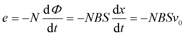
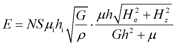
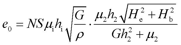
当脉冲激励电流施加在介质均匀的磁致伸缩波导丝两端时,波导丝会产生周向磁场,永磁体在波导丝处产生轴向的偏置磁场。脉冲激励电流产生的周向磁场与永磁体产生的轴向偏置磁场叠加,会产生一个合成磁场。根据魏德曼效应,磁致伸缩波导丝内部的磁畴排列状态变化,如图1所示,磁畴排列状态发生变化会引起材料内部的扭转应变,形成扭转波。根据维拉利效应,扭转波会引起磁畴的转动,使材料的磁感应强度变化。根据法拉第电磁感应定律,检测线圈两端产生的感应电压可表示为[19]
 (1)
(1)
式中,N为检测线圈匝数;S为单匝线圈面积;Φ为磁通量;B为磁感应强度;v0为扭转波的波速,室温下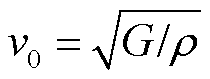 ,其中,G为材料的剪切模量,ρ为波导丝的密度。
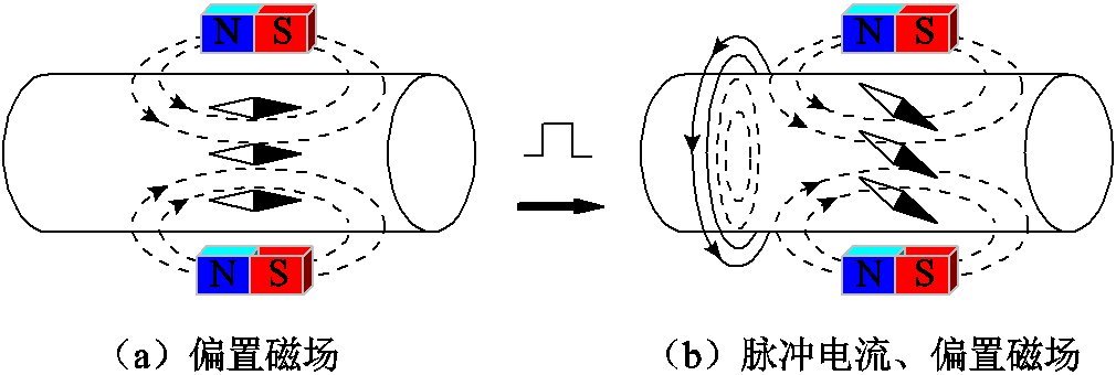
图1 磁场对波导丝磁畴排列状态的影响
Fig.1 Effect of magnetic field on the state of magnetic domain arrangement in waveguide wire
在给磁致伸缩位移传感器波导丝施加如图2a所示的脉冲激励信号后,检测线圈中会产生脉冲响应信号,如图2b所示。因为电流在检测线圈中无法突变并且时间上存在延迟,所以脉冲响应信号的电压幅值在一定的时间内会发生连续的变化,脉冲响应信号的持续时间会大于脉冲激励信号的作用时间。
图2 脉冲激励信号、脉冲响应信号和扭转波信号的波形
Fig.2 Waveforms of impulse excitation signal, impulse response signal and torsion wave signal
实验发现,当永磁体距离检测线圈较远时,脉冲响应信号保持稳定状态,扭转波信号可以被正常识别,传感器可以正常测量位移。当永磁体移动到检测线圈附近的某范围内时,脉冲响应信号会发生畸变,扭转波信号与脉冲响应信号发生重叠,扭转波信号无法被识别,导致传感器失效。此时,永磁体所处的范围就是测量盲区的范围。
在波导丝两端施加脉冲激励信号后,波导丝会产生周向磁场,根据法拉第电磁感应定律,检测线圈会产生感应电流,检测线圈的输出端输出脉冲响应电压。根据本文的脉冲响应电压模型可知,当永磁体靠近检测线圈时,永磁体产生的轴向磁场会对检测线圈产生影响,引起脉冲响应电压的变化,导致扭转波信号无法被识别,从而产生测量盲区。
根据磁致伸缩位移传感器的工作原理,测量盲区的宽度为扭转波波速与持续时间的乘积。在材料、温度等因素确定时,扭转波波速保持不变,因此以持续时间表示测量盲区。
磁致伸缩波导丝所受合成磁场中,激励磁场He由脉冲激励电流产生,偏置磁场Hz由永磁体产生。考虑到畴壁的运动和旋转,激励磁场产生的磁致伸缩波导丝的磁化过程比较复杂。由于磁致伸缩波导丝具有良好的软磁性能,为简化算法,只考虑无滞回和可逆的磁化过程。根据简化玻耳兹曼统计量[20],磁矩的统计状态由郎之万方程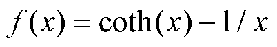 描述。磁化强度M可以表示为
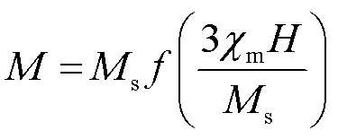 (2)
(2)
式中, 为饱和磁化强度;
 为初始线性区域磁化率。磁致伸缩材料在磁化前的内磁畴的分布是无规律的。在没有偏置磁场的情况下,磁致伸缩波导丝在受到脉冲激励信号的周向磁场时不存在扭转变形。一旦加入偏置磁场,磁畴转向外磁场方向。因此,在检测线圈处的磁致伸缩波导丝中产生了沿轴向的强感应各向异性。
当磁畴取向与外部磁场一致时,磁致伸缩系数与应变量ε为各向同性的关系[21-22],应变量表示为ε =3λsM2/(2Ms2)。其中,λs为饱和磁致伸缩系数。
由磁化强度和应变量公式可得检测线圈处的磁致伸缩应变系数h为
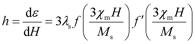 (3)
(3)
以尺寸为a×b×h的矩形永磁体的一个顶角为原点O建立如图3所示坐标系,z方向均匀、充分磁化且达到饱和状态。其空间任意一点(x, y, z)的x方向、y方向与z方向的磁场强度均可表示[23]。
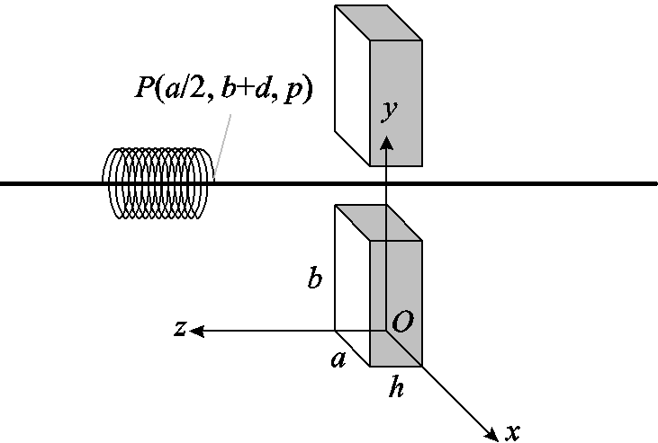
图3 永磁体结构位置示意图
Fig.3 Structural location diagram of permanent domain arrangement in waveguide wire
将沿z方向磁化的两块相同的永磁体如图3所示放置,两块永磁体同一侧的充磁方向相同,因此磁铁在波导丝上只有轴向的磁场,为了简化运算,将检测线圈等效为点P,沿波导丝轴向的磁场Hz为
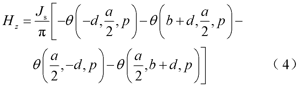
式中,d为永磁体到波导丝的垂直距离;p为检测线圈到磁铁在z轴的直线距离; 为永磁体的等效面电流密度;θ为辅助函数,其表达式为
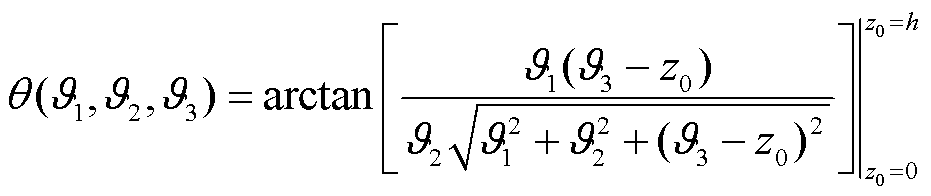 (5)
(5)
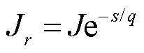
磁致伸缩波导丝上加载的脉冲激励电流持续时间为 量级,这意味着激励磁场He的存在时间极短,几乎完全存在于波导丝表面[7],在波导丝中的分布符合趋肤效应。不同的波导丝半径处的电流密度可表示为
趋肤深度q表示为
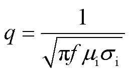
式中,s为距离波导丝表面的距离;f为脉冲激励电流频率; 为波导丝的磁导率;
 为波导丝的电导率。
波导丝表面的电流密度 可表示为
可表示为
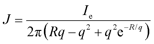 (6)
(6)
式中, 为脉冲激励电流;R为波导丝的半径。
通过波导丝的脉冲激励电流集中在趋肤深度q以内,根据安培环路定理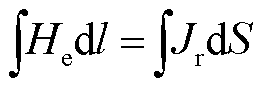 可以推出波导丝表面距离为0.5q处的激励磁场为
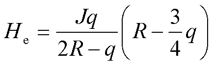 (7)
(7)
波导丝在检测线圈位置处的磁导率μ为
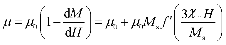 (8)
(8)
式中, 为真空磁导率。
激励磁场沿波导丝径向分布,偏置磁场沿轴向分布。合成磁场H是由激励磁场He和偏置磁场Hz耦合产生的。合成磁场可表示为 。
。
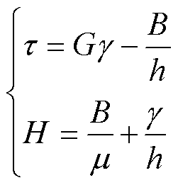
磁致伸缩材料的形变是机械能和磁场能的相互转换,利用维拉里效应可以得到线性的磁机耦合方程为
 (9)
(9)
式中,τ为磁致伸缩材料的剪切应力;G为剪切模量;γ为磁致伸缩材料的剪切应变;B为磁场变化影响的磁感应强度。
由于波导丝上不受外力作用,则剪切应力τ为零。将剪切应力τ =0和合成磁场H代入式(9),消去磁感应强度B,得到剪切应变 为
为
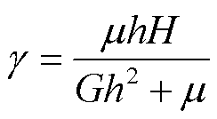 (10)
(10)
当检测线圈开路时,磁场强度H消失。因此,式(9)可以重新表示为开路检测线圈条件下的磁致伸缩逆效应。检测线圈中的磁感应强度可以描述为
 (11)
(11)
式中,为磁致伸缩波导丝的初始磁导率;hi为检测线圈中的磁弹性耦合系数。
将式(10)、式(11)代入式(1)得到合成磁场作用下磁致伸缩位移传感器的脉冲响应电压的初始振幅表达式为
 (12)
(12)
将检测线圈等效成RLC阻尼振荡电路,r为检测线圈的内阻,L为检测线圈的电感,C为检测线圈的分布电容,RLC由检测线圈参数确定[24],脉冲响应电压振荡衰减,脉冲响应电压可表示为
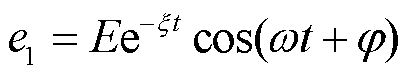 (13)
(13)
式中, 为阻尼系数,
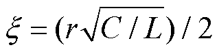 ;
; 为角频率;
为角频率; 为初相位。
为初相位。
振动曲线的包络线公式为
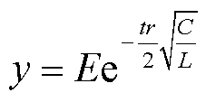 (14)
(14)
根据磁致伸缩波导丝磁化理论可得扭转波信号电压的表达式为
 (15)
(15)
式中, 为波导丝在永磁体处的磁导率;
 为永磁体处的磁致伸缩应变系数;
 为永磁体处沿波导丝轴向的磁场强度。
当y≥e0时,扭转波信号无法被识别,此时永磁体进入测量盲区。令y=e0可得到磁致伸缩位移传感器测量盲区的表达式为
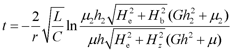 (16)
(16)
采用高纯金属(99.9%)在氩气保护下感应熔炼制备了标称成分为(Fe83Ga17)99.4B0.6、Fe46.5Ni48.5Cr2Ti2.5Al0.5和Fe30Co70的铸铁基合金。分别经过热锻和轧制加工,将铸锭加工成直径为8 mm的线材,然后在加工过程中通过冷拔和多次热处理进一步将直径减小至0.6 mm,拉伸线材经过直流退火后得到磁致伸缩波导丝。利用综合物性测量系统(Physical Property Measurement System, PPMS)测量得到了材料的磁滞回线、磁致伸缩曲线以及应变系数与轴向磁场的关系。
三种波导丝的磁滞回线如图4a所示,它们在低磁场情况下的斜率有明显不同,斜率越大,对弱磁场越敏感。采用标准应变片法测量了三根波导丝的磁致伸缩系数,测量结果如图4b所示。图4c显示了三根波导丝中应变系数h与轴向磁场Hz的关系。通过测量磁致伸缩波导丝试样在轴向磁场和幅值为1 kA/m、频率为1 kHz的正弦交流磁场作用下沿纵向的振动位移,得到磁致伸缩应变系数h。随着轴向磁场的增大,应变系数呈先增大后减小的趋势。
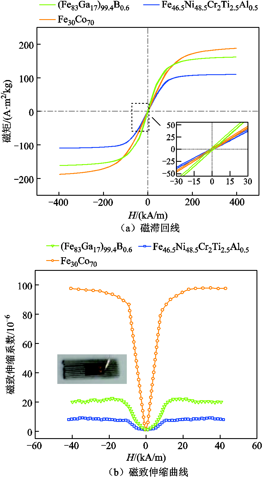
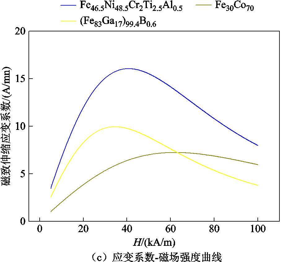
图4 材料参数测量
Fig.4 Measurement of material parameters
用于数值计算的材料参数见表1。密度ρ和剪切模量G取自文献[25-27]的实验数据。磁弹性耦合系数hi由和Hz测量得到。
表1 波导丝相关参数
Tab.1 Related parameters of wire
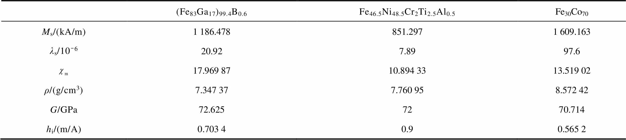
(Fe83Ga17)99.4B0.6Fe46.5Ni48.5Cr2Ti2.5Al0.5Fe30Co70 Ms/(kA/m)1 186.478851.2971 609.163 λs/10-620.927.8997.6 17.969 8710.894 3313.519 02 ρ/(g/cm3)7.347 377.760 958.572 42 G/GPa72.6257270.714 hi/(m/A)0.703 40.90.565 2
本文搭建了提供可调脉冲电流和轴向偏置磁场的测试装置如图5所示,自制了斩波电路,将可调直流源输出的直流电压斩波为窄脉冲电压,匹配波导丝电阻作为驱动脉冲电流,通过调节直流源输出电压调制为合适的脉冲电流幅值。设计两块对向移动的永磁体,其中心位置产生的磁场作为波导丝轴向磁场。永磁体沿厚度方向充磁,且充磁方向同向、并置于可相对移动的可调滑台上。
构建如图5所示的磁致伸缩位移传感器实验平台。可调直流源为AMETEK公司的SorensenXG600-1.4可编程直流电源,斩波电流最高输出150 V的脉冲电压,脉冲宽度15 μs,用以提供脉冲电流形成周向激励磁场。可调永磁体夹具的单向行程为40 mm,夹具上固定Nd2Fe14B永磁体,牌号N38,尺寸为 15 mm×10 mm×5 mm,剩磁Br=1.2 T,矫顽力Hc= 899 kA/m,充磁方向沿厚度方向指向波导丝平行方向,为波导丝提供可变化的轴向磁场。被测波导丝两端用阻尼固定[28],使用恒压弹簧将波导丝拉直,拉力小于1 N。检测线圈套入波导丝,线圈800匝,平均截面积为12.56 mm2,骨架内径为2 mm,漆包线线径为0.06 mm,两端引线不经放大器及滤波电路接入示波器测量输出电压,示波器型号为Tektronix公司的DPO3014数字示波器。

图5 磁致伸缩位移传感器实验平台
Fig.5 Magnetostrictive displacement sensor experimental platform
为验证脉冲响应电压模型的正确性,将p和设置为变量,永磁体到波导丝的垂直距离由文献[9]中得出的最大扭转波输出电压求得,该距离为8.3 mm,(Fe83Ga17)99.4B0.6、Fe46.5Ni48.5Cr2Ti2.5Al0.5和Fe30Co70波导丝在不同p和情况下的测量盲区如图6所示。
理论模型的计算结果与实验结果基本一致,表明式(18)可用于预测测量盲区。两种结果存在一定偏差,这是由于实际情况中会有很多外在因素的影响,扭转波的振动使粒子间的摩擦发生变化以及外界温度的变化等都会影响测量盲区的宽度。
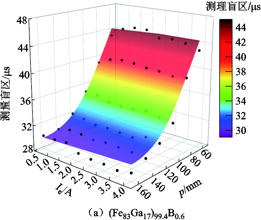
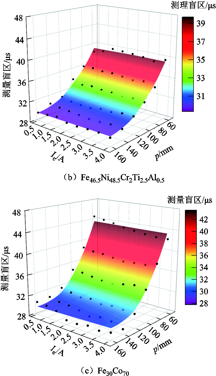
图6 不同p和 情况下测量盲区的测量值(黑点)和理论值(彩色面)
Fig.6 Measured (black dots) and theoretical (colored surfaces) values of the measurement blindness for different p and
因为检测线圈的参数固定,所以测量盲区模型中的RLC数值固定,因此主要分析脉冲电流产生的周向磁场与永磁体产生的轴向磁场对测量盲区的影响。由图6可知,随着脉冲电流的增大,三组不同波导丝传感器的测量盲区基本不变,因此可得测量盲区基本不受脉冲电流产生的周向磁场影响。而三组不同波导丝传感器的测量盲区都随着永磁体到检测线圈的直线距离的减小而增加。这是由于在永磁体靠近检测线圈的过程中,检测线圈处的轴向磁场会逐渐增大,导致波导丝的磁致伸缩应变系数和磁导率发生变化,进而导致测量盲区的变化。
通过测量盲区模型可知,永磁体产生的磁场对于测量盲区有很大影响,采用磁屏蔽装置可以降低外界静磁场对检测线圈的干扰。磁屏蔽装置常用的形状有球形和圆柱形,本文采用的是易于制作的圆柱形磁屏蔽装置。磁屏蔽装置的材料选用高磁导率的坡莫合金[29](牌号:1J85),其相关参数见表2。
表2 坡莫合金(1J85)相关参数
Tab.2 Related parameters of permalloy (1J85)
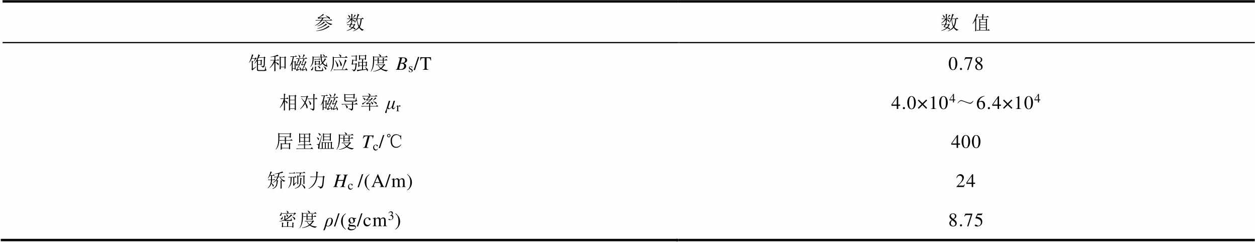
参数数值 饱和磁感应强度Bs/T0.78 相对磁导率μr4.0×104~6.4×10⁴ 居里温度Tc/℃400 矫顽力Hc /(A/m)24 密度ρ/(g/cm3)8.75
大多数情况下,当圆柱形磁屏蔽罩之间存在相当于内壳直径5%~10%的气隙时,其屏蔽量可达到相同厚度的磁屏蔽罩屏蔽量的90%[30],这表明可以在不牺牲性能的情况下使用中间存在气隙的多层磁屏蔽结构。磁屏蔽装置为一端封闭、中心开有圆孔且轴心相同的多层筒状结构,封闭端靠近永磁体,波导丝从圆孔穿过,检测线圈固定于磁屏蔽装置内,其实验平台如图7所示。
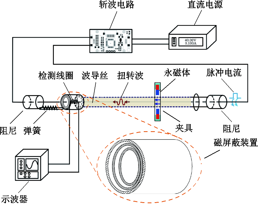
图7 改良后的磁致伸缩位移传感器实验平台
Fig. 7 The improved experimental platform of magnetostrictive displacement sensor
磁屏蔽装置用于屏蔽永磁体对检测线圈产生的磁干扰,属于静磁屏蔽。磁屏蔽系数定义为
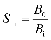 (17)
(17)
式中, 为屏蔽装置外部磁场磁感应强度;
 为屏蔽装置内部磁场磁感应强度。
当磁屏蔽罩为n层时,其横向磁屏蔽系数为[31]
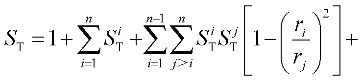
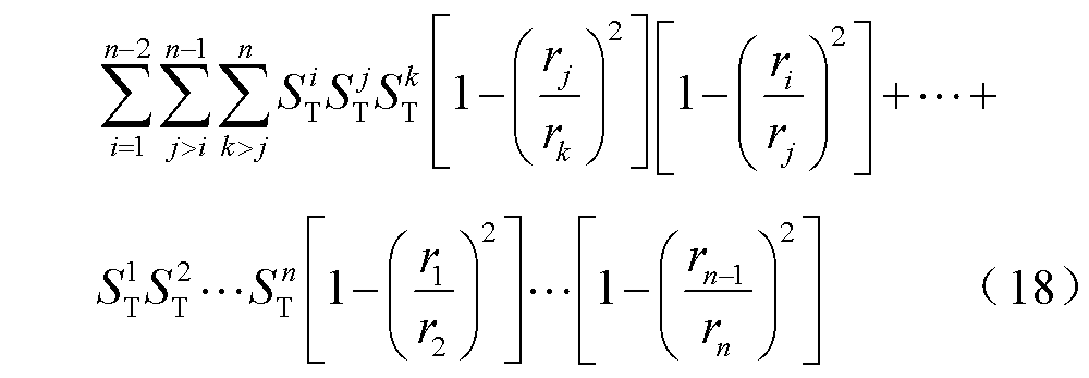
式中,下标i代表第i层磁屏蔽罩; 为第i层磁屏蔽罩半径;
 为第i层屏蔽横向磁屏蔽导数。
当磁屏蔽罩为n层时,其纵向磁屏蔽系数为
式中, 为第i层屏蔽罩纵向磁屏蔽系数;
 为第i层磁屏蔽罩长度。
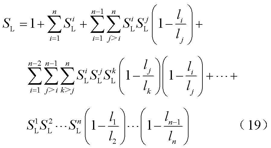
根据“短板效应”,选取横向磁屏蔽系数与纵向磁屏蔽系数中较小的一个作为总体屏蔽系数,即
 (20)
(20)
将第一层磁屏蔽罩的半径r1作为变量,取磁屏蔽罩的间隔为 ,磁屏蔽罩的厚度
 ,磁屏蔽材料的相对磁导率
 ,第一层磁屏蔽罩的体积为
 。第n层磁屏蔽罩的半径为
 ,长度为
,长度为 。图8为不同层数磁屏蔽罩的半径和长度对静磁屏蔽系数S的影响。由图8a可知,随着r1的增加,磁屏蔽系数先增大后减小。随着磁屏蔽罩层数的增加,磁屏蔽系数增大。由图8b可知,随着l1的增加,磁屏蔽系数先增大后减小。随着磁屏蔽罩层数的增加,磁屏蔽系数增大。
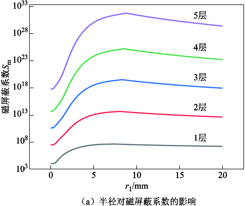
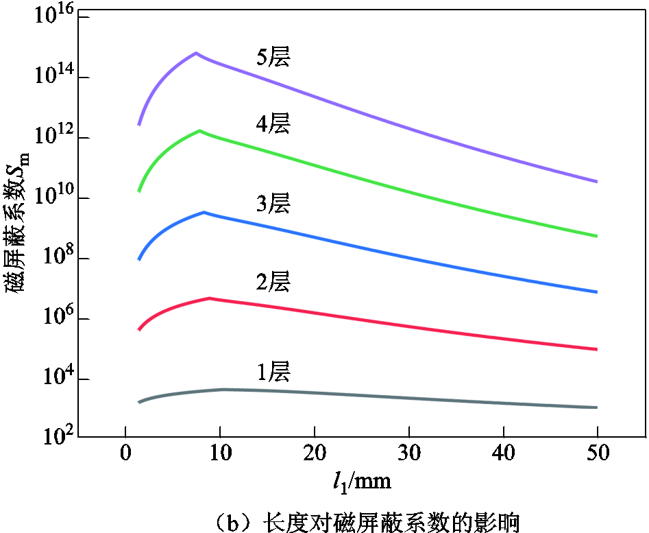
图8 磁屏蔽罩半径和长度对磁屏蔽系数的影响
Fig.8 Effect of radius and length of magnetic shield on magnetic shielding coefficient
因为检测线圈的长度为10 mm,半径为5 mm,所以要限定第一层磁屏蔽罩的长度l1不小于10 mm,半径r1不小于5 mm。结合限定条件,从图8中得出不同层数磁屏蔽装置的最佳尺寸,见表3。
表3 不同层数磁屏蔽装置的相关参数
Tab.3 Parameters related to magnetic shielding devices with different layers
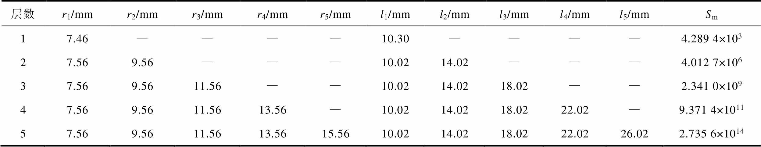
层数r1/mmr2/mmr3/mmr4/mmr5/mml1/mml2/mml3/mml4/mml5/mmSm 17.46————10.30————4.289 4×10³ 27.569.56———10.0214.02———4.012 7×10⁶ 37.569.5611.56——10.0214.0218.02——2.341 0×109 47.569.5611.5613.56—10.0214.0218.0222.02—9.371 4×10¹¹ 57.569.5611.5613.5615.5610.0214.0218.0222.0226.022.735 6×10¹⁴
为测试磁致伸缩位移传感器样机测量盲区变化,搭建优化后的测试实验平台。分别以(Fe83Ga17)99.4B0.6、Fe30Co70和Fe46.5Ni48.5Cr2Ti2.5Al0.5作为波导丝,在检测线圈处增加不同层数的磁屏蔽装置,使用示波器记录传感器输出的脉冲响应电压波形。图9为不同层数磁屏蔽装置情况下,实验测量的三种波导丝传感器脉冲响应电压幅值的变化。脉冲响应电压幅值随着磁屏蔽层数的增加而减小,逐渐接近永磁体距离检测线圈较远时的电压幅值。这表明随着磁屏蔽装置层数的增加,永磁体对检测线圈的影响逐渐减小。
在不同层数磁屏蔽装置的情况下,实验测量了三种波导丝传感器测量盲区的变化,如图10所示。实验结果表明:当磁屏蔽装置在3层以内时,测量盲区随着磁屏蔽装置层数的增加而快速减小。当磁屏蔽装置大于3层时,测量盲区随层数的增加而缓慢减小。因此,在考虑成本的前提下,磁屏蔽装置为3层时屏蔽效率较高,此时(Fe83Ga17)99.4B0.6波导丝传感器测量盲区持续时间由30.05 μs缩短为18.45 μs,宽度缩短了38.6%;Fe30Co70波导丝传感器测量盲区持续时间由29.55 μs缩短为18.85 μs,宽度缩短了36.2%;Fe46.5Ni48.5Cr2Ti2.5Al0.5波导丝传感器测量盲区持续时间由31.15 μs缩短为19.15 μs,宽度缩短了38.5%。
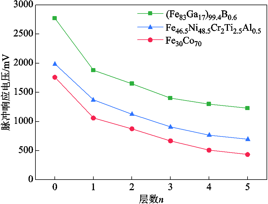
图9 不同层数磁屏蔽装置情况下的脉冲响应电压幅值
Fig.9 Impulse response voltage amplitude for magnetic shielding devices with different layers

图10 不同层数磁屏蔽装置情况下的测量盲区
Fig.10 Measurement blindness in case of different layers of magnetic shielding devices
本文为拓宽磁致伸缩位移传感器在测量空间受限环境下的应用范围,研究了磁致伸缩位移传感器的测量盲区,通过减小静磁场对于检测线圈的影响,缩短了传感器检测线圈处的测量盲区。基于魏德曼效应、磁弹性耦合效应和维拉里效应建立了磁致伸缩位移传感器的测量盲区模型,计算了磁致伸缩位移传感器的测量盲区。计算表明:随着永磁体到检测线圈直线距离的减小,检测线圈处的轴向磁场强度会逐渐增大,导致传感器测量盲区的持续时间增加。
通过研究永磁体产生的轴向偏置磁场与测量盲区之间的关系,验证了增加磁屏蔽装置来缩短测量盲区的有效性。确定了最佳磁屏蔽装置参数,制作了优化后的磁致伸缩位移传感器样机。通过实验证明了样机在靠近检测线圈处的测量盲区有效减小,可以应用于测量空间有限情况下的高精度位移测量。该研究可为磁致伸缩位移传感器的优化设计提供理论依据与指导。
参考文献
[1] Hu Guang, Zhang Huang, Liu Qianfeng. Review on sensors to measure control rod position for nuclear reactor[J]. Annals of Nuclear Energy, 2020, 144: 107485.
[2] Kim Y, Choi H Y, Lee Y C. Design and preliminary evaluation of high-temperature position sensors for aerospace applications[J]. IEEE Sensors Journal, 2014, 14(11): 4018-4025.
[3] Karafi M R, Hojjat Y, Sassani F, et al. A novel magnetostrictive torsional resonant transducer[J]. Sensors and Actuators A: Physical, 2013, 195: 71-78.
[4] 周翟和, 汪丽群, 沈超, 等. 基于CPLD的磁致伸缩高精度时间测量系统设计[J]. 仪器仪表学报, 2014, 35(1): 103-108.
Zhou Zhaihe, Wang Liqun, Shen Chao, et al. Design of magnetostrictive high-precision time measurement system based on CPLD[J]. Chinese Journal of Scientific Instrument, 2014, 35(1): 103-108.
[5] Hristoforou E, Hauser H, Ktena A. Modeling of magnetostriction in amorphous delay lines[J]. Journal of Applied Physics, 2003, 93(10): 8633.
[6] Hristoforou E. New position sensor based on the magnetostrictive delay line principle[J]. Sensor Letters, 2009, 7(3): 303-309.
[7] Zhou Xinzhi, Yu Chao, Tang Zhenyu, et al. Wiedemann effect in Fe83Ga17 alloys for magnetostrictive sensors[J]. IEEE Sensors Journal, 2014, 14(1): 249-257.
[8] Deng Chao, Kang Yihua, Li Erlong, et al. A new model of the signal generation mechanism on magnetostrictive position sensor[J]. Measurement, 2014, 47: 591-597.
[9] 黄文美, 夏志玉, 郭萍萍, 等. 变温条件下TbDyFe合金高频磁特性和损耗特性分析[J]. 电工技术学报, 2022, 37(1): 133-140.
Huang Wenmei, Xia Zhiyu, Guo Pingping, et al. Analysis of high frequency magnetic properties and loss characteristics of TbDyFe alloy under variable temperature[J]. Transactions of China Electrotechnical Society, 2022, 37(1): 133-140.
[10] 黄文美, 陶铮, 郭萍萍, 等. 变压应力条件下铁镓合金棒材高频磁特性测试与模型构建[J]. 电工技术学报, 2023, 38(14): 3769-3778.
Huang Wenmei, Tao Zheng, Guo Pingping, et al. Analysis and modeling of high frequency magnetic properties of rod gallium iron alloy under variable compressive stress[J]. Transactions of China Electrotechnical Society, 2023, 38(14): 3769-3778.
[11] 黄文美, 陶铮, 郭萍萍, 等. 棒状铁镓合金磁特性测试装置的设计与实验[J]. 电工技术学报, 2023, 38(4): 841-851.
Huang Wenmei, Tao Zheng, Guo Pingping, et al. Design and experiment of high frequency magnetic properties testing device for rod iron-gallium alloy[J]. Transactions of China Electrotechnical Society, 2023, 38(4): 841-851.
[12] 黄文美, 郭萍萍, 郭万里, 等. 直流偏置对磁致伸缩材料高频动态损耗及磁特性的影响分析[J]. 电工技术学报, 2022, 37(22): 5765-5775.
Huang Wenmei, Guo Pingping, Guo Wanli, et al. Impact analysis of DC bias on high-frequency dynamic loss and magnetic characteristics for magnetostrictive materials[J]. Transactions of China Electrotechnical Society, 2022, 37(22): 5765-5775.
[13] 张露予, 王博文, 翁玲, 等. 螺旋磁场作用下磁致伸缩位移传感器的输出电压模型及实验[J]. 电工技术学报, 2015, 30(12): 21-26.
Zhang Luyu, Wang Bowen, Weng Ling, et al. The output voltage model of magnetostrictive displacement sensor in helical magnetic fields and its experimental study[J]. Transactions of China Electrotechnical Society, 2015, 30(12): 21-26.
[14] Zhang Luyu, Wang Bowen, Yin Xiaowen, et al. The output characteristics of galfenol magnetostrictive displacement sensor under the helical magnetic field and stress[J]. IEEE Transactions on Magnetics, 2016, 52(7): 4001104.
[15] 王博文, 张露予, 王鹏, 等. 磁致伸缩位移传感器检测信号分析[J]. 光学精密工程, 2016, 24(2): 358-364.
Wang Bowen, Zhang Luyu, Wang Peng, et al. Analysis of detection signal for magnetostrictive displacement sensor[J]. Optics and Precision Engineering, 2016, 24(2): 358-364.
[16] 谢新良, 王博文, 周露露, 等. 磁致伸缩位移传感器波导丝扭转超声波衰减特性研究[J]. 电工技术学报, 2018, 33(3): 689-696.
Xie Xinliang, Wang Bowen, Zhou Lulu, et al. Research on torsional ultrasonic attenuation characteristics of the magnetostrictive displacement sensor waveguide[J]. Transactions of China Electrotechnical Society, 2018, 33(3): 689-696.
[17] 李媛媛, 王博文, 黄文美, 等. 扭转力作用下Fe-Ga磁致伸缩位移传感器的输出特性[J]. 电工技术学报, 2019, 34(21): 4409-4418.
Li Yuanyuan, Wang Bowen, Huang Wenmei, et al. Output characteristics of Fe-Ga magnetostrictive displacement sensor under torsional stress[J]. Transactions of China Electrotechnical Society, 2019, 34(21): 4409-4418.
[18] 李媛媛, 王博文, 黄文美, 等. 考虑应力波衰减特性的磁致伸缩位移传感器的输出特性与实验[J]. 仪器仪表学报, 2018, 39(7): 34-41.
Li Yuanyuan, Wang Bowen, Huang Wenmei, et al. Output characteristics and experiments of magnetostrictive displacement sensor considering the attenuation characteristic of stress wave[J]. Chinese Journal of Scientific Instrument, 2018, 39(7): 34-41.
[19] Wang Bowen, Li Yuanyuan, Xie Xinliang, et al. The output voltage model and experiment of magnetostrictive displacement sensor based on Weidemann effect[J]. AIP Advances, 2018, 8(5): 056611.
[20] Zheng Xiaojing, Liu X E. A nonlinear constitutive model for Terfenol-D rods[J]. Journal of Applied Physics, 2005, 97(5): 053901.
[21] Dapino M J, Smith R C, Flatau A B. Structural magnetic strain model for magnetostrictive transducers [J]. IEEE Transactions on Magnetics, 2000, 36(3): 545-556.
[22] Lee E W. Magnetostriction and magnetomechanical effects[J]. Reports on Progress in Physics, 1955, 18(1): 184-229.
[23] 孙英, 武泽航, 张耀松, 等. 永磁体对磁致伸缩位移传感器波导丝扭转应变的影响分析[J]. 仪器仪表学报, 2021, 42(4): 10-23.
Sun Ying, Wu Zehang, Zhang Yaosong, et al. Analysis of the influence of permanent magnet on the torsional strain of waveguide wire of the magnetostrictive displacement sensor[J]. Chinese Journal of Scientific Instrument, 2021, 42(4): 10-23.
[24] 陈铮. Fe-Ga材料磁致伸缩位移传感器输出特性影响因素研究[D]. 天津: 河北工业大学, 2020.
Chen Zheng. Study on influencing factors of output characteristics of Fe-Ga magnetostrictive displacementsensor[D]. Tianjin: Hebei University of Technology, 2020.
[25] Li Jiheng, Li Mingming, Mu Xing, et al. Temperature and magnetic field dependencies of the Young’s modulus in magnetostrictive Fe-Ga alloys[J]. Journal of Applied Physics, 2018, 123(7): 075102.
[26] Li Jiheng, Li Mingming, Mu Xing. Magnetostrictive Fe–Ga wires for application in the high-temperature waveguide device[J]. Materials Transactions, 2018, 59(4): 679-684.
[27] Belousov O K, Palii N A. Concentration and temperature dependences of the elastic properties of quenched Fe-Co and FeCo-2V alloys[J]. Russian Metallurgy (Metally), 2009, 2009(1): 41-49.
[28] 吴益飞, 肖宇, 杨飞, 等. 基于磁耦合电流转移的阻尼式直流开断技术[J]. 电力系统自动化, 2022, 46(13): 168-176.
Wu Yifei, Xiao Yu, Yang Fei, et al. Damping DC breaking technology based on magnetic induction current commutation[J]. Automation of Electric Power Systems, 2022, 46(13): 168-176.
[29] 李奎, 李常宇, 牛峰, 等. 电磁式漏电断路器的空间磁场抗扰分析及屏蔽结构设计[J]. 电工技术学报, 2022, 37(9): 2161-2169.
Li Kui, Li Changyu, Niu Feng, et al. Anti-magnetic field interference analysis and shielding structure design of electromagnetic residual current circuit breaker[J]. Transactions of China Electrotechnical Society, 2022, 37(9): 2161-2169.
[30] Paperno E, Peliwal S, Romalis M V, et al. Optimum shell separation for closed axial cylindrical magnetic shields[J]. Journal of Applied Physics, 2005, 97(10): 10Q104.
[31] 李攀, 刘元正, 王继良. 核磁共振陀螺多层磁屏蔽系统优化设计[J]. 中国惯性技术学报, 2016, 24(3): 383-389.
Li Pan, Liu Yuanzheng, Wang Jiliang. Optimization design of multilayer magnetic shield for nuclear magnetic resonance gyroscopes[J]. Journal of Chinese Inertial Technology, 2016, 24(3): 383-389.
Failure Mechanism of Measurement Blindness in Magnetostrictive Displacement Sensors and Optimization of Magnetic Shielding
Abstract Magnetostrictive displacement sensors use the Weidmann effect to achieve displacement measurement, with high accuracy, non-contact, high reliability and adaptable to harsh environments, etc., and are widely used in a variety of fields. Due to the existence of measurement blind zones near the detection coil, the effective measurement range of magnetostrictive displacement sensors is difficult to meet the application requirements in the field of hydraulic cylinders, robotic arms and other areas where the installation space is limited. This problem limits the development of precision measurement and precision displacement control.
In order to reduce the measurement blind zone of magnetostrictive displacement sensors in the vicinity of the detection coil and to widen the application range of magnetostrictive displacement sensors in environments where measurement space is limited. Based on the Weidmann effect, magneto-elastic coupling effect and Villari effect, this paper theoretically investigates the relationship between the measurement blind zone of magnetostrictive displacement sensors and the synthetic magnetic field, establishes a model of the measurement blind zone of magnetostrictive displacement sensors under the action of the synthetic magnetic field, and analyses the failure mechanism of magnetostrictive displacement sensors in the measurement blind zone. The theoretical model shows that the measurement blind zone is affected by the axial magnetic field generated by the permanent magnet, and the measurement blind zone increases with the axial magnetic field. An experimental platform was built to provide adjustable pulse current and axial magnetic field, and experiments were conducted using (Fe83Ga17)99.4B0.6, Fe46.5Ni48.5Cr2Ti2.5Al0.5 and Fe30Co70 waveguide wires with a diameter of 0.6 mm, which verified the accuracy of the measurement blind zone model, and a solution was developed to reduce the measurement blind zone by adding a cylindrical multilayer magnetic shielding device. It is concluded that the measurement blind zone can be reduced by adding cylindrical multi-layer magnetic shielding device. The material of the magnetic shielding device is the high permeability permalloy, and the optimal parameters of the static magnetic shielding device are determined by calculating the magnetic shielding coefficient, and the change of the measurement blind zone in the case of different layers of the magnetic shielding device are measured experimentally. The experimental results show that the shielding efficiency is higher when the static magnetic shielding device is 3 layers, at which time the length of the first layer of magnetic shielding is 10.02 mm and the radius is 7.56 mm; the length of the second layer of magnetic shielding is 14.02 mm and the radius is 9.56 mm; the length of the third layer of magnetic shielding is 18.02 mm and the radius is 11.56 mm.A prototype of the improved sensor is fabricated and the prototype's measurement blind area was analysed and tested. The results show that the measurement blind zone of the optimized (Fe83Ga17)99.4B0.6 waveguide wire sensor measurement blind zone is shortened from 30.05 μs to 18.45 μs, and the width is shortened by 38.6%; that of the Fe46.5Ni48.5Cr2Ti2.5Al0.5 waveguide wire sensor measurement blind zone is shortened from 31.15 μs to 19.15 μs, and the width is shortened by 38.5%; that of the Fe30Co70 waveguide wire sensor measurement blind zone is shortened from 29.55 μs to 18.85 μs, and the width is shortened by 36.2%.
The experimental results show that the blind zone of the improved magnetostrictive displacement sensors near the detection coil is effectively reduced, and they can be applied to high-precision displacement measurements in the case of limited measurement space. This study can provide theoretical basis and guidance for the optimal design of magnetostrictive displacement sensors.
keywords:Magnetostriction, displacement sensor, measurement blindness model, static magnetic field shielding
中图分类号:TP212; TM936
DOI: 10.19595/j.cnki.1000-6753.tces.231238
国家自然科学基金(51801053, 52077052)、河北省自然科学基金(E2022202067)和中央引导地方科技发展资金项目(226Z1704G)资助。
收稿日期 2023-07-28
改稿日期 2023-12-07
边铁錾 男,1995年生,硕士研究生,研究方向为新型磁性材料与器件。
E-mail:tz98595@163.com
李明明 男,1986年生,副教授,博士生导师,研究方向为新型磁性材料与器件。
E-mail:Limm@hebut.edu.cn(通信作者)
(编辑 郭丽军)