 和
和 分别为一次侧和二次侧主线圈自感,
 和
和 为一、二次侧补偿电感,
 分别为一、二次侧补偿电容,
 为系统的负载电阻,
 分别为一、二次侧电感内阻,模型考虑了电感线圈内阻对传输效率的影响。
摘要 为实现植入式心脏起搏器无线电能传输系统的体积小型化以及改善系统的传输性能,该文提出一种基于LCC-LCC磁集成印刷螺旋线圈(PSC)的心脏起搏器无线电能传输系统。首先,建立线圈模型,研究在填充比率固定条件下PSC的匝宽和匝间距对传输效率的影响,确定最佳的线圈参数;其次,建立非集成式和集成式耦合机构的仿真模型,计算不同偏移情况下两种耦合机构的磁场分布情况;最后,搭建非集成式与集成式无线电能传输系统,验证集成结构在传输性能方面的优势。结果表明:在12 mm的传输距离下,传输效率由62.3%提升至68.1%,输出功率提升了0.39 W。此外,通过模拟计算无线充电过程中电场强度和比吸收率(SAR)值在人体内的分布情况,对系统进行安全评估。集成式PCS的提出有助于推进心脏起搏器无线电能传输系统的产品化进程。
关键词:无线电能传输 心脏起搏器 磁集成 印刷螺旋线圈
目前心脏起搏器大多采用锂电池供电,由于锂电池容量有限,患者不得不定期进行手术干预更换,这会导致极高的手术风险[1-4]。近年来,磁耦合谐振式无线电能传输(Magnetically Coupled Resonant Wireless Power Transmission, MCR-WPT)技术[5]由于其相较于有线传能具有安全、方便等优势,在生物医学植入领域拥有广阔的应用前景[6-10]。然而,若要将MCR-WPT技术应用于临床,传输效率以及安全性是必须优先考虑的重要问题。在推动这项技术的发展和应用过程中,磁耦合机构、拓扑结构以及电磁安全等方面已成为国内外许多专家学者研究的重点[11-13]。
在MCR-WPT系统中,补偿拓扑对于实现电能传输具有重要意义。早期大多使用四种基本补偿拓扑[14]:发射端串联-接收端串联(SS)、发射端串联-接收端并联(SP)、发射端并联-接收端串联(PS)和发射端并联-接收端并联(PP)。为了得到更好的输出特性,在基本补偿网络的基础上,双端LCL拓扑(LCL-LCL)、LCL-S拓扑(LCC-S)以及双端LCC拓扑(LCC-LCC)等复合补偿拓扑[15-19]相继被提出。复合补偿拓扑的使用可以使整个系统在偏移条件下具有较高的鲁棒性,同时满足恒压或恒流的输出要求。然而,由于复合补偿拓扑的补偿点通常以独立电感的形式存在,这会导致整个系统的体积增大。因此,传统的复合补偿拓扑在植入式设备中并不适用。为了解决这个问题,目前已经有研究将外部补偿电感与主线圈集成起来,以形成更紧凑的线圈结构。
文献[20]基于LCC-LCC补偿拓扑提出了一种将单极性补偿线圈集成到DD主线圈中的方法,实现了系统尺寸的压缩和一定的抗偏移特性。文献[21]将LCC-LCC型补偿电感以双D型线圈的形式叠放在以单极性线圈方式缠绕的主线圈上面,在X和Y方向上偏移150 mm处,其所提出的MCR-WPT系统可保留至少56.8%和82.6%的对准功率。文献[22]提出了一种三极板集成双面LCC补偿网络及其整定方法,采用此集成结构的MCR-WPT系统在节省约29%的体积的情况下提高了对横向和旋转位移的容忍度,但是集成后的传输效率相较于非集成结构略有下降。综上可以看出,目前大部分将补偿电感与主线圈集成的尝试中,往往是将补偿线圈解耦,或者补偿线圈之间的耦合相对较小,忽略不计,并没有考虑与补偿电感的耦合。
此外磁耦合机构作为MCR-WPT系统的重要组成部分,目前常用的线圈主要有利兹线圈和印刷螺旋线圈(Printed Spiral Coil, PSC)两种,相比于较为笨重的利兹线圈,PSC更加轻巧,可以减轻对植入位置的压力和负担,这更适合于工作在植入式设备中。此外PSC具有制作成本低以及加工精度高的优点,有助于标准化生产。同时由于PSC独特的平面结构,使其在紧凑式线圈设计时成为更优的选择[23]。
本文为减小植入式心脏起搏器无线电能传输系统的体积、提高传输效率以及抗偏移能力,提出了一种基于LCC-LCC磁集成PSC的心脏起搏器无线电能传输系统。通过建立线圈模型分析了PSC的匝宽和匝间距对传输效率的影响,搭建仿真与实验系统,对比非集成式和集成式结构的传输性能,此外构建人体上半身三维模型,通过计算体内的电场强度与比吸收率(Specific Absorption Ratio, SAR)值对植入式无线电能传输系统的安全性进行评估。
本文所采用的基于LCC-LCC补偿拓扑的集成式耦合机构等效电路如图1所示。图中和分别为一次侧和二次侧主线圈自感,和为一、二次侧补偿电感,分别为一、二次侧补偿电容,为系统的负载电阻,分别为一、二次侧电感内阻,模型考虑了电感线圈内阻对传输效率的影响。
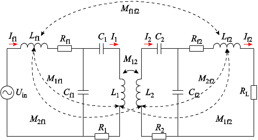
图1 LCC-LCC补偿拓扑的集成式耦合机构等效电路
Fig.1 Equivalent circuit of integrated coupling mechanism of LCC-LCC compensation topology
本文提出的LCC-LCC集成式耦合机构中存在多个耦合关系,分别为一次侧主线圈与二次侧主线圈间的互感 ,一次侧主线圈与一次侧谐振线圈之间的互感
 ,一次侧主线圈与二次侧谐振线圈
 之间的互感
之间的互感 ,二次侧主线圈与一次侧谐振线圈之间的互感
 ,二次侧主线圈与二次侧谐振线圈之间的互感
 ,一次侧与二次侧谐振线圈之间的互感
 。
。
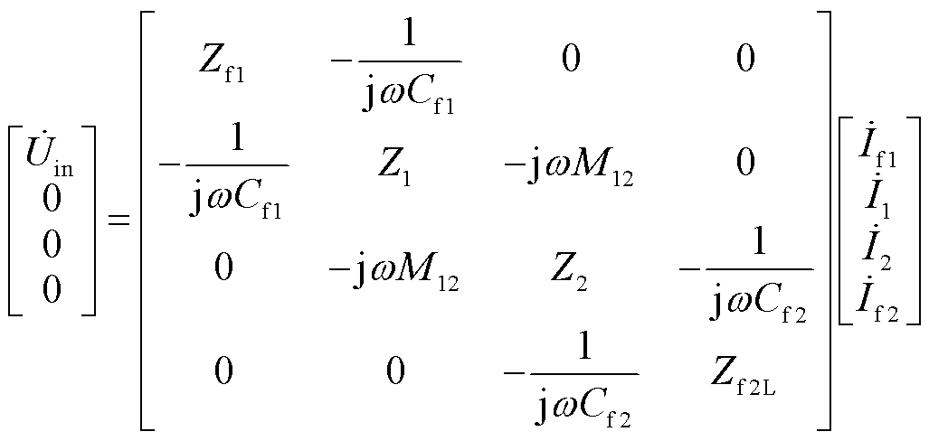
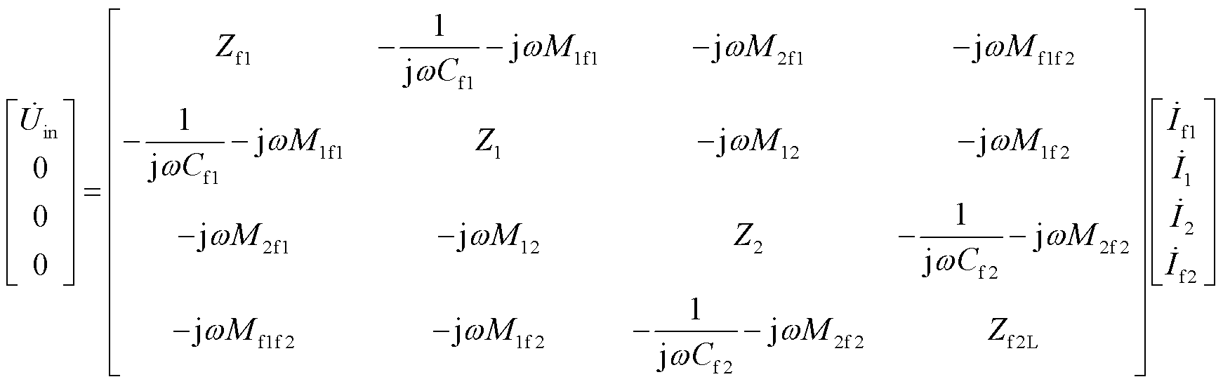
而非集成式耦合机构中耦合关系仅有一个,即一次侧主线圈与二次侧主线圈之间的互感。对于LCC-LCC补偿拓扑非集成式耦合机构的无线电能传输系统,根据基尔霍夫定律将等效电路中的KVL方程用矩阵形式表示为
 (1)
(1)
式中, 为系统输入电压;
 为系统输入电流;
 为流经一次侧主线圈的电流;
 为流经二次侧主线圈的电流;
 为流经负载的电流;
 为系统角频率;
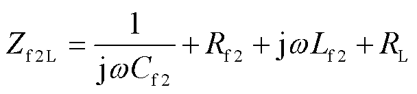
 为各段线路阻抗,其表达式分别为
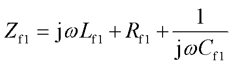 (2)
(2)
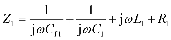 (3)
(3)
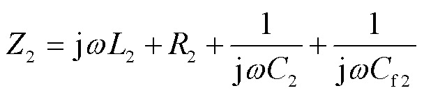 (4)
(4)
 (5)
(5)
当LCC-LCC补偿系统发生谐振时,电路中的阻抗均为纯阻性。系统的谐振条件为
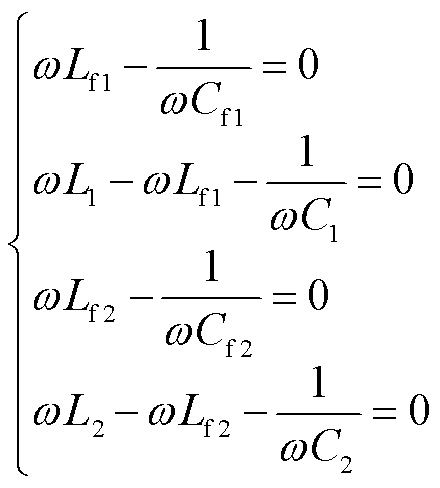 (6)
(6)
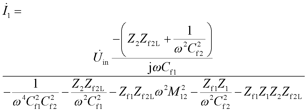
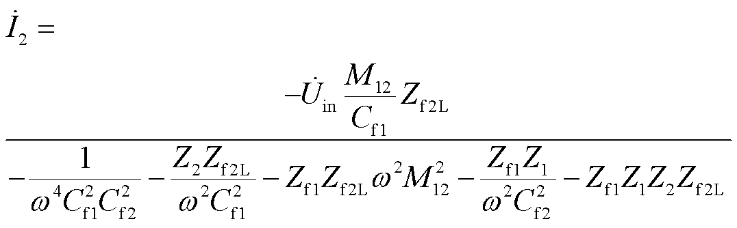
由式(1)~式(6)推导出非集成式耦合机构两侧的电流为
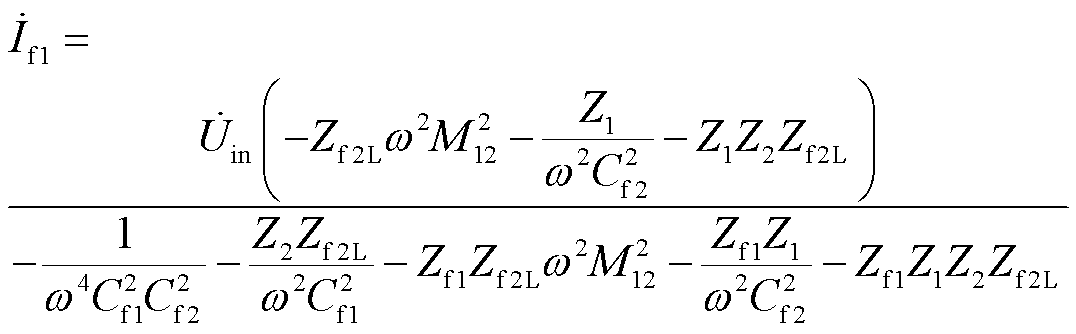 (7)
(7)
 (8)
(8)
 (9)
(9)
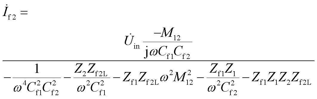 (10)
(10)
根据负载电流的表达式(10)可以得出,当传能系统的输入电压恒定时,流经负载的电流也将保持不变,从而实现电流的恒定。
对于LCC-LCC补偿拓扑集成式耦合机构,其等效电路方程可表示为
 (11)
(11)
为方便计算,将式(11)改写为
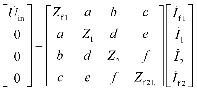 (12)
(12)
其中,a、b、c、d、e、f分别表示为
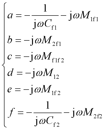 (13)
(13)
对式(12)、式(13)推导计算,集成式耦合机构的输入电流以及流经负载电流的表达式分别为
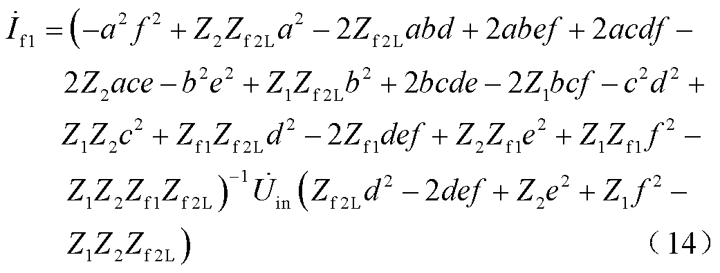
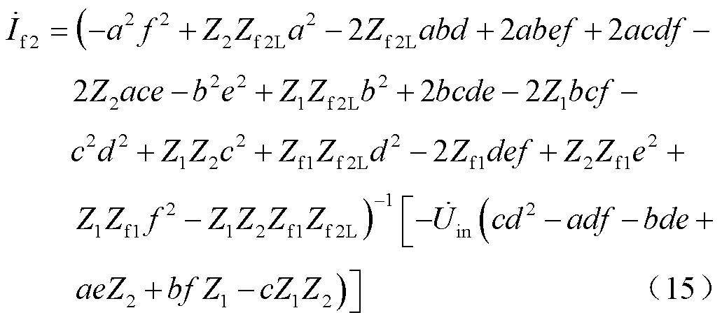
通过输入电流 、流经负载电流
 、输入电压
、输入电压 以及负载电阻计算出输入输出功率
 、
、 ,由此确定系统的传输效率
 。
。
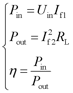 (16)
(16)
LCC-LCC补偿拓扑的集成式PSC结构如图2所示。外侧为主线圈,内侧为补偿线圈,二次线圈与一次线圈结构保持一致。补偿电感线圈以同心圆的形式嵌套到主线圈中,从增强共享磁通的角度出发,集成后的补偿电感线圈与主线圈共享结构中心磁通,补偿电感以线圈形式参与能量传输。PSC参数如图3所示。
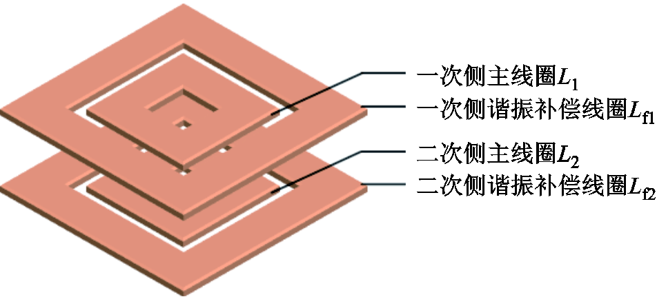
图2 集成式磁耦合机构
Fig.2 Integrated magnetic coupling mechanism
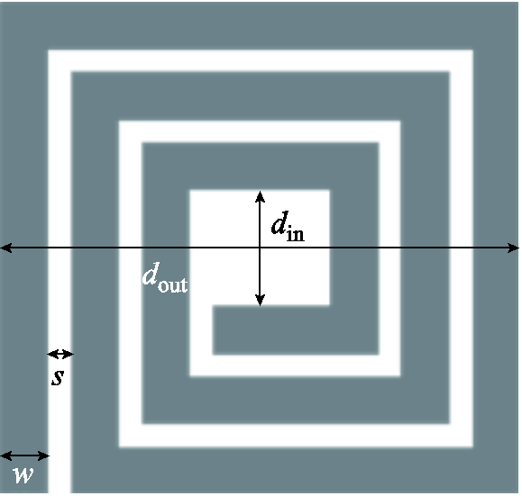
图3 PSC参数
Fig.3 PSC parameters
本文所研究的是应用于植入式心脏起搏器的MCR-WPT系统,根据起搏器50 mm×50 mm×16 mm的外壳几何尺寸,设定主线圈外径 =38 mm,考虑到线圈内侧的涡流效应和邻近效应会导致线圈出现较高的绕组电阻,且补偿电感线圈需要以同心圆的方式嵌套到主线圈内侧,因此设定主线圈内径
 =24 mm。设定线圈之间的耦合距离为12 mm,系统工作频率为6.78 MHz。
在填充比率 固定的情况下,为获得系统最大传输效率,需要对PSC的几何参数进行优化,表1列出了线圈尺寸、耦合距离、制造技术、载波频率方面的设计约束,通过扫描限制参数来确定主线圈的最优结构。
表1 系统约束条件
Tab.1 System constraints
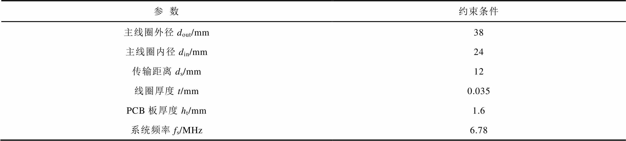
参数约束条件 主线圈外径dout/mm38 主线圈内径din/mm24 传输距离ds/mm12 线圈厚度t/mm0.035 PCB板厚度ht/mm1.6 系统频率fs/MHz6.78
主线圈外径为38 mm,内径为24 mm,因此线圈填充比率为0.23。线圈的结构通常由匝数 、匝宽
、匝宽 和匝间距
和匝间距 三个变量构成。由于线圈填充比率已经确定,因此匝数可通过匝宽和匝间距确定。
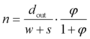 (17)
(17)
传输距离为12 mm,通过对匝宽(0.2~2 mm,步长为0.2 mm)与匝间距(0.2~0.5 mm,步长为0.1 mm)进行参数化扫描来优化PSC结构,采用Ansys Maxwell与Matlab的联合仿真分析,确定 情况下PSC的最佳匝宽和匝间距,优化流程如图4所示。图5显示了在填充比率固定情况下PSC的匝宽、匝间距与传输效率之间的关系。
图4 线圈优化流程
Fig.4 Coil optimization flow chart
图5 线圈匝间距与匝宽对系统传输效率的影响
Fig.5 The influence of coil turn spacing and turn width on the transmission efficiency of the system
从图5中可看出,当线圈的匝间距为0.2 mm、匝宽为1 mm时,线圈可以达到最佳传输效率,由此确定主线圈的结构,具体参数见表2。此外,可以发现,在保持线圈填充比率不变的情况下,增加匝宽可以降低线圈内阻,从而提高系统的传输效率。当匝宽达到最佳值时,线圈自感与阻抗对系统的影响达到平衡,传输效率最高。随着匝宽的继续增加,线圈匝数减少,同时线圈自感与互感也将减小,导致系统传输效率下降。
表2 主线圈结构参数
Tab.2 Main coil structural parameters
参数数值 外径dout/mm38 内径din/mm24 匝宽w/mm1 匝间距s/mm0.2 匝数n6
对于系统采用的LCC-LCC补偿拓扑,当主线圈结构和谐振频率 固定时,仅根据谐振公式无法确定具体的补偿参数。为了确定补偿参数,定义了电感比(补偿电感/主线圈电感),不同的电感比对应不同的补偿参数,并且会影响系统的传输性能。
在6.78 MHz的频率下,利用Matlab软件搭建LCC-LCC补偿拓扑电路,对电感比(0.01~0.99,步长为0.01)进行参数化扫描。图6展示了电感比对系统传输效率的影响。从图中可以看出,在电感比为0.29时系统达到最大传输效率,此时补偿线圈的自感为0.58 μH,通过Ansys软件仿真得出其结构参数见表3。
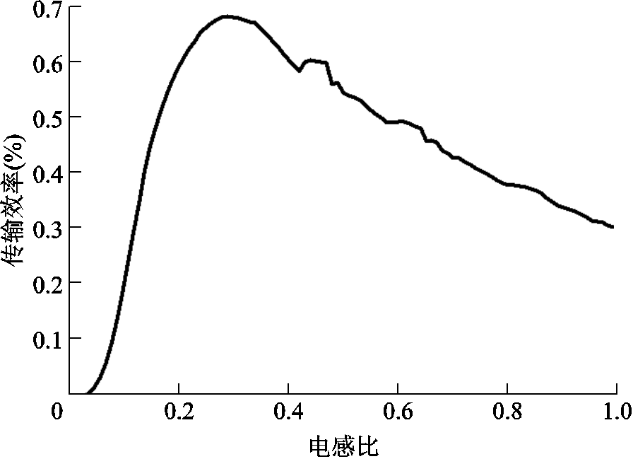
图6 电感比对系统传输效率的影响
Fig.6 The influence of inductance ratio on the transmission efficiency of the system
表3 补偿线圈结构参数
Tab.3 Compensation coil structural parameters
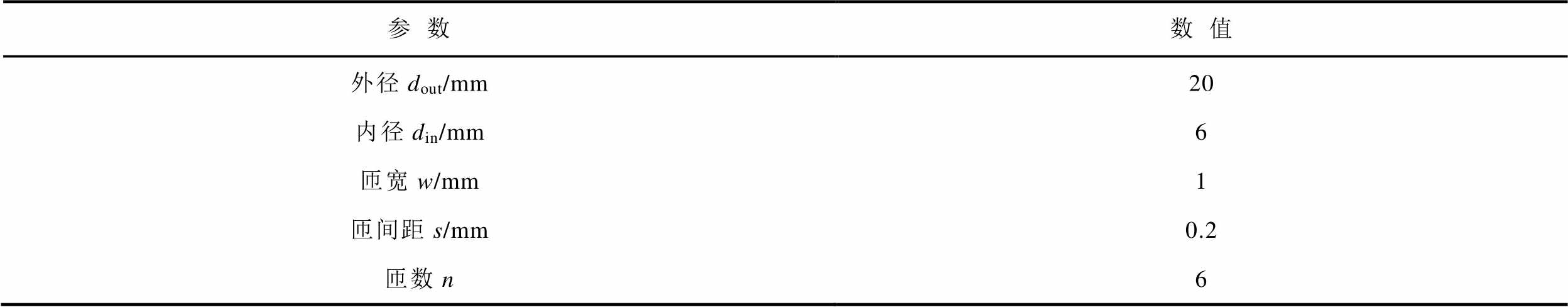
参数数值 外径dout/mm20 内径din/mm6 匝宽w/mm1 匝间距s/mm0.2 匝数n6
为了比较所提出的传统非集成式结构与集成式结构在能量传输方面的差异,建立了非集成式与集成式耦合机构的仿真模型。分别研究了两种耦合机构在发射端与接收端横向偏移以及角度偏移情况下的磁场分布情况。在仿真模型中,工作频率为6.78 MHz,输入激励源相同,发射端和接收端传输距离均为12 mm。在线圈正对无偏移时磁场分布仿真结果如图7所示,从图7可以看出,集成式磁耦合机构的磁场强度要高于非集成式磁耦合机构。
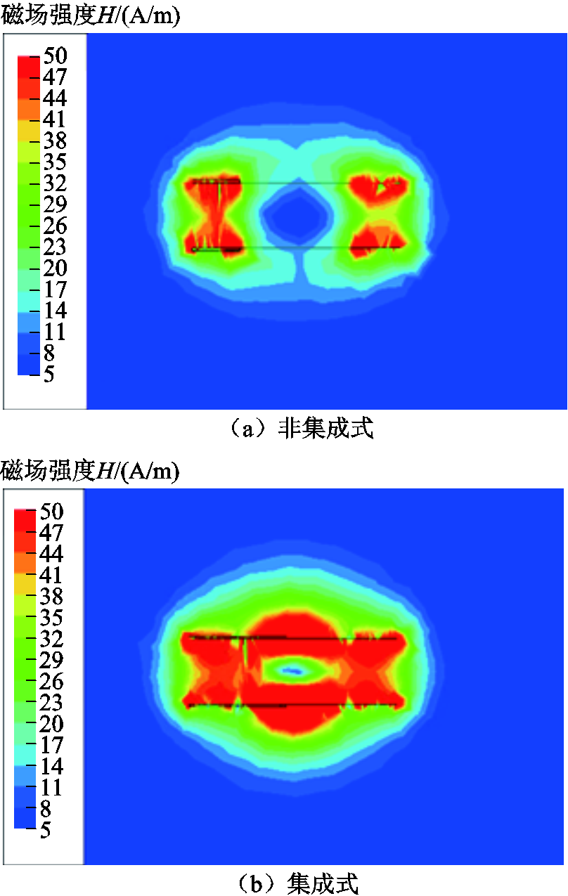
图7 磁耦合机构在正对条件下的磁场强度分布
Fig.7 The magnetic field intensity distribution of the magnetic coupling mechanism under the right condition
图8展示了非集成式与集成式磁耦合机构的接收端分别横向偏移10 mm和20 mm时的仿真结果。在横向偏移状态下,非集成式结构和集成式结构的磁场强度相比于正对状态均有所下降,但是集成式结构的磁场强度依然要高于非集成式结构,且随着偏移距离的增加,集成式结构的磁场强度衰减程度小于非集成式结构。
图9展示了在正对情况下,发射端与接收端不同角度错位下的磁场强度分布。从图9中可以看出,当线圈之间的最小传输距离不变的情况下,随着两个耦合线圈的角度逐渐增大,非集成式结构和集成式结构的磁场强度不断降低,在偏移角度为30°时,集成式结构的磁场强度明显高于非集成式结构,但是当偏移角度进一步扩大时,补偿线圈对能量传输的作用逐渐减弱。
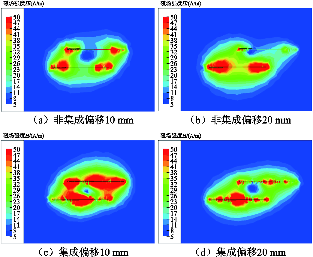
图8 磁耦合机构在不同横向偏移下的磁场强度分布
Fig.8 The magnetic field intensity distribution of the magnetic coupling mechanism under different lateral offsets

图9 磁耦合机构在不同角度偏移下的磁场强度分布
Fig.9 The magnetic field intensity distribution of the magnetic coupling mechanism under different angle offsets
本文搭建了植入式心脏起搏器无线充电实验系统,如图10所示。植入式心脏起搏器的无线充电模型主要包括以下五部分:函数信号发生器、功率放大器、传输线圈与补偿电路以及负载部分。为了模拟现实环境,本文选取猪肉作为实验生物组织代替人体组织,利用2 mm厚的猪皮、3 mm厚的脂肪以及7 mm厚的瘦肉对传输空间进行填充。无线充电系统的基本参数见表4。

图10 实验系统
Fig.10 Experimental system
表4 系统中各元件的基本参数
Tab.4 Basic parameters of each component in the system
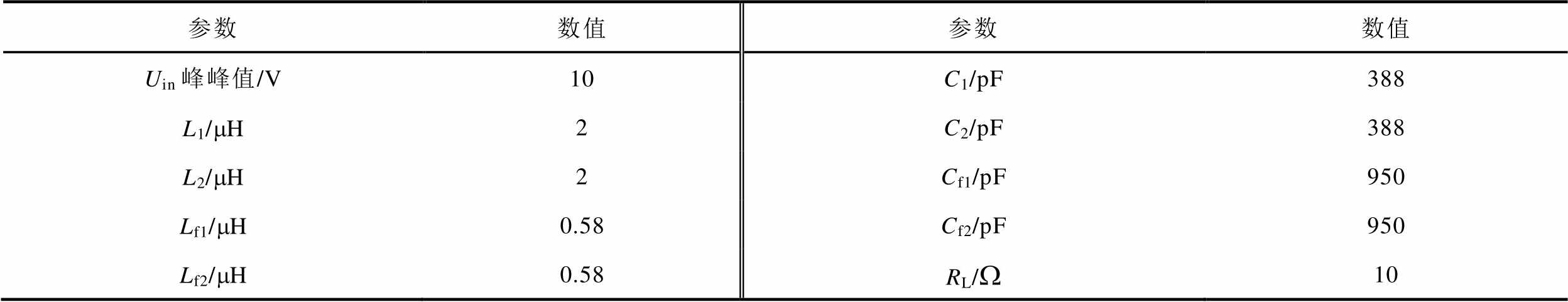
参数数值参数数值 Uin峰峰值/V10C1/pF388 L1/mH2C2/pF388 L2/mH2Cf1/pF950 Lf1/mH0.58Cf2/pF950 Lf2/mH0.58RL/W10
在12 mm的传输距离下,实验对比了非集成MCR-WPT系统与集成MCR-WPT系统的输入输出特性,其波形分别如图11和图12所示。相比于非集成MCR-WPT系统,集成MCR-WPT系统的传输效率由62.3%提高到了68.1%,输出功率由0.89 W提高至1.28 W。
为了进一步验证本文所提出的基于LCC-LCC的集成式结构的抗偏移能力,分别对非集成MCR-WPT系统与集成MCR-WPT系统进行了横向偏移以及角度偏移实验,通过移动接收端来研究不同位置对系统状态的影响。
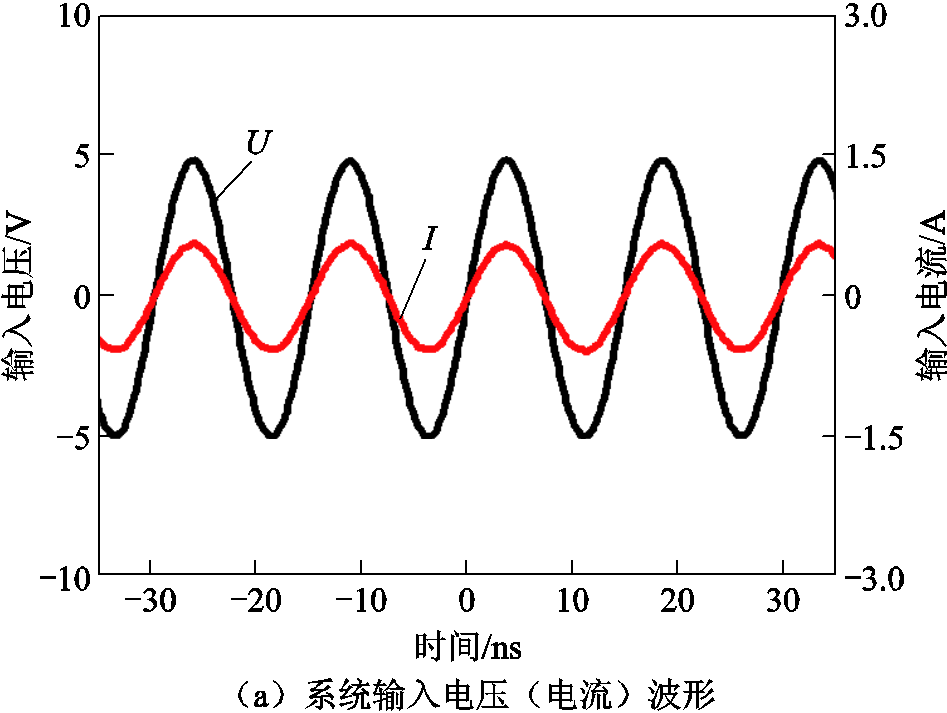
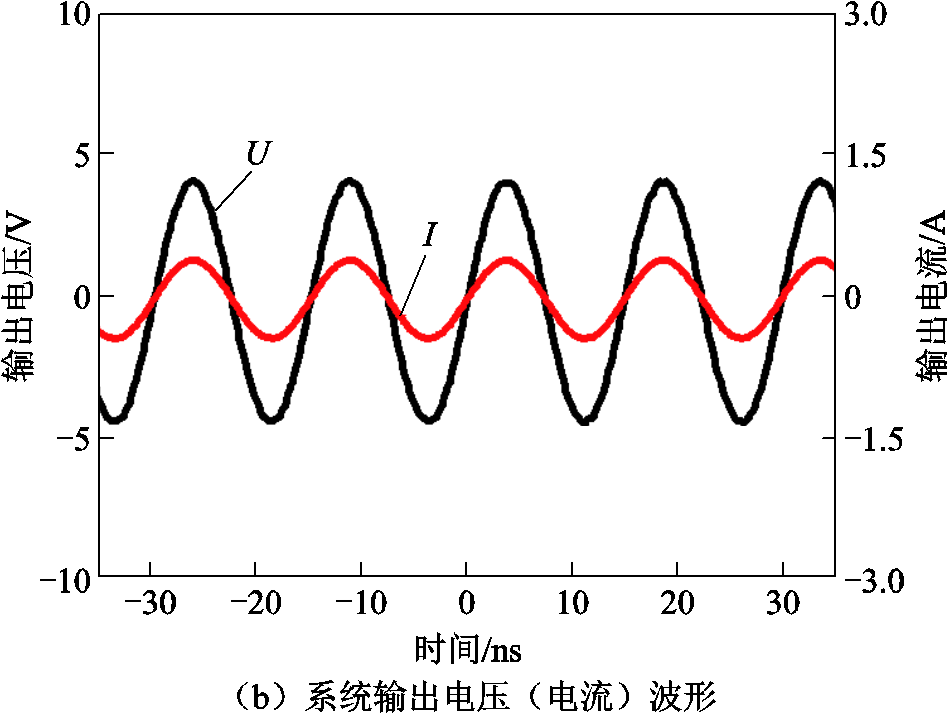
图11 非集成MCR-WPT系统电压(电流)波形
Fig.11 Voltage (current) waveform of non-integrated MCR-WPT system
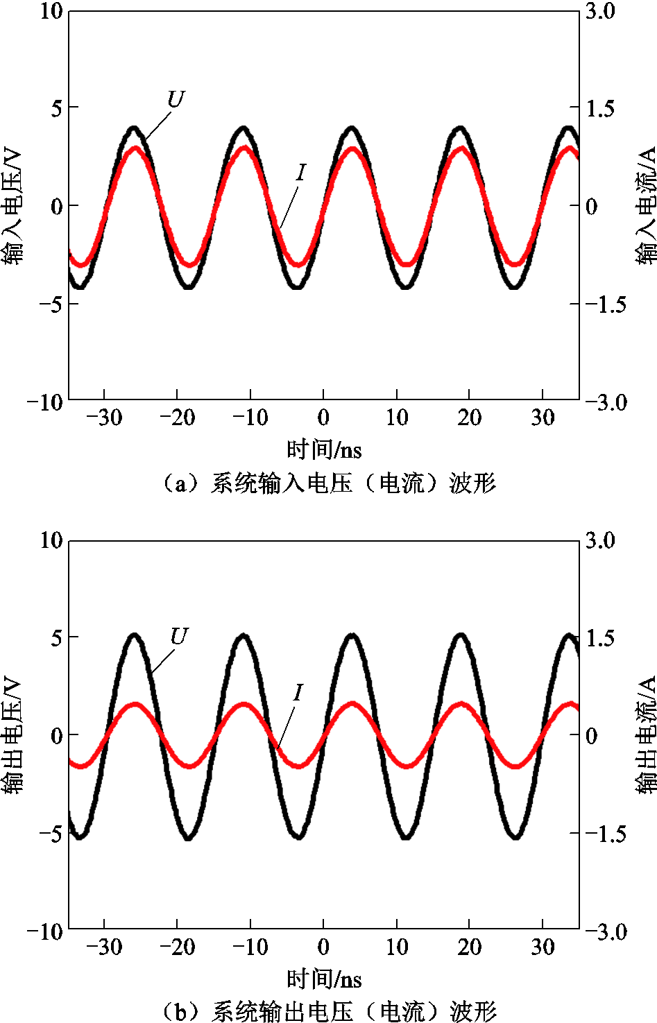
图12 集成MCR-WPT系统电压(电流)波形
Fig.12 Voltage (current) waveform of integrated MCR-WPT system
横向偏移实验中,将线圈的发射端和接收端正对,并将它们的初始位置设置在轴向间距为12 mm处。从起始点开始,以5 mm为一个步长,横向移动接收端至20 mm处,绘制出传输效率随横向偏移位置变化的曲线,如图13所示。在接收端横向偏移 20 mm时,集成MCR-WPT系统相较于非集成MCR-WPT系统传输效率由19.5%提升至36.8%。
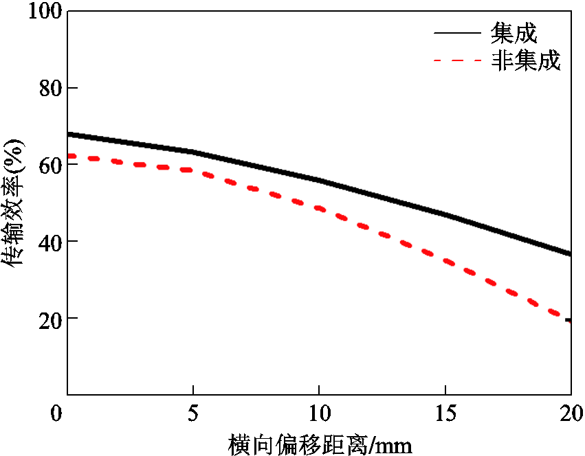
图13 线圈横向偏移对传输效率的影响
Fig.13 The influence of coil lateral offset on transmission efficiency
角度偏移实验中,在确保发射端与接收端之间12 mm的最小距离的情况下,以发射线圈的一侧为轴,改变接收端的旋转角度(范围为0°~60°,步长为15°),记录不同旋转角对传输效率的影响,并绘制两者之间的关系曲线,如图14所示。实验结果表明,在接收端偏移15°和30°时,集成MCR-WPT系统相较于非集成MCR-WPT系统传输效率提升较为明显,传输效率分别由33.7%、19.7%提升至59.6%、32.3%。
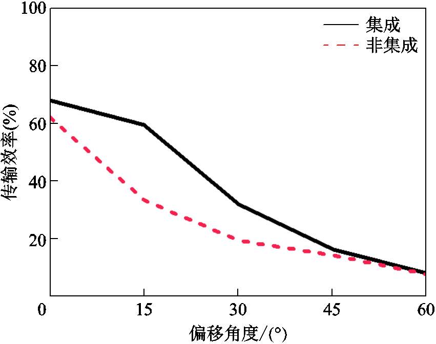
图14 线圈角度偏移对传输效率的影响
Fig.14 The influence of coil angle offset on transmission efficiency
对于心脏起搏器无线电能传输系统,除了考虑传输效率、抗偏移能力之外,还需要进行可行性问题评估,其中包括电磁场对健康的潜在影响。国际非电离辐射防护委员会(ICNRP)[24]和电气电子工程师协会(IEEE)[25]对体内电场强度以及比吸收率(SAR)进行了职业暴露基本限制,基本限制参数见表5。
表5 职业暴露基本限制参数
Tab.5 Basic limiting parameters for occupational exposure
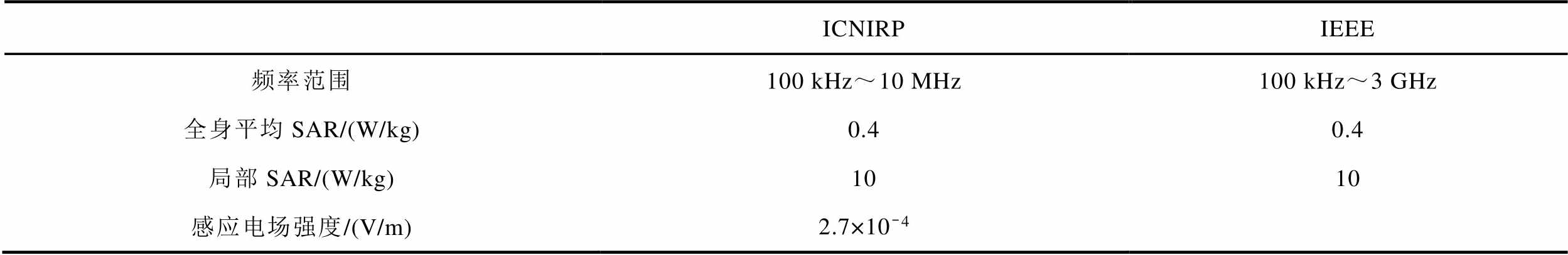
ICNIRPIEEE 频率范围100 kHz~10 MHz100 kHz~3 GHz 全身平均SAR/(W/kg)0.40.4 局部SAR/(W/kg)1010 感应电场强度/(V/m)2.7×10-4
由表5中可得出,在无线电能传输系统中,对于人体局部的暴露,通常规定10 g组织的峰值空间平均SAR值不应超过10 W/kg。此时,ICNIRP要求局部暴露于电磁场的参考峰值在6.78 MHz频率下应为1 830.6 V/m。
为了准确模拟植入式心脏起搏器无线电能传输系统的性能,本文利用Ansys HFSS建立了由头部、心脏、皮肤、皮下脂肪、肌肉等组成的人体上半身三维模型。根据文献[26]中生物组织的介电特性,本文计算了在6.78 MHz频率下的人体各组织相对介电常数以及电导率参数,并将这些参数导入人体模型中,具体的参数见表6。
表6 6.78 MHz下的人体组织参数
Tab.6 Human tissue parameters at 6.78 MHz
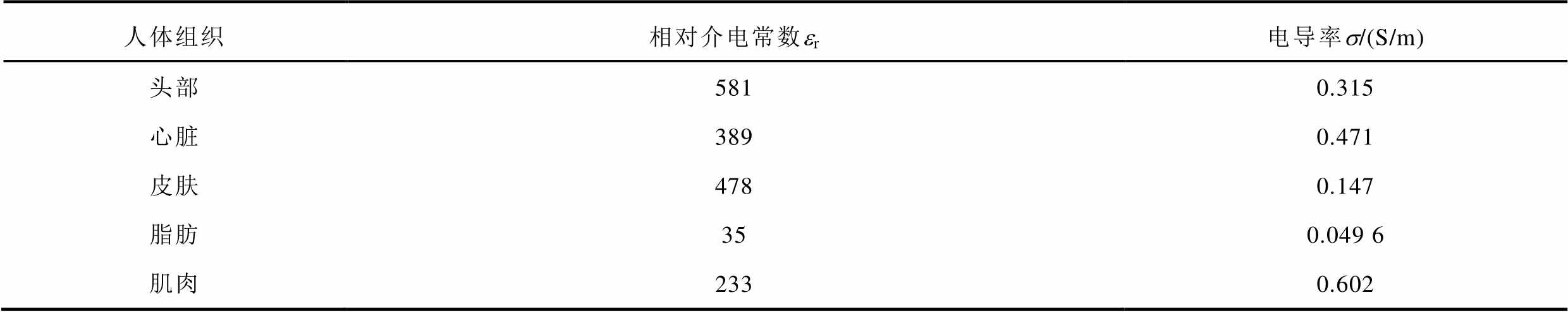
人体组织相对介电常数er电导率s/(S/m) 头部5810.315 心脏3890.471 皮肤4780.147 脂肪350.049 6 肌肉2330.602
将无线电能传输系统放置于人体模型中,在6.78 MHz的频率下,系统工作时人体内部各个组织的SAR值以及电场强度分布如图15和图16所示。

图15 人体SAR值分布
Fig.15 SAR value distribution of human body

图16 人体电场强度分布
Fig.16 Electric field intensity distribution of human body
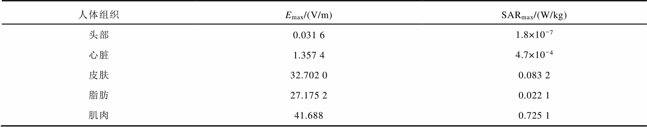
人体内部各个组织的最大电场强度与SAR值见表7。根据表7仿真数据可知,头部产生的最大电场强度与SAR值分别仅为0.031 6 V/m和 W/kg,这表明头部在无线充电系统的能量传输过程中受到的影响非常微弱,不会对其正常功能产生影响。对于距离无线充电系统较近的心脏组织,最大电场强度与SAR值分别为1.357 4 V/m和
 W/kg,仍处于安全范围内;对于整个上半身范围内,最大的电场强度与SAR值出现在发射线圈与接收线圈之间的胸肌处,分别为41.688 V/m和0.725 1 W/kg,虽然相对于其他组织较高,但远低于ICNIRP指南以及IEEE标准所提出的职业暴露基本限制参数。因此,该充电系统在充电过程中满足电磁安全性的规定标准。
表7 人体内部各个组织的最大电场强度与SAR值
Tab.7 The maximum electric field intensity and SAR value of each tissue in the human body
人体组织Emax/(V/m)SARmax/(W/kg) 头部0.031 61.8×10⁻⁷ 心脏1.357 44.7×10⁻⁴ 皮肤32.702 00.083 2 脂肪27.175 20.022 1 肌肉41.6880.725 1
为减小植入式心脏起搏器无线充电系统的体积,简化植入电路结构,本文提出了一种基于LCC-LCC磁集成PSC的心脏起搏器无线电能传输系统。
通过建立线圈模型分析在填充比率固定情况下PSC的匝宽和匝间距对传输效率的影响,确定了最佳的PSC结构。建立非集成式和集成式耦合机构仿真模型,计算了其在不同偏移条件下的磁场分布情况。同时,对比了非集成MCR-WPT系统和集成MCR-WPT系统,实验结果表明,集成结构相较于非集成结构在抗偏移能力以及传输效率方面更具优势。
此外,对系统进行了安全评估,模拟计算了无线充电过程中电场强度和SAR值在人体内的分布情况,证明了该系统在充电过程中满足电磁安全性的规定标准。
本文通过将独立电感以线圈形式整合到主线圈中,成功地减小了系统体积,提高了集成度。这对于心脏起搏器无线充电系统在利用PSC作为磁耦合集成结构的研究方面提供了一定的参考价值。此外,对于植入式传能系统的标准化生产起到了积极的推动作用,有助于推进系统产品化进程。下一步的研究需要采用活体动物实验进行系统的安全评估,以进一步确保该系统的安全性。
参考文献
[1] Santini M, Cappato R, Andresen D, et al. Current state of knowledge and experts’perspective on the subcutaneous implantable cardioverter-defibrillator[J]. Journal of Interventional Cardiac Electrophysiology, 2009, 25(1): 83-88.
[2] Park S W, Wake K, Watanabe S. Incident electric field effect and numerical dosimetry for a wireless power transfer system using magnetically coupled resonances [J]. IEEE Transactions on Microwave Theory and Techniques, 2013, 61(9): 3461-3469.
[3] Sunohara T, Hirata A, Laakso I, et al. Analysis of in situ electric field and specific absorption rate in human models for wireless power transfer system with induction coupling[J]. Physics in Medicine and Biology, 2014, 59(14): 3721-3735.
[4] Zhao Jinwei, Ghannam R, Yuan Mengyao, et al. Design, test and optimization of inductive coupled coils for implantable biomedical devices[J]. Journal of Low Power Electronics, 2019, 15(1): 76-86.
[5] Kurs A, Karalis A, Moffatt R, et al. Wireless power transfer via strongly coupled magnetic resonances[J]. Science, 2007, 317(5834): 83-86.
[6] 陈伟华, 侯海涛, 闫孝姮, 等. 基于混合磁负超材料的心脏起搏器无线供能系统[J]. 电工技术学报, 2023, 38(4): 865-878.
Chen Weihua, Hou Haitao, Yan Xiaoheng, et al. Wireless energy supply system for cardiac pacemaker based on hybrid mu-negative metamaterials[J]. Transactions of China Electrotechnical Society, 2023, 38(4): 865-878.
[7] Xiao Chunyan, Wei Kangzheng, Cheng Dingning, et al. Wireless charging system considering eddy current in cardiac pacemaker shell: theoretical modeling, experiments, and safety simulations[J]. IEEE Transa-ctions on Industrial Electronics, 2017, 64(5): 3978-3988.
[8] Xiao Chunyan, Cheng Dingning, Wei Kangzheng. An LCC-C compensated wireless charging system for implantable cardiac pacemakers: theory, experiment, and safety evaluation[J]. IEEE Transactions on Power Electronics, 2018, 33(6): 4894-4905.
[9] 闫孝姮, 黄明鑫, 陈伟华. 无SAR评估条件下心脏起搏器谐振式无线供能系统研究[J]. 仪器仪表学报, 2020, 41(5): 185-195.
Yan Xiaoheng, Huang Mingxin, Chen Weihua. Research on the resonant wireless energy supply system of pacemaker without SAR evaluation[J]. Chinese Journal of Scientific Instrument, 2020, 41(5): 185-195.
[10] Xiao Chunyan, Hao Sihui, Cheng Dingning, et al. Safety enhancement by optimizing frequency of implantable cardiac pacemaker wireless charging system[J]. IEEE Transactions on Biomedical Circuits and Systems, 2022, 16(3): 372-383.
[11] 薛明, 杨庆新, 章鹏程, 等. 无线电能传输技术应用研究现状与关键问题[J]. 电工技术学报, 2021, 36(8): 1547-1568.
Xue Ming, Yang Qingxin, Zhang Pengcheng, et al. Application status and key issues of wireless power transmission technology[J]. Transactions of China Electrotechnical Society, 2021, 36(8): 1547-1568.
[12] 沈栋, 杜贵平, 丘东元, 等. 无线电能传输系统电磁兼容研究现况及发展趋势[J]. 电工技术学报, 2020, 35(13): 2855-2869.
Shen Dong, Du Guiping, Qiu Dongyuan, et al. Research status and development trend of electromagnetic compatibility of wireless power transmission system[J]. Transactions of China Electrotechnical Society, 2020, 35(13): 2855-2869.
[13] 孙淑彬, ,张波, 李建国, 等. 多负载磁耦合无线电能传输系统的拓扑发展和分析[J]. 电工技术学报, 2022, 37(8): 1885-1903.
Sun Shubin, Zhang Bo, Li Jianguo, et al. Topology development and analysis of multi-load magnetically coupled wireless energy transmission systems[J]. Transactions of China Electrotechnical Society, 2022, 37(8): 1885-1903.
[14] Campi T, Cruciani S, Palandrani F, et al. Wireless power transfer charging system for AIMDs and pacemakers[J]. IEEE Transactions on Microwave Theory and Techniques, 2016, 64(2): 633-642.
[15] 周豪, 姚钢, 赵子玉, 等. 基于LCL谐振型感应耦合电能传输系统[J]. 中国电机工程学报, 2013, 33(33): 2, 9-16.
Zhou Hao, Yao Gang, Zhao Ziyu, et al. LCL resonant inductively coupled power transfer systems[J]. Proceedings of the CSEE, 2013, 33(33): 2, 9-16.
[16] Ali N, Liu Z, Hou Y, et al. LCC-S based discrete fast terminal sliding mode controller for efficient charging through wireless power transfer[J]. Energies, 2020, 13(6): 1370.
[17] Li Siqi, Li Weihan, Deng Junjun, et al. A double-sided LCC compensation network and its tuning method for wireless power transfer[J]. IEEE Transactions on Vehicular Technology, 2015, 64(6): 2261-2273.
[18] Qu Xiaohui, Jing Yanyan, Han Hongdou, et al. Higher order compensation for inductive-power-transfer converters with constant-voltage or constant-current output combating transformer parameter constraints[J]. IEEE Transactions on Power Electronics, 2017, 32(1): 394-405.
[19] 郭星, 刘利强, 齐咏生, 等. 基于LCL-LCL/S混合自切换谐振式无线充电系统[J]. 电工技术学报, 2022, 37(10): 2422-2434.
Guo Xing, Liu Liqiang, Qi Yongsheng, et al. Hybrid self-switching resonant wireless charging system based on LCL-LCL/S[J]. Transactions of China Electrotechnical Society, 2022, 37(10): 2422-2434.
[20] Kan Tianze, Nguyen T D, White J C, et al. A new integration method for an electric vehicle wireless charging system using LCC compensation topology: analysis and design[J]. IEEE Transactions on Power Electronics, 2017, 32(2): 1638-1650.
[21] Lu Fei, Zhang Hua, Hofmann H, et al. A dual-coupled LCC-compensated IPT system with a compact magnetic coupler[J]. IEEE Transactions on Power Electronics, 2018, 33(7): 6391-6402.
[22] Mosammam B M, Mirsalim M. New integrated tripolar pad using double-sided LCC compensation for wireless power transfer[J]. IEEE Transactions on Vehicular Technology, 2020, 69(12): 15633-15643.
[23] Jow U M, Ghovanloo M. Design and optimization of printed spiral coils for efficient transcutaneous inductive power transmission[J]. IEEE Transactions on Biomedical Circuits and Systems, 2007, 1(3): 193-202.
[24] International Commission on Non-Ionizing Radiation Protection (ICNIRP). Guidelines for limiting exposure to time-varying electric, magnetic, and electromagnetic fields (up to 300 GHz)[J]. Health Physics, 1998, 74(4): 494-522.
[25] Lin J C. A new IEEE standard for safety levels with respect to human exposure to radio-frequency radiation[J]. IEEE Antennas and Propagation Magazine, 2006, 48(1): 157-159.
[26] Gabriel S, Lau R W, Gabriel C. The dielectric properties of biological tissues: III. parametric models for the dielectric spectrum of tissues[J]. Physics in Medicine and Biology, 1996, 41(11): 2271-2293.
Research on Wireless Power Transmission for Cardiac Pacemakers Using LCC-LCC Magnetic Integrated Printed Spiral Coil
Abstract Cardiac pacemakers, reliant on lithium batteries, necessitate frequent surgical replacements due to limited capacity. Magnetically coupled resonant wireless power transfer (MCR-WPT) technology holds substantial potential for implanted medical devices, but challenges such as transmission efficiency and safety require resolution. In the MCR-WPT system, the composite compensation topology enhances system robustness under offset conditions while meeting constant voltage or constant current output requirements. However, the independent inductance contributes to an increased volume, constraining its application in implantable devices. To address this issue, this paper proposes a wireless power transmission system for cardiac pacemakers based on the LCC-LCC magnetically integrated printed spiral coil (PSC), achieved by incorporating the compensation inductor into the main coil in concentric circles.
By constructing a coil model to analyze the impact of turn width and turn spacing on the transmission efficiency of PSC under a fixed filling ratio, the optimal PSC structure is determined. Simulation models for non-integrated and integrated coupling mechanisms are established, and the magnetic field distribution is calculated under lateral and angle offset conditions. Concurrently, a comparison is made between the non-integrated MCR-WPT system and the integrated MCR-WPT system. Experimental results demonstrate that the integrated structure exhibits superior anti-offset capability and transmission efficiency compared to the non-integrated counterpart. At a frequency of 6.78 MHz, the integrated MCR-WPT system achieves a transmission efficiency of 68.1% and an output power of 1.28 W. In comparison with the non-integrated structure, the integrated structure shows a 5.8% increase in transmission efficiency and a 0.39 W boost in output power. In the offset experiment, a horizontal offset of 20 mm for the receiver results in a notable enhancement in the transmission efficiency of the integrated MCR-WPT system, rising from 19.5% to 36.8% compared to the non-integrated MCR-WPT system. Similarly, for receiver offsets at 15° and 30° angles, the transmission efficiency of the integrated MCR-WPT system surpasses that of the non-integrated counterpart significantly. In these instances, the transmission efficiency escalates from 33.7% to 59.6% at 15° and from 19.7% to 32.3% at 30°.
Furthermore, a three-dimensional model of the human upper body is constructed for the safety assessment of the system. The simulation includes the analysis of the distribution of electric field intensity and SAR (specific absorption ratio) value in the human body during wireless charging. Results indicate that during the operation of the MCR-WPT system, the peak values of electric field intensity and SAR value in human tissue are 41.688 V/m and 0.725 1 W/kg, respectively. These values fall below the ICNIRP guidelines and IEEE standards. The international radiation safety limit standard proposed by the standard aligns with safety specifications, affirming that the system meets electromagnetic safety requirements during charging.
This paper integrates independent inductance into the main coil in a coil form, effectively reducing system volume and enhancing integration. This offers valuable insights for the exploration of a wireless charging system for cardiac pacemakers utilizing PSC as a magnetic coupling integrated structure. Additionally, it contributes positively to advancing the standardized production of implantable energy transfer systems, facilitating progress in system productization.
keywords:Wireless power transmission, pacemaker, magnetic integration, printed spiral coil (PSC)
中图分类号:TM724
DOI: 10.19595/j.cnki.1000-6753.tces.231199
2020年辽宁省教育厅科学研究青年科技人才“育苗”项目(LJ2020QNL019)和2023年辽宁省教育厅科学技术研究面上项目(JYTMS20230815)资助。
收稿日期 2023-07-25
改稿日期 2023-11-10
陈伟华 男,1980年生,博士,副教授,研究方向为无线电能传输。
E-mail:fxlgd@163.com
宋宇航 男,1998年生,硕士,研究方向为无线电能传输。
E-mail:six17h@outlook.com(通信作者)
(编辑 郭丽军)