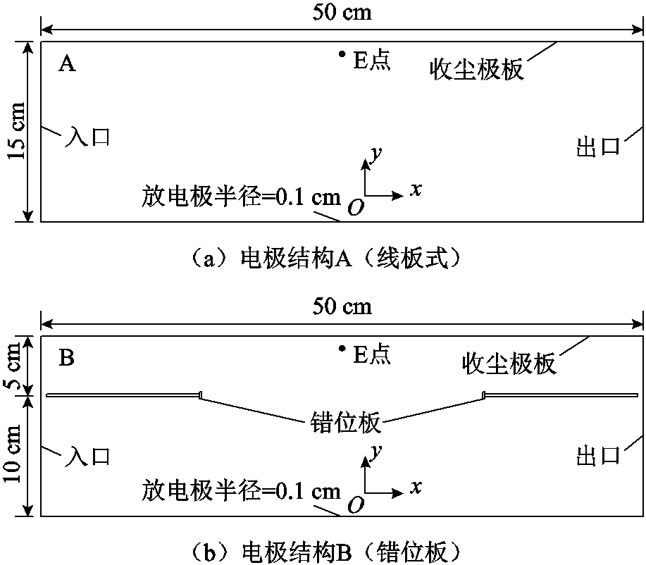
图1 线板式和错位板式电极结构
Fig.1 Structures of wire board and dislocation board electrodes
摘要 为了进一步提高电除尘器的除尘效率,该文采用数值模拟与实验相结合的方法研究了电极结构对电除尘器内电场特性及电流体场分布的影响。使用高速离子射流耦合电流体场的模拟方法建立了数值模型,分析了电除尘器内电流体状态及阳极板附近流速,同时使用粒子图像测速法对两种电极结构在不同电压下的电流体状态进行了测定。结果表明,错位板结构可以增强电晕放电强度,降低起晕电压,相较于线板式结构,起晕电压降低了29.41%,电晕电流提升近一倍。电压越高,电流体场受放电极产生的高速离子射流影响越大。入口风速会影响电流体场状态,当入口风速为0 m/s时,电流体状态呈对称的双螺旋结构;入口风速提升至0.1 m/s时,涡旋被挤压变形;继续增大入口风速,涡旋变形程度加大,且靠近入口处涡旋消失。错位板结构能显著降低收尘极板附近流速,当入口风速为0.9 m/s时,线板式与错位板除尘器收尘极板前1 cm平均流速分别为1.28 m/s和0.68 m/s。相比于采用普通的多物理场耦合方法,采用高速离子射流耦合电流体场方法得到的模拟结果与实验结果更加符合。
关键词:电流体场 错位板 离子风 数值模拟 粒子图像测速法
21世纪以来,针对空气质量这一问题,国家陆续出台了《大气污染防治行动计划》《打赢蓝天保卫战三年行动计划》《深入打好重污染天气消除、臭氧污染防治和柴油货车污染治理攻坚战行动方案》等多项措施,这对除尘器性能提出了更高的要求。由于电除尘器具有运行成本低、收集率高和维护简单的优点[1-2],在实际中被普遍应用。电除尘器中电晕放电被用来控制粒子的运动,其通过电晕放电使离子从一个电极移动到另一个电极,离子与中性粒子碰撞产生电流体动力学(Electrohydrodynamic, EHD)气流运动[3-6],其中带电粒子主要沿电场线运动,中性粒子则随着气流一起运动[7-8]。
为了提升电除尘器的性能,学者们提出了不同的电除尘器电极结构。Chen Bing等[9]模拟了7种收尘极板形状对收尘效率的影响。沈恒等[10]研究了波形板与C型板电除尘器的性能。C. Bacher等[11]通过实验研究了不同阴极线管式电除尘器的收集率。邓杰文等[12]对3种板型下荷电粒子在除尘空间的运动过程进行了定量分析。Zheng Chenghang等[13]研究了4种电极配置下两种粒子的运动状态和去除效率。
事实上,电极结构的改变会对流场分布产生影响,而流场对粒子的运动至关重要。G. L. Leonard等[14]进行激光风速测量实验,验证了负电晕放电的不均匀性是在平行于放电线的平面内产生二次流的原因。Guo Jun等[15]研究了静电除尘器中的电流体动力学效应,结果表明,EHD通常会增大收尘极板附近的流速,导致电除尘器性能下降。沈欣军等[16]采用粒子图像测速法(Particle Image Velocimetry, PIV)对线板式除尘器内的流场进行了研究。H. Y. Choi等[17]模拟了不同波形的波浪板流场分布。闫东杰等[18]采用PIV技术研究了芒刺线板式电除尘器内部流场。李庆等[19]对孔板结构下离子风的流场分布进行研究,证明了改变电极结构有助于减小离子风对粒子收集的消极影响。Feng Zhuangbo等[20]采用一种混合方法,包括模拟电离电场的有限元法和预测电除尘器模拟中的EHD流量的有限体积法,并通过Qkubo-Weiss指数对电晕诱导的EHD流进行了定量分析。
本文基于COMSOL仿真软件,使用高速离子射流耦合电流体场的模拟方法构建线板式及错位板电除尘器数值模型,对比分析两模型的电势、空间电荷密度分布,重点对电流体特性及收尘极板附近流速进行研究,并用PIV技术测定两种电除尘器在不同电压下的电流体分布,分析电流体特性随电晕电压增长而变化的状态。
为研究不同电极结构对电除尘器的影响,建立了错位板式电除尘器,并将传统线板式除尘器作为对照,研究电极结构对电流体场分布的影响。为便于分析,分别将线板式除尘器与错位板式除尘器称为A、B电极结构,以放电极中心为原点设定坐标系,两种电极结构如图1所示。错位板是基于线板式增设两块收尘极板,将靠近中心处设置为T状,且放电极距错位板最近处大于结构A线板距,入口与出口宽度减小为结构A的2/3。
图1 线板式和错位板式电极结构
Fig.1 Structures of wire board and dislocation board electrodes
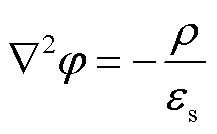
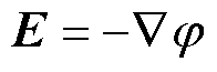
假设带电粒子不影响电学特性,电晕电场可由泊松电势方程与电流连续性方程确定[21]。
 (1)
(1)
 (2)
(2)
 (3)
(3)
 (4)
(4)
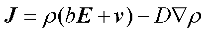
式中,φ为空间电势;ρ为空间电荷密度; 为空间中的介电常数;E为电场强度矢量;J为电流密度矢量;b为离子迁移率;v为气流速度矢量;D为离子扩散系数。
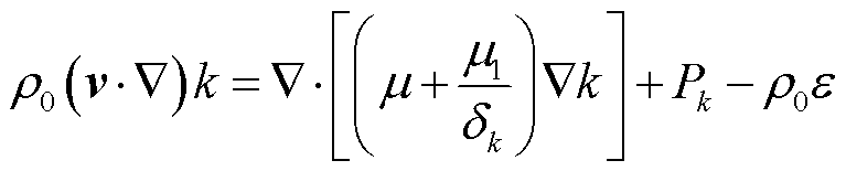
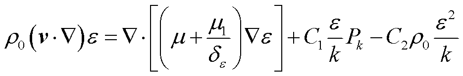
标准的k-ε模型[22]由湍动能方程和耗散率方程组成,见式(5)~式(7)。采用Navier-Stokes方程和质量守恒的连续性方程进行求解,见式(8)和式(9)。
 (5)
(5)
 (6)
(6)
 (7)
(7)
 (8)
(8)
 (9)
(9)
式中,k为湍流动能;ε为湍流耗散率;δk和δε分别为k、ε的普朗特数,其值分别为0.9和1.3;ρ0为流体密度;μ为层流黏度;μ1为湍流黏度;Pk为湍动能每单位耗散净产出;p1为气体静压力; 为单位矩阵;
 为其他外力;C1、C2、C3为常量,其值分别为1.44、1.92、0.09。
模型网格划分如图2所示。为了保证结果的准确性,对A、B电极结构的极板、电极附近进行网格加密,增设5层边界层,如图2a所示。结构B的T状结构会引起附近电场骤变与流场紊乱,因此对T状结构处网格进行局部加密,如图2b所示。其余网格均采用物理场控制网格方式进行划分,如图2c和图2d所示。

图2 网格划分
Fig.2 Mesh generation
入口与出口不发生电晕放电,故均设置为零电荷。入口边界设为充分发展的流动,出口边界设为静压出口,抑制回流。放电极边界设置Dirichlet边界条件,收尘极板接地。
对上述方程进行联立求解,可以得到电势、空间电荷密度、风速等电流体特性。从模拟结果可知,虽然利用此方法计算得到的放电空间的风速与实验结果从定性角度上看相同,但是从定量角度来看差距较大。而通过引入下文所述高速离子射流源可以使模拟和实验结果更加符合。
在放电极发生电晕放电时,放电的电离、激发以及高速离子移动主要发生在电极周围mm量级的范围内,此处称为电晕区。从电流体角度分析,电极附近的放电为一高速离子风源,即离子风射流。离子风射流是由放电极区域的电晕区产生,通过实验难以研究电晕区内部的复杂状态,而电晕区尺寸较小,相较于除尘空间可以忽略。因此,在研究流场时,基于上述方程,将放电极周围1 mm仅看作高速离子射流源,在流场控制方程中假设存在一初始风速,双向耦合新增设高速离子射流源与电流体场方程,用来拟合离子风射流对电流体场的扰动,并依据课题组数据[23-25]及实验所测实际风速,当电压分别为35、40、45、50 kV时,将放电极周围初始射流风速分别设定为5.76、10.82、15.68、19.53 m/s。
为了验证该改进模型的可靠性,依据G. W. Penney等实验[26]中线板式静电除尘器结构,在COMSOL中构建1:1的模型,采用高速离子射流耦合电流体场方法模拟,得到了x=0 mm处放电极与收尘极板轴线上的电势分布,如图3所示。结果表明,实验值和模拟值具有较好的一致性,证明了改进模型的可靠性。
为了比较第1节所述普通多物理场耦合模型和改进后的高速离子射流耦合电流体场模拟方法,分别采用两种方法模拟得到了图1中近板处E点的风速值,如图4所示。图4为采用原方法和改进的高速离子射流耦合电流体场模拟方法拟合出的近板处E点风速值与实验值的对比。可见原方法计算得到的风速与实验所测风速差距较大;高速离子射流耦合电流体场模拟数值与实测数据随电压变化趋势一致,且数值相较原方法数值更贴合实验结果。综合35~55 kV电压下的模拟结果,高速离子射流耦合电流体场模拟方法得出的数值与实验数据之间的误差不超过5%,具有较高的吻合度,验证了该方法的可行性。
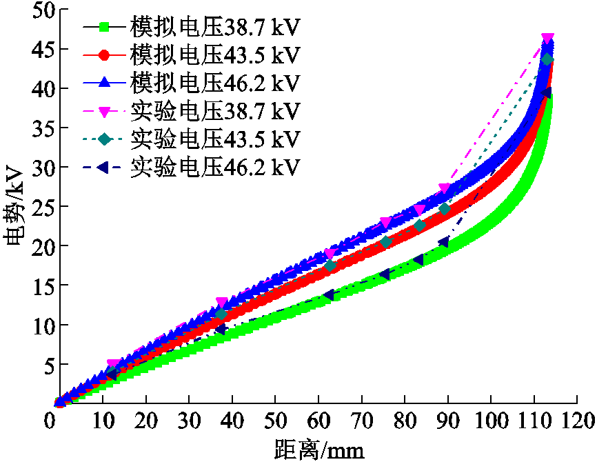
图3 不同电压下电势模拟值与实验值对比
Fig.3 Comparison between simulated and experimental values of electric potential under different voltages
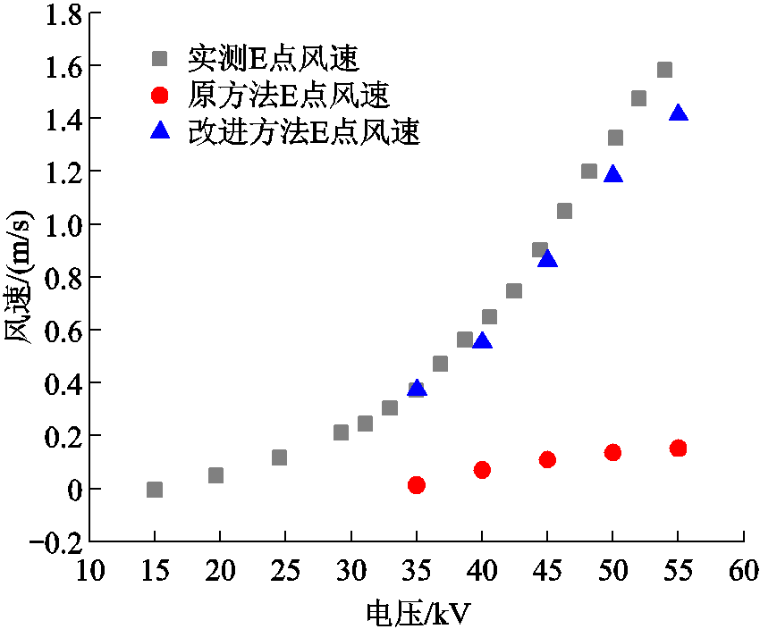
图4 E点处风速模拟值与实验值对比
Fig.4 Comparison between simulated values and experimental results of wind speed at point E
实验装置示意图如图5所示。实验系统主要包括烟雾发生系统、负高压直流电源、μA级电流表、激光源、高速摄像机、除尘器主体。烟雾发生系统型号为CSM-MO,可控制流速为0~1.5 m/s。激光源型号为SM-SEMI-10W,通过调节功率来控制激光强度。高速摄像机型号为PCO.dimaxS1。
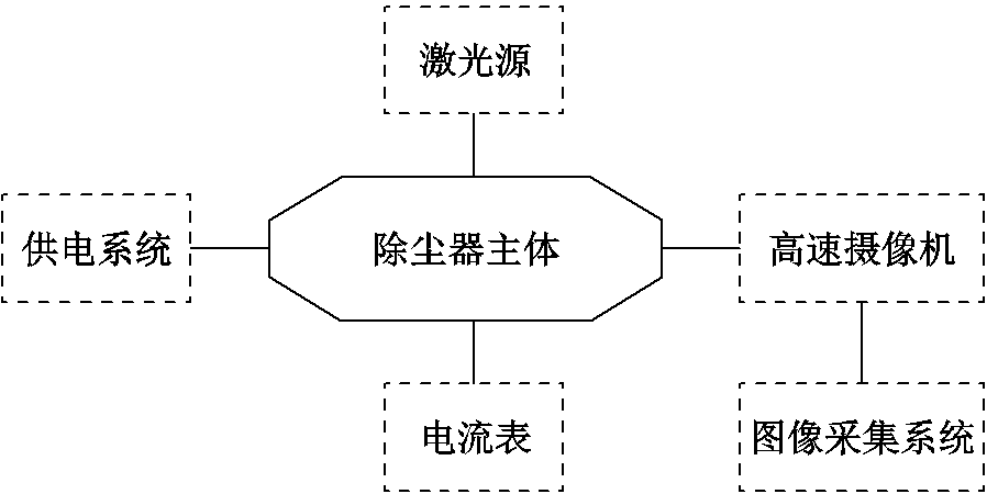
图5 实验装置示意图
Fig.5 Experimental device
图6和图7分别为y=95 mm处电势、电场强度的对比。由于错位板结构的存在,放电极对T状结构存在尖端放电,在入口与出口方向电压降增大。且在T状结构处,结构B电场强度约为结构A的4倍,灰尘颗粒受到y轴方向的力也较大,向收尘极板运动的趋势更明显,这将提升颗粒到达收尘极板的概率。

图6 电压45 kV时y=95 mm两电极结构电势对比
Fig.6 Comparison of potential between two electrode structures with y=95 mm at a voltage of 45 kV
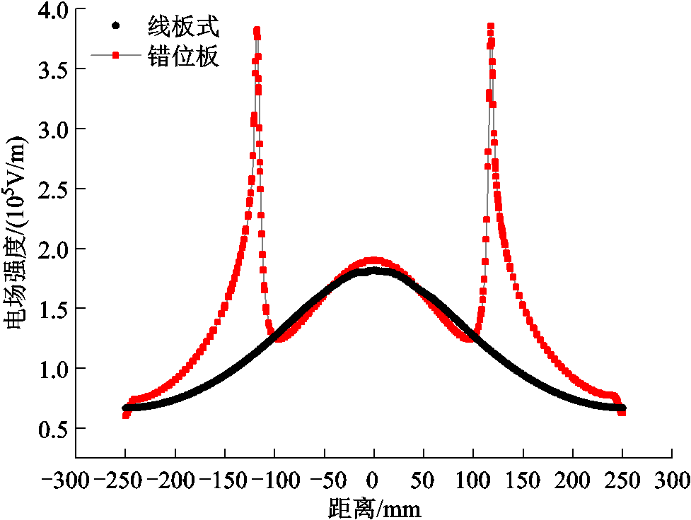
图7 电压45 kV时y=95 mm两电极结构电场强度对比
Fig.7 Comparison of electric field strength between two electrode structures with y=95 mm at a voltage of 45 kV
y=75 mm处两电极结构空间电荷密度对比如图8所示。A、B电极结构均在电极正对收尘极板方向达到最大值,但结构A空间电荷密度值均小于结构B,在峰值处差值最大,结构B较结构A提高了40%。两模型除尘器伏安特性对比如图9所示,结构A起晕电压为15 kV,结构B起晕电压仅为10 kV。电晕电流均随着电压的增加而增大,当电压为25 kV时,A、B电极结构电晕电流分别为6.7 μA、12.8 μA,结构B约为结构A的2倍;当电压上升至45 kV时,仍保持此规律。结果表明,错位板结构可以降低起晕电压,提升空间内电晕放电强度。
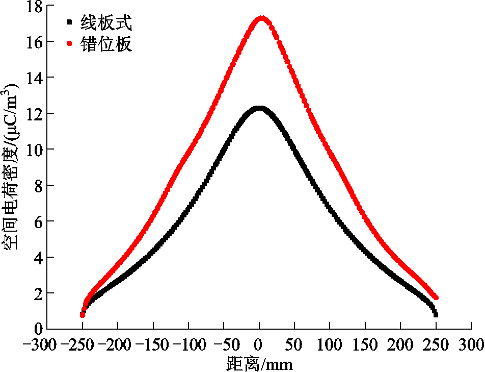
图8 y=75 mm处两电极结构空间电荷密度对比
Fig.8 Comparison of space charge density between two electrode structures at y=75 mm
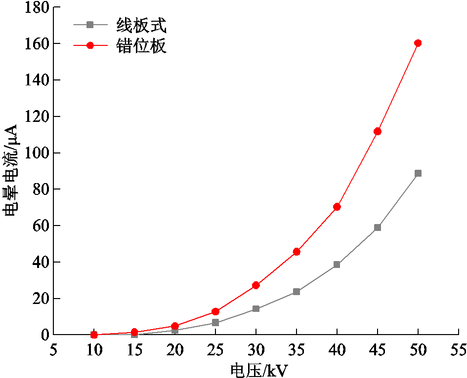
图9 两电极结构除尘器伏安特性对比
Fig.9 Comparison of voltage-ampere characteristics of two electrode structure dust removers
电压为45 kV、无入口风速时两模型整体流场分布如图10所示,此时高速离子射流占主导地位。无入口风速时,结构A在两侧形成一对镜像双螺旋结构的涡旋;结构B由于错位板结构呈两对镜像双螺旋结构的涡旋,为便于分析,将其从左到右依次命名为旋1、旋2、旋3、旋4。对于结构B,当粒子跟随流场运动时,会被旋2携带至后收尘极板,部分会脱离涡旋进入左错位板与后收尘极板之间被收集,未被收集的粒子跟随旋2出来后,继续跟随旋3进入右错位板与后收尘极板之间,之后又重复上一过程,进一步提升了粒子的停留时间,增大被捕集的概率。

图10 电压45 kV无入口风速时两电极结构流场分布
Fig.10 Flow field distribution of two electrode structure with voltage of 45 kV and no inlet wind speed
电压为40 kV、不同入口风速时两电极结构流场分布如图11所示。当风速为0.1 m/s时,如图11a、图11b所示,两电极结构涡旋均有一定变化,其中,结构A电极左侧风旋向上收尘极板偏移,电极右侧涡旋向下偏移;结构B旋1向错位板贴近,旋2向偏移到错位板与后收尘极板间,旋3向下偏移,旋4向错位板偏移。风速增大至0.3 m/s时,如图11c、图11d所示,结构A电极左侧涡旋消失,电极右侧涡旋向下偏移量增大,且涡旋形状近似椭圆形;结构B旋1消失,旋2边缘移动至后收尘极板,且涡旋缩小至初始时的1/3,旋3向右下方偏移量增大,旋4的涡旋中心偏移至错位板。当风速继续增大时,结构A右侧涡旋继续向下偏移,结构B旋2已完全被挤压至错位板与后收尘板间,旋3向下偏移量增大,涡旋面积继续减小,旋4继续贴近错位板,涡旋变形严重。整体来看,随着入口风速的增大,涡旋均发生严重变形,且结构B流速均低于结构A。通过对比图11中两种结构的流场分布发现,相较于结构A,结构B中部分粒子会在流场的作用下进入错位板与后收尘极板间,跟随错位板与后收尘极板间的涡旋运动,之后再向出口运动。同时由图12和图13的结果可知,错位板板前1 cm处风速低于线板式。因此尘埃粒子在除尘器中的滞留时间会增大,从而提升除尘效率[27]。

图11 电压40 kV不同入口风速流场分布
Fig.11 Distribution of flow field at different inlet wind speeds with voltage of 40 kV
在电除尘器实际运行中,收尘极板附近气流状态决定了二次扬尘的强弱,并影响除尘效率。故取结构A收尘极板板前1 cm截线,结构B错位板前1 cm截线,分析这两条截线上的速度分布。入口风速0.5 m/s时,A、B电极结构板前1 cm流速对比结果如图12所示。结构A整体流速呈先上升后下降的趋势,在x=159 mm处达到峰值1.64 m/s。结构B流速由入口进入后缓慢上升,在x=81 mm处达到峰值1.42 m/s。图12中虚线L为T状结构处,在其作用下板前流速骤降至0.1 m/s,后续出现小幅振荡。在放电极附近,如图12中M点与N点之间,呈先上升后下降的分布状态,且结构B板前流速大于结构A;这一分布状态是由于错位板与后收尘极板间形成了与主流速度相反的湍流,湍流受T状结构阻碍,在两错位板间与主流聚合造成的。
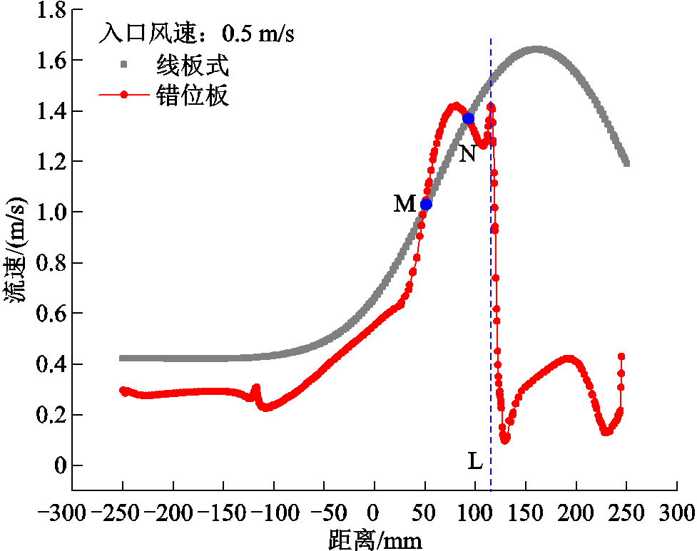
图12 入口风速为0.5 m/s时板前1 cm流速对比
Fig.12 Comparison of flow velocity at 1 cm in front of the plate when the inlet wind speed is 0.5 m/s
图13为入口风速为0.9 m/s时,A、B电极结构板前1 cm流速对比,A、B电极结构整体流速变化趋势与入口风速为0.5 m/s时相似,结构A在x=151 mm处达到峰值1.93 m/s,结构B在x=115 mm处达到峰值1.63 m/s。A、B电极结构平均流速分别为1.28 m/s、0.68 m/s,结构B与结构A相比下降了46.88%,且结构B板前流速均小于结构A。这表明随着入口风速增加,错位极板对气流的影响越加明显,降低二次扬尘的作用也越加明显。
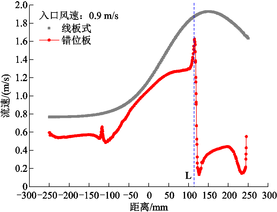
图13 入口风速为0.9 m/s时板前1 cm流速对比
Fig.13 Comparison of flow velocity at 1 cm in front of the plate when the inlet wind speed is 0.9 m/s
本文同时通过实验方法研究了两种结构电除尘器的流场特性。实验以艾烟作为气流状态的示踪粒子,实验风速设置为0.1 m/s。图14和图15分别为不同电压下结构A、结构B的流场分布。图中绿色箭头为局部烟雾流场运动矢量,利用Matlab的互相关算法拟合出的区域流场运动矢量以黄色箭头表示。

图14 不同电压下结构A流场分布
Fig.14 Structure A flow field distribution at different voltages

图15 不同电压下结构B流场分布
Fig.15 Structure B flow field distribution at different voltages
图14为不同电压下结构A流场状态与运动分析图,可见由放电极产生的高速离子射流明显改变了原有流场的状态。由图14b、图14d、图14f和图14h可知,电压增大,放电极因电晕放电产生的离子风速度明显增大,高速离子射流对流场的扰动明显增强,矢量箭头朝向变化幅度增大,涡旋面积也逐渐增大。当电压升至50 kV时,由高速离子射流产生的涡旋面积基本占满除尘器腔体。
图15为不同电压下结构B流场状态与运动分析图。当电压为35 kV时,如图15a所示,烟雾运动至T状结构处,对烟雾产生阻挡,部分烟雾返回与主流烟雾交汇形成涡旋。剩余烟雾继续运动,因阴极产生的高速离子射流影响,部分烟雾会运动至错位板与后收尘极板之间的区域,一部分烟雾被收尘极板吸附,另一部分则与主流烟雾聚合形成面积较小的一对双螺旋结构。从对应的流场分析图15b中可以看出,在放电极两侧呈现出一对面积较小的涡旋,且烟雾的运动速度较高电压低。增加电压至40 kV,如图15c、图15d所示,呈现出左侧涡旋中心靠近后收尘极板,右侧涡旋中心向下靠近放电极的实验现象。电压为50 kV时,如图15g和图15h所示,电压越大,由放电极产生的高速离子射流对流场影响越大,流场运动越剧烈,进入到错位板与后收尘极板之间的烟雾量越多,烟雾在结构B滞留时间延长,增加了被收尘极板捕集的概率。
由第2节所述,采用高速离子射流耦合电流体场的模拟方法可以比较好地反映线板式除尘器内电势分布和近极板的风速。由于实验设备、除尘器内烟雾均匀程度不同以及测量误差等原因,导致图11、图14和图15的实验结果与模拟数据从定量角度还存在一定差距。但是模拟得到的流场特性与实验结果从定性角度是比较相符的。如图11a和图14d中白色虚线圈所示,线板式结构下,在电极两侧实验与模拟流场分布均呈现出一对双螺旋结构。如图11b和图15d中白色虚线圈所示,错位板结构下,模拟中流场状态呈现出两对涡旋;实验中在相同位置形成两对强度不同的涡旋,且左侧涡旋均贴近上收尘板,右侧涡旋均向下偏移,与模拟相对应。以上结果说明,采用高速离子射流耦合电流体场模型模拟静电除尘器电流体场具有可行性。同时实验结果也进一步证明了利用错位板式收尘极设计具有进一步提高收尘效率的可行性。
本文基于COMSOL软件采用高速离子射流耦合电流体场的模拟方法,模拟了两种电除尘器的电势、空间电荷密度分布,以及电流体场和近板流速分布,并结合实验研究了两种电除尘器的电流体场状态。主要得出以下结论:
1)空间电荷密度分布和电场强度分布均与收集板的结构相关,错位板结构空间电荷密度和电场强度较线板结构均有一定提升。
2)错位板结构可以增大颗粒在除尘器内的滞留时间,削弱了离子风对极板的冲刷,降低了二次扬尘现象,从而提高了对粒子的捕集效率。
3)实验结果与使用高速离子射流耦合电流体场模拟方法构建的1:1模型得到的模拟数据相符,验证了此模拟方法的可行性。
参考文献
[1] 刘学军, 胡汉芳, 郦建国, 等. 2020年电除尘行业发展评述和展望[J]. 中国环保产业, 2021(3): 23-27.
Liu Xuejun, Hu Hanfang, Li Jianguo, et al. Review and prospect of the development of electric precipitation industry in 2020[J]. China Environmental Protection Industry, 2021(3): 23-27.
[2] 翟美丹, 米俊锋, 马文鑫, 等. 静电除尘技术及其影响因素的发展现状[J]. 应用化工, 2021, 50(9): 2572-2577.
Zhai Meidan, Mi Junfeng, Ma Wenxin, et al. The development of electrostatic dust removal technology and its influencing factors[J]. Applied Chemical Industry, 2021, 50(9): 2572-2577.
[3] 张明, 李丁晨, 李传, 等. 离子风的应用研究进展[J]. 电工技术学报, 2021, 36(13): 2749-2766.
Zhang Ming, Li Dingchen, Li Chuan, et al. Research progress in the application of ion wind[J]. Transactions of China Electrotechnical Society, 2021, 36(13): 2749-2766.
[4] 庞海龙, 俞妍, 董中天, 等. 静电除尘效率的影响因素研究[J]. 高压电器, 2021, 57(9): 125-130.
Pang Hailong, Yu Yan, Dong Zhongtian, et al. Study on the influence factors of efficiency of electrostatic precipitation[J]. High Voltage Apparatus, 2021, 57(9): 125-130.
[5] 闫东杰, 张子昂, 李振强, 等. 基于PIV的电除尘器流场可视化实验研究进展[J]. 高电压技术, 2021, 47(9): 3325-3336.
Yan Dongjie, Zhang Ziang, Li Zhenqiang, et al. Research progress in flow visualization experiment of electrostatic precipitator based on particle image velocimetry[J]. High Voltage Engineering, 2021, 47(9): 3325-3336.
[6] 申南轩, 苏子寒, 张远航, 等. 湿度对悬浮液滴荷电特性及离子流场特性的影响[J]. 电工技术学报, 2022, 37(13): 3422-3430, 3452.
Shen Nanxuan, Su Zihan, Zhang Yuanhang, et al. Influence of humidity on the charge characteristics of suspension droplets and the characteristics of ion flow field[J]. Transactions of China Electrotechnical Society, 2022, 37(13): 3422-3430, 3452.
[7] 卢斌先, 岳战兵, 王宜静, 等. 椭球电极负电晕放电的数值仿真研究[J]. 电工技术学报, 2023, 38(13): 3379-3387.
Lu Binxian, Yue Zhanbing, Wang Yijing, et al. Numerical simulation study on negative corona discharge of small ellipsoidal electrode[J]. Transactions of China Electrotechnical Society, 2023, 38(13): 3379-3387.
[8] 袁均祥, 杨兰均, 张乔根, 等. 电极参数对尖-板电极空气放电离子风特性的影响[J]. 电工技术学报, 2010, 25(1): 24-29.
Yuan Junxiang, Yang Lanjun, Zhang Qiaogen, et al. Ionic wind characteristic of tine-plat affected by electrode parameter from atmosphere discharge[J]. Transactions of China Electrotechnical Society, 2010, 25(1): 24-29.
[9] Chen Bing, Guo Yongheng, Li Hongjiao, et al. Insights into the effect of the shape of collecting plates on particle precipitation processes in an electrostatic precipitator[J]. Journal of the Air & Waste Management Association, 2020, 70(9): 892-903.
[10] 沈恒, 钟方川, 亢燕铭, 等. 两种实际板型下电除尘器中的电流体动力学流动[J]. 高电压技术, 2017, 43(2): 541-546.
Shen Heng, Zhong Fangchuan, Kang Yanming, et al. Electrohydrodynamic flows in two real electrode geometry of electrostatic precipitator[J]. High Voltage Engineering, 2017, 43(2): 541-546.
[11] Bacher C, Lebedynskyy V, Fischer S, et al. Discharge electrode geometry and energy efficiency in a one-stage wire-tube electrostatic precipitator operating at high concentrations of submicron liquid aerosol[J]. Environmental Technology, 2020, 41(16): 2096-2108.
[12] 邓杰文, 李少华. 多场作用下电除尘器内电动流体运动特性分析[J]. 中国电机工程学报, 2018, 38(8): 2358-2366, 2545.
Deng Jiewen, Li Shaohua. Study of electrofluid motion characteristics under the multi-field in electrostatic precipitator[J]. Proceedings of the CSEE, 2018, 38(8): 2358-2366, 2545.
[13] Zheng Chenghang, Wu Zhicheng, Shen Zhiyang, et al. Particle capture in a high-temperature electrostatic precipitator with different electrode configurations[J]. Powder Technology, 2020, 372: 84-93.
[14] Leonard G L, Mitchner M, Self S A. An experimental study of the electrohydrodynamic flow in electrostatic precipitators[J]. Journal of Fluid Mechanics, 1983, 127: 123-140.
[15] Guo Jun, Ye Xinglian, Wang Shuai, et al. The influence of electrohydrodynamic secondary flow on the collection efficiency and deposition pattern in ESP[J]. Mathematical Problems in Engineering, 2019, 2019: 1-7.
[16] 沈欣军, 曾宇翾, 郑钦臻, 等. 基于粒子成像测速法的正、负电晕放电下线-板式电除尘器内流场测试[J]. 高电压技术, 2014, 40(9): 2757-2763.
Shen Xinjun, Zeng Yuxuan, Zheng Qinzhen, et al. Measurements of flow field in wire-plate electrostatic precipitator during positive or negative corona discharge using PIV method[J]. High Voltage Engineering, 2014, 40(9): 2757-2763.
[17] Choi H Y, Park Y G, Ha M Y. Numerical simulation of the wavy collecting plate effects on the performance of an electrostatic precipitator[J]. Powder Technology, 2021, 382: 232-243.
[18] 闫东杰, 贡浩, 张子昂, 等. 芒刺线-板式电除尘器内流场研究[J]. 中国电机工程学报, 2021, 41(19): 6707-6716.
Yan Dongjie, Gong Hao, Zhang Ziang, et al. Study on the flow field of barb corona electrodes in ESP[J]. Proceedings of the CSEE, 2021, 41(19): 6707-6716.
[19] 李庆, 侯雪超, 张文婷, 等. 电极结构对离子风流场影响的数值模拟[J]. 高电压技术, 2020, 46(12): 4334-4340.
Li Qing, Hou Xuechao, Zhang Wenting, et al. Numerical simulation of influence of electrode structures on ion wind flow field[J]. High Voltage Engineering, 2020, 46(12): 4334-4340.
[20] Feng Zhuangbo, Long Zhengwei, Adamiak K. Numerical simulation of electrohydrodynamic flow and vortex analysis in electrostatic precipitators[J]. IEEE Transactions on Dielectrics and Electrical Insulation, 2018, 25(2): 404-412.
[21] Talaie M R. Mathematical modeling of wire-duct single-stage electrostatic precipitators[J]. Journal of Hazardous Materials, 2005, 124(1/2/3): 44-52.
[22] 龙正伟, 冯壮波, 姚强. 静电除尘器数值模拟[J]. 化工学报, 2012, 63(11): 3393-3401.
Long Zhengwei, Feng Zhuangbo, Yao Qiang. Numerical modeling of electrostatic precipitator[J]. CIESC Journal, 2012, 63(11): 3393-3401.
[23] 李庆, 杨振亚, 王巧艳, 等. 线板放电电流体的实验研究与数值模拟[J]. 科学通报, 2011, 56(35): 2947-2951.
Li Qing, Yang Zhenya, Wang Qiaoyan, et al. Experimental research and numerical simulation of electro-hydrodynamic in wire-plate discharge channel[J]. Chinese Science Bulletin, 2011, 56(35): 2947-2951.
[24] 李庆, 李海凤, 孙晓荣, 等. 电晕放电电流体状态实验研究与数值模拟[J]. 高电压技术, 2010, 36(11): 2739-2744.
Li Qing, Li Haifeng, Sun Xiaorong, et al. Experimental research and numerical simulation of electro-hydrodynamic in corona discharge[J]. High Voltage Engineering, 2010, 36(11): 2739-2744.
[25] 李庆, 刘晓娃, 剧晓晨, 等. 针-板电极负电晕放电下离子分布状态的影响因素[J]. 高电压技术, 2017, 43(5): 1700-1706.
Li Qing, Liu Xiaowa, Ju Xiaochen, et al. Influencing factors of the ions distribution under the needle to plate negative corona discharge[J]. High Voltage Engineering, 2017, 43(5): 1700-1706.
[26] Penney G W, Matick R E. Potentials in D-C corona fields[J]. Transactions of the American Institute of Electrical Engineers, Part I: Communication and Electronics, 1960, 79(2): 91-99.
[27] de Oliveira A E, Guerra V G. Influence of particle concentration and residence time on the efficiency of nanoparticulate collection by electrostatic precipitation[J].Journal of Electrostatics, 2018, 96: 1-9.
Abstract In electrostatic precipitators, changes in electrode structure can affect the distribution of flow fields, which are crucial for particle motion. In order to further improve the dust removal efficiency of electrostatic precipitators, this paper proposes a electrohydraulic field electrode structure. The influence of electrode structure on the electric field characteristics and electrohydraulic field inside the electrostatic precipitator is simulated and experimented and uses a combination of numerical simulation and experimental methods to study. This paper first establishes a numerical model using the simulation method of high-speed ion jet coupled electrohydraulic field. In this model, it assumes an initial wind speed in the electrohydraulic field control equations and only considers the area 1 mm around the discharge electrode as a high-speed ion jet source when studying the electrohydraulic field state. The perturbation of the electrohydraulic field caused by the ionic wind jet is then fit using a two-way coupling between the newly added high-speed ion jet source and the electrohydraulic field equations. The initial jet wind speed surrounding the discharge electrode is setted at 5.76 m/s, 10.82 m/s, 15.68 m/s, and 19.53 m/s when the voltage is 35 kV, 40 kV, 45 kV, and 50 kV, respectively, based on the actual wind speed measured in the experiment. The paper simultaneously used particle image velocimetry to measure the electrohydraulic state of two electrode structures at different voltages. The smoke with the main airflow flows directly to the camera shooting area, so that the laser source and the shooting surface perpendicular to use camera software to save photos, post-processing using Matlab software in the PIV module for the electrohydraulic field state analysis.
Simulation and experimental results show that, the dislocation plate's space charge density is greater than that of the wire-plate type. At the T-shaped structure, the dislocation plate's electric field strength is four times greater than that of the wire-plate type. The corona currents of the dislocation plate and the wire-plate type structure are 12.8 μA and 6.7 μA, respectively, which are each 6.1 μA more than that of the wire-plate type. The average flow velocities of 1 cm in front of the dust collector plate at an intake wind speed of 0.9 m/s are 1.28 m/s for the wire-plate dust collector and 0.68 m/s for the dislocation plate dust collector. Likewise, as inlet wind speed rises, the effect of the dislocation plate's reduction in near-plate flow velocity also becomes increasingly clear. The electrohydraulic field distributions obtained from experiment and simulation are fairly similar when comparing the electrohydraulic field states at 40 kV for the dislocation plate and the wire-plate type voltages, respectively.
The main conclusions of this paper are: (1) The dislocation plate type can increase the space charge density, electric field strength, and corona discharge strength in comparison to the wire-plate type. (2) From the standpoint of the electrohydraulic field, the dislocation plate arrangement can lengthen the duration that particles are retained in the dust collector and reduce the ionic wind's tendency to scrub the pole plate. (3) The high-speed ion jet linked electrohydraulic field simulation method yielded simulation data that was compatible with the experimental findings, demonstrating the technology's viability.
keywords:Electrohydraulic field, dislocation plate, ionnic wind, numerical simulation, particle image velocimetry
中图分类号:X513;TM12
DOI: 10.19595/j.cnki.1000-6753.tces.230919
国家自然科学基金项目(U23A20678)、河北省自然科学基金项目(E2022201057, E2021201037)和河北大学大学生创新创业训练项目(2023122)资助。
收稿日期 2023-06-14
改稿日期 2023-07-27
李 庆 男,1968年生,研究员,博士生导师,研究方向为气体放电、大气污染治理。
E-mail:liqinghbu@126.com(通信作者)
郭朋朋 男,1999年生,硕士研究生,研究方向为大气污染监测与控制。
E-mail:1340048840@qq.com
(编辑 李 冰)