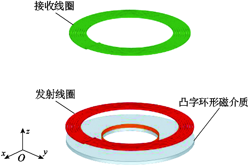
图1 带凸字环形有界磁屏蔽圆形线圈三维示意图
Fig.1 3-dimensional view of finite magnetically shielded circular coil with convex ring type
摘要 互感是无线电能传输系统中的重要参数之一,精确计算互感可为无线电能传输设计及优化提供理论依据,然而目前带凸字环形有界磁屏蔽任意位置圆形线圈互感计算问题还未解决。该文提出空间边界矢量解析法对互感进行精确求解。此方法通过边界条件求解各区域磁矢势,利用空间矢量坐标变换法,结合诺依曼公式得到任意位置互感计算表达式。通过仿真和实验对所提公式的有效性进行验证,互感计算值和实验值之间误差最大为2.86%。互感计算值、仿真值和实验值吻合良好,验证了所提计算方法的正确性。该文所提模型结构,可为水下供电提供更灵活的布局,且在同等规格下,该模型结构相比传统圆盘形结构节省19.6%的材料,其除高角度偏转外互感可达到圆盘形互感的99%。
关键词:无线电能传输 环形磁屏蔽 圆形线圈 互感计算
近年来,无线电能传输(Wireless Power Transfer, WPT)技术逐渐兴起,该技术可实现无接触式电能传输,相比传统有线电能传输模式,其具有更加灵活、便携、安全的特性。目前该技术已广泛应用于电动汽车、便携式电子设备、生物医疗、水下供电等领域[1-7]。在WPT系统设计和结构优化过程中,互感是决定WPT系统传输效率的关键参数之一,如何快速、准确地计算互感是该过程的关键步骤,而在实际应用中,为适用不同的应用场景,WPT系统结构也不尽相同,并且传输系统线圈间相对位置改变也会导致互感发生变化,从而影响传输效率。因此,研究WPT系统中线圈在不同相对位置下的互感计算方法具有重要意义。
目前广泛应用的结构有矩形线圈与圆形线圈,其中对互感计算方法的相关研究已有许多,这些研究工作基于Biot-Savart定律[8]、椭圆积分[9-10]、贝塞尔函数[11]、傅里叶变换[12]以及诺依曼公式[13]等。
关于圆形线圈结构的互感不带磁屏蔽材料相关研究,文献[14]提出了一个基于部分电感方法推导公式,以计算具有任意边数的两个平面螺旋线圈之间的互感,利用n边形平面螺旋线圈对圆形平面螺旋线圈近似表示。文献[15]利用诺依曼公式和磁耦合WPT等效模型计算同轴线圈互感。文献[16]提出了一种基于磁矢量电位分析方法求解同轴不同线圈间互感。文献[17]利用磁矢势求解水平偏移圆形线圈之间的互感公式。文献[18-19]提出了一种基于诺依曼公式的任意空间位置圆形线圈间互感改进算法。文献[20]利用欧拉角,提出了对平面螺旋线圈在任意相对位置下的互感精确表达。文献[21-22]基于Biot-Savart定律,可以计算空间磁通密度,并通过错位变化的数值积分计算圆形线圈间任意位置的互感。
实际应用中为使WPT系统更稳定、更抗干扰,往往会在系统结构中加入磁屏蔽材料。而带磁屏蔽材料的相关研究还很有限。文献[23]提出一种基于场路耦合的计算方法,计算了同轴带磁屏蔽材料圆形线圈间的互感。文献[24]基于傅里叶-贝塞尔变换和双傅里叶变换,建立了两个半无限磁屏蔽材料圆形平面螺旋线圈之间水平偏移的互感解析模型。文献[25]提出了一种基于截断区域特征函数展开法对带有界磁屏蔽圆形线圈间水平偏移的互感计算方法。文献[26]基于坐标变换法和电场强度,得到了带半无界双层屏蔽上任意相对位置的两个圆形线圈之间互感的解析公式。但该方法磁屏蔽材料尺寸为无限大,与实际应用不符。文献[27]通过麦克斯韦方程组求解双层有界圆形磁屏蔽圆形线圈任意位置的互感计算。该方法虽对有界磁屏蔽材料模型进行求解,但未对材料节省方面做出考虑。文献[28]对环形磁屏蔽材料的屏蔽性能进行了验证,在同等规格下环形磁屏蔽材料与圆盘形磁屏蔽材料的屏蔽性能相近。
综上所述,目前带环形有界磁屏蔽材料任意位置圆形线圈间的互感计算还需进一步研究。因此,本文建立带凸字环形有界磁屏蔽任意位置圆形线圈互感计算模型,如图1所示。
图1 带凸字环形有界磁屏蔽圆形线圈三维示意图
Fig.1 3-dimensional view of finite magnetically shielded circular coil with convex ring type
本文通过空间边界矢量解析法得到带凸字环形有界磁屏蔽任意位置圆形线圈互感快速计算表达式。最后,通过仿真和实验对所提计算方法的正确性、有效性进行验证。在同等规格下,此结构除高角度偏转以外,其互感可达到圆盘形磁屏蔽材料传输结构互感的99%,同时磁屏蔽材料节省了19.6%。
本文互感计算流程共分为五步,如图2所示。
为实现与圆盘形磁屏蔽材料相近的磁屏蔽性能,优化传输结构模型,将沿环形磁屏蔽材料内环增加内沿薄壁,建立带环形磁屏蔽圆形平面螺旋线圈轴对称结构,如图3所示。根据空间边界矢量解析法,将该模型依次由z=z1、z=0、z=-d1和z=-d2划分为五个区域。其中,c1为环形磁屏蔽材料的内径,c2为环形磁屏蔽材料内环增加内沿薄壁的外径,c3为环形磁屏蔽材料的外径。d1与d2分别为内沿薄壁与整个磁屏蔽材料的高度。μ1与σ分别为磁屏蔽材料的磁导率与电导率。r1与r2分别为发射线圈与接收线圈的半径。z1和z2分别为发射线圈和接收线圈与磁屏蔽材料的垂直高度,Δz为发射线圈与接收线圈圆心间的垂直距离。h为磁矢势的截断距离。发射线圈由稳态电流Iejωt激励,其中,I为电流幅值,ω为角频率,t为时间变化量。
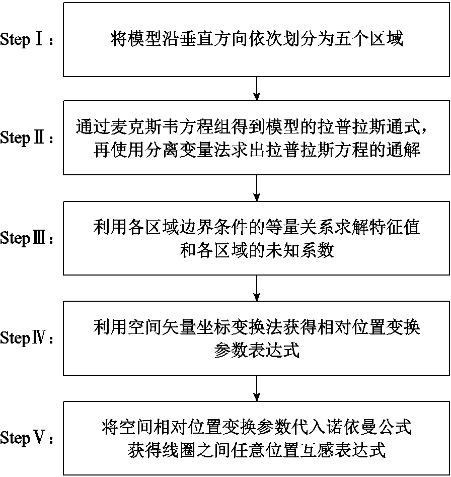
图2 任意位置互感计算流程
Fig.2 Arbitrary position mutual sense calculation flow
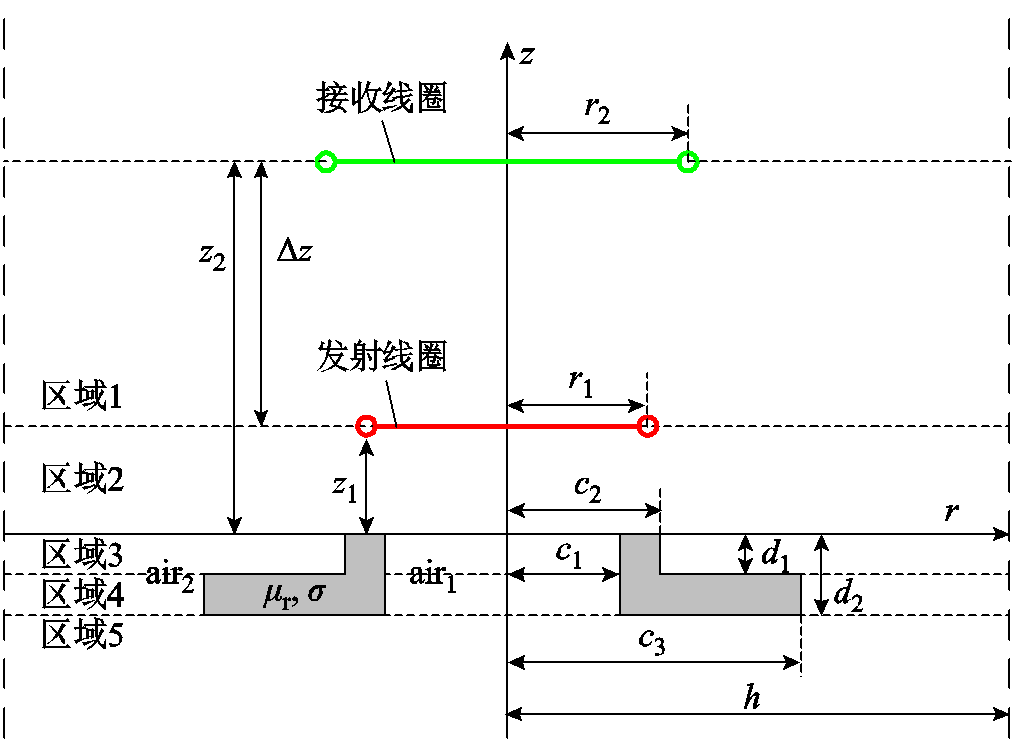
图3 带凸字环形磁屏蔽圆形螺旋线圈横截面
Fig.3 Circular spiral coil cross-section with convex ring type magnetic shield
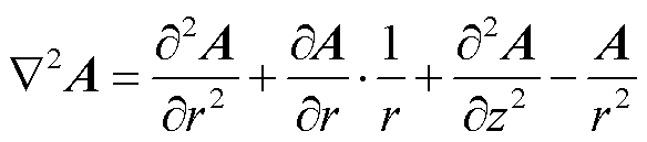
为方便计算,建立圆柱坐标系(r, φ, z),引入洛伦兹规范的磁矢势A,由于在圆柱对称模型中,磁矢势A只有周向分量,故有A=Aφ。通过麦克斯韦方程组可以得到含有磁矢势A的拉普拉斯方程满足
 (1)
(1)
式中, 为拉普拉斯算子。通过分离变量法对式(1)求解得到磁矢势A(r, z)含有贝塞尔函数的通解为
![]() (2)
(2)
式中,As、Bs、Cs、Ds为区域s边界条件系数;s为区域序号;i为级数的项数; 为区域i特征值,且满足
 ,其中,μ0为真空磁导率;J1(ξir)和Y1(ξir)分别为一阶贝塞尔函数和一阶诺依曼函数。
由于所求磁矢势A应为有限值,而Y1(ξir)在原点r=0时发散,故在区域1、2、5时Bs=0,此区域当作真空区域,取 =0,因此对应区域磁矢势A(r, z)可以表示为
式中,特征值ξ可通过r=h时磁矢势A=0这一边界条件求解。由于式(3)~式(5)中,指数部分不为0,故存在J1(ξih)=0,使得磁矢势A=0,进而求出特征值ξ。区域3与区域4如图3所示,以c1、c2与c1、c3可分为三个子区域,分别为air1、铁氧体fer和air2。通过子区域边界条件和贝塞尔函数敛散性可以得到
式中, 和
和 为区域特征值,且满足
 。
。
为化简表达式,令
 (12)
(12)
式中, 、
、 和
和 、
、 分别为k阶贝赛尔函数和诺依曼函数。与求解特征值ξ同理,特征值与可通过Rq1(qih)=0与Qq1(qih)=0进行求解。
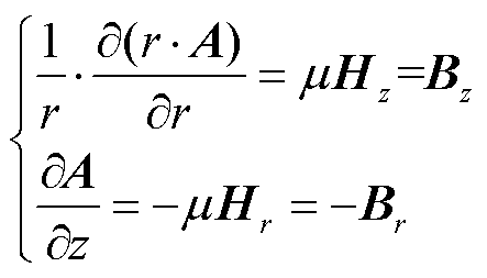
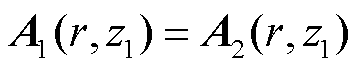
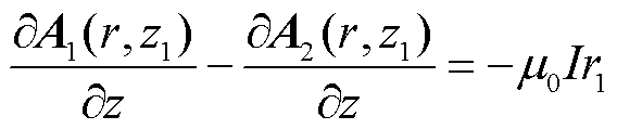
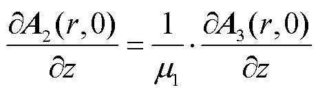
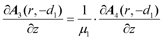
由电磁场基本原理Ñ´A=mH可得边界条件
 (13)
(13)
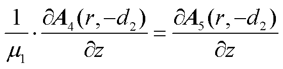
式中, 为磁导率;B和H分别为磁感应强度与磁场强度,下标z与r分别表示法向和切向分量。故存在
 和
和 ,联立方程可得
 (14)
(14)
 (15)
(15)
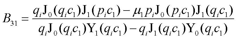
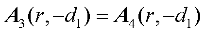
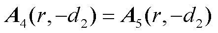
与求解式(14)、式(15)方法一致,利用边界条件式(13)可对A32、B32、A41、B41、A42、B42求解。同时,亦可根据边界条件得到
 (16)
(16)
 (17)
(17)
 (18)
(18)
 (19)
(19)
 (20)
(20)
 (21)
(21)
 (22)
(22)
 (23)
(23)
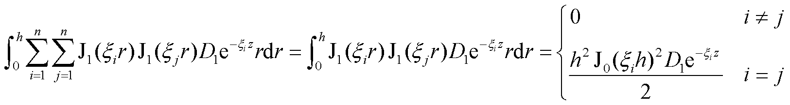
所求磁矢势A虽然为无穷级数,但由于包含贝塞尔函数使其快速收敛,故求解有限项即可得到逼近的结果。
以式(3)为例,取i为有限项n,两边同时乘以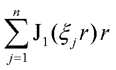 ,对r从0→h进行积分,再利用贝塞尔函数正交性,则有
 (24)
(24)
将此方法运用至式(16)~式(23)中则有
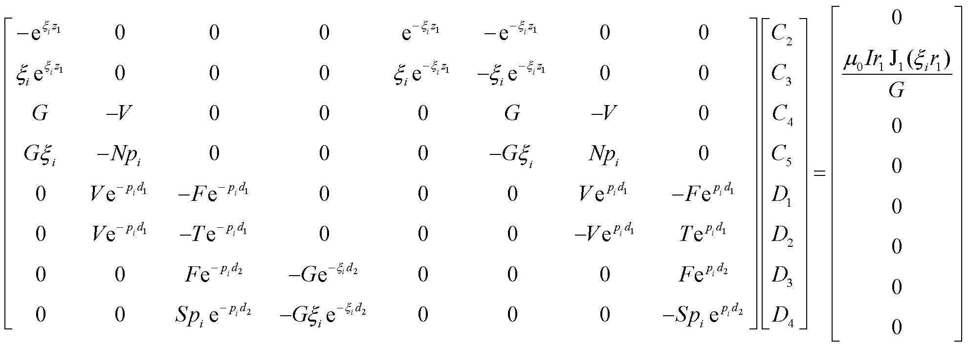 (25)
(25)
式中,C2、C3、C4、C5、D1、D2、D3、D4可使用符号运算或克莱姆法则等进行计算;G、V、N、F、S、T为中间变量,分别为
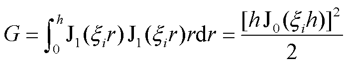 (26)
(26)
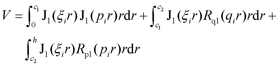 (27)
(27)
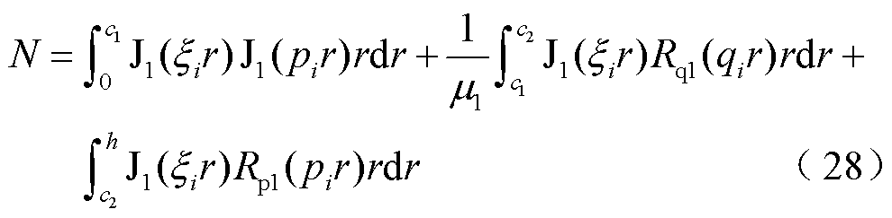
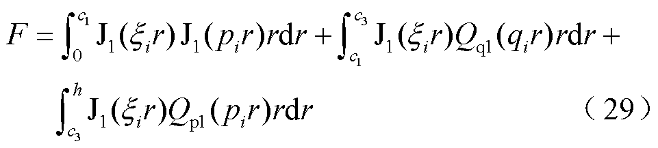
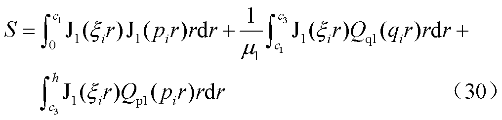
式中, 、
、 、
、 、
、 分别为式(12)贝赛尔函数和诺依曼函数阶数k=1时的结果;J0表示0阶贝赛尔函数。
建立带双环形磁屏蔽圆形线圈任意相对位置计算系统框图,如图4所示。接收线圈绕yc轴逆时针偏转角δy,沿xc轴负方向偏移x,圆O以E2为圆心交接收线圈于W,连接E2W为圆O半径r(θ)。dl和Ao分别为接收线圈和圆O在点W上切线,其夹角为λ,其中dl为接收线圈线元,Ao为磁矢势分量。
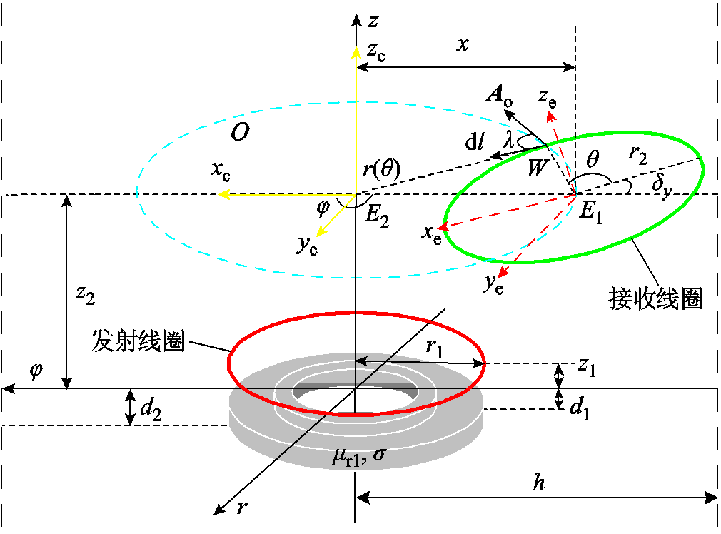
图4 带凸字环形磁屏蔽圆形线圈任意相对位置计算系统示意图
Fig.4 Schematic diagram of the system for calculating the arbitrary relative position of a circular coil with convex ring type magnetic shield
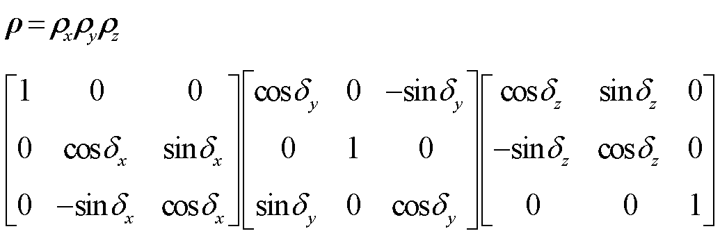
任意位置互感计算首先需计算出空间相对位置变换参数。通过空间矢量坐标变换矩阵
 (32)
(32)
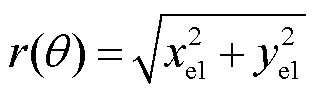
对坐标(xc, yc, zc)进行变换得到(xe, ye, ze),加上偏移坐标位置即可实现任意相对位置的计算。其中接收线圈与圆O参数方程分别为
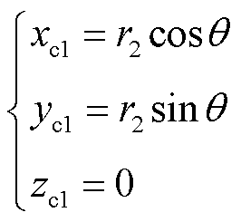 (33)
(33)
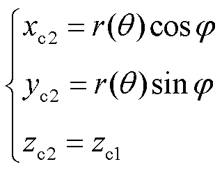 (34)
(34)
此处以偏移加绕yc逆时针偏转为例,得到接收线圈相对位置改变后参数方程
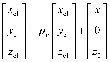 (35)
(35)
式中, 为空间矢量变换矩阵中y方向的变换矩阵。
由几何关系可知
 (36)
(36)
对式(35)和式(34)分别对θ与φ求导,得到接收线圈与圆O交点W切向量为
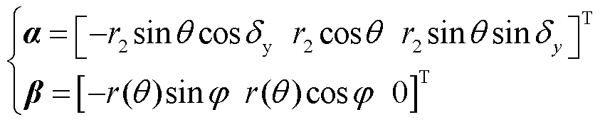 (37)
(37)
其中,关于φ变量的三角函数,可利用其相交于一点的特性,将式(33)和式(34)联立,即可求出仅含θ与δy的结果。
最后,通过式(36)求出空间相对位置变换余弦参数
 (38)
(38)
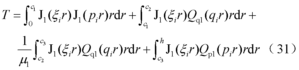
由于所求互感需要得到发射线圈与接收线圈间磁通量,故仅需求出式(3),则得到磁通量为
 (39)
(39)
式中,l为线圈积分路径,结合所求余弦参数式(37),利用几何关系对dl进行替换,则有单匝互感为
 (40)
(40)
通过逐一累加线圈线径改变量,求出不同半径下线圈互感,最后累加得到多匝线圈总互感为
 (41)
(41)
式中,f、g分别代表发射线圈与接收线圈计算至第几匝处;T1、T2分别为发射线圈与接收线圈总匝数。
为验证所提式(41)的有效性,仿真通过Ansys Maxwell建模验证,实验测试装置如图5所示,实验使用LCR测试仪IM3536进行测试,设置电流频率为85 kHz。本节将对线圈相对位置垂直偏移、水平偏移、水平角度偏转和水平偏移加角度偏转四种变化进行验证。其中,磁屏蔽材料和发射线圈位置保持不变,仅改变接收线圈位置。实验模型线圈相对位置变化如图6所示。

图5 实验装置
Fig.5 Experimental setup

图6 实验模型线圈相对位置变化
Fig.6 Experimental model coil relative position change
实验测试原理是将两线圈分别进行同向串联和反向串联,图7所示为实验模型线圈互感测试连接示意图。利用多匝线圈不同方向的连接特性,用同向串联电感减去反向串联电感即可得到4倍总互感Mtotal,再将此结果除以4即可得到收发线圈间互感Mtotal。实验模型参数见表1。
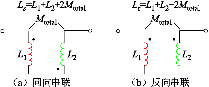
图7 实验模型线圈互感测试连接示意图
Fig.7 Experimental model coil mutual inductance test connection diagram
表1 线圈与磁屏蔽材料参数
Tab.1 Coil and magnetic shielding material parameters
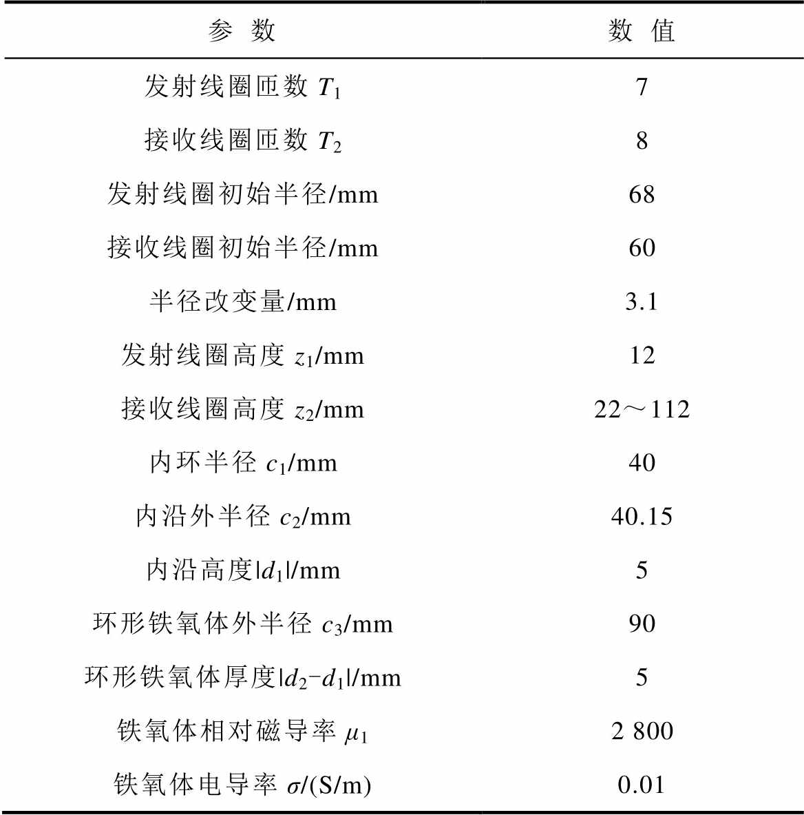
参数数值 发射线圈匝数T17 接收线圈匝数T28 发射线圈初始半径/mm68 接收线圈初始半径/mm60 半径改变量/mm3.1 发射线圈高度z1/mm12 接收线圈高度z2/mm22~112 内环半径c1/mm40 内沿外半径c2/mm40.15 内沿高度|d1|/mm5 环形铁氧体外半径c3/mm90 环形铁氧体厚度|d2-d1|/mm5 铁氧体相对磁导率μ12 800 铁氧体电导率σ/(S/m)0.01
将表1参数代入式(3)输出接收线圈z2=22 mm时,同轴状态下磁矢势A1随r增大的变化曲线如图8a所示,同时输出Ansys Maxwell模型接收线圈z2= 22 mm、r为正方向时磁场分布截面如图8b所示。
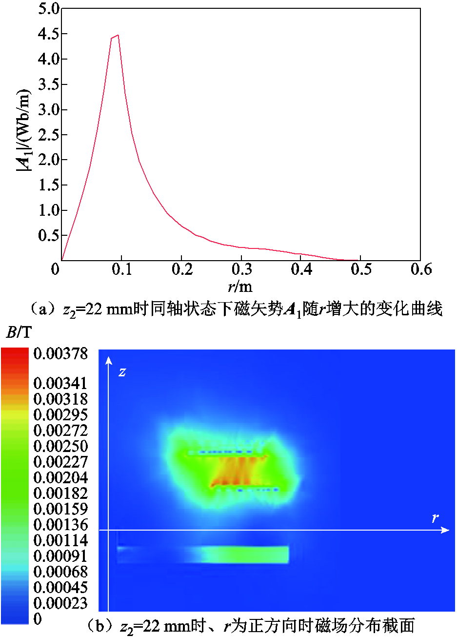
图8 磁矢势A1与磁场分布变化
Fig.8 Variation of magnetic vector potential A1 with magnetic field distribution
分析图8可知,磁矢势A1在r为0~0.1 m,磁矢势逐渐增加,随后逐渐减小,符合该位置磁场分布。
接收线圈垂直偏移实验,设定接收线圈从z2= 22 mm沿z轴正方向以步长为10 mm依次垂直偏移至z2=112 mm,如图9所示。
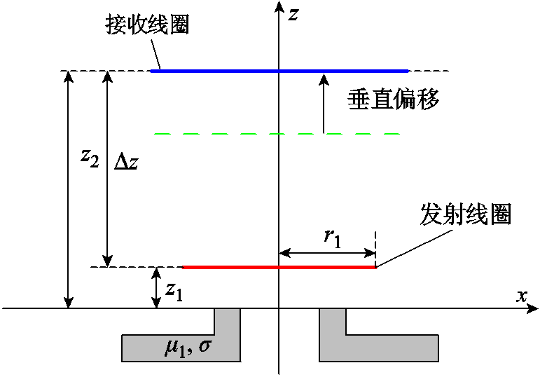
图9 接收线圈垂直偏移示意图
Fig.9 Schematic diagram of vertical offset of receiving coil
图9中,Δz为接收线圈与发射线圈间垂直距离。虚线为接收线圈上一时刻的位置,(蓝色)实线为偏移后的位置。接收线圈垂直偏移所测的互感数据及误差对比见表2。表中,Mtotal为计算互感,Ms为仿真互感,Me为实验互感;ε1为计算互感与仿真互感的误差,ε2为计算互感与实验互感的误差。本文后续含义与此一致。ε1与ε2表达式分别为
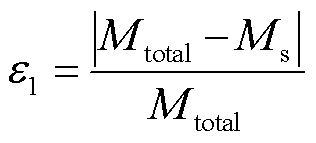 (42)
(42)
表2 垂直偏移时互感及误差
Tab.2 Mutual inductance and error at vertical offset
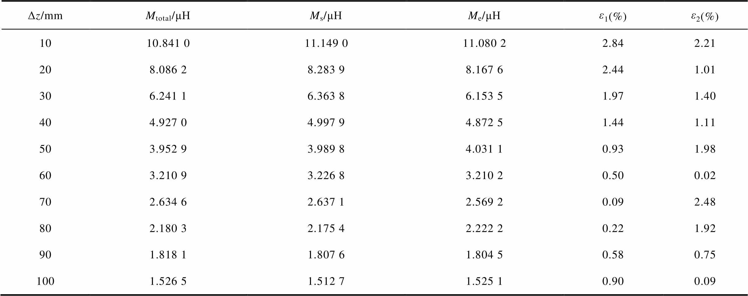
Δz/mmMtotal/μHMs/μHMe/μHε1(%)ε2(%) 1010.841 011.149 011.080 22.842.21 208.086 28.283 98.167 62.441.01 306.241 16.363 86.153 51.971.40 404.927 04.997 94.872 51.441.11 503.952 93.989 84.031 10.931.98 603.210 93.226 83.210 20.500.02 702.634 62.637 12.569 20.092.48 802.180 32.175 42.222 20.221.92 901.818 11.807 61.804 50.580.75 1001.526 51.512 71.525 10.900.09
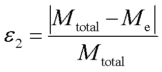 (43)
(43)
分析表2可知,计算互感与仿真互感在发射线圈与接收线圈垂直距离为10~100 mm时误差ε1均不大于2.84%,计算互感与实验互感误差ε2不大于2.48%。计算互感与仿真互感及实验互感结果具有很好的一致性。结合表2,建立计算、仿真及实验的互感随线圈间垂直距离变化曲线如图10所示。
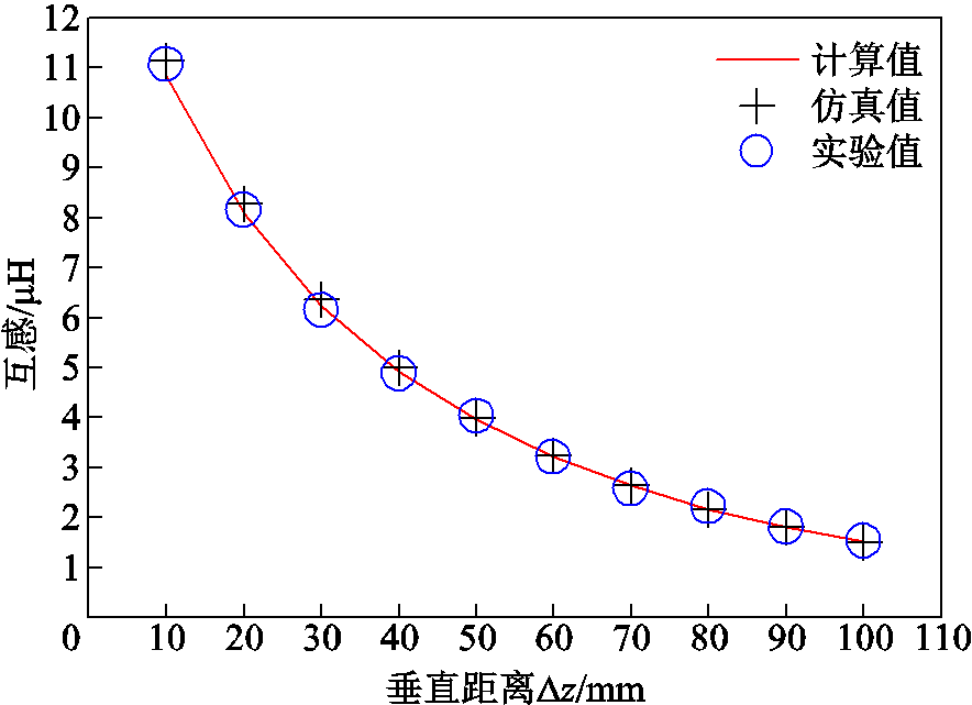
图10 互感随线圈间垂直距离变化曲线
Fig.10 Variation curve of mutual inductance with vertical distance between coils
分析图10可知,互感随着接收线圈与发射线圈间垂直距离的增加逐渐减小,这是由于随着线圈间垂直距离的增加导致线圈间磁通量逐渐降低,因此线圈间互感会逐步下降。
接收线圈水平偏移实验,设定z2=72 mm,其与发射线圈间垂直距离Δz=60 mm。接收线圈在此垂直高度以x=50 mm为起点,以10 mm为步长沿x轴负方向依次水平偏移至x=-50 mm。接收线圈水平偏移示意如图11所示。接收线圈水平偏移所测的互感数据及误差对比见表3。表中x为水平偏移距离,本文后续均为此含义。
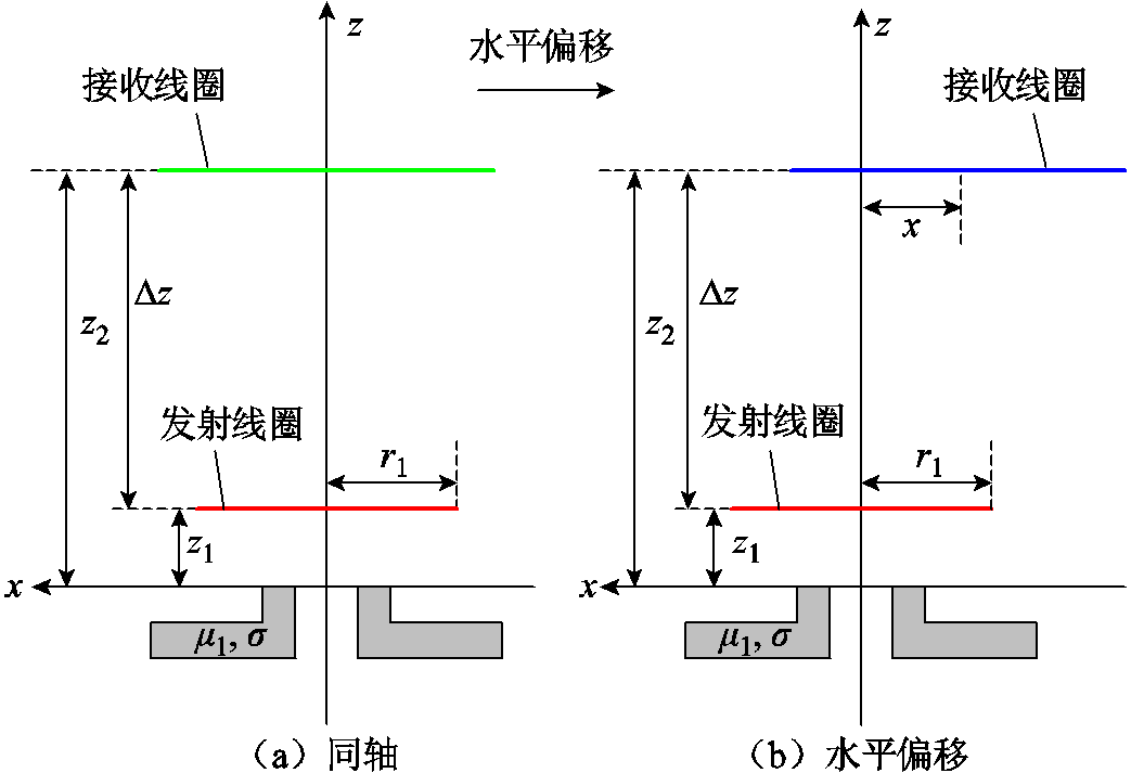
图11 接收线圈水平偏移示意图
Fig.11 Schematic diagram of the horizontal offset of the receiving coil
表3 垂直距离Δz=60 mm时水平偏移互感及误差
Tab.3 Horizontal offset mutual inductance and error at vertical distance Δz=60 mm
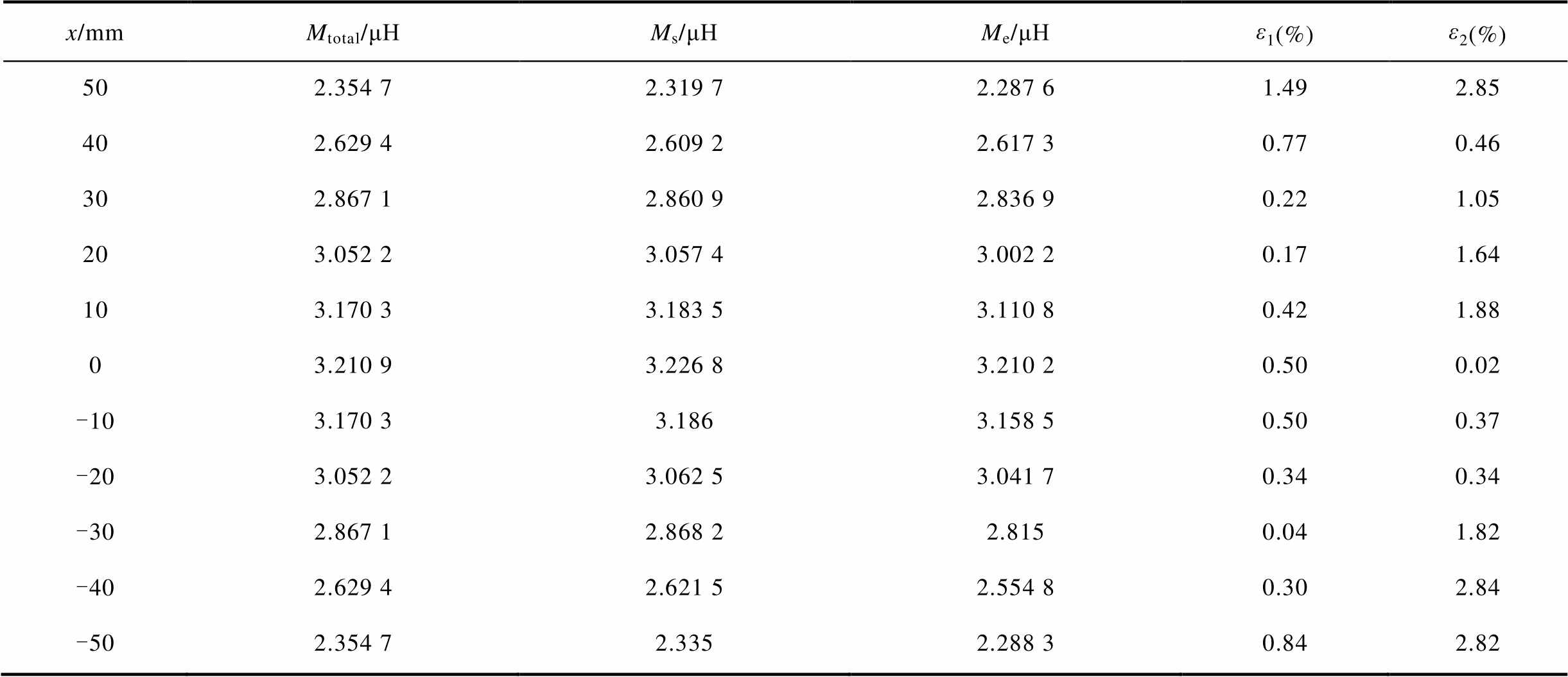
x/mmMtotal/μHMs/μHMe/μHε1(%)ε2(%) 502.354 72.319 72.287 61.492.85 402.629 42.609 22.617 30.770.46 302.867 12.860 92.836 90.221.05 203.052 23.057 43.002 20.171.64 103.170 33.183 53.110 80.421.88 03.210 93.226 83.210 20.500.02 -103.170 33.1863.158 50.500.37 -203.052 23.062 53.041 70.340.34 -302.867 12.868 22.8150.041.82 -402.629 42.621 52.554 80.302.84 -502.354 72.3352.288 30.842.82
分析表3可知,计算互感与仿真互感在接收线圈水平偏移距离除x=50 mm时误差ε1为1.49%外,其余误差均不大于0.84%。计算互感与实验互感误差ε2不大于2.85%。计算互感与仿真互感及实验互感结果具有良好的一致性。结合表3,建立计算、仿真及实验的互感随接收线圈水平偏移变化曲线如图12所示。
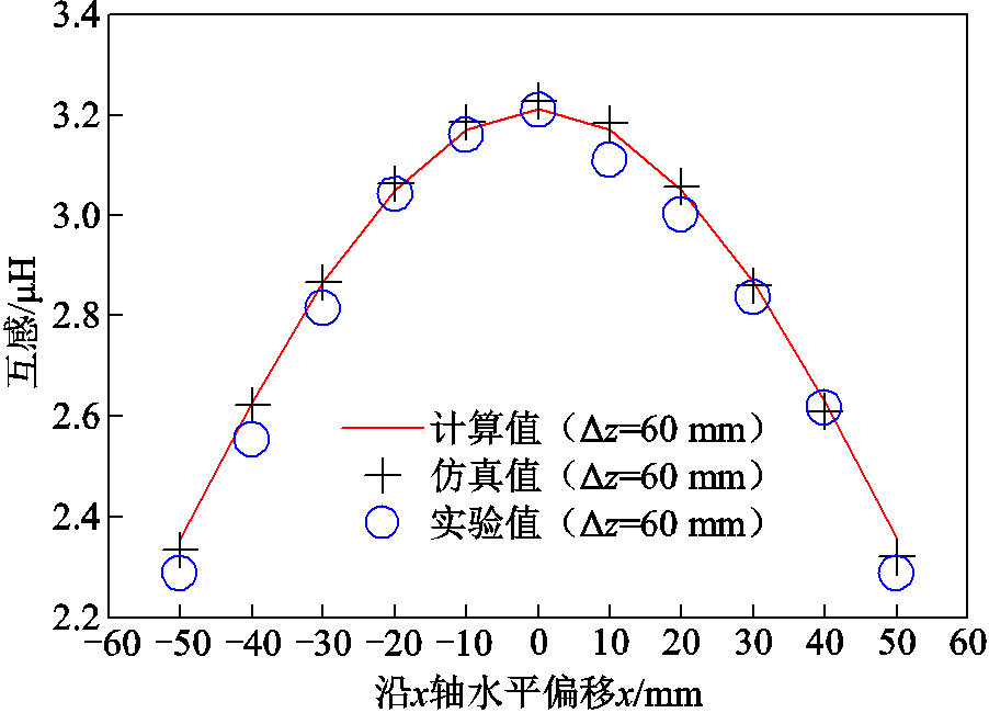
图12 互感随接收线圈水平偏移变化曲线
Fig.12 Variation curve of mutual inductance with horizontal offset of receiving coil
分析图12可知,在垂直高度不变的情况下,沿x轴左右偏移,偏离中心位置越远互感越小。这是由于该结构磁通量是由中间向周围递减,因此随着水平偏移距离逐渐增大互感逐渐下降。
接收线圈水平角度偏转实验,设定z2=102 mm,与发射线圈的垂直距离Δz=90 mm。接收线圈以x轴为偏转轴,逆时针偏转δx,以0°为起点,步长为10°依次偏转至90°,如图13所示。接收线圈水平角度偏转所测的互感数据及误差对比见表4。
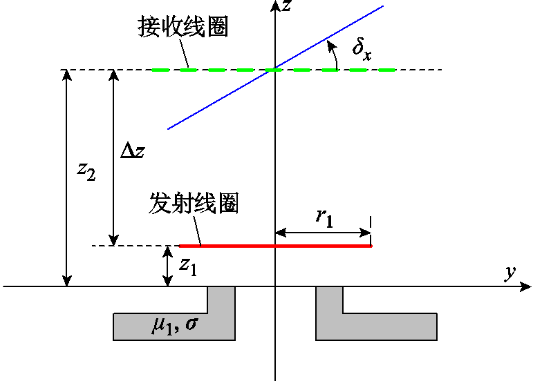
图13 接收线圈水平角度偏转示意图
Fig.13 Schematic diagram of horizontal angle deflection of receiving coil
表4 垂直距离Δz=90 mm时水平角度偏转互感及误差
Tab.4 Horizontal angular deflection mutual inductance and error at vertical distance Δz=90 mm
δx/(°)Mtotal/μHMs/μHMe/μHε1(%)ε2(%) 01.818 11.807 61.804 50.580.75 101.827 61.823 91.831 70.200.22 201.852 91.857 91.825 80.271.46 301.880 51.897 61.903 10.911.20 401.876 51.907 91.930 21.672.86 501.774 31.818 21.756 92.470.98 601.507 61.556 71.506 83.260.05 701.0831.115 41.081 22.990.17 800.561 660.561 460.562 60.040.17 9000.039 067
分析表4可知,计算互感与仿真互感在接收线圈水平偏转0°~80°时误差ε1不大于3.26%,计算互感与实验互感误差不大于2.86%。由于角度偏转至90°时没有实际意义,故此处不作对比,仿真互感在此处具有较小数值是由于在仿真建模接口处存在不可避免的微小突起,偏转至此处时有微小磁通量,故存在此数据。计算互感与仿真互感及实验互感结果基本一致。结合表4,建立计算、仿真及实验互感随接收线圈水平偏转变化曲线如图14所示。
分析图14可知,互感在接收线圈水平角度偏转0°~40°时有微小的增加的趋势,这是由于接收线圈并非标准的圆形,接收线圈沿逆时针方向缠绕,线圈以x轴为分界线,左侧线圈外径会略大于右侧线圈外径,发生逆时针偏转时左侧线圈更接近于发射线圈,且接收线圈向xOy面投影落入发射线圈覆盖的位置略微变大,导致磁通量略微增大,故有此现象。同时,可以看到水平偏转角度在0°~50°内互感未出现大幅度下降,在60°~70°时出现明显下降,这是由于偏转角度大于60°时,接收线圈向xOy面的投影基本落在发射线圈内径内,间接地使发射线圈与接收线圈发生错位,因此互感逐渐下降。
图14 互感随接收线圈水平偏转变化曲线
Fig.14 Variation curve of mutual inductance with horizontal deflection of receiving coil
接收线圈水平偏移加角度偏转实验,设定 z2=72 mm,与发射线圈的垂直距离Δz=60 mm。以y轴为旋转轴逆时针旋转20°,以x=50 mm为起点步长为10 mm,向x轴负半轴依次水平偏移至x= -50 mm。如图15所示。接收线圈在水平角度偏转下水平偏移所测的互感数据及误差对比见表5。
图15 接收线圈水平偏移加角度偏转示意图
Fig.15 Schematic diagram of horizontal offset plus angular deflection of the receiving coil
分析表5可知,计算互感与仿真互感在接收线圈水平偏移50~-50 mm内误差ε1不大于1.84%。计算互感与实验互感误差ε2不大于2.47%。计算互感与仿真互感及实验互感结果有较好的一致性。结合表5,建立计算、仿真及实验的互感水平角度偏转下随接收线圈水平偏移变化曲线如图16所示。
表5 垂直距离Δz=60 mm,水平角度偏转δy=20°时水平偏移互感及误差
Tab.5 Vertical distance Δz=60 mm, horizontal deflection δy=20° when horizontal deflection mutual sense and error
x/mmMtotal/μHMs/μHMe/μHε1(%)ε2(%) 502.413 32.368 92.402 51.840.45 402.717 22.688 62.745 61.051.05 302.990 72.981 63.010 40.300.66 203.205 83.2143.198 70.260.22 103.333 43.359 8 3.292 50.791.23 03.354 33.394 53.332 1.200.66 -103.268 63.314 73.3391.412.15 -203.093 33.138 63.092 31.460.03 -302.852 22.892 82.781 71.422.47 -402.565 92.591 52.513 11.002.06 -502.249 52.2572.273 10.331.05
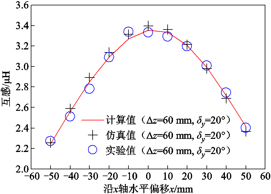
图16 互感在水平角度偏转下随接收线圈水平偏移变化曲线
Fig.16 Variation curve of mutual inductance with horizontal deflection of receiving coil under horizontal angular deflection
分析图16可知,互感以x轴0点为中心向其正负半轴水平偏移时互感逐步下降,且可以看到向x轴正半轴水平偏移比向x轴负半轴水平偏移时互感下降的趋势慢,这是由于所设为接收线圈以y轴为旋转轴逆时针旋转20°,在x轴水平偏移至正半轴时磁通量略大于水平偏移至负半轴的磁通量,故有此现象。
将本文所提计算模型利用Matlab编写程序与Ansys Maxwell仿真软件进行速度对比,除去使用Ansys Maxwell建模的时间,在同一计算机硬件配置下,分别使用Matlab计算和Ansys Maxwell仿真相同参数带凸字环形有界磁屏蔽圆形线圈互感模型,对比求解互感的速度见表6。表中,tc为测试所耗时间,t1为Ansys Maxwell仿真所耗平均时间,t2为Matlab所耗平均时间。Ma表示垂直偏移状态下,Mb表示水平偏移状态下,Mc表示水平角度偏转状态下,Md表示水平偏移加角度偏转状态下。
表6 计算互感所耗时间
Tab.6 Time taken to calculate mutual inductance
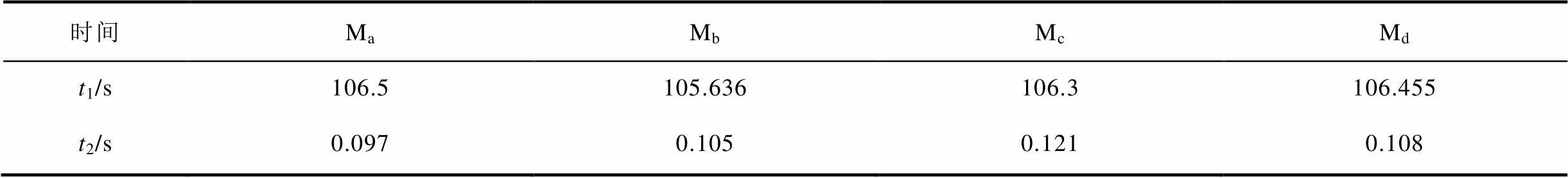
时间MaMbMcMd t1/s106.5105.636106.3106.455 t2/s0.0970.1050.1210.108
分析表6可知,Ansys Maxwell仿真最短平均用时为105.636 s,而使用本文所提方法编写的Matlab程序最长平均所用时间为0.121 s,远快于Ansys Maxwell仿真时间,故本文所提方法在计算速度上优势显著。对本文所提计算方法与文献中的方法进行对比见表7。
表7 计算方法对比
Tab.7 Comparison of calculation methods
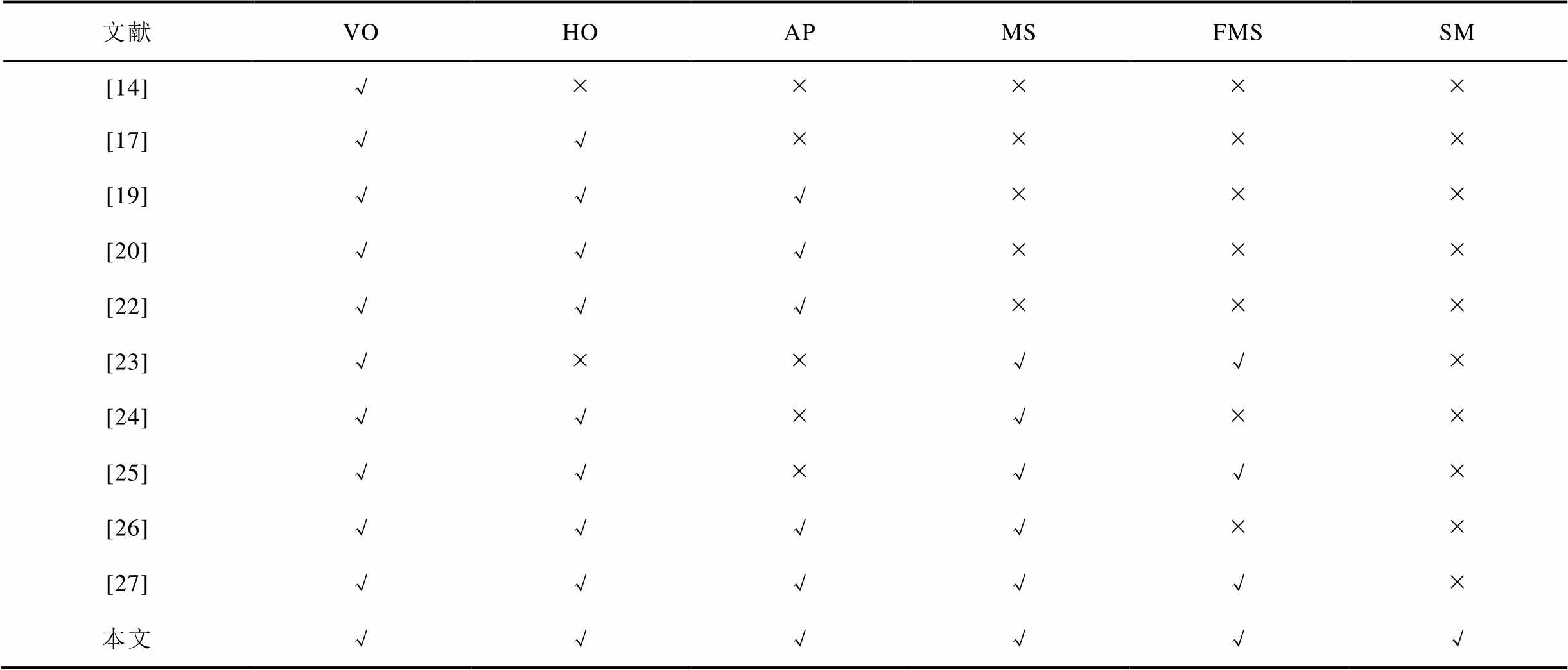
文献VOHOAPMSFMSSM [14]√ÍÍÍÍÍ [17]√√ÍÍÍÍ [19]√√√ÍÍÍ [20]√√√ÍÍÍ [22]√√√ÍÍÍ [23]√ÍÍ√√Í [24]√√Í√ÍÍ [25]√√Í√√Í [26]√√√√ÍÍ [27]√√√√√Í 本文√√√√√√
注:VO(vertical offset)表示垂直偏移,HO(horizontal offset)表示水平偏移,AP(arbitrary position)表示任意位置,MS(magnetic shield)表示带磁屏蔽,FMS(finite magnetic shield)表示有界磁屏蔽,SM(save materials)表示节省材料。
以表1参数将本文所提凸字环形磁屏蔽材料替换为同规格下圆盘形磁屏蔽材料,与本文所提传输结构相比,本文所提凸字环形磁屏蔽材料相比圆盘形磁屏蔽材料节省了19.6%,且随着传输结构与环形磁屏蔽材料内径的增大,该模型节省的材料也会增多。
同时,为了对比相同线圈结构下,磁屏蔽材料为凸字环形与圆盘形时互感的差异。以表1参数分别建立凸字环形与圆盘形磁屏蔽材料传输模型,通过仿真对比磁屏蔽材料为凸字环形与圆盘形时互感的比值。其中,圆盘形磁屏蔽半径与凸字环形磁屏蔽外半径一致为90 mm。其余线圈等参数与凸字环形磁屏蔽传输结构保持不变。
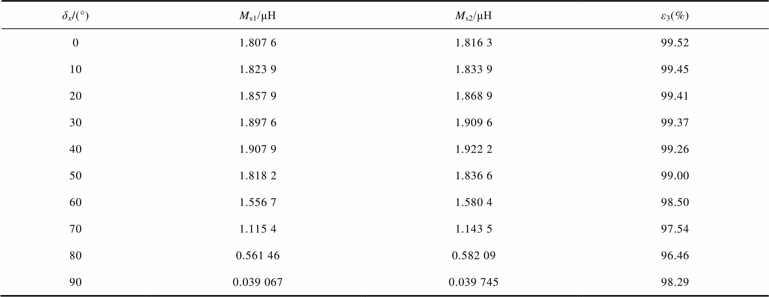
由于仅在水平角度偏转时两种传输结构仿真互感比值存在小于99%的情况。故本文仅绘出水平偏移时两种传输结构仿真互感比值数据见表8,水平角度偏转条件与2.3小节一致。ε3表达式为
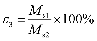 (44)
(44)
式中,ε3为凸字环形磁屏蔽结构仿真互感与圆盘形磁屏蔽结构仿真互感的比值;Ms1为凸字环形磁屏蔽结构互感;Ms2为圆盘形磁屏蔽结构互感。
表8 水平角度偏转时凸字环形磁屏蔽与圆盘形磁屏蔽传输结构互感仿真值间的比值
Tab.8 Ratio between the simulated values of mutual inductance of a convex ring-type magnetic shield and a disk-type magnetic shield transmission structure for horizontal angular deflection
δx/(°)Ms1/μHMs2/μHε3(%) 01.807 61.816 399.52 101.823 91.833 999.45 201.857 91.868 999.41 301.897 61.909 699.37 401.907 91.922 299.26 501.818 21.836 699.00 601.556 71.580 498.50 701.115 41.143 597.54 800.561 460.582 0996.46 900.039 0670.039 74598.29
分析表8可知,凸字环形磁屏蔽与圆盘形磁屏蔽传输结构水平角度偏转情况下在偏转角度小于50°时比值均不小于99%;在偏转角度大于或等于50°时仿真互感比值不小于96.46%,且偏转角度为50°~80°时比值逐渐下降,这是由于凸字环形接收线圈向xOy面投影落入环形挖空覆盖的位置逐渐变大,导致磁通量相比圆盘形磁屏蔽有略微的减小,故有此现象;80°~90°时比值增大是由于此过程接收线圈向xOy面投影逐渐趋近直线,区别仅在于线圈接口处的小突起,故两者差距逐渐变小,比值逐渐增大。
综上所述,除水平角度偏转外,垂直偏移、水平偏移和水平偏移加角度偏转凸字环形磁屏蔽与圆盘形磁屏蔽传输结构互感仿真值间的比值均不小于99%,因此本文所用传输结构互感除高角度偏转外可达到圆盘形磁屏蔽传输结构互感的99%。
本文建立了带凸字环形有界磁屏蔽任意位置圆形线圈互感计算模型,提出了空间边界矢量解析法对互感进行精确求解。此方法通过边界条件求解各区域磁矢势,利用空间矢量坐标变换法结合诺依曼公式得到带凸字环形有界磁屏蔽任意位置圆形线圈互感计算表达式。通过仿真和实验对计算的有效性进行验证。互感计算值和互感实验值之间误差最大为2.86%,互感计算值、互感仿真值和互感实验值具有良好的一致性。在同等规格下,该模型结构相比使用圆盘形磁屏蔽的传输结构节省了19.6%的材料,且其材料节省比例会随着传输结构与环形磁屏蔽材料内径的增大而增大。同时,本文所用传输结构互感除高角度偏转外可达到圆盘形磁屏蔽传输结构互感的99%。相比现有带磁屏蔽材料圆形线圈间的互感计算更具实用价值,更具一般性。本文所提凸字环形有界磁屏蔽线圈结构可为水下供电提供更灵活的布局,且研究结果可为无线电能传输系统结构和参数优化提供理论依据,对下一步带扇型磁屏蔽材料圆形线圈间互感计算的研究也具有一定参考意义。
参考文献
[1] 周玮, 蓝嘉豪, 麦瑞坤, 等. 无线充电电动汽车V2G模式下光储直流微电网能量管理策略[J]. 电工技术学报, 2022, 37(1): 82-91.
Zhou Wei, Lan Jiahao, Mai Ruikun, et al. Research on power management strategy of DC microgrid with photovoltaic, energy storage and EV-wireless power transfer in V2G mode[J]. Transactions of China Electrotechnical Society, 2022, 37(1): 82-91.
[2] 孙淑彬, 张波, 李建国, 等. 多负载磁耦合无线电能传输系统的拓扑发展和分析[J]. 电工技术学报, 2022, 37(8): 1885-1903.
Sun Shubin, Zhang Bo, Li Jianguo, et al. Analysis and development on topologies of multi-load magnetic-coupling wireless power transfer system[J]. Transactions of China Electrotechnical Society, 2022, 37(8): 1885-1903.
[3] 冯天旭, 史可, 孙跃, 等. 基于互感识别及移相角优化的全方位无线电能传输系统靶向传能方法[J]. 电工技术学报, 2023, 38(24): 6581-6595.
Feng Tianxu, Shi Ke, Sun Yue, et al. Targeted power transfer method for omnidirectional wireless power transfer system based on mutual inductance identification and phase-shift angle optimization[J]. Transactions of China Electrotechnical Society, 2023, 38(24): 6581-6595
[4] 苏玉刚, 钱林俊, 刘哲, 等. 水下具有旋转耦合机构的电场耦合无线电能传输系统及参数优化方法[J]. 电工技术学报, 2022, 37(10): 2399-2410.
Su Yugang, Qian Linjun, Liu Zhe, et al. Underwater electric-filed coupled wireless power transfer system with rotary coupler and parameter optimization method[J]. Transactions of China Electrotechnical Society, 2022, 37(10): 2399-2410.
[5] 陈凯楠, 蒋烨, 檀添, 等. 轨道交通350 kW大功率无线电能传输系统研究[J]. 电工技术学报, 2022, 37(10): 2411-2421, 2445.
Chen Kainan, Jiang Ye, Tan Tian, et al. Research on 350 kW high power wireless power transfer system for rail transit[J]. Transactions of China Electrotechnical Society, 2022, 37(10): 2411-2421, 2445.
[6] 陈永洪, 黎祎阳, 杨斌, 等. 基于多中继线圈结构的无线电能传输系统恒流/恒压输出方法[J]. 电力系统自动化, 2022, 46(20): 147-154.
Chen Yonghong, Li Yiyang, Yang Bin, et al. Constant-current/constant-voltage output method for wireless power transfer system based on multi-relay coil structure[J]. Automation of Electric Power Systems, 2022, 46(20):147-154.
[7] Xu Yanhui, Gao Yihao, Cheng Yundan, et al. Substation clustering based on improved KFCM algorithm with adaptive optimal clustering number selection[J]. Global Energy Interconnection, 2023, 6(4): 505-516.
[8] Wu Dehui, Huang Chao, Yang Fan, et al. Analytical calculations of self‐and mutual inductances for rectangular coils with lateral misalignment in IPT[J]. IET Power Electronics, 2019, 12(15): 4054-4062.
[9] Babic S, Akyel C. Improvement in calculation of the self-and mutual inductance of thin-wall solenoids and disk coils[J]. IEEE Transactions on Magnetics, 2000, 36(4): 1970-1975.
[10] Lü Yuelong, Meng Fanyi, Yang Gaohui, et al. A method of using nonidentical resonant coils for frequency splitting elimination in wireless power transfer[J]. IEEE Transactions on Power Electronics, 2015, 30(11): 6097-6107.
[11] Conway J T. Inductance calculations for noncoaxial coils using bessel functions[J]. IEEE Transactions on Magnetics, 2007, 43(3): 1023-1034.
[12] 李中启, 李晶, 全倡辉, 等. 无线电能传输系统带磁屏蔽任意位置矩形线圈的互感计算[J]. 电工技术学报, 2022, 37(17): 4294-4305.
Li Zhongqi, Li Jing, Quan Changhui, et al. Mutual inductance calculation of arbitrarily positioned rectangular coils with magnetic shielding in wireless power transfer systems[J]. Transactions of China Electrotechnical Society, 2022, 37(17): 4294-4305.
[13] Liu Fuxin, Yang Yong, Jiang Dan, et al. Modeling and optimization of magnetically coupled resonant wireless power transfer system with varying spatial scales[J]. IEEE Transactions on Power Electronics, 2016, 32(4): 3240-3250.
[14] Tavakkoli H, Abbaspour-Sani E, Khalilzadegan A, et al. Mutual inductance calculation between two coaxial planar spiral coils with an arbitrary number of sides[J]. Microelectronics Journal, 2019, 85: 98-108.
[15] Choi Hyojin, Lee Sangbin, Cha Cheolung. Optimization of geometric parameters for circular loop antenna in magnetic coupled wireless power transfer[C]//2014 IEEE Wireless Power Transfer Conference, Jeju, Korea (South), 2014: 280-283.
[16] Pirinççi N, Altun H. A new analytical study on mutual inductance calculations for wireless power transfer using magnetic vector potential[J]. IEEE Transactions on Magnetics, 2022, 58(8): 1-14.
[17] Song Kaihong, Feng Jian, Zhao Ran, et al. A general mutual inductance formula for parallel non-coaxial circular coils[J]. The Applied Computational Electromagnetics Society Journal (ACES), 2019: 1385-1390.
[18] Wang Yiming, Xie Xu, Zhou Yan, et al. Calculation and modeling analysis of mutual inductance between coreless circular coils with rectangular cross section in arbitrary spatial position[C]//2020 IEEE 5th Information Technology and Mechatronics EngineeringConference (ITOEC), Chongqing, China, 2020: 1258-1267.
[19] Zhang Xian, Meng Hao, Wei Bin, et al. Mutual inductance calculation for coils with misalignment in wireless power transfer[J]. The Journal of Engineering, 2019, 2019(16): 1041-1044.
[20] Liu Shuo, Su Jianhui, Lai Jidong, et al. Precise modeling of mutual inductance for planar spiral coils in wireless power transfer and its application[J]. IEEE Transactions on Power Electronics, 2021, 36(9): 9876-9885.
[21] Liu Shuo, Su Jianhui, Lai Jidong. Accurate expressions of mutual inductance and their calculation of archimedean spiral coils[J]. Energies, 2019, 12(10): 2017.
[22] Luo Zhichao, Wei Xuezhe. Mutual inductance analysis of planar coils with misalignment for wireless power transfer systems in electric vehicle[C]//2016 IEEE Vehicle Power and Propulsion Conference (VPPC), Hangzhou, China, 2016: 1-6.
[23] Han Yang, Wang Xiaoming. Calculation of mutual inductance based on field-circuit coupling analysis for WPT[C]//2013 5th International Conference on Power Electronics Systems and Applications (PESA), Hong Kong, China, 2013: 1-5.
[24] Luo Zhichao, Wei Xuezhe. Analysis of square and circular planar spiral coils in wireless power transfer system for electric vehicles[J]. IEEE Transactions on Industrial Electronics, 2017, 65(1): 331-341.
[25] Dong Zifan, Li Xiaoming, Liu Sheng, et al. A novel all-direction antimisalignment wireless power transfer system designed by truncated region eigenfunction expansion method[J]. IEEE Transactions on Power Electronics, 2021, 36(11): 12456-12467.
[26] Zhang Xueyi, Quan Changhui, Li Zhongqi. Mutual inductance calculation of circular coils for an arbitrary position with electromagnetic shielding in wireless power transfer systems[J]. IEEE Transactions on Transportation Electrification, 2021, 7(3): 1196-1204.
[27] 李中启, 林志远, 杨鹏, 等. 无线电能传输系统带双层有界磁屏蔽任意位置圆形线圈的耦合系数计算[J]. 电工技术学报, 2022, 37(24): 6306-6318.
Li Zhongqi, Lin Zhiyuan, Yang Peng, et al. Calculation of the coupling coefficient of an arbitrarily positioned circular coil for wireless power transfer system with a double-layered finite magnetic shield[J]. Transactions of China Electrotechnical Society, 2022, 37(24): 6306-6318.
[28] 李厚基, 王春芳, 魏芝浩, 等. 无线电能传输系统用屏蔽层结构的研究[J]. 电工电能新技术, 2019, 38(5): 74-83.
Li Houji, Wang Chunfang, Wei Zhihao, et al. Research of shield structure for wireless power transfer system[J]. Advanced Technology of Electrical Engineering and Energy, 2019, 38(5): 74-83.
Mutual Inductance Calculation Method of Arbitrarily Positioned Circular Coils with Convex Ring Type Finite Magnetic Shielding in Wireless Power Transfer
Abstract In practice, the structure of the wireless power transfer (WPT) system varies for different application scenarios. And the relative position change between the coils of the transmission system will also be caused by the change of mutual inductance. This affects the transmission efficiency. How to quickly and accurately calculated the mutual inductance is a key step in the process of designing and optimizing the structure of WPT systems. Therefore, it is important to study the calculation method of mutual inductance of coils in WPT system under different relative positions. There is no method for mutual inductance calculation of arbitrary positioned circular coils with convex ring type finite magnetic shielding.
This paper established the model for mutual inductance calculation of circular coil with convex ring type finite magnetic shielding in arbitrary position. The spatial boundary vector analysis method is proposed for the exact solution of mutual inductance. This method is solved for the magnetic vector potential in each region by boundary conditions. The space vector coordinate transformation method is utilized. The expression for the calculation of mutual inductance in arbitrary position is obtained by combining Neumann's formula. The validity of the proposed formula is verified by simulations and experiments from four variations of coil relative position vertical offset, horizontal offset, horizontal angular deflection and horizontal offset plus angular deflection.
The calculated results of the proposed formula are compared with the simulated and experimental results as follows: (1) The maximum error of the calculated results with the simulated and experimental results for vertical offset are 2.84% and 2.48%, respectively. (2) The maximum error of the calculated results with the simulated and experimental results for horizontal offset are 1.49% and 2.85%, respectively. (3) The maximum error of the calculated results with the simulated and experimental results for horizontal angular deflection are 3.26% and 2.86%, respectively. 4) The maximum error of the calculated results with the simulated and experimental results for horizontal offset plus angular deflection are 1.84% and 2.47%, respectively.
The calculation model is written Matlab as a program and Ansys Maxwell simulation software under the same equipment for speed comparison. The shortest average time for Ansys Maxwell simulation is 105.636 s, while the longest average time for Matlab program is 0.121 s. Therefore, the proposed calculation method has a significant advantage in calculation speed. The model structure saved 19.6% material compared to the traditional disk type structure under the same parameters. Except for high angle deflection, the mutual inductance can reach 99% of the mutual inductance of the disk type.
In conclusion, the calculated, simulated and experimental values of mutual inductance are in good agreement. The correctness of the proposed calculation method is verified.
keywords:Wireless power transfer, ring type magnetic shield, circular coils, mutual inductance calculation
中图分类号:TM724
DOI: 10.19595/j.cnki.1000-6753.tces.230805
国家重点研发计划(2022YFB3403200)和湖南省自然科学基金(2022JJ30226)资助项目。
收稿日期 2023-05-31
改稿日期 2023-07-23
林志远 男,1996年生,硕士研究生,研究方向为无线电能传输技术。
E-mail: linzhiyuan_19@163.com
李中启 男,1985年生,博士,研究生导师,研究方向为无线电能传输技术。
E-mail: lizhongqi@hnu.edu.cn(通信作者)
(编辑 郭丽军)