Tab.1 Parameters of the CORC cable
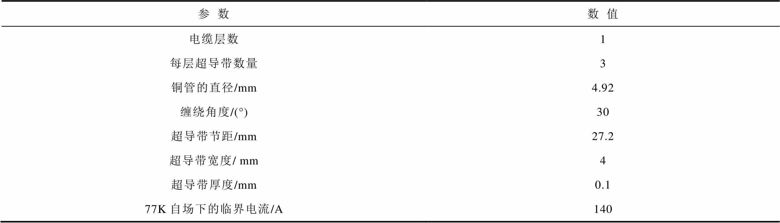
参数数值 电缆层数1 每层超导带数量3 铜管的直径/mm4.92 缠绕角度/(°)30 超导带节距/mm27.2 超导带宽度/ mm4 超导带厚度/mm0.1 77K自场下的临界电流/A140
摘要 采用第二代高温超导(HTS)带材绕制的CORC电缆具有载流能力高、力学性能好等优点,是制造核聚变磁体的理想电缆之一。然而,当由CORC电缆制造的核聚变磁体闭环运行时,现有的工艺很难保证每根CORC电缆的超导带材的接头电阻完全相同,这会对CORC电缆的交流损耗等电气特性产生重要影响。因此,该文搭建了含接头电阻的CORC电缆的三维有限元模型,分析了接头电阻对CORC电缆交流损耗的影响。结果表明,当CORC电缆传输交流电流时,不均匀的接头电阻将导致CORC电缆三根超导带的电流分布不均匀,进而增加了电缆的总体交流损耗。此外,得到了CORC电缆的交流损耗总是随着接头电阻不均匀程度的增加而增大的分析结果。
关键词:高温超导带材 CORC电缆 接头电阻 电流分布 交流损耗
第二代高温超导体(High Temperature Superconducting, HTS)稀土钡铜氧化物(Rare Eeath Barium Copper Oxide, REBCO)在高磁场下有着较强的载流能力[1-5]。基于REBCO布线的三种主流电缆包括TSTC(twisted stacked-tape cable)电缆、罗贝尔(Roebel)电缆、和CORC(conductor on round core)电缆[6-11]。其中,由高温超导带螺旋绕制的CORC电缆因具有交流损耗小、力学性能好等优点正在被应用于聚变磁体和电力输送等领域[12-13]。在这些应用领域中,CORC电缆往往因传输交变电流或处于交变磁场下而产生交流损耗,会增加制冷负担,严重时还会危及整个超导系统的安全稳定运行。因此,研究CORC电缆的交流损耗特性对于保证超导材料的超导特性及整个系统的正常运行至关重要。
目前,一些学者已经对CORC电缆的交流损耗特性进行了研究。文献[14]分析了交流电流和交流磁场同时存在情况下CORC电缆的交流损耗特性,说明了磁场的存在会导致电缆交流损耗的激增。文献[15]通过实验发现了单层CORC电缆在传输交流电流情况下而产生的交流损耗主要取决于圆芯骨架产生的损耗。文献[16]对比了单层、双层CORC电缆的交流传输损耗,并分析了多层CORC结构外层对内层的屏蔽效应。文献[17]主要研究了超导带材超导层厚度对CORC电缆交流损耗的影响。文献[18-19]则讨论了超导带材绕组角度对CORC电缆交流损耗的影响。文献[20]以减小圆芯骨架中的涡流损耗为目标,研究了不同圆芯骨架材料的CORC电缆的交流损耗。
在实际应用中,CORC电缆的接头中会不可避免地出现接头电阻。然而,以现有的工程技术很难保证ReBCO带的接头电阻完全相同。从电路的角度看,这些接头电阻属于并联关系,这会改变CORC电缆不同超导带材的电流分布,进而影响CORC电缆的交流损耗。但接头电阻对CORC电缆交流损耗的影响尚未被研究。因此,本文使用COMSOL/ Multiphysics 软件,建立了含接头电阻的CORC电缆三维有限元模型[21-22],分析了不同接头电阻下CORC电缆的电流及交流损耗分布。此外,本文还讨论了接头电阻不均匀程度对CORC电缆交流损耗的影响。研究结果可为CORC电缆的应用及其制冷系统提供重要参考。
CORC电缆主要由超导带与圆芯骨架组成。其中,多根超导带成一定角度螺旋绕制在圆芯骨架上构成多层结构的CORC电缆。为了便于分析,本文主要对单层超导带材绕制的CORC电缆进行建模研究。选取直径为4.92 mm的铜管为圆芯骨架,三根超导带并联且对称地缠绕在铜管上,缠绕角度为30°,这里的缠绕角度定义为铜管中心轴与超导带中心轴的夹角。为研究接头电阻对CORC电缆交流损耗的影响,在每根超导带的端部截取长度为0.5 mm的一小段用于模拟接头电阻。
模型所采用的超导带的宽度为4 mm,厚度为 0.1 mm,在77 K自场下的临界电流为140 A。CORC电缆的具体参数见表1。
表1 CORC电缆的参数
Tab.1 Parameters of the CORC cable
参数数值 电缆层数1 每层超导带数量3 铜管的直径/mm4.92 缠绕角度/(°)30 超导带节距/mm27.2 超导带宽度/ mm4 超导带厚度/mm0.1 77K自场下的临界电流/A140
在Solidworks中绘制CORC电缆的精确几何拓扑结构,再将绘制好的拓扑结构导入有限元软件。为了使网格质量良好,以达到计算可收敛和求解精确的目的,在超导带与铜管之间设置0.1 mm的空气间隙。CORC电缆模型示意图如图1所示。
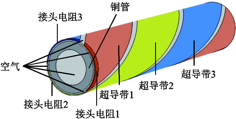
图1 CORC电缆示意图
Fig.1 The schematic diagram of CORC cable
CORC电缆的三根超导带几何拓扑结构对称,且与铜管呈并联关系,考虑到超导带的端部存在接头电阻,则CORC电缆的等效电路模型如图2所示。其中,![]() 表示超导带的接头电阻,
表示超导带的接头电阻,![]() 表示超导带的总电阻,
表示超导带的总电阻,![]() 表示铜管的电阻,
表示铜管的电阻,![]() 表示通入CORC电缆的总电流。
表示通入CORC电缆的总电流。
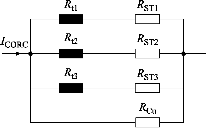
图2 CORC电缆的等效电路模型
Fig.2 Equivalent circuit model of CORC cable
基于CORC电缆的几何及电路模型,本文采用3D H-formulation对麦克斯韦方程进行求解。自变量为磁场强度 ,根据法拉第定律和安培定律,控制方程表示为
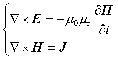 (1)
(1)
式中,E为电场强度,![]() ;
;![]() 为真空磁导率;
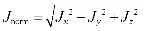
为真空磁导率;![]() 为相对磁导率;J为电流密度,
为相对磁导率;J为电流密度,![]() 。
。
根据欧姆定律,电流密度与电场强度之间的关系为
在模型中,铜管的电阻率![]() 为常数,而超导带的非线性电阻率满足E-J指数关系,即
为常数,而超导带的非线性电阻率满足E-J指数关系,即
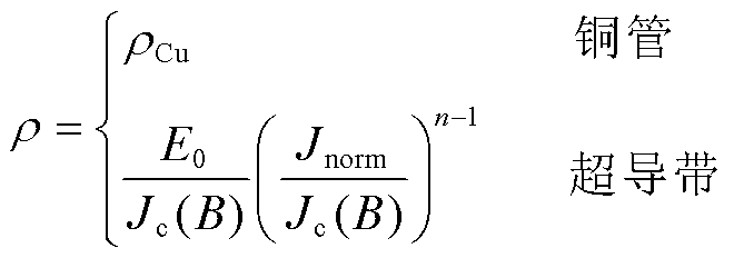 (3)
(3)
式中,![]() 为铜管的电阻率,
为铜管的电阻率,![]() 。
。![]() ,
,![]() ,
, 。
。
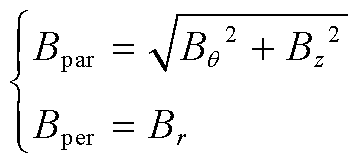
超导带的临界电流密度受磁场(磁感应强度)的影响,表示为
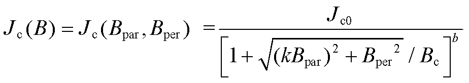 (4)
(4)
式中,Jc0为77K下自场的临界电流密度;Bpar和Bper分别为平行和垂直于超导带表面的磁场分量;![]()
![]()
![]() 。
。
由于CORC电缆是由螺旋缠绕的超导带组成,故Bpar和Bper可以由笛卡尔坐标系转为柱坐标系下运算求解,表示为
 (5)
(5)
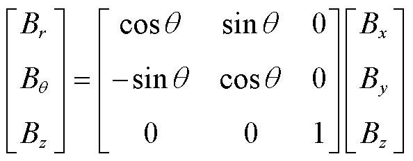 (6)
(6)
CORC电缆上施加直流传输电流或交流传输电流可以通过有限元仿真软件中的全局约束来实现。
直流传输电流表达式为
交流传输电流表达式为
式中,r为电流上升速率;t1为达到传输电流最大值的时间;t2为施加电流的总时间;Id为直流传输电流的最大值;Im为交流传输电流的幅值;![]() 为交流传输电流的频率。
为交流传输电流的频率。
在进行网格划分时,需先对尺寸相对较小的空气间隙进行网格划分,以避免划分的网格尺寸小于最小的几何单元,从而造成模型不收敛。值得注意的是,当传输电流在临界电流以下时,金属层中的电流是可以忽略的。故本仿真模型将超导层的厚度增大100倍至0.1 mm,以减少网格数量,进而提高模型计算效率。
本文所讨论的CORC电缆是由三根超导带和中心的铜管组成的。当CORC电缆三根超导带的接头电阻均为0时,对CORC电缆施加252 A的直流传输电流。为避免电流突增导致模型不收敛,在0~100 ms内使电流以一定速率上升至稳定值,然后维持不变。CORC电缆的电流分布如图3所示。可见,通入电缆的总电流平均分布到三根超导带上,流过铜管的电流几乎为零。
CORC电缆三根超导带接头电阻分别为2 mW、4 mW和6 mW时,对CORC电缆施加252 A的直流传输电流。CORC电缆的电流分布如图4所示。
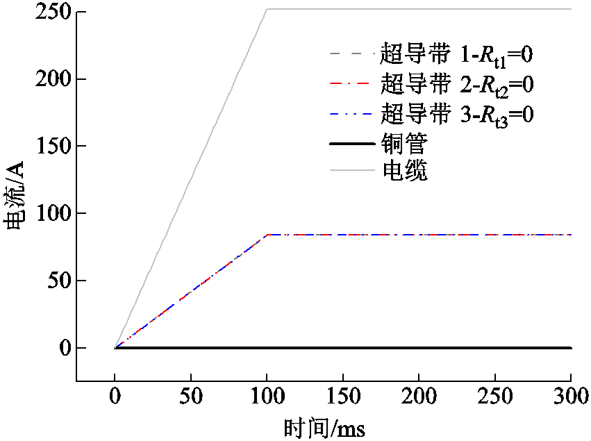
图3 直流传输电流下,接头电阻为零的CORC电缆的电流分布
Fig.3 The current distribution of CORC cable with zero joint resistance under DC transport current
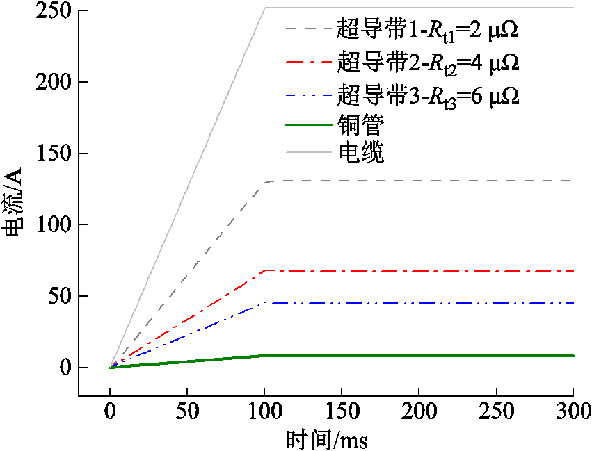
图4 直流传输电流下,不均匀接头电阻CORC电缆的电流分布
Fig.4 The current distribution of CORC cable with uneven joint resistances under DC transport current
由图4可见,由于CORC电缆超导带的接头电阻远小于铜管的电阻,故绝大部分直流传输电流是从超导带流过,只有小部分电流流过铜管。说明接头电阻的大小及分布会影响CORC电缆的载流能力。
CORC电缆三根超导带属于并联关系,各超导带两端的电压相等,不均匀的接头电阻直接导致了CORC电缆不同超导带中的直流传输电流不均匀分布。由图4可知,三根超导带的接头电阻之比![]() ,相应地,通过超导带的直流传输电流之比
,相应地,通过超导带的直流传输电流之比![]() 。可见,各超导带的直流电流主要按照接头电阻的大小分布。三根超导带中接头电阻最大的超导带传输的电流最小,接头电阻最小的超导带传输电流最大。这在一定程度上验证了模型的准确性。
。可见,各超导带的直流电流主要按照接头电阻的大小分布。三根超导带中接头电阻最大的超导带传输的电流最小,接头电阻最小的超导带传输电流最大。这在一定程度上验证了模型的准确性。
CORC电缆通入交流传输电流时,会产生交流损耗,进而对冷却系统造成负担,增大运行成本。本文通过仿真模拟了不均匀接头电阻对CORC电缆交流损耗的影响。
CORC电缆的交流损耗通过对后半周期功率密度积分的两倍计算得到,即
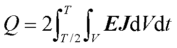 (9)
(9)
式中,![]() ;
;![]() 为积分区域的体积。对于超导带和铜管,交流损耗
为积分区域的体积。对于超导带和铜管,交流损耗![]() 的单位是J/(cycle·m);对于接头电阻,交流损耗
的单位是J/(cycle·m);对于接头电阻,交流损耗![]() 的单位是J/cycle。
的单位是J/cycle。
为探究交流传输电流下,CORC电缆中超导带的接头电阻对各超导带及铜管的传输电流分配和交流损耗的影响,仿真中三根超导带的接头电阻分别设置为2 mW、4 mW和6 mW。对CORC电缆施加频率为50 Hz、幅值为252 A的交流传输电流,CORC电缆的电流分布如图5所示。
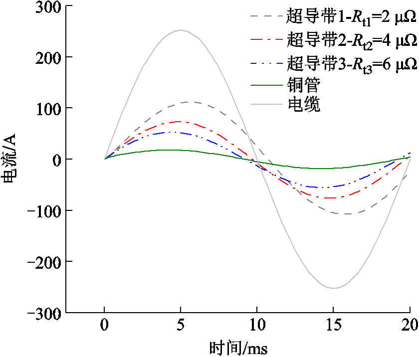
图5 交流传输电流下,不均匀接头电阻CORC电缆的电流分布
Fig.5 The current distribution of CORC cable with uneven joint resistances under AC transport current
由图5可以看出,当接头电阻不均匀的CORC电缆传输交流电流时,三根超导带传输电流的幅值并没有像直流传输电流一样按照接头电阻的大小比例分配,且各超导带中的交流传输电流相位也不相同。这是由于CORC电缆通入交流传输电流时,超导带中不仅存在接头电阻,而且超导带由于其螺旋缠绕结构而存在电抗,带中的交流传输电流的分布受电阻和电抗共同作用与影响。因此,三根超导带接头电阻的不同导致对交流传输电流呈现的阻抗互不相同,进而导致各超导带中传输的交流电流相位和幅值不相同。
不同的接头电阻使得流过三根超导带的传输电流不同,进而导致接头电阻部分产生的交流损耗不同。故有必要分析三根超导带的接头电阻所产生的损耗大小关系,如图6所示。从稳定后的损耗波形来看,最大的接头电阻产生的损耗最小,而两个较小的接头电阻产生的交流损耗相对较大。
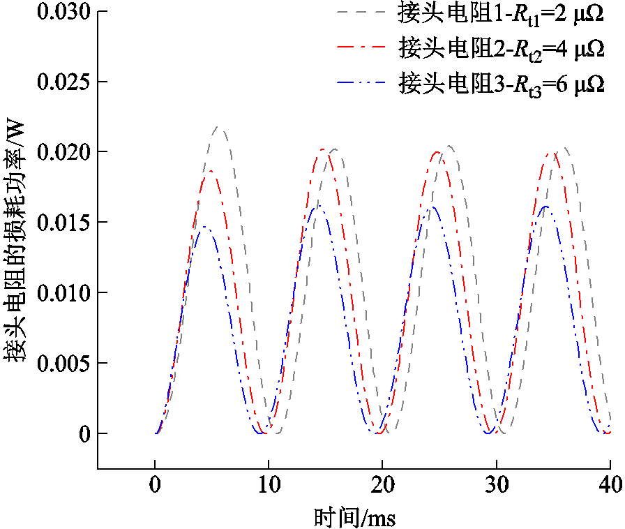
图6 CORC电缆超导带的接头电阻产生的损耗功率
Fig.6 Loss caused by joint resistances of superconducting tapes of CORC cable
图7为不均匀接头电阻下CORC电缆各部分的交流损耗。结果表明,只施加交流传输电流时,超导带产生的损耗只是占单层CORC电缆除接头电阻外总损耗的一小部分,大部分损耗来自铜管产生的涡流损耗。根据E-J指数模型,传输电流越大,超导带的纯电阻越大,又由于损耗与电流的二次方成正比,故传输电流大的超导带产生的损耗远大于传输电流小的超导带产生的损耗。
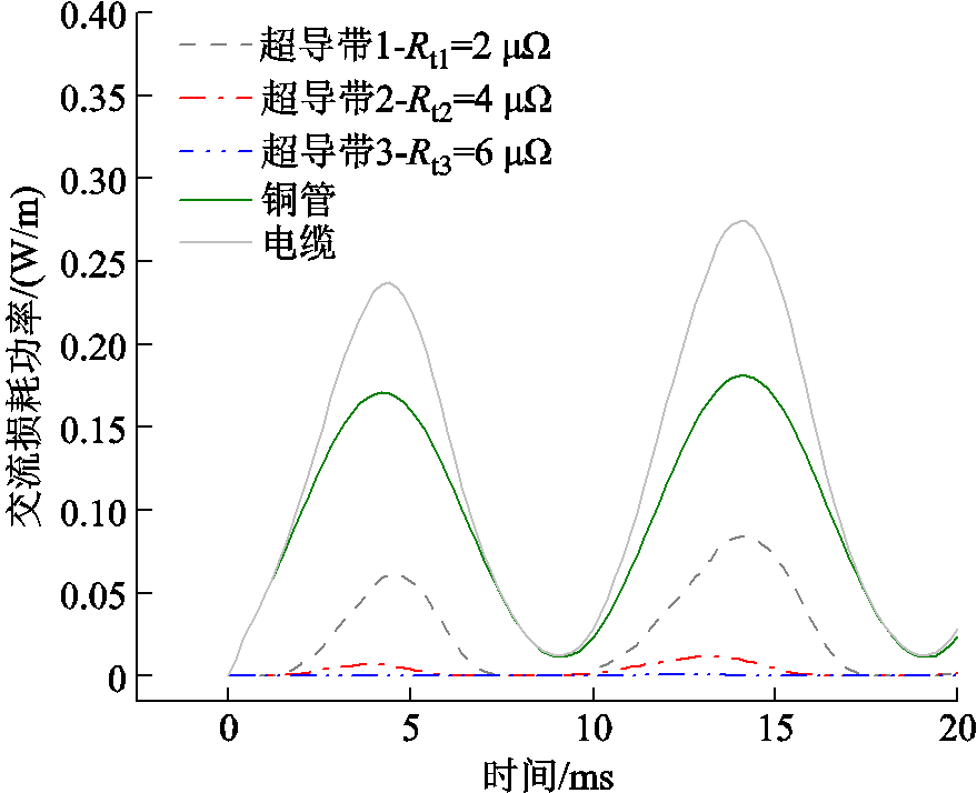
图7 不均匀接头电阻CORC电缆的交流损耗功率
Fig.7 AC loss power of CORC cable withuneven joint resistances
综上所述,CORC电缆通入交流传输电流时,由于电抗的存在,三根超导带的传输电流不是按照接头电阻的大小比例分配,而是按照阻抗进行分配。且不均匀的接头电阻直接导致三根超导带的传输电流不均匀,进而使各超导带及其接头电阻部分产生的损耗不相同。此外,交流传输电流下,受不均匀接头电阻和CORC电缆单层结构共同的影响,铜管产生的损耗占CORC电缆除接头电阻外总损耗的绝大部分。
本节主要研究交流传输电流下接头电阻的不均匀程度对CORC电缆交流损耗的影响。根据三根超导带接头电阻之间的相对大小关系可以将其分三类:①大-中-小(Large-Middle-Small, LMS):三根超导带接头电阻值从大到小各不相同;②大-大-小(Large-Large-Small, LLS):两根超导带的接头电阻较大,一根超导带的接头电阻较小;③小-小-大(Small-Small-Large, SSL):两根超导带的接头电阻较小,一根超导带的接头电阻较大。
接头电阻的不均匀程度h定义为
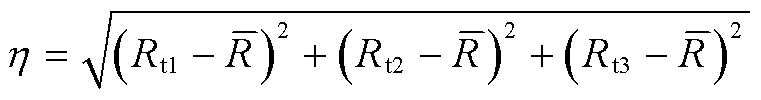 (10)
(10)
式中,![]() 为三根超导带接头电阻的平均值。当
为三根超导带接头电阻的平均值。当![]() 时,说明CORC电缆中各超导带的接头电阻相同。
时,说明CORC电缆中各超导带的接头电阻相同。
探究接头电阻的不均匀程度对CORC电缆交流损耗产生的影响,需要确保三根超导带的并联总电阻Rtotal为一个固定值。换言之,Rt1、Rt2和Rt3要满足以下等式关系。
 (12)
(12)
本文假设各超导带接头电阻均相等时,Rt1=Rt2=Rt3=4 mW,则总电阻Rtotal=4/3 mW。保持总电阻不变,取接头电阻的不均匀程度分别为0.3、0.6、0.9、1.2、1.5、1.8和2.1。采用粒子群算法求解出一系列接头电阻如图8所示。
在CORC电缆上施加幅值为252A的工频交流传输电流,图9为接头电阻的不均匀程度对CORC电缆交流损耗的影响。由图9a可得,对于均匀的接头电阻,三根超导带传输的电流幅值相同,其螺旋缠绕的结构可以抵消一部分磁场;而非均匀接头电阻CORC电缆的磁场抵消效应相对较弱。因此,理想状况下带有均匀接头电阻的CORC电缆超导带的交流损耗总是小于非均匀接头电阻CORC电缆超导带的交流损耗。
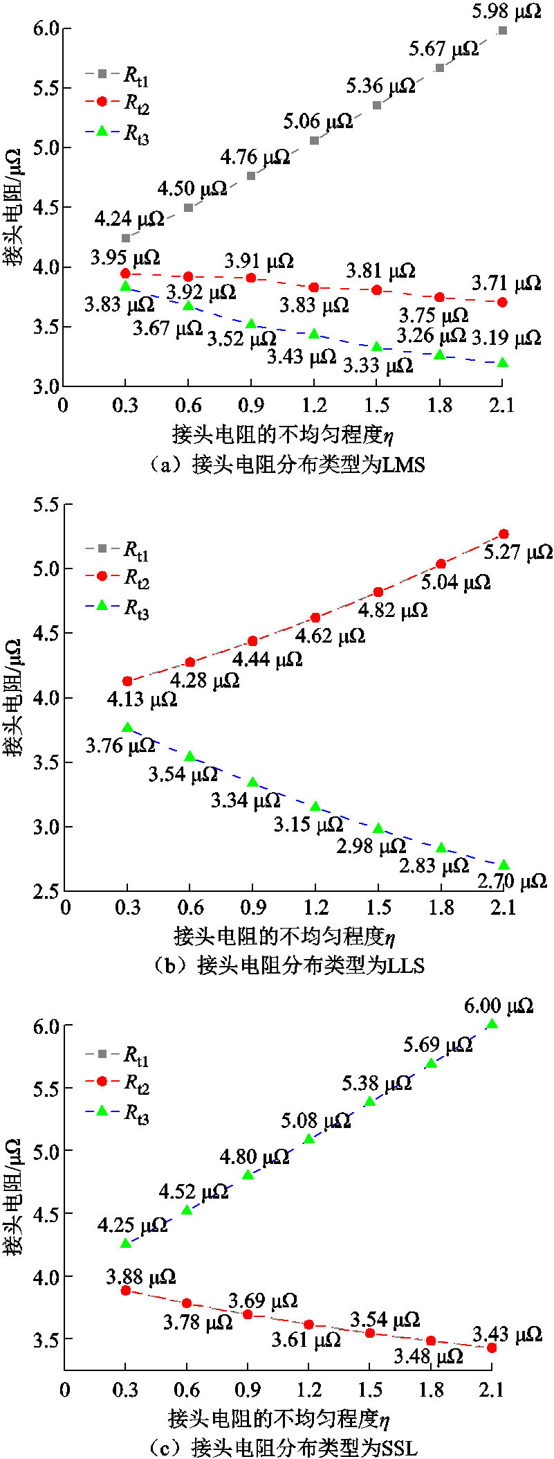
图8 接头电阻的不均匀程度对应的接头电阻阻值
Fig.8 The resistance values of the joint resistances corresponding to the uneven degree of the joint resistances
不论是哪一种接头电阻分布类型,超导带的交流损耗都是随着接头电阻不均匀程度的增加而增大。并且,接头电阻分布类型为LLS时,超导带的交流损耗受接头电阻不均匀程度的影响更大。当不均匀程度为0.9时,超导带的交流损耗约为均匀接头电阻的超导带的交流损耗的1.27倍。
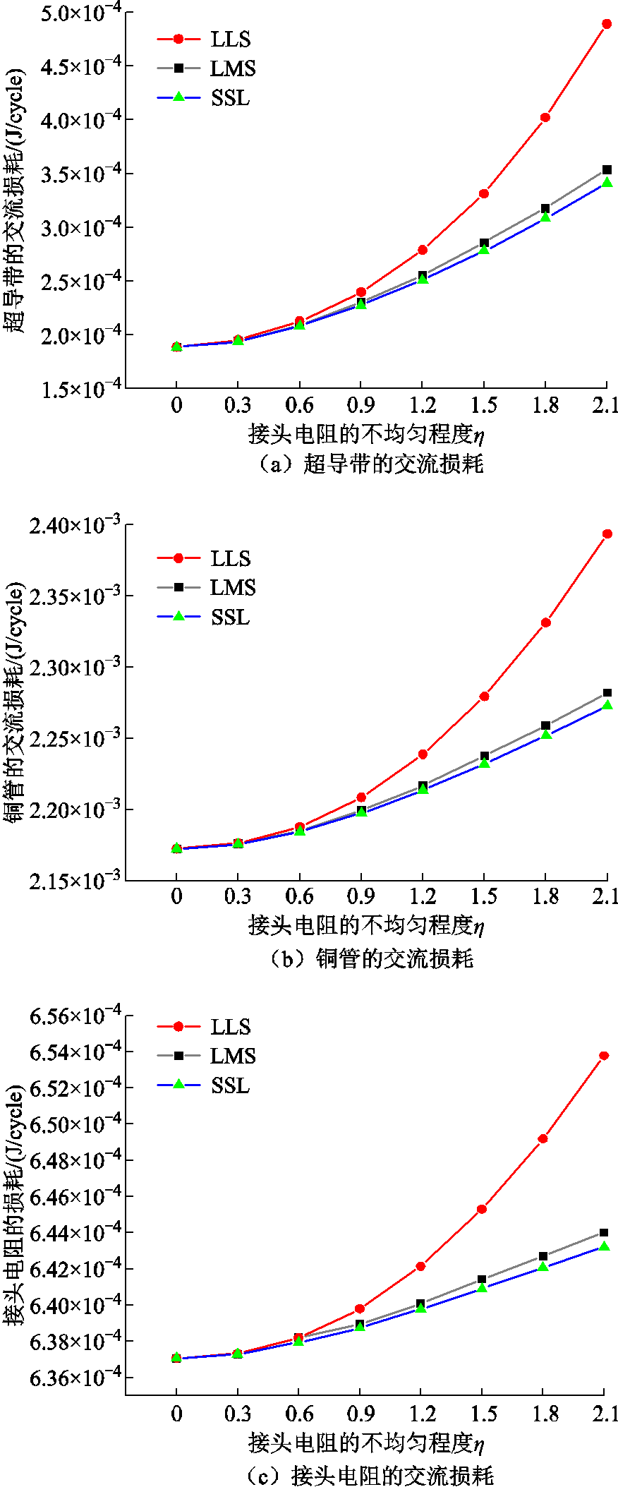
图9 接头电阻的不均匀程度对CORC电缆交流损耗的影响
Fig.9 The influence of the uneven degree of joint resistances on the AC loss of CORC cable
比较CORC电缆接头电阻分布类型分别为LMS、LLS、SSL时,接头电阻处于同一不均匀程度下超导带产生的交流损耗。LLS接头电阻分布类型的CORC电缆的超导带损耗最大。这可能是由于接头电阻不均匀程度相同时,相较于其他两种接头电阻分布类型的CORC电缆,LLS类型的CORC电缆有两根超导带的接头电阻是大电阻,一根超导带的接头电阻是小电阻,有更多的电流流向接头电阻小的超导带,所以其呈现的电流极值是最大的。又因为损耗与电流的二次方成正比,故三根超导带总的交流损耗主要取决于传输电流最大的超导带。
接头电阻不均匀程度对铜管交流损耗的影响如图9b所示。结果表明,接头电阻在同一种分布类型下,其不均匀程度越大,铜管产生的损耗越大,这是由于随着接头电阻的不均匀程度增加,三根超导带的磁感应强度差别增大,螺旋缠绕超导带之间磁场的抵消效应就会减弱,进而铜管感应的涡流增强。LLS接头电阻分布类型下,电流达到峰值时超导带的磁感应强度如图10所示。图9c为接头电阻不均匀程度对接头电阻产生的损耗的影响。在同一种接头电阻分布类型下,接头电阻越不均匀,其产生的损耗越大。在同一不均匀程度下,分布类型为LLS的接头电阻产生的损耗最大。
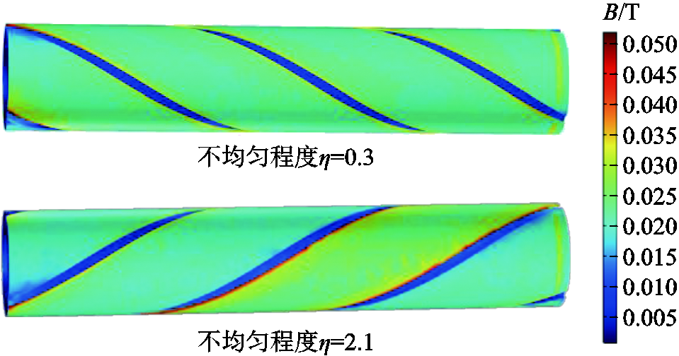
图10 LLS接头电阻分布类型下,电流达到峰值时超导带的磁感应强度
Fig.10 The type of joint resistance distribution is LLS, and the magnetic induction intensity of the superconducting tapes when the current reaches the peak value
综上所述,均匀接头电阻的CORC电缆产生的交流损耗总是小于非均匀接头电阻的CORC电缆产生的交流损耗。在同一种接头电阻分布类型下,超导带、铜管和接头电阻的损耗均随着接头电阻不均匀程度的增加而增加,故CORC电缆总的交流损耗也随着接头电阻不均匀程度的增加而增加。且分布类型为LLS的接头电阻对CORC电缆交流损耗的影响格外显著。因此,为减少交流损耗,在实际工程制造中,应尽量避免CORC电缆接头电阻不均匀,尤其是分布类型为LLS的接头电阻。
本文主要研究了不均匀接头电阻对CORC电缆的电流分布和交流损耗的影响。基于等效电路分析,建立了含接头电阻的CORC电缆三维有限元模型。本文的结论可以总结如下:
1)CORC电缆接头电阻的不均匀直接导致了各超导带的传输电流不一致:当传输直流电流时,各超导带的电流分布主要受到接头电阻大小影响;当传输交流电流时,超导带由于其螺旋缠绕结构而存在电抗,因此各超导带的电流分布和相位受到超导带电抗和接头电阻共同作用的影响。
2)由于超导带存在接头电阻和电抗,当CORC电缆传输交流电流时,部分交流电流会流入铜管而产生损耗。相比于超导带产生的交流损耗,铜管产生的损耗在CORC电缆传输交流电流的总损耗占比更大。
3)当传输交流电流时,带有均匀接头电阻的CORC电缆的交流损耗总是小于带有非均匀接头电阻CORC电缆的交流损耗。CORC电缆的总交流损耗总是随着接头电阻不均匀程度呈正相关关系;当超导带接头电阻呈Large-Large-Small分布时,CORC电缆交流损耗受接头电阻不均匀程度影响最明显。
综上所述,在实际制造过程中,应尽量减小接头电阻,并保证CORC电缆接头电阻相对均匀,以减少交流损耗。
参考文献
[1] Larbalestier D, Gurevich A, Feldmann D M, et al. High-Tc superconducting materials for electric power applications[J]. Nature, 2001, 414(6861): 368-377.
[2] 肖立业, 林良真. 超导输电技术发展现状与趋势[J]. 电工技术学报, 2015, 30(7):1-9.
Xiao Liye, Lin Liangzhen. Status quo and trends of superconducting power transmission technology[J]. Transactions of China Electrotechnical Society, 2015, 30(7) ):1-9.
[3] 张国民, 陈建辉, 邱清泉, 等. 超导直流能源管道的研究进展[J]. 电工技术学报, 2021, 36(21): 4389-4398, 4428.
Zhang Guomin, Chen Jianhui, Qiu Qingquan, et al. Research progress on the superconducting DC energy pipeline[J]. Transactions of China Electrotechnical Society, 2021, 36(21): 4389-4398, 4428.
[4] 诸嘉慧, 栗会峰, 陈晓宇, 等. 高温超导电缆交直流伏安特性测试与分析[J]. 电工技术学报, 2016, 31(24)120-125
Zhu Jiahui, Li Huifeng, Chen Xiaoyu, et al. Test and analysis on the DC and AC I-V characteristics of high temperature superconducting cable[J]. Transactions of China Electrotechnical Society, 2016, 31(24):120-125.
[5] 林良真. 我国超导技术研究进展及展望[J]. 电工技术学报, 2005, 20(1): 1-7.
Lin Liangzhen. Recent advances and prospect in the development of superconducting technology in China[J]. Transactions of China Electrotechnical Society, 2005, 20(1):1-7.
[6] Yagotintsev K, Anvar V A, Gao P, et al. AC loss and contact resistance in REBCO CORC®, Roebel, and stacked tape cables[J]. Superconductor Science and Technology, 2020, 33(8): 085009.
[7] Grilli F, Vojenčiak M, Kario A, et al. HTS roebel cables: self-field critical current and AC losses under simultaneous application of transport current and magnetic field[J]. IEEE Transactions on Applied Superconductivity, 2016, 26(4): 1-5.
[8] Goldacker W, Grilli F, Pardo E, et al. Roebel cables from REBCO coated conductors: a one-century-old concept for the superconductivity of the future[J]. Superconductor Science and Technology, 2014, 27(9): 093001.
[9] Grilli F, Zermeño V M R, Takayasu M. Numerical modeling of twisted stacked tape cables for magnet applications[J]. Physica C: Superconductivity and Its Applications, 2015, 518: 122-125.
[10] Obana T, Terazaki Y, Yanagi N, et al. Self-field measurements of an HTS twisted stacked-tape cable conductor[J]. Cryogenics, 2020, 105: 103012.
[11] 李显皓, 徐颖, 任丽, 等. 非均匀高温超导带材对CORC电缆失超特性的影响研究[J]. 电工技术学报, 2022, 37(19): 5044-5055.
Li Xianhao, Xu Ying, Ren Li, et al. Influence of non-uniform high temperature superconducting tapes on quench characteristics of CORC cable[J]. Transactions of China Electrotechnical Society, 2022, 37(19):5044-5055.
[12] Weiss J D, Mulder T, ten Kate H J, et al. Introduction ofCORC®wires: highly flexible, round high-temperature superconducting wires for magnet and power transmission applications[J]. Superconductor Science and Technology, 2017, 30(1): 014002.
[13] Hu Rui, Yuan Yuchao, Chen Yanjun, et al. Numerical study on mechanical properties of conductors on round core cables[J]. IEEE Transactions on Applied Superconductivity, 2021, 31(5): 1-5.
[14] Yang Jiabin, Tian Mengyuan, Shen Boyang, et al. Numerical study on AC loss characteristics of conductor on round core cables under transport current and magnetic field[C]//2020 IEEE International Conference on Applied Superconductivity and Electromagnetic Devices (ASEMD), Tianjin, China, 2020: 1-2.
[15] Terzioğlu R, Vojenčiak M, Sheng J, et al. AC loss characteristics of CORC® cable with a Cu former[J]. Superconductor Science and Technology, 2017, 30(8): 085012.
[16] Yang Jiabin, Li Chao, Tian Mengyuan, et al. Analysis of AC transport loss in conductor on round core cables[J].Journal of Superconductivity and Novel Magnetism, 2022, 35(1): 57-63.
[17] Tian Mengyuan, Yang Jiabin, Shen Boyang, et al. Analysis on the effect of superconductor layer thickness on the AC loss of conductor on round core (CORC) cables[J]. IEEE Transactions on Applied Superconductivity, 2021, 31(8): 1-4.
[18] Li Qizhan, Lu Yuming, Zhao Wenwen, et al. Effects of winding angle on losses of CORC cable—a numerical study[J]. IEEE Transactions on Applied Superconductivity, 2023, 33(2): 1-7.
[19] Zhao J, Gao S Y, Wu B H, et al. Effect of winding methods: transport AC losses in CORC coils[J]. Super-conductor Science and Technology, 2022, 35(11): 115007.
[20] Ye Haosheng, Li Wenrong, Li Zhuyong, et al. Effect of core materials on the electrical properties of superconducting conductor on round core cable[J]. IEEE Transactions on Applied Superconductivity, 2020, 30(4): 1-5.
[21] Li Gengyao, Li Chao, Xin Ying, et al. Dynamic modelling methodology for an HTS energy converter using moving mesh[J]. Superconductor Science and Technology, 2021, 34(10): 105006.
[22] Li Chao, Xing Yuying, Zhao Beitao, et al. Dynamic resistance of series-connected HTS stacks considering electromagnetic and thermal coupling[J]. IEEE Tran-sactions on Applied Superconductivity, 2022, 32(4): 1-5.
Abstract The conductor on round core (CORC) cable, spirally wound by high temperature superconducting tapes, will generate AC loss, which increases the heat burden and even endangers the safe operation of the entire superconducting system.In practical applications, joint resistances will inevitably appear in the joints of CORC cable. However, the existing technology is difficult to ensure that the joint resistance of each superconducting tape of the CORC cable be exactly same. The differences of joint resistance will have significant impacts on the AC loss of the CORC cable. Therefore, a 3D finite element model of CORC cable with joint resistance is established, and studies on the influence of joint resistances on AC loss of CORC cable is carries out.
A CORC cable based on finite element software is built.Firstly, a small segment is cut at the end of each superconducting tape of CORC cable to simulate the joint resistance, and the geometric model and equivalent circuit model of the CORC cable are constructed. Secondly, it is meshed and optimized. Finally, the Maxwell Equations are solved based on H-formulation. The model can accurately and effectively simulate the influence of joint resistances on the electrical characteristics of CORC cable.
The simulation results show that when the transport DC current is applied to the CORC cable with no joint resistance, the transport DC current is evenly distributed to the three superconducting tapes. When the ratio of the joint resistances of the three superconducting tapes is ![]() , the ratio of the DC transport current through the superconducting tapes is
, the ratio of the DC transport current through the superconducting tapes is ![]() , which verifies the accuracy of the model. When the AC transport current is applied to the CORC cable, the transport current of the three superconducting tapes is not distributed according to the ratio of the joint resistances, and the phase of the AC transport current in each superconducting tape is also different.
, which verifies the accuracy of the model. When the AC transport current is applied to the CORC cable, the transport current of the three superconducting tapes is not distributed according to the ratio of the joint resistances, and the phase of the AC transport current in each superconducting tape is also different.
The following conclusions can be drawn from the simulation analysis: (1) Uneven joint resistances of the CORC cable directly leads to the inconsistency of the transport current of each superconducting tape. When the DC current is transported, the current distribution of each superconducting tape is mainly affected by the joint resistances.When the AC current is transported, the superconducting tapes have reactance due to their spiral winding structure, so the current distribution and phase of each superconducting tape are affected by the reactance and the joint resistance of the superconducting tape. (2) Due to the joint resistance and reactance of the superconducting tape, when the CORC cable transports AC current, part of the AC current will flow into the former and cause loss. Compared with the AC loss generated by the superconducting tapes, the loss generated by the former accounts for a larger proportion of the total loss of the CORC cable. (3) When the AC current is transported, the AC loss of the CORC cable with even joint resistances is always smaller than that of the CORC cable with uneven joint resistances. The total AC loss of the CORC cable is always positively correlated with the uneven degree of the joint resistances.When the joint resistance distribution type of the superconducting tapes is Large-Large-Small, the AC loss of the CORC cable is most obviously affected by uneven degree of the joint resistances.
Keywords:High temperature superconducting (HTS) tape, CORC cable, joint resistance, current distribution, AC loss
中图分类号:TM26
DOI: 10.19595/j.cnki.1000-6753.tces.230970
国家自然科学基金(52107022)和新奥能源研究院材料研发基金(9710K2022-021)资助项目。
收稿日期 2023-06-19
改稿日期 2023-08-23
李 超 男,1988年生,副教授,硕士生导师,研究方向为智能电网保护与控制、高温超导应用技术、超导磁体无线励磁技术等。
E-mail:lichao_tju@126.com(通信作者)
杨文超 女,2000年生,硕士研究生,研究方向为CORC电缆电磁热特性分析。
E-mail:yangwenchaotj@163.com
(编辑 郭丽军)