Tab.1 Odd harmonics distortion limits
奇次谐波畸变率限值(%) 3~9<4.0 11~15<2.0 17~21<1.5 23~33<0.6 35及以上<0.3
摘要 重复控制因其能有效抑制谐波信号而被广泛应用于逆变器控制中,但其动态性能较差,且在电网频率波动时谐波抑制性能下降严重。为此,该文提出一种频率自适应前馈双模重复-比例控制。在双模重复控制的内模中加入前馈环节改善系统的动态性能,并使用无限脉冲响应滤波器实现对电网频率波动导致的分数延迟精确近似。该文给出频率自适应前馈双模重复-比例控制的原理、稳定性分析和参数优化设计过程。实验结果证明了所提出的控制方法在电网频率波动时能抑制并网电流谐波,且具有较好的动态性能。
关键词:微电网 重复控制 并网逆变器 频率自适应 无限脉冲响应滤波器
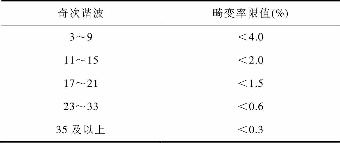
高比例可再生能源、高比例电力电子设备的大规模应用使“双高”电力系统呈现新特性[1]。电力电子设备惯性小,基于可再生能源的微电网[2-3]发电功率与负载功率不平衡将导致微电网频率波动。同时,电力电子设备的非线性特性显著,导致系统谐波含量增加。这将致使微电网出现等幅振荡[4]进而可能导致微电网系统不稳定。并网逆变器作为连接发电单元与负载/微电网的核心部件,要为负载/微电网提供高质量的并网电流[5-7]。其中,电流的总谐波畸变率(Total Harmonic Distortion, THD)是衡量电流质量的重要指标[8-9]。根据IEEE Std. 519- 2022[10]和GB/T 37408-2019[11]的要求,并网电流的THD应低于5%,奇次谐波畸变率限值见表1,偶次谐波畸变率限值应小于同范围内奇次谐波限制的25%。因此,研究微电网频率波动时抑制逆变器并网电流谐波方法具有重要意义。
表1 奇次谐波畸变率限值
Tab.1 Odd harmonics distortion limits

奇次谐波畸变率限值(%) 3~9<4.0 11~15<2.0 17~21<1.5 23~33<0.6 35及以上<0.3
重复控制(Repetitive Control, RC)[12-14]因其能实现对基波周期信号进行无静差跟踪及倍频谐波信号的扰动消除,而被广泛应用于逆变器控制中。但由于RC内模的递归结构和固有延迟,导致RC的动态性能较差[15]。因此,文献[15-16]提出重复控制与比例积分控制结合的复合控制器,改善了系统的动态性能,但控制器存在耦合,导致并网逆变器动态过程中发生电流畸变。文献[17]提出了一种快速RC,进一步提高系统的动态性能,可以消除奇次谐波,但无法消除偶次谐波。文献[18]提出了插入式双模重复-比例积分控制,提高了系统的响应速度,还可以根据需求不同程度地抑制奇、偶次谐波,但插入式结构下重复控制增益较小,在一定程度上影响谐波抑制效果。文献[19-20]提出由重复控制并联比例环节构成的复合控制器(controller based on Repetitive Control and Proportional Control, RC-PC),可等效为比例积分多谐振控制器,具有优秀的跟踪参考电流和抑制谐波的能力。文献[21]在RC-PC结构上加入了分数阶相位超前补偿器,对系统的相位滞后进行精细补偿,进一步提高系统动态性能。文献[22]提出的双模重复控制(Dual-Mode Repetitive Control, DMRC)具有独立的奇次内模和偶次内模,可以不同程度地抑制奇、偶次谐波,并且可以在不损失精度的情况下加快跟踪误差的收敛速度。文献[23]提出了一种DMRC与无差拍控制结合的复合控制器,结合了两种控制器的优点,具有优秀的稳态性能和良好的动态性能,但无差拍控制对系统建模准确度要求高。文献[24]在DMRC的基础上使用相移陷波滤波器抑制谐波电流的主频率分量,提高系统动态性能,但计算较为复杂。
针对电网频率波动导致RC谐波抑制能力变差的问题,文献[25]提出了一种多内模重复控制,通过增加谐波频率处的带宽,减少频率变化对系统性能的影响。文献[26]提出通过改变采样频率的方法保证重复控制能跟踪基波周期参考信号,但改变采样频率会使数字系统的实现更复杂。文献[27-29]提出了使用有限脉冲响应(Finite Impulse Response, FIR)滤波器实现分数延迟的RC策略,该方法便于实时调整,但FIR滤波器的幅频响应在低频段衰减,需要更高阶次才能接近分数阶延迟。由文献[30-31]可知,基于Thiran公式的无限脉冲响应(Infinite Impulse Response, IIR)滤波器可以用较小的阶数实现与FIR相同的频率特性。IIR滤波器需要的乘法器更少,延迟时间更短,具有更低的计算复杂度,但在DMRC中还没有相关研究。
因此,为了进一步提高双模重复控制的动态响应速度,本文提出了一种新的前馈双模重复-比例控制(Feedforward Dual-Mode Repetitive Control and Proportional Control, FDMRC-PC)方法。同时,为了提高微电网频率波动时双模重复控制器的谐波抑制效果,本文提出一种基于IIR滤波器的频率自适应前馈双模重复-比例控制(Frequency Adaptive FDMRC-PC, FA-FDMRC-PC)方法。该控制方法对电网频率波动具有自适应性,能在电网波动时有效抑制逆变器并网电流谐波,并具有较好的动态性能。
在双模重复控制的奇、偶次内模中分别加入前馈环节,构成前馈双模重复控制(Feedforward Dual- Mode Repetitive Control, FDMRC),其结构如图1所示。传递函数为
 (1)
(1)
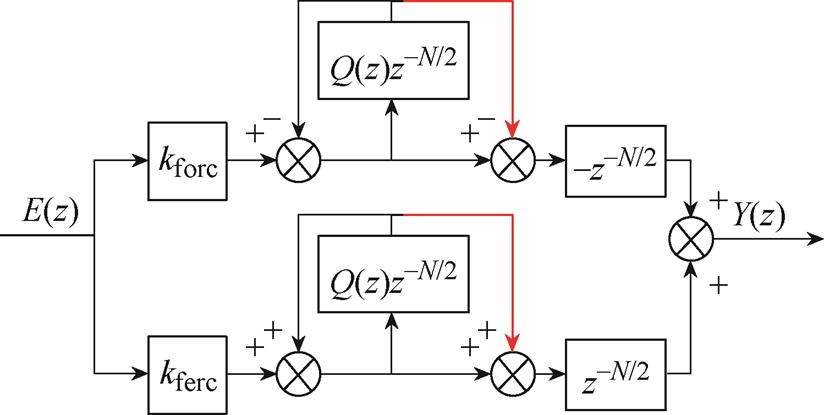
图1 FDMRC结构
Fig.1 Structure diagram of FDMRC
图1中,kforc为奇次增益,kferc为偶次增益,Q(z)为内模滤波器,N为每个周期的延迟拍数,且N=fs/fg,fs为采样频率,fg为电网频率。当Q(z)= (z+2+z-1)/4,重复控制增益kforc=kferc=korc=kerc=krc=1,korc、kerc分别为DMRC的奇次增益和偶次增益,krc为RC的重复控制增益,且采样频率为10 kHz时,FDMRC、DMRC和RC第7次谐波频率处的伯德图如图2所示。由图2可知,FDMRC在谐波频率处提供的开环增益高于DMRC和RC,因此所提出的FDMRC具有更好的谐波抑制能力。
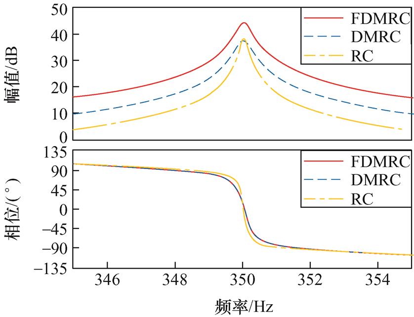
图2 FDMRC、DMRC和RC第7次谐波频率处伯德图
Fig.2 Bode plots of FDMRC, DMRC and RC at the seventh harmonic frequency
为了提高前馈双模重复控制对电网频率波动的适应性,本文提出基于IIR滤波器的频率自适应前馈双模重复-比例控制方法。FA-FDMRC-PC结构如图3所示。图3中,kp为比例环节,zm为相位超前补偿器,S(z)为补偿器,通常为低通滤波器,dg为扰动信号。由文献[20]可知,RC与kp并联可以提高系统的动态响应速度,同理可得,FDMRC并联kp也可以改善动态性能。将yrc到ig看作是比例控制的电流环,将其作为新的被控对象P0(z),传递函数为
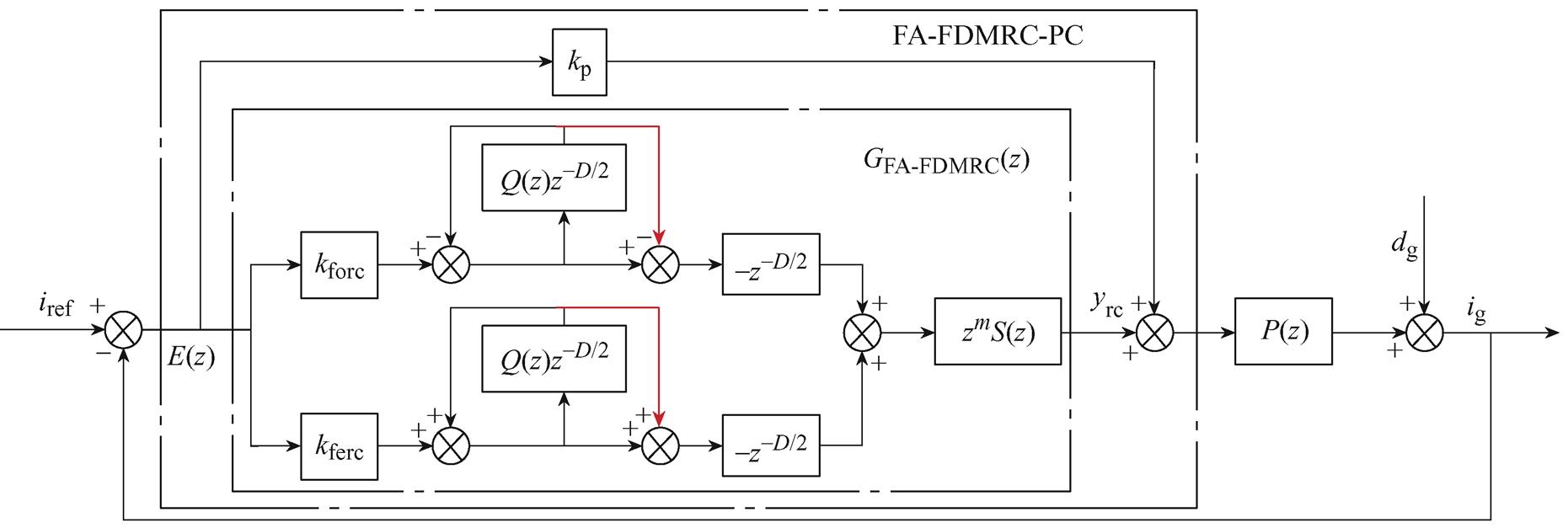
图3 FA-FDMRC-PC结构
Fig.3 Structure diagram of FA-FDMRC-PC
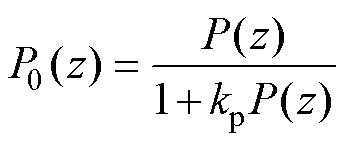 (2)
(2)
理想电网频率为50 Hz,采样频率为10 kHz时,N/2为整数。当电网频率波动时,N/2将为分数,此时将N/2改写为D/2,表示分数。本文使用IIR滤波器实现FA-FDMRC-PC,将z-D/2改写为z-(int(D/2)+d),其中int(D/2)为整数部分,d为使用IIR滤波器实现的分数部分。K阶IIR滤波器结构如图4所示。K阶IIR滤波器需要满足d>K-1,z-d可表示为
 (3)
(3)
其中
 (4)
(4)
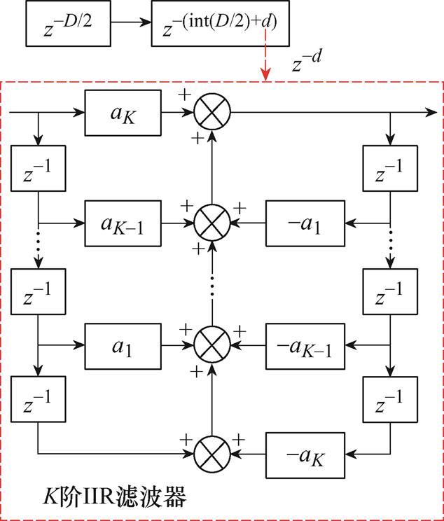
图4 K阶IIR滤波器结构
Fig.4 Structure diagram of K-order IIR filter
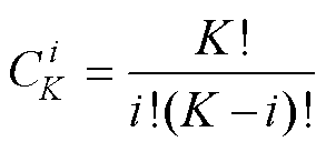 (5)
(5)
FA-FDMRC的传递函数由式(1)改写为
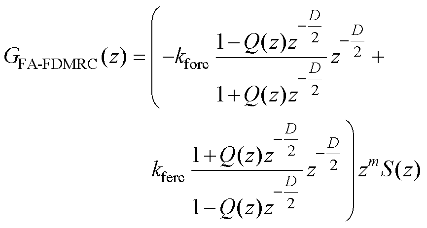 (6)
(6)
其中
D/2=int(D/2)+d
由图3可得系统误差为
 (7)
(7)
此时系统特征方程为
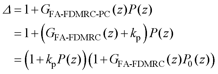 (8)
(8)
通过特征方程可得到两个稳定条件:①1+kpP(z)=0的根在单位圆内;②|1+GFA-FDMRC(z)P0(z)|≠0。
将式(6)代入条件②可得
 (9)
(9)
式中,Qz=Q(z)z-D/2;PSz=zmS(z)P(z)。为方便计算,令kforc=kferc= kfrc,满足式(9)需要得
 (10)
(10)
由文献[29]可知,若参考信号和扰动信号的频率为基波频率的整数倍,则|z-D|=1,可得
 (11)
(11)
通过频率特性可得P0(jw)=NP(w)exp(jqP(w)),其中,NP(w)和qP(w)分别为P0幅频特性和相频特性,同理,S(jw)=NS(w)exp(jqS(w)),NS(w)和θS(w)分别为S的幅频特性和相频特性。因此可得
 (12)
(12)
由欧拉公式可得
 (13)
(13)
由于kfrc>0、NP(w)>0、NS(w)>0,因此
 (14)
(14)
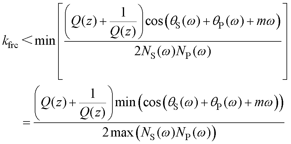 (15)
(15)
由此可知,需要根据式(14)和式(15)选取zm和kfrc,系统才能稳定。
本文在单相LCL型并网逆变器中证明频率自适应前馈双模重复-比例控制的谐波抑制能力和动态性能。LCL型并网逆变器模型如图5所示。图5中,L1为逆变器侧滤波电感,L2为电网侧滤波电感,C为滤波电容,Ed为直流母线电压,uinv为逆变器输出电压,ig为并网电流,ug为电网电压,iC为电容电流。锁相环PLL采集电网公共耦合点(Point of Common Coupling, PCC)电压的相位,与参考电流Iref的幅值构成参考电流iref,Gi(z)为电流控制器,即为FA-FDMRC-PC控制器,ZOH为零阶保持器。LCL型滤波器的等效传递函数为
 (16)
(16)
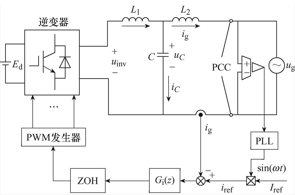
图5 LCL型并网逆变器模型
Fig.5 LCL-type grid-connected inverter model
在数字控制中,数字控制延迟的影响不可忽略,考虑数字控制延迟的s域模型如图6所示。图6中,dg(s)为扰动信号,Ts为采样周期, 为数字控制引入的单周期采样计算延迟,Gh(s)为零阶保持器引起的PWM延迟,表达式为
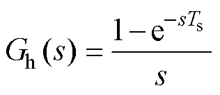 (17)
(17)

图6 LCL型并网逆变器数字控制结构
Fig.6 Block diagram of the digital control LCL-type grid-connected inverter model
由文献[21]可知,式(17)可简化为
 (18)
(18)
因此,PWM延迟为1/2周期,与单周期采样计算延迟共同作用,系统的数字控制延迟为1.5个周期。因此,考虑数字控制延迟的被控对象的传递函数为
 (19)
(19)
单相LCL型并网逆变器参数见表2。根据表2中的参数可得
 (20)
(20)
表2 单相LCL型并网逆变器参数
Tab.2 LCL-type grid-connected inverter parameters
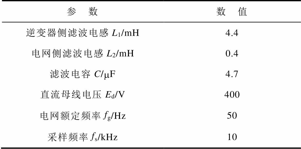
参 数数 值 逆变器侧滤波电感L1/mH4.4 电网侧滤波电感L2/mH0.4 滤波电容C/mF4.7 直流母线电压Ed/V400 电网额定频率fg/Hz50 采样频率fs/kHz10
由式(8)可知,比例增益kp影响系统特征方程,对系统的稳定性有很大影响。满足稳定条件①可等价于满足P0(z)的所有极点都在单位圆内。kp取值为8~12时,P0(z)的极点分布和伯德图如图7、图8所示。由图7可知,此时P0(z)的极点都在单位圆内,满足条件①。由图8可知,P0(z)在低频段的幅频响应曲线几乎为常数,即频率特性为理想的被控对象频率特性。
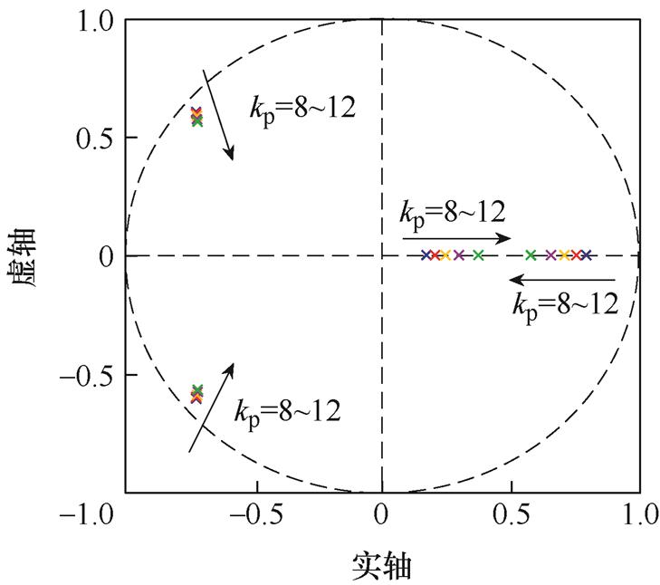
图7 不同kp下P0(z)的极点分布
Fig.7 The distribution of poles of P0(z) with different kp
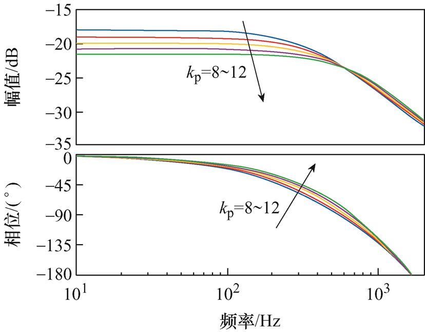
图8 不同kp下P0(z)的伯德图
Fig.8 Bode plots of P0(z) with different kp
理想内模滤波器Q(z)=1,但会导致系统不稳定。因此,Q(z)一般为低通滤波器或小于1的常数。采用低通滤波器时内模滤波器的表达式为
 (21)
(21)
Q(z)=(z+2+z-1)/4和Q(z)=0.97时的伯德图如图9所示,由图可知,Q(z)=(z+2+z-1)/4时,前馈双模重复控制在低频段内的谐振频率处所能提供的开环增益更高,且在高频段内增益衰减,使控制器在无误差跟踪输入信号的同时,能有效消除低次谐波。
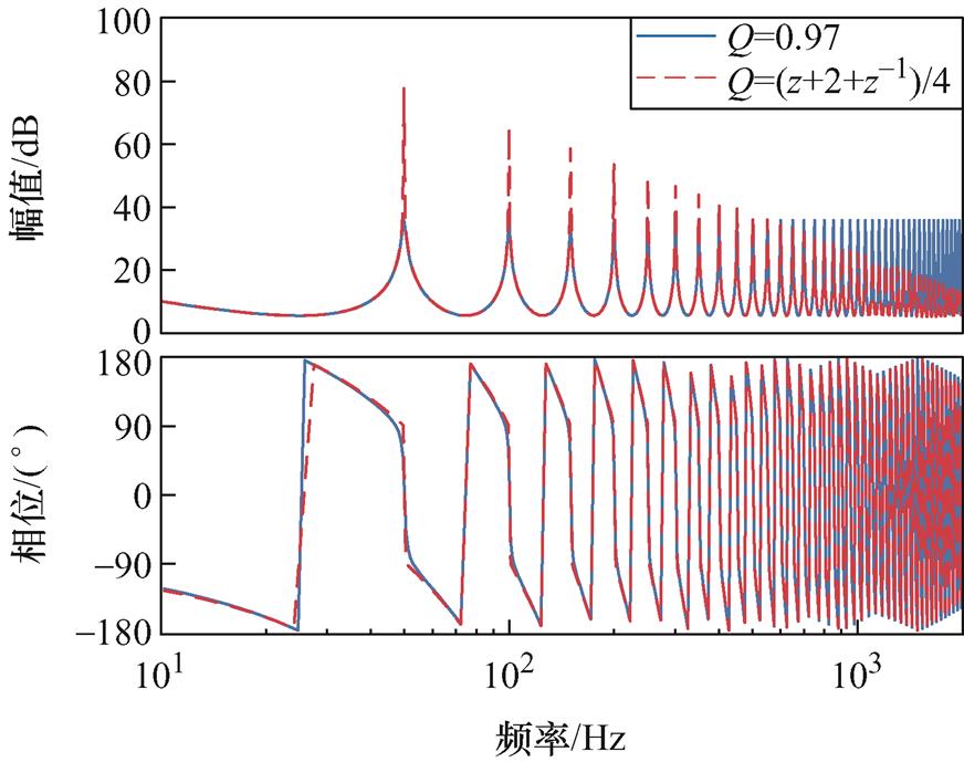
图9 Q(z)=(z+2+z-1)/4和Q(z)=0.97的伯德图
Fig.9 Bode plots of Q(z)=(z+2+z-1)/4 and Q(z)=0.97
由于系统的主要低频谐波频率在20次谐波频率以下,因此滤波器的截止频率选择为1 kHz,而巴特沃斯低通滤波器的过渡带比二阶低通滤波器窄,因此选取截止频率为1 kHz的4阶巴特沃斯低通滤波器,其传递函数为
 (22)
(22)
加入S(z)后系统伯德图如图10所示。由图10可知,系统的高频衰减能力进一步提高。
由式(14)可知,补偿后被控对象的相位在低频段应在±90°内。由图10可知,补偿后的被控对象明显不满足稳定条件,因此需要相位补偿。当m=5~11时,qS(w)+qP(w)+mw 的相频特性曲线如图11所示。由图11可知,m=9时,qS(w)+qP(q)+mw的相位最接近0°,符合理想稳定状态的相位要求。
由图10可得,max(NS(w)NP(w))=0.1,由图11可得,min[cos(qS(w)+qP(w)+mw)]=0.96,代入式(15)可得重复控制增益kfrc的最大值为9。根据稳定条件②,设H(ejwt)=Q2(z)[1-2kfrc(1/Q(z))zmS(z)P0(z)],若H(ejwt)的奈奎斯特曲线在单位圆内,则说明系统稳定。kfrc的值从6变化至9对应的H(ejwt)的奈奎斯特曲线如图12所示。由图12可知,kfrc=7时系统稳定,且奈奎斯特曲线更接近圆心,即系统有更好的信号跟踪能力。由于在单相并网逆变器中奇次谐波含量大于偶次谐波,因此选择kforc=4,kferc=3。
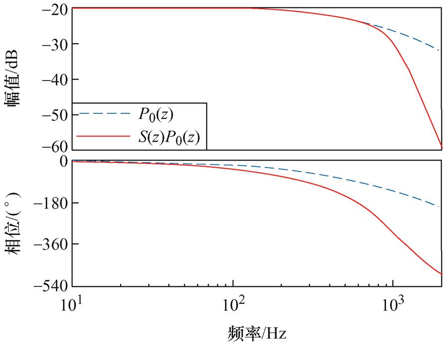
图10 S(z)P0(z)和P0(z)伯德图
Fig.10 Bode plots of S(z)P0(z) and P0(z)
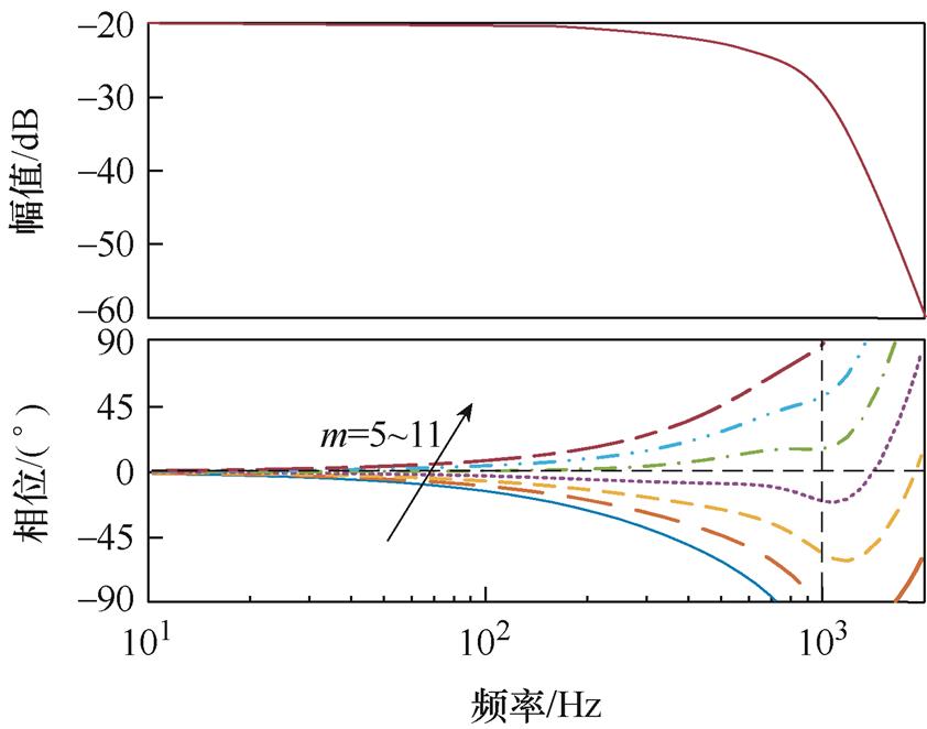
图11 不同m时qS(w)+qP(w)+mw 的伯德图
Fig.11 Bode plots of qS(w)+qP(ω)+mw with different m
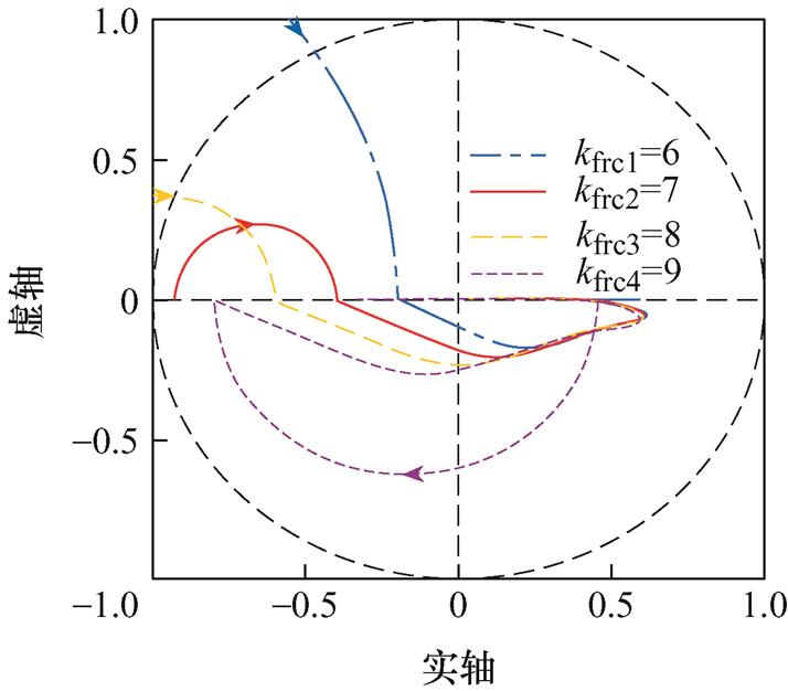
图12 不同kfrc时H(ejwt)的奈奎斯特曲线
Fig.12 Nyquist plots of H(ejwt) with different kfrc
为了验证所提出方案的有效性及可行性,搭建了单相LCL型并网逆变器实验平台,如图13所示。图13中,直流电源为Chroma 62150H-1000,逆变器平台为研旭YXPHM-TP3xb-I,交流电源为Chroma 61815,示波器为Tex TBS2204B,电能质量分析仪为Fluke 1775。实验参数见表2。
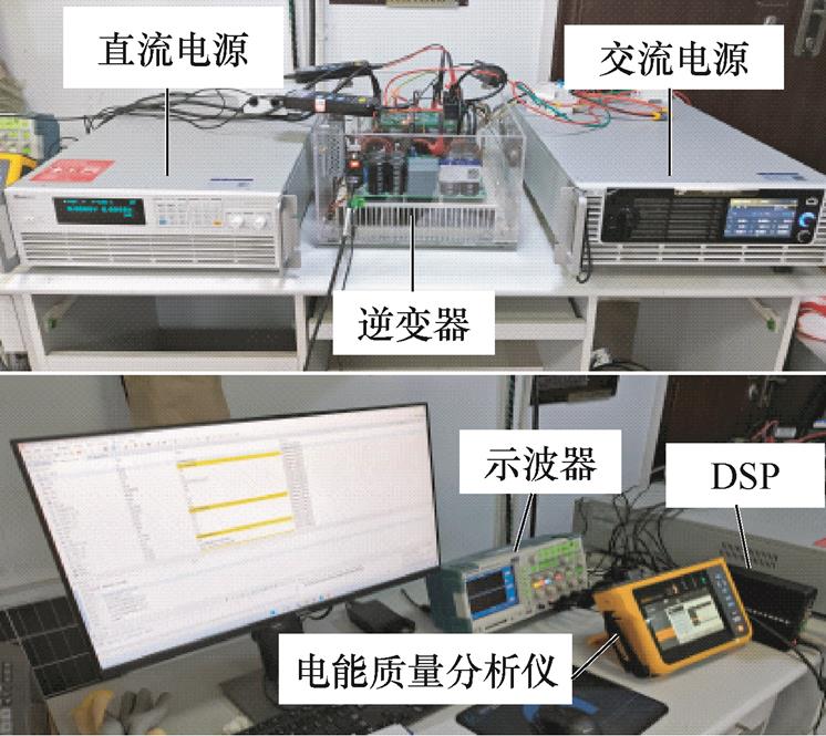
图13 LCL型并网逆变器实验平台
Fig.13 LCL-type grid-connected inverter experimental platform
在电网频率50 Hz的情况下对比了RC-PC和FA-FDMRC-PC,从而验证所提出的控制方法在理想电网下的谐波抑制能力和动态性能。电网频率波动时,以电网频率49.6 Hz和50.4 Hz为例,对比FDMRC-PC和FA-FDMRC-PC两种控制策略在电网频率波动时的谐波抑制能力和动态性能。为了模拟真实电网环境,在电网中加入THD=5.7%的电网背景谐波,其频谱如图14所示。
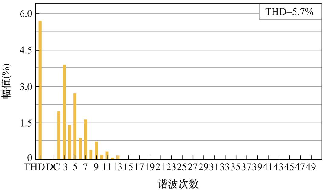
图14 电网背景谐波频谱
Fig.14 Grid background harmonic spectrum
电网频率为50 Hz时,FA-FDMRC-PC和FDMRC-PC的实验结果一致。RC-PC的并网电流波形及其频谱分别如图15、图16所示。FA-FDMRC-PC的并网电流波形及其频谱分别如图17、图18所示,由图16、图18可知,RC-PC及FA-FDMRC-PC的并网电流THD分别为1.5%,1.0%。为了验证FA- FDMRC-PC的动态性能,在实验中将参考电流幅值由5 A突变至10 A,该过程中RC-PC和FA- FDMRC-PC的并网电流波形分别如图19、图20所示。当参考电流幅值突变后,FA-FDMRC-PC的并网电流在2个周期内稳定,优于RC-PC。图15~图20说明FA-FDMRC-PC在电网频率50 Hz时具有较好的谐波抑制能力和动态性能。
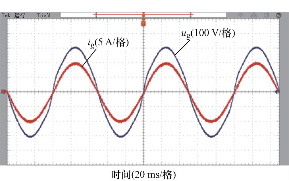
图15 fg=50 Hz时,RC-PC的并网电流
Fig.15 When fg=50 Hz, ig of RC-PC
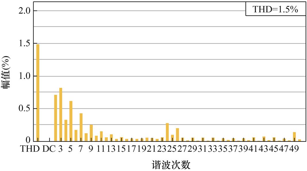
图16 fg=50 Hz时,RC-PC的并网电流频谱
Fig.16 When fg=50 Hz, current spectrum of RC-PC
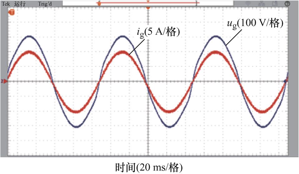
图17 fg=50 Hz时,FA-FDMRC-PC的并网电流
Fig.17 When fg=50 Hz, igof FA-FDMRC-PC
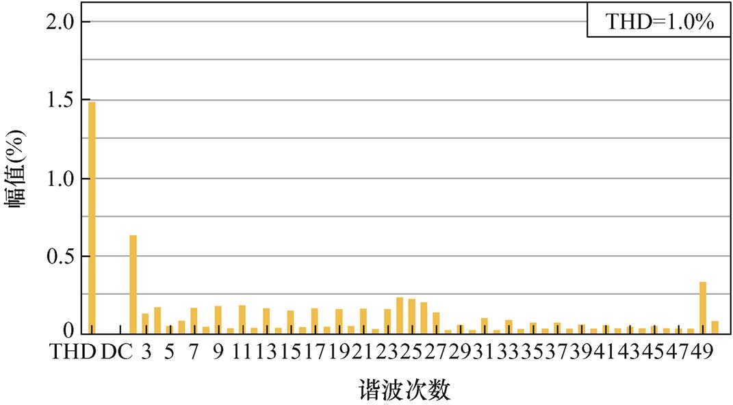
图18 fg=50 Hz时,FA-FDMRC-PC的并网电流频谱
Fig.18 When fg=50 Hz, current spectrum of FA-FDMRC-PC
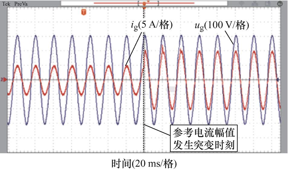
图19 fg=50 Hz时,参考电流突变前后RC-PC并网电流
Fig.19 When fg=50 Hz, ig of RC-PC before and after the reference current mutation
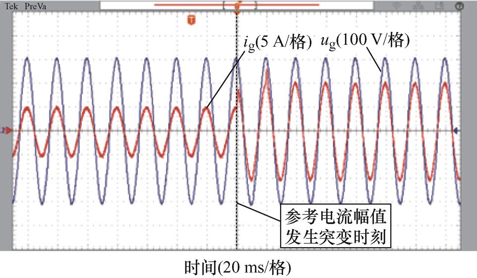
图20 fg=50 Hz时,参考电流突变前后FA-FDMRC-PC并网电流
Fig.20 When fg=50 Hz, ig of FA-FDMRC-PC before and after the reference current mutation
电网频率为49.6 Hz时,FDMRC-PC的并网电流波形及其频谱如图21、图22所示,由图22可知,并网电流THD升高至1.6%。FA-FDMRC-PC的并网电流波形及其频谱如图23、图24所示,并网电流THD仅为0.8%。参考电流幅值从5 A突变至10 A前后FDMRC-PC和FA-FDMRC-PC的并网电流波形分别如图25、图26所示,当参考电流幅值突变后,FA-FDMRC-PC的并网电流在2个周期内稳定。图21~图26说明FA-FDMRC-PC在电网频率为49.6 Hz时仍具有较好的谐波抑制能力和动态性能。
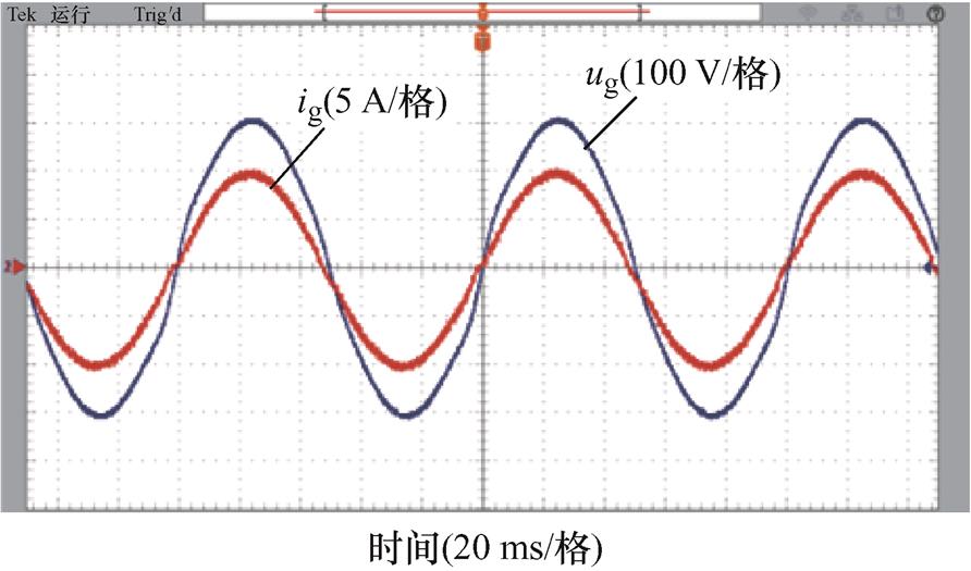
图21 fg=49.6 Hz时,FDMRC-PC的并网电流
Fig.21 When fg=49.6 Hz, ig of FDMRC-PC
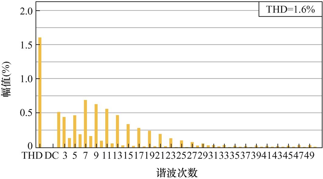
图22 fg=49.6 Hz时,FDMRC-PC的并网电流频谱
Fig.22 When fg=49.6 Hz, current spectrum of FDMRC-PC
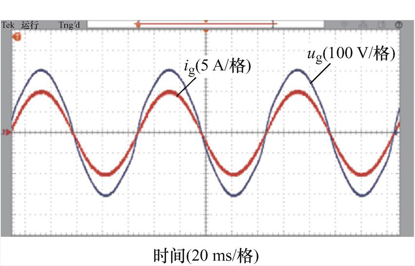
图23 fg=49.6 Hz时,FA-FDMRC-PC的并网电流
Fig.23 When fg=49.6 Hz, ig of FA-FDMRC-PC
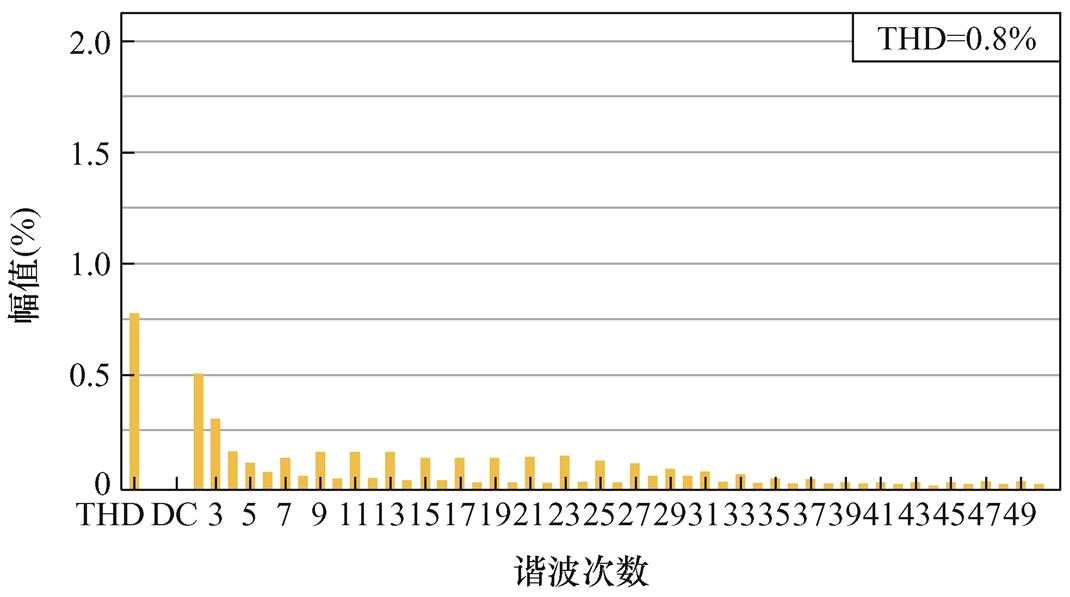
图24 fg=49.6 Hz时,FA-FDMRC-PC的并网电流频谱
Fig.24 When fg=49.6 Hz, current spectrum of FA-FDMRC-PC
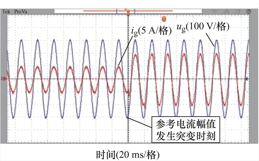
图25 fg=49.6 Hz时,参考电流突变前后FDMRC-PC并网电流
Fig.25 When fg=49.6 Hz, ig of FDMRC-PC before and after the reference current mutation
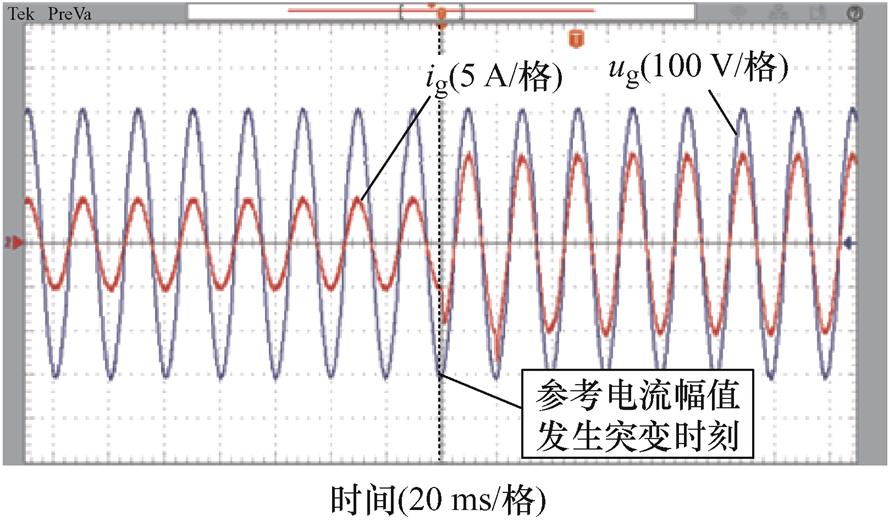
图26 fg=49.6 Hz时,参考电流突变前后FA-FDMRC-PC并网电流
Fig.26 When fg=49.6 Hz, ig of FA-FDMRC-PC before and after the reference current mutation
电网频率为50.4 Hz时,FDMRC-PC的并网电流波形及其频谱如图27、图28所示。由图28可知,并网电流THD升高至1.9%。FA-FDMRC-PC的并网电流波形及其频谱如图29、图30所示,并网电流THD仅为0.8%。参考电流幅值从5 A突变至10 A前后FDMRC- PC和FA-FDMRC-PC的并网电流波形分别如图31、图32所示,当参考电流幅值突变后,FA-FDMRC-PC的并网电流在2个周期内稳定。图27~图32说明FA-FDMRC-PC在电网频率为50.4 Hz时仍具有较好的谐波抑制能力和动态性能。
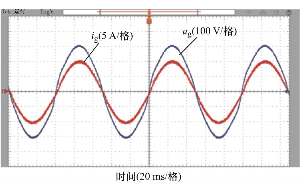
图27 fg=50.4 Hz时,FDMRC-PC的并网电流
Fig.27 When fg=50.4 Hz, ig of FDMRC-PC
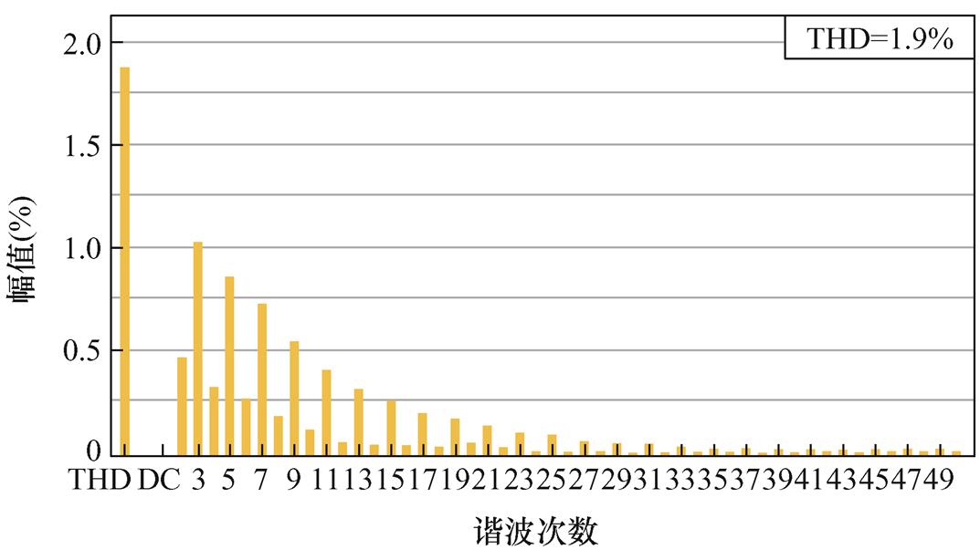
图28 fg=50.4 Hz时,FDMRC-PC的并网电流频谱
Fig.28 When fg=50.4 Hz, current spectrum of FDMRC-PC
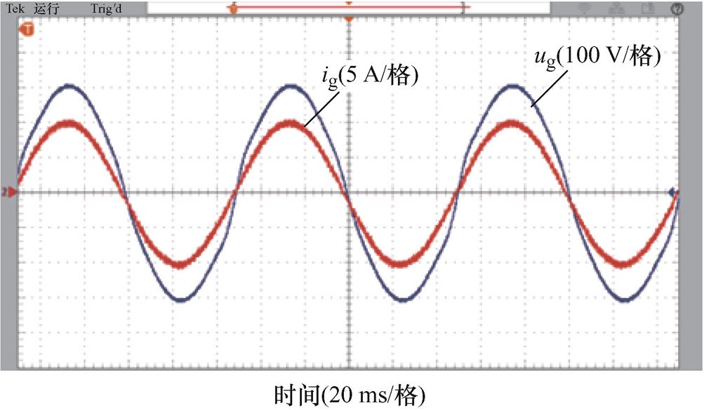
图29 fg=50.4 Hz时,FA-FDMRC-PC的并网电流
Fig.29 When fg=50.4 Hz, ig of FA-FDMRC-PC
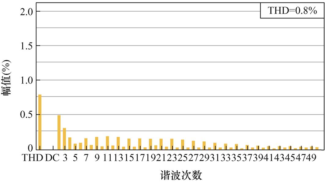
图30 fg=50.4 Hz时,FA-FDMRC-PC的并网电流频谱
Fig.30 When fg=50.4 Hz, current spectrum of FA-FDMRC-PC
为了更加清楚地对比不同电网频率下,RC-PC、FDMRC-PC和FA-FDMRC-PC的谐波抑制效果,三种控制方式下的并网电流THD如图33所示。由图33可知,当电网频率发生波动时,RC-PC和FDMRC- PC的并网电流THD不同程度升高。电网频率为49.6 Hz时,上述两种控制器的并网电流THD分别为3.8%和1.6%;电网频率为50.4 Hz时分别为3.9%和1.9%,控制器的谐波抑制能力变差。而FA- FDMRC-PC的并网电流THD仍能保持在1.5%以内,说明FA-FDMRC-PC具有频率自适应能力,能在电网波动时有效抑制逆变器并网电流谐波。
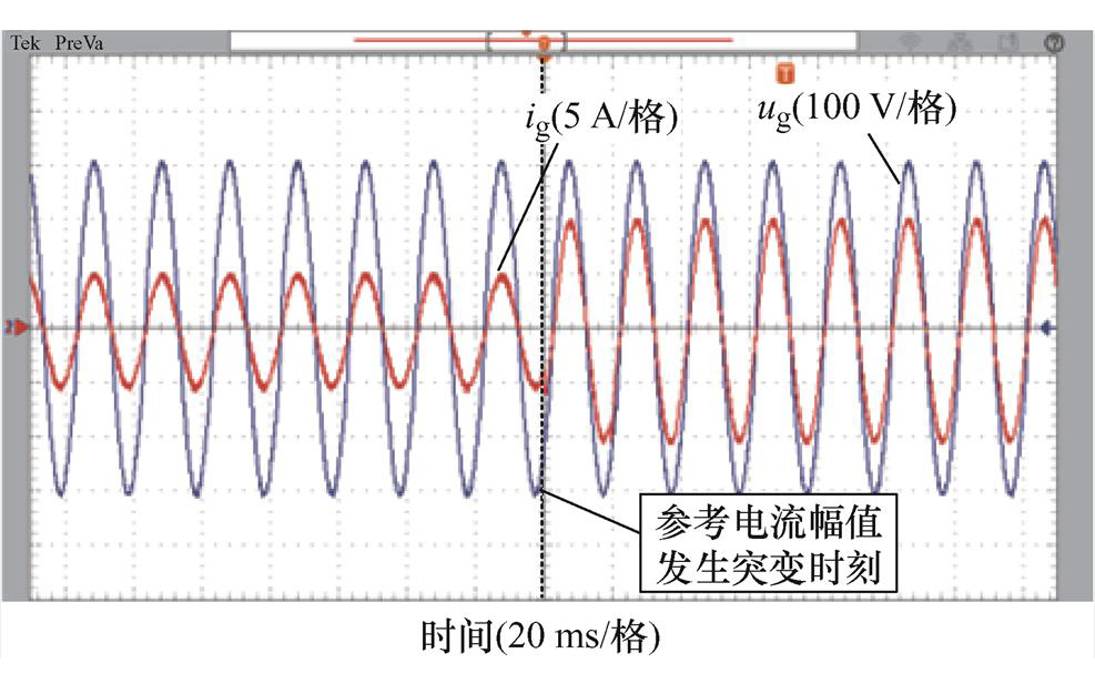
图31 fg=50.4 Hz时,参考电流突变前后FDMRC-PC并网电流
Fig.31 When fg=50.4 Hz, ig of FDMRC-PC before and after the reference current mutation
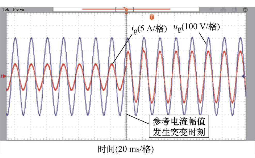
图32 fg=50.4 Hz时,参考电流突变前后FA-FDMRC-PC并网电流
Fig.32 When fg=50.4 Hz, ig of FA-FDMRC-PC before and after the reference current mutation
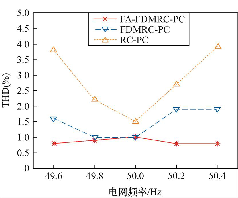
图33 不同电网频率下RC-PC、FDMRC-PC和FA-FDMRC-PC的并网电流THD
Fig.33 Current THD of RC-PC、FDMRC-PC and FA-FDMRC-PC under various grid frequencies
为了进一步验证FA-FDMRC-PC的谐波抑制能力和动态性能,在电网电压骤降的情况下,对FA- FDMRC-PC进行实验。实验中,电网电压由220 V骤降至200 V,此时FA-FDMRC-PC的并网电流波形如图34所示。由图34可知,电网电压骤降后,并网电流在1个周期内稳定,说明FA-FDMRC-PC在电网电压骤降后,仍有较好的谐波抑制能力及动态性能。
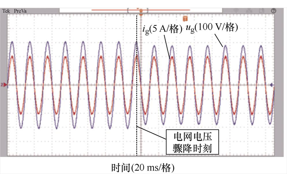
图34 电网电压骤降后FA-FDMRC-PC的并网电流
Fig.34 ig of FA-FDMRC-PC after a voltage dip in the grid
本文针对微电网下,电网频率波动造成逆变器并网电流THD升高的问题,提出了一种基于IIR滤波器的频率自适应前馈双模重复-比例控制方法。分析了该控制方法的设计机理及稳定性,以单相LCL型并网逆变器为例,给出了频率自适应前馈双模重复-比例控制的详细参数设计流程。电网频率为50 Hz时,相比RC-PC,FA-FDMRC-PC系统的并网电流THD降至1.0%,有更好的谐波抑制能力。参考电流发生突变时,过渡时间在2个基波周期内,有较好的动态性能。电网频率发生波动时,以电网频率为49.6 Hz和50.4 Hz为例,相比FDMRC-PC,FA-FDMRC-PC系统并网电流THD降至0.8%,即对电网频率波动具有自适应性,有更好的谐波抑制能力。参考电流突变时,过渡时间在2个基波周期内,有较好的动态性能。
参考文献
[1] 洪芦诚, 徐佳裕, 唐润悦, 等. 三相LCL型逆变器序阻抗简化建模方法及并网稳定性分析[J]. 电力系统自动化, 2023, 47(7): 150-157. Hong Lucheng, Xu Jiayu, Tang Runyue, et al. Simplified modeling method of sequence impedance and grid-connected stability analysis for three-phase LCL inverter[J]. Automation of Electric Power Systems, 2023, 47(7): 150-157.
[2] 王晴, 刘增, 韩鹏程, 等. 基于变流器输出阻抗的直流微电网下垂并联系统振荡机理与稳定边界分析[J]. 电工技术学报, 2023, 38(8): 2148-2161. Wang Qing, Liu Zeng, Han Pengcheng, et al. Analysis of oscillation mechanism and stability boundary of droop-controlled parallel converters based on output impedances of individual converters in DC microgrids[J]. Transactions of China Electrotechnical Society, 2023, 38(8): 2148-2161.
[3] 罗朋, 潘锦超, 洪濬哲, 等. 用于直流微电网的高升压变换器设计及效率优化[J]. 电工技术学报, 2023, 38(20): 5530-5546. Luo Peng, Pan Jinchao, Hong Junzhe, et al. Design and efficiency optimization of a high step-up converter for DC microgird[J]. Transactions of China Electrotechnical Society, 2023, 38(20): 5530-5546.
[4] 吴天昊, 谢小荣, 姜齐荣. 风电系统次同步等幅振荡的机理与特性分析[J]. 中国电机工程学报, 2023, 43(7): 2689-2699. Wu Tianhao, Xie Xiaorong, Jiang Qirong. On subsynchronous sustained oscillation issues of wind power systems[J]. Proceedings of the CSEE, 2023, 43(7): 2689-2699.
[5] 张洪亮, 张子成, 陈杰, 等. 自适应三次谐波注入的回接型LCL光伏逆变器共模谐振电流抑制方法[J]. 电工技术学报, 2023, 38(1): 220-233. Zhang Hongliang, Zhang Zicheng, Chen Jie, et al. Common-mode resonant current suppression for back-connected LCL photovoltaic inverter using adaptive third harmonic injection[J]. Transactions of China Electrotechnical Society, 2023, 38(1): 220-233.
[6] 杨权, 梁永昌, 魏建荣, 等. 多谐波源下分布式电源并网逆变器的谐波抑制策略[J]. 电工技术学报, 2023, 38(11): 2908-2920. Yang Quan, Liang Yongchang, Wei Jianrong, et al. Research on harmonic suppression strategy of grid connected inverter under multi-harmonic sources[J]. Transactions of China Electrotechnical Society, 2023, 38(11): 2908-2920.
[7] 芮涛, 尹政, 汪凤翔, 等. 基于双矢量的并网逆变器无模型预测电流控制策略[J]. 电工技术学报, 2023, 38(14): 3759-3768. Rui Tao, Yin Zheng, Wang Fengxiang, et al. Model-free predictive current control strategy of grid-connected inverter based on double-vector[J]. Transactions of China Electrotechnical Society, 2023, 38(14): 3759-3768.
[8] 李文番, 张国钢, 钟浩杰, 等. 一种高频率分辨率的谐波、间谐波分析模型[J]. 电工技术学报, 2022, 37(13): 3372-3379, 3403. Li Wenfan, Zhang Guogang, Zhong Haojie, et al. A high frequency resolution harmonic and inter- harmonic analysis model[J]. Transactions of China Electrotechnical Society, 2022, 37(13): 3372-3379, 3403.
[9] 李勇, 刘珮瑶, 胡斯佳, 等. 基于感应滤波的光伏电站谐波谐振抑制方法[J]. 电工技术学报, 2022, 37(15): 3781-3793.Li Yong, Liu Peiyao, Hu Sijia, et al. Harmonic resonance damping method of photovoltaic power station based on inductive filtering[J]. Transactions of China Electrotechnical Society, 2022, 37(15): 3781-3793.
[10] IEEE standard for harmonic control in electric power systems: IEEE Std 519-2022[S]. Institute of Electrical and Electronics Engineers, 2022.
[11] 国家市场监督管理总局, 国家标准化管理委员会. 光伏发电并网逆变器技术要求: GB/T 37408-2019[S]. 北京: 中国标准出版社, 2019.
[12] 兰梓冉, 郝瑞祥, 角宏林, 等. 基于重复控制和状态反馈的三相逆变器最优预见控制[J]. 电工技术学报, 2022, 37(6): 1473-1481. Lan Ziran, Hao Ruixiang, Jiao Honglin, et al. Optimal preview control of three-phase inverter based on repetitive control and state-feedback[J]. Transactions of China Electrotechnical Society, 2022, 37(6): 1473- 1481.
[13] He Liqun, Zhang Kai, Xiong Jian, et al. A repetitive control scheme for harmonic suppression of circulating current in modular multilevel converters[J]. IEEE Transactions on Power Electronics, 2015, 30(1): 471-481.
[14] Wu Xinhui, Panda S K, Xu Jianxin. Design of a plug-in repetitive control scheme for eliminating supply-side current harmonics of three-phase PWM boost rectifiers under generalized supply voltage conditions[J]. IEEE Transactions on Power Elec- tronics, 2010, 25(7): 1800-1810.
[15] 张旗, 蔡逢煌, 黄丽梅, 等. 单相程控电流源PI+ 重复控制[J]. 电工技术学报, 2019, 34(增刊1): 163- 170.Zhang Qi, Cai Fenghuang, Huang Limei, et al. PI+ repetitive control of single-phase programmable current source[J]. Transactions of China Electrotechnical Society, 2019, 34(S1): 163-170.
[16] 李鑫, 孟亨, 杨桢, 等. 基于BP神经网络递推积分PI-重复控制在微电网APF中的研究[J]. 电力系统保护与控制, 2019, 47(6): 132-140. Li Xin, Meng Heng, Yang Zhen, et al. Research on recursive integral PI-repetitive control based on BP neural network in micro-grid APF[J]. Power System Protection and Control, 2019, 47(6): 132-140.
[17] 宫金武, 查晓明, 陈佰锋. 一种快速重复控制策略在APF中的实现和分析[J]. 电工技术学报, 2011, 26(10): 110-117. Gong Jinwu, Zha Xiaoming, Chen Baifeng. Analysis and realization of a fast repetitive controller in active power filter system[J]. Transactions of China Electrotechnical Society, 2011, 26(10): 110-117.
[18] 王吉彪, 陈启宏, 张立炎, 等. 基于内模原理的并网逆变器双模PI控制[J]. 电工技术学报, 2018, 33(23): 5484-5495. Wang Jibiao, Chen Qihong, Zhang Liyan, et al. Internal model principle based dual-mode PI control for grid-tied inverters[J]. Transactions of China Electrotechnical Society, 2018, 33(23): 5484-5495.
[19] Zhao Qiangsong, Ye Yongqiang. A PIMR-type repetitive control for a grid-tied inverter: structure, analysis, and design[J]. IEEE Transactions on Power Electronics, 2018, 33(3): 2730-2739.
[20] 赵强松, 陈莎莎, 周晓宇, 等. 用于并网逆变器谐波抑制的重复-比例复合控制器分析与设计[J]. 电工技术学报, 2019, 34(24): 5189-5198. Zhao Qiangsong, Chen Shasha, Zhou Xiaoyu, et al. Analysis and design of combination controller based on repetitive control and proportional control for harmonics suppression of grid-tied inverters[J]. Transactions of China Electrotechnical Society, 2019, 34(24): 5189-5198.
[21] Chen Sainan, Zhao Qiangsong, Ye Yongqiang, et al. Using IIR filter in fractional order phase lead compensation PIMR-RC for grid-tied inverters[J]. IEEE Transactions on Industrial Electronics, 2023, 70(9): 9399-9409.
[22] Zhou Keliang, Wang Danwei, Zhang Bin. Dual mode structure repetitive control of CVCF PWM inverters[C]// 2009 IEEE 6th International Power Electronics and Motion Control Conference, Wuhan, China, 2009: 1524-1526.
[23] 邹志翔, 王政, 程明, 等. 双模结构重复控制器在单相并联有源滤波器中的应用[J]. 中国电机工程学报, 2013, 33(36): 88-95, 13.Zou Zhixiang, Wang Zheng, Cheng Ming, et al. A hybrid current regulation scheme for single-phase active power filters based on dual-mode structure repetitive control[J]. Proceedings of the CSEE, 2013, 33(36): 88-95, 13.
[24] Cui Peiling, Wang Qirui, Zhang Guoxi, et al. Hybrid fractional repetitive control for magnetically suspended rotor systems[J]. IEEE Transactions on Industrial Electronics, 2018, 65(4): 3491-3498.
[25] Zhu Mingzhe, Ye Yongqiang, Xiong Yongkang, et al. Multibandwidth repetitive control resisting frequency variation in grid-tied inverters[J]. IEEE Journal of Emerging and Selected Topics in Power Electronics, 2022, 10(1): 446-454.
[26] Kurniawan E, Cao Zhenwei, Man Zhihong. Design of robust repetitive control with time-varying sampling periods[J]. IEEE Transactions on Industrial Elec- tronics, 2014, 61(6): 2834-2841.
[27] Zhao Qiangsong, Chen Sainan, Wen Shengjun, et al. A frequency adaptive PIMR-type repetitive control for a grid-tied inverter[J]. IEEE Access, 2018, 6: 65418-65428.
[28] Chen Yuxuan, Zhou Keliang, Tang Chao, et al. Fractional-order multiperiodic odd-harmonic repetitive control of programmable AC power sources[J]. IEEE Transactions on Power Electronics, 2022, 37(7): 7751-7758.
[29] 赵强松. 新型比例积分多谐振控制及其并网逆变器应用研究[D]. 南京: 南京航空航天大学, 2016.
Zhao Qiangsong. Research on novel proportional integral multi-resonant control scheme and its application in grid-connected inverters[D]. Nanjing: Nanjing University of Aeronautics and Astronautics, 2016.
[30] Ye Jie, Liu Linguo, Xu Jinbang, et al. Frequency adaptive proportional-repetitive control for grid- connected inverters[J]. IEEE Transactions on Industrial Electronics, 2021, 68(9): 7965-7974.
[31] Zhao Qiangsong, Zhang Hongwei, Gao Yang, et al. Novel fractional-order repetitive controller based on thiran IIR filter for grid-connected inverters[J]. IEEE Access, 2015, 10: 82015-82024.
Abstract Repetitive control (RC) based on the internal model principle can achieve zero tracking error for periodic reference and disturbance in a steady state. It has been widely used in grid-connected inverters to improve the current control performance. Owing to a recursive form and an inherent delay of one fundamental period in the internal model, the RC has a relatively slow transient response. At the same time, grid frequency fluctuations in the microgrid lead to the higher harmonic content of the inverter grid current. Therefore, this paper proposes the frequency adaptive feedforward dual-mode repetitive control and proportional control (FA-FDMRC-PC) scheme for grid-connected inverters in the microgrid to track the fundamental reference signal and suppress the harmonic signals simultaneously.
First, the principle of feedforward dual-mode repetitive control (FDMRC) is analyzed. The feedforward links are added to the internal models of the dual-mode repetitive control (DMRC) to improve the dynamic performance of the system. From the open-loop bode plots of FDMRC, DMRC, and RC, it can be seen that the FDMRC has much larger open-loop gains at the frequencies of interest with better harmonic suppression capability. Then, the FA-FDMRC-PC scheme is proposed, which connects the FDMRC and the proportional control in parallel to form the feedforward dual-mode repetitive control and proportional control (FDMRC-PC), further improving the dynamic performance of the system and realizing the fractional delay through the infinite impulse response (IIR) filter. The stability analysis provides the relevant stability conditions, which are then utilized in designing the proportional gain, internal mode filter, compensator, phase lead compensator, and repetitive control gain.
Subsequently, a single-phase LCL-type grid-connected inverter experimental platform is set up. The controller based on repetitive control and proportional control (RC-PC) and FA-FDMRC-PC are compared at the grid frequency of 50 Hz to verify the harmonics suppression capability and dynamic performance of the proposed control scheme under the ideal grid. The total harmonic distortion (THD) of the grid current of the proposed FA-FDMRC-PC is 1.0%. However, for the RC-PC, the THD value is 1.5%, higher than the THD of the FA-FDMRC-PC. To verify the dynamic performance of the FA-FDMRC-PC, output current waveforms are recorded and analyzed when the peak value of the reference current is changed from 5 A to 10 A. The waveform of the grid current tends to be stable after about two cycles for the FA-FDMRC-PC when the reference current changes abruptly, which shows that the proposed FA-FDMRC-PC has a faster transient response than the RC-PC. When the grid frequency is 49.6 Hz, the THD of the FA-FDMRC-PC is only 0.8%, but the THD of the FDMRC-PC rises to 1.6%. When the grid frequency is 50.4 Hz, the THD of the FA-FDMRC-PC is only 0.8%, but the THD of the FDMRC-PC rises to 1.9%. When the grid frequencies are 49.6 Hz and 50.4 Hz, the waveforms of the grid current tend to be stable after about two cycles for the FA-FDMRC-PC when the peak value of the reference current is changed from 5 A to 10 A.
Experimental results verify that the proposed FA-FDMRC-PC scheme has a better immunity to grid frequency fluctuation and a faster dynamic response when the grid frequency fluctuates.
keywords:Microgrid,repetitive control, grid-connected inverter, frequency adaptive, infinite impulse response filter
DOI:10.19595/j.cnki.1000-6753.tces.231947
中图分类号:TM464
国家自然科学基金(61973157, 62073297)、河南省自然科学基金(232300421239)和河南省重点研发计划专项(231111221600)资助项目。
收稿日期 2023-11-21
改稿日期 2024-01-10
赵强松 男,1982年生,博士,副教授,研究方向为电力电子系统建模及控制、重复控制技术及应用。E-mail: zhaoqiangsong@126.com(通信作者)
陈 昊 男,1999年生,硕士研究生,研究方向为重复控制技术。E-mail: chen_hao21@126.com
(编辑 陈 诚)