 (1)
(1)
摘要 针对永磁同步电机传统单矢量控制需遍历所有基本矢量且忽略控制稳定性的问题,该文提出基于反推控制的永磁同步电机稳定性单矢量控制策略。首先,在建立dq0坐标系下永磁同步电机数学模型的基础上,推导设计常规反推控制器;其次,根据反推控制器获取的控制电压确定最优电压矢量所在扇区,并通过数学推导证明每个扇区内必有一个稳定的基本电压矢量可供选择,提出通过基本电压矢量对应Lyapunov函数导数值两两比较的最优基本电压矢量选取方法;然后,对选取包括最优基本电压矢量在内的不同基本电压矢量时的控制性能进行对比分析;最后,对提出的控制策略进行仿真和实验验证。结果表明,在驱动恒转矩、恒惯量负载和变转矩、变惯量涡簧负载的多个场景下,该文提出的控制策略均能有效追踪参考转速,并且与传统模型预测电流控制相比,所提控制策略的稳定性更强、输出量波动更小。
关键词:永磁同步电机 反推控制 单矢量控制 基本电压矢量 功率分配
永磁同步电机(Permanent Magnet Synchronous Motor, PMSM)以其结构简单、效率高、功率密度大等特点[1],被广泛应用于电动汽车、风力发电、航空航天和机械弹性储能等领域[2-5]。PMSM传统控制方法主要包括矢量控制(Vector Control, VC)和直接转矩控制(Direct Torque Control, DTC)两大 类[6]。VC动态性能好,但需依赖复杂的坐标变换和空间矢量调制。DTC结构简洁、响应速度快,但是输出转矩脉动较大且对实时性要求较高[7]。因此,为进一步提升PMSM的控制性能,各种新型控制方法不断被提出[8-9]。
模型预测控制(Model Predivtive Control, MPC)产生于20世纪70年代,因其实现方便、易于处理各类约束而被大量应用于PMSM驱动中[10-12]。与VC不同,MPC无需坐标变换和脉宽调制,故MPC结构更加简单。与DTC相比,MPC在线优化确定最佳电压矢量,改善了矢量选择的准确率。并且,MPC还可设计实现多个控制目标,在现场中使用更加灵活。从达到的控制效果看,MPC又可分为转矩预测控制和电流预测控制(Model Predivtive Current Control, MPCC)[13-14]。因转矩和磁链量纲不同,转矩预测控制需要通过繁复的实验以合理选取权重系数。电流预测控制避免了权重设计,但每个控制周期均需要遍历所有基本矢量以确定最佳电压矢量,不便于实际应用。常见的改进方法是引入最低开关损耗原则以先确定待选矢量子集[15-16],然后在待选矢量子集中搜索出最佳电压矢量,不过在某些场合下存在可能无法找到最佳电压矢量的问题。此外,转矩预测控制和电流预测控制很难计及控制的稳定性,而稳定性是控制器设计需要考虑的基本问题。
反推控制是20世纪90年代出现的一种非线性控制方法,通过引入虚拟控制量,并结合Lyapunov函数不断递归获取真实控制量[17]。其优点之一是可用于PMSM这种多变量、强耦合的非线性系统,并能保证闭环系统的控制稳定性[4, 18]。但作为一种基于模型的控制方法,反推控制对于电机模型参数的准确性要求较高,而受环境温度、湿度、振动等因素影响,现场中获取准确模型参数的难度极大。为此,自适应反推控制被应用于PMSM控制中[19-20],通过设计对于模型参数的自适应律来辨识模型参数,以实现高精度控制。不过自适应反推控制无疑增加了算法的计算量,且自适应律设计时还需要考虑满足激励条件。
鉴于以上情况,有学者将MPC与反推控制相结合,利用反推控制来提升MPC的稳定性。如文献[21]通过量化控制Lyapunov方法选取了带有稳定性的最佳电压矢量,但是最佳电压矢量仍然需要从所有基本电压矢量中寻找,并且选择每个基本电压矢量时还需要计算Lyapunov函数的导数,算法实现较为困难,且在一定程度上仍依赖电机模型参数的准确性。文献[22]进一步设计了基于反推控制的MPC算法,给出了算法的稳定域,改善了控制性能,不过该算法也需要遍历所有基本电压矢量,并且还需要计算Lyapunov稳定性判据,实现过程仍然较为复杂。
针对上述问题,本文提出基于反推控制的PMSM稳定性单矢量控制策略。首先,建立dq0坐标系下的PMSM数学模型;其次,通过数学推导从理论上证明每个扇区内必有一个稳定的基本电压矢量可供选择;再次,借助转子位置和控制误差,通过每个扇区内三个基本电压矢量对应Lyapunov函数导数值的两两比较,取Lyapunov函数的导数最小值对应的基本电压矢量为最佳电压矢量,并将其作为开关动作依据;然后,在此基础上,对每个扇区内取不同基本电压矢量作为最佳电压矢量时的控制性能进行了对比分析;最后,通过仿真和实验验证了本文控制策略的正确性和有效性,并与其他控制方法进行了对比。结果表明,本文控制策略与反推控制的效果相差不大,比传统模型预测电流控制的稳定性更强、波动更小。
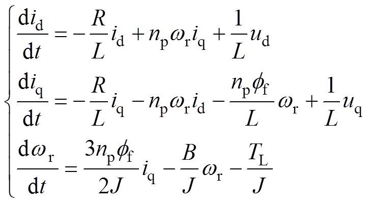
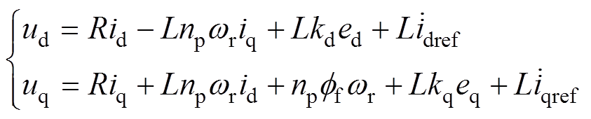
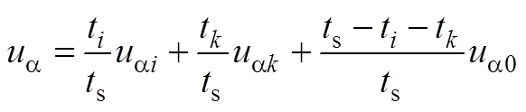
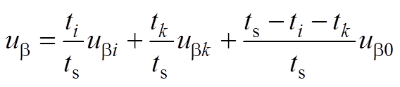
PMSM反推控制器设计是在dq0同步旋转坐标系下完成的,故以表贴式PMSM为研究对象,建立其在dq0坐标系下的数学模型[18, 23]为
(1)
式中,id、iq分别为定子电流d、q轴分量;ud、uq分别为定子电压d、q轴分量;R为定子电阻;L为定子电感;np为转子极对数; 为转子机械角速度;ff为永磁体磁链;J为转动惯量;B为黏滞摩擦系数;TL为负载转矩。
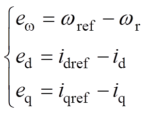
令、 和
和 的跟踪误差分别为
 、
、 和
和 ,则有
,则有
 (2)
(2)
式中, 为参考值;
为参考值; 为参考值;
为参考值; 为参考值。
为参考值。
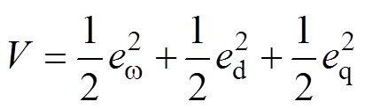
设计最终的Lyapunov函数为
 (3)
(3)
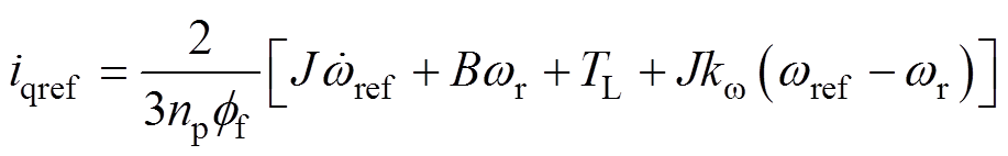
借助文献[17]中PMSM反推控制器的设计思路,省略具体的控制器推导过程,根据Lyapunov稳定性原理直接列写出其反推控制器的表达式为
 (4)
(4)
 (5)
(5)
式中, 、
、 和
和 为大于0的控制增益。
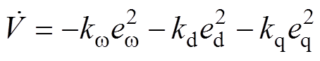
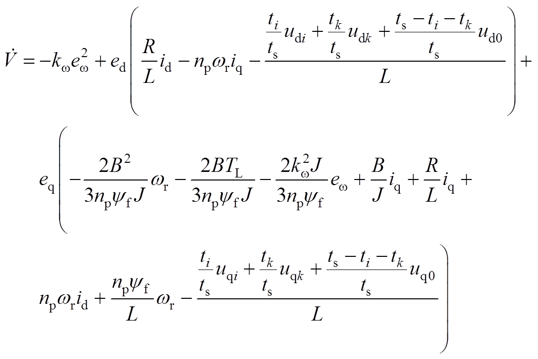
将式(4)和式(5)所示的控制器表达式代入式(1)的PMSM数学模型中,并结合式(3),可得最终Lyapunov函数的导数为
 (6)
(6)
由于Lyapunov函数V正定有界,且 ,借助Barbalat定理,可知
 (7)
(7)
由此表明,PMSM反推控制是闭环稳定的,能确保状态量渐进跟踪各自的参考值。在dq0坐标系下将控制器ud、uq设计完成后,再经过坐标反变换即可获得abc静止坐标系下的控制量。可见,PMSM反推控制算法需借助坐标变换和调制算法,且电机模型参数变化对控制性能影响较为敏感。
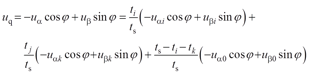
由于反推控制器是在dq0旋转坐标系下推导完成的,而PMSM控制需借助ab 静止坐标系下的电压量来选择开关矢量,故先根据ab 静止坐标系的最优矢量获取dq0坐标系下开关函数表达式,然后进一步推导证明各扇区下稳定性单矢量的存在性,并分析说明每个扇区内必有一个稳定的基本电压矢量可供选择。
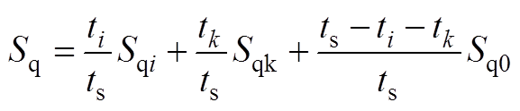
为此,首先写出ab 静止坐标系下最优电压矢量uref表达式,见附录式(A1),然后经过适当推导,可以获取dq0坐标系下开关函数Sd、Sq表达式,如式(8)所示,详细推导过程见附录。
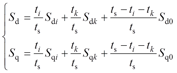 (8)
(8)
式中, 为d轴开关函数;
 为q轴开关函数;
 、、
、、 和
和 分别为开关矢量
 、
、 和
和 的d轴分量;
 、
、 和
和 分别为开关矢量、和的q轴分量;
 为一个PWM脉冲工作时间;
 为基本电压矢量
 的作用时间;
 为基本电压矢量
 的作用时间;
 为基本电压矢量
 的作用时间。
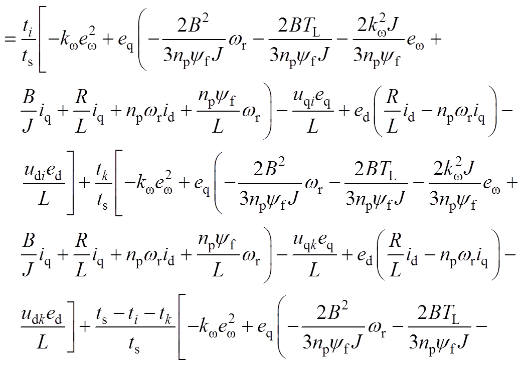
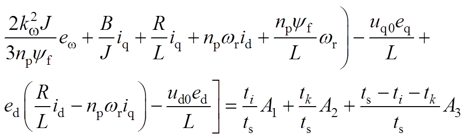
将式(8)代入式(6),并结合式(1),经过适当的推导(具体推导过程见附录第2节),可将Lyapunov函数导数改写为
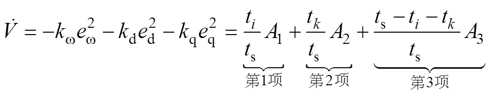 (9)
(9)
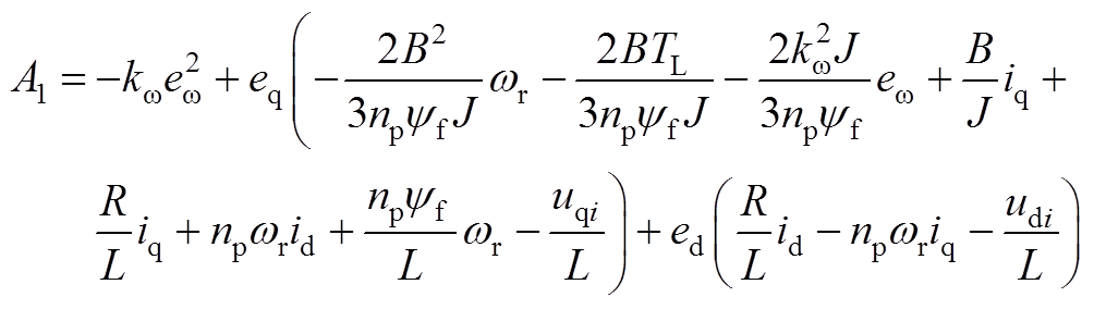
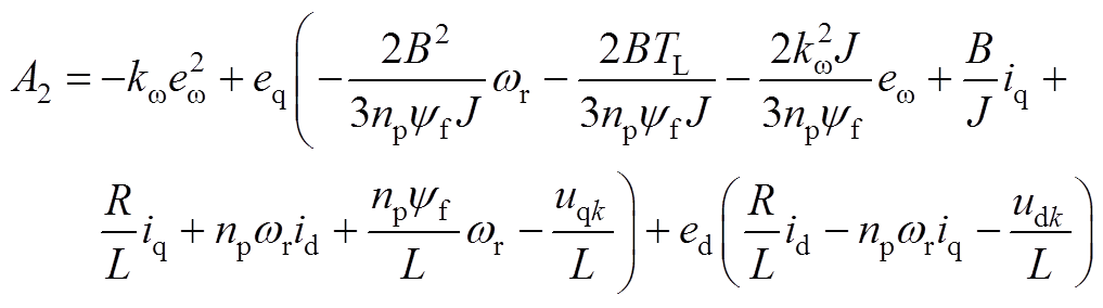
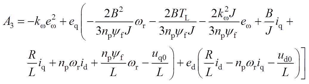
由推导可知,式(9)由三项之和组成,参数具体意义见附录第2节,其中,A1、A2和A3分别为基本电压矢量ui、uk和u0作用下的Lyapunov函数的导数,由于ti/ts、tk/ts、(ts-ti-tk)/ts均大于零,并由Lyapunov稳定性定理可知,整个式子值为非正,故第一项、第二项和第三项必有一项小于零,这表明,对于六个扇区,每个控制周期内均必有一个基本电压矢量可使控制系统保持稳定,且该基本电压矢量作用下的Lyapunov函数导数一定为负。
如何找到各扇区下这个稳定的基本电压矢量是需要解决的问题。由于通过基本电压矢量可计算获得Lyapunov函数导数,故常规思维是在每个控制周期内,分别选取研究所在扇区的三个基本电压矢量,计算其控制下的Lyapunov函数导数,然后选取导数值最小对应的基本电压矢量作为稳定性最佳基本电压矢量。但是,由附录第2节推导过程可知,Lyapunov函数导数的计算过程较为复杂,且传统方法还需要计算三次Lyapunov函数的导数。此外,Lyapunov函数导数还高度依赖电机的模型参数,可见,选取稳定性基本电压矢量的常规处理方法过程极为繁琐,计算量也较大。为此,本文将提出一种更加简单、快捷的最佳电压矢量选取方法。
当反推控制器输出d、q轴电压后,通过Clarke反变换得到ab 坐标系下的电压量,即可进行扇区选择,选定扇区N之后,就需确定控制策略以选择合理的开关输入。
由于第2节已证明,必有一个基本电压矢量的Lyapunov函数的导数为负,故本文提出的稳定性单矢量控制策略为:对选取扇区内三个基本电压矢量对应Lyapunov函数的导数进行两两比较,选出Lyapunov函数导数的最小值对应的基本电压矢量即为该最优基本电压矢量,然后可根据选择的最优控制矢量决定开关状态。
将基本电压矢量ui、uk、u0作用下的Lyapunov函数分别写为Vi、Vk、V0,将Vi、Vk、V0的导数两两做差,并结合式(9),可得
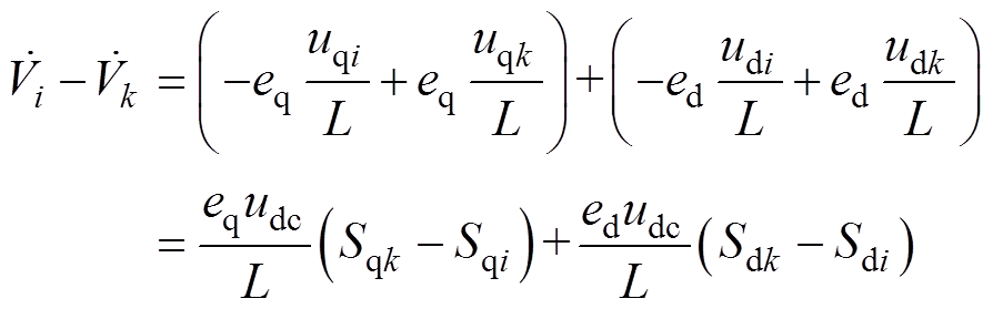 (10)
(10)
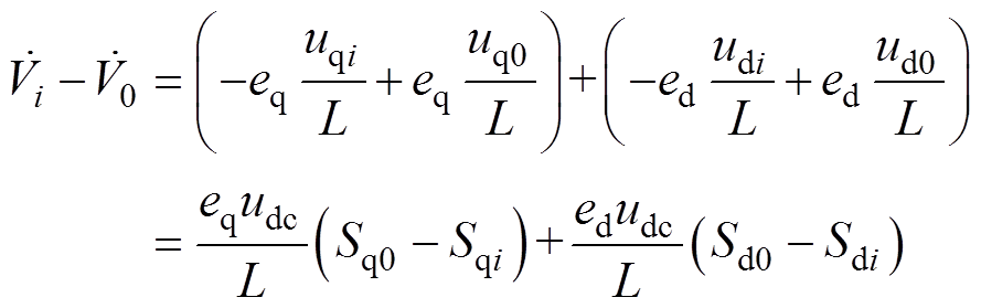 (11)
(11)
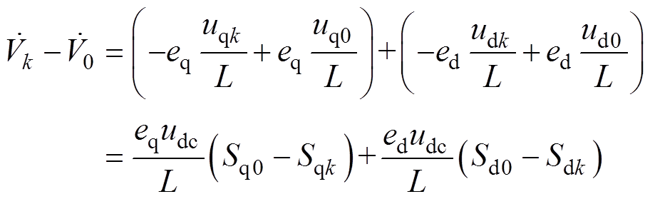 (12)
(12)
式中, 为直流侧电容电压;
 、
、 和
和 分别为基本电压矢量、和的d轴分量;
 、
、 和
和 分别为基本电压矢量、和的q轴分量。
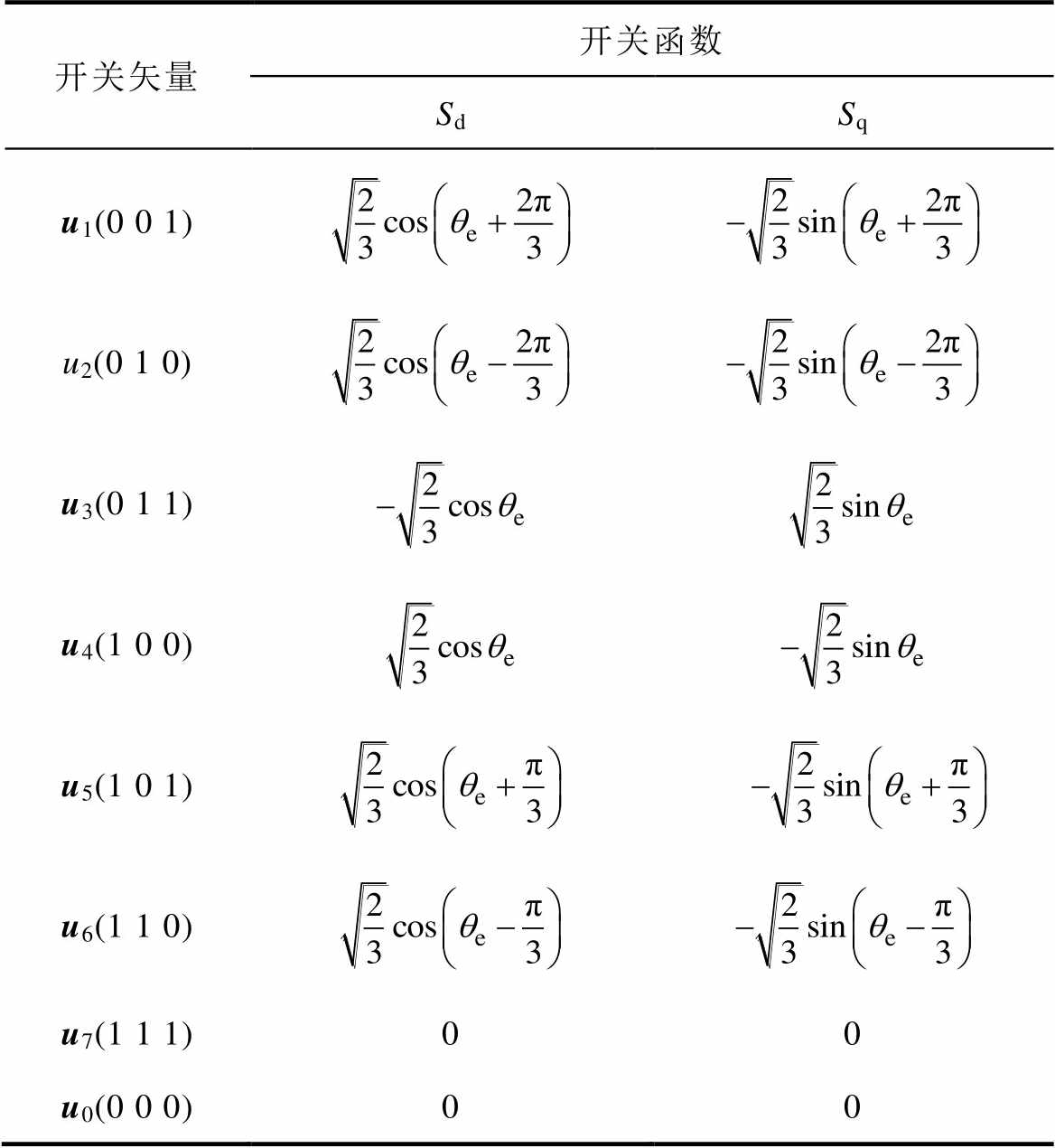
表1给出了八个基本电压矢量对应dq0坐标系下的开关函数取值[24]。表中, 为转子位置角,由表1可知,开关函数只与转子位置相关。由于udc、L一定大于零,仅需获取误差变量eq、ed以及转子位置角度,根据式(10)~式(12)进行简单计算比较,即可快速选取具备稳定性的最佳基本电压矢量。
表1 dq0坐标系下基本矢量的开关函数取值
Tab.1 Switch function value for basic vector in dq0 coordinate system
开关矢量开关函数 SdSq u1(0 0 1) u2(0 1 0) u3(0 1 1) u4(1 0 0) u5(1 0 1) u6(1 1 0) u7(1 1 1)00 u0(0 0 0)00
在经过必要的推导和计算后,表2给出了六个扇区中各自三个基本电压矢量作用下Lyapunov函数的导数差值,据此,可根据该表编制策略表,实现最佳基本电压矢量的选择。可见,本文提出的矢量选择方法与电机结构参数无关,只取决于转子位置和误差变量。
表2 Lyapunov函数的导数差
Tab.2 Differences in derivatives of the Lyapunov function
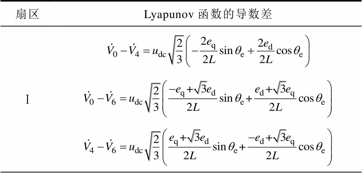
扇区Lyapunov函数的导数差 Ⅰ
(续)
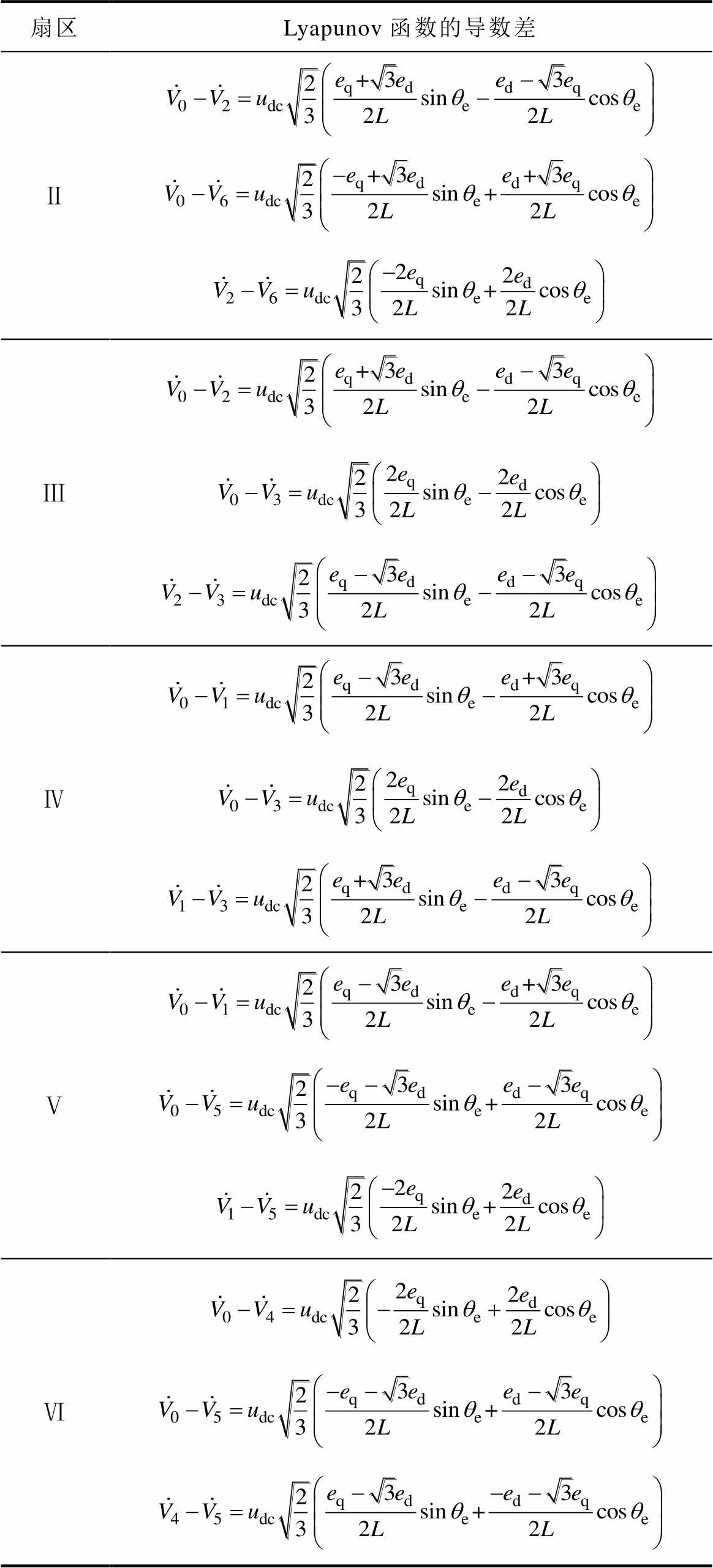
扇区Lyapunov函数的导数差 Ⅱ Ⅲ Ⅳ Ⅴ Ⅵ
根据上述分析,可绘制本文提出的基于反推控制的PMSM稳定性单矢量控制框图,如图1所示。
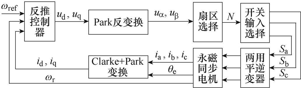
图1 基于反推控制的PMSM稳定性单矢量控制框图
Fig.1 Block diagram of PMSM stability single-vector control based on backstepping control
若以ux表示通过本文方法计算所选择的最优基本电压矢量,将传统反推控制器与本文方法的控制误差作比较,可得
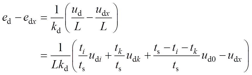 (13)
(13)
式中, 为选择最优电压矢量ux时d轴电流控制误差;
 为最优电压矢量ux的d轴分量。
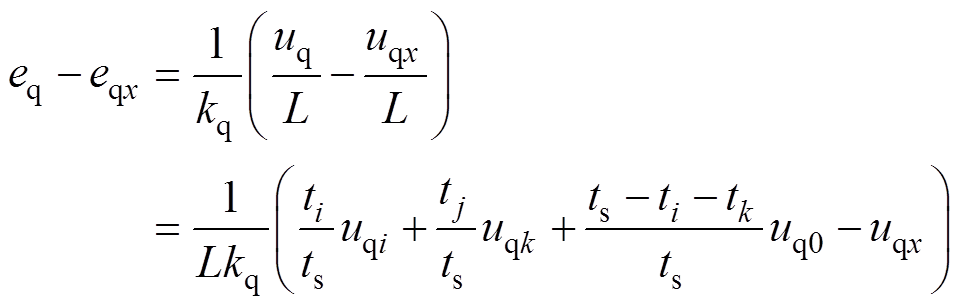 (14)
(14)
式中, 为选择最优电压矢量ux时q轴电流控制误差;
 为最优电压矢量ux的q轴分量。
传统SVPWM算法通过扇区内的三个基本电压矢量合成参考电压矢量,如图2所示,选取第一扇区的基本电压矢量u4、u6和u0为例进行分析。
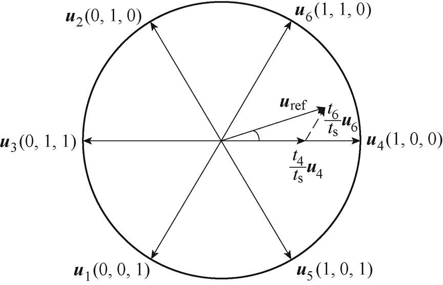
图2 第一扇区内基本电压矢量合成
Fig.2 Composite plot of the basic voltage vector in the first sector
1)取基本电压矢量u4
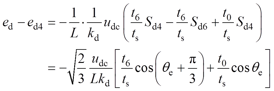 (15)
(15)
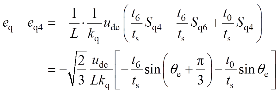 (16)
(16)
式中, 为选择最优电压矢量u4时d轴电流控制误差;
 为选择最优电压矢量u4时q轴电流控制误差;
 、
、 分别为开关函数
 的d轴与q轴分量;
 、
、 分别为开关函数
 的d轴与q轴分量。
当qe∈(0, 30°) 时,式(15)总小于零,而式(16)则总大于零,这表明,当位于第一扇区前半部分时,与反推控制相比,若基本电压矢量u4为最优基本电压矢量,本文提出的稳定性单矢量控制策略在q轴电流上的控制误差比反推控制小。
2)取基本电压矢量u6
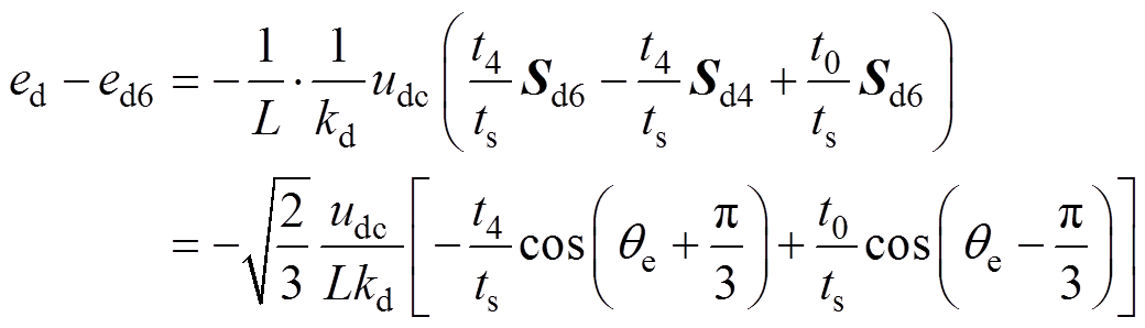 (17)
(17)
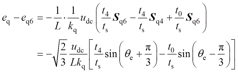 (18)
(18)
式中, 为选择最优电压矢量u6时d轴电流控制误差;
 为选择最优电压矢量u6时q轴电流控制误差。
当qe∈(0, 30°) 时,式(17)的正负无法确定,而式(18)则总小于零,故当位于第一扇区前半部分时,若最优基本电压矢量为u6,则本文控制方法下,d轴电流的控制误差与反推控制的误差大小关系难以量化比较,而q轴电流误差则变大。
3)取基本电压矢量u0
 (19)
(19)
 (20)
(20)
式中, 为选择最优电压矢量u0时d轴电流控制误差;
 为选择最优电压矢量u0时q轴电流控制误差。
当qe∈(0, 30°) 时,式(19)和式(20)的正负由 和
和 的正负决定。
总之,在保持稳定性的前提下,与反推控制相比,本文基于反推控制的稳定性单矢量控制方法的误差有些情况下变大、有些情况下变小、有些情况下保持不变,后续将进一步通过仿真予以对比分析。
为验证本文提出的稳定性单矢量控制策略的有效性,在Matlab平台中搭建了相应控制模型。
本文所用PMSM的额定参数见表3。为更好地体现本文控制策略的有效性,将本文控制策略与反推控制以及MPCC策略分别进行了对比仿真。
表3 PMSM参数
Tab.3 Parameters of PMSM
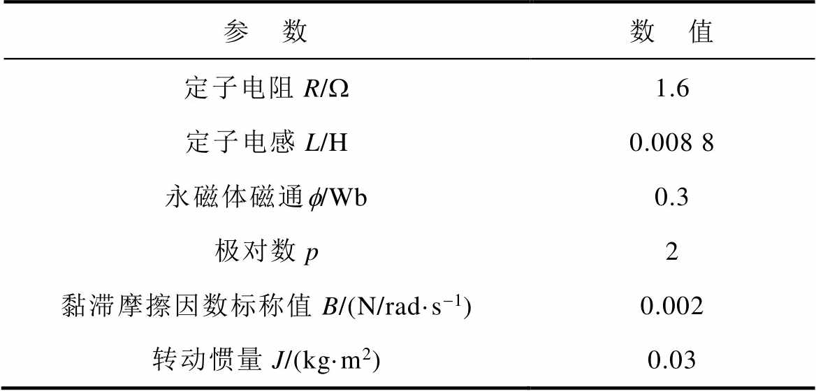
参 数数 值 定子电阻R/W1.6 定子电感L/H0.008 8 永磁体磁通f/Wb0.3 极对数p2 黏滞摩擦因数标称值B/(N/rad·s-1)0.002 转动惯量J/(kg·m2)0.03
经过反复测试,本文中的反推控制器的控制参数确定为:=150、=1 500和=1 000。
本文中的MPCC是以电流预测控制器来代替传统双闭环控制中的电流环PI控制器,外环转速环仍采用PI控制,参数P=10,I=100,仿真时间均为5 s。
1)第1组仿真:算力消耗对比
为了比较本文方法和MPCC的算力消耗,本文设置了不同的仿真时间,利用Matlab自身的计时模块统计MPCC和本文方法实际的运行时间,对比结果如图3所示。
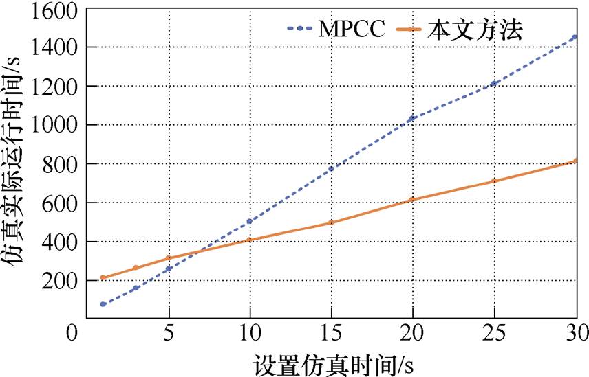
图3 本文策略与MPCC的算力消耗对比
Fig.3 The computing power consumption of the strategy in this article is compared with that of MPCC
由图3可以看出,随着仿真时间增加,两种算法的运行时间都在增大,但与MPCC相比,本文方法消耗时间更短,同时随着仿真时间增大,本文方法优势更明显。
2)第2组仿真:驱动恒转矩、恒转速负载
该仿真为PMSM额定参数条件下,驱动恒转矩负载仿真实验,参考转速 =5 rad/s,负载转矩
 = 10 N·m,本文方法控制效果和传统MPCC策略的对比如图4所示。
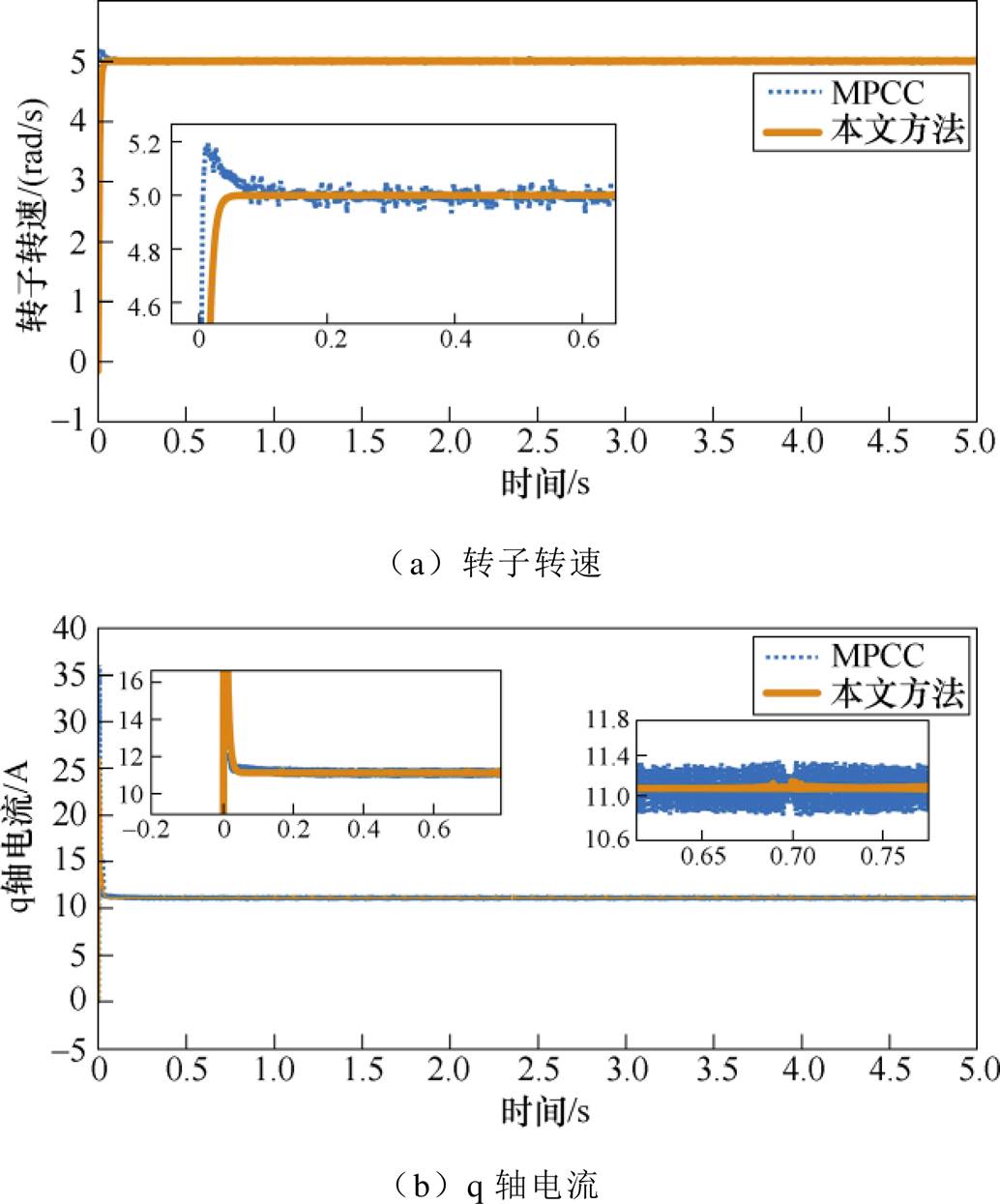
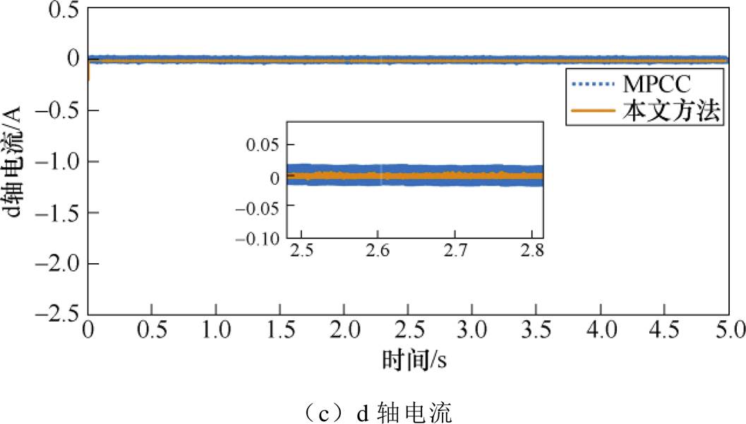
图4 恒转矩恒转速下本文策略与MPCC对比
Fig.4 Comparison of the proposed strategy with MPCC at constant torque and speed
图4a显示,在MPCC策略下,电机起动时转子转速会经历一个不小的抖动过程,本文策略则几乎不发生抖动,并且在系统稳定运行时,本文方法控制下的转子转速更平稳、波动更小。在图4b中,起动时本文策略下q轴电流抖动更小。图4c显示起动时本文方法d轴电流的抖动幅值略大,但进入稳态后本文策略下电流的波动更小。
3)第3组仿真:驱动变转矩、恒转速负载
第3组仿真为PMSM在额定参数条件下,参考转速 =5 rad/s,负载转矩
 在仿真运行到2 s时由5 N·m突变为10 N·m,将MPCC策略和本文方法进行对比,结果如图5所示。
图5 变转矩恒转速下本文策略与MPCC对比
Fig.5 Comparison of the proposed strategy with MPCC under variable torque and constant speed
由图5a可知,当转矩发生突变时,两种控制策略下的转速都会受到影响,但本文方法受影响更小,突变更小。在图5b中,两种控制策略下的q轴电流均随负载转矩增大而增大。图5c显示,本文方法下d轴电流在转矩突变时突变略大一些,但在进入稳态运行后,本文控制方法下的电机转速和电流波动均更小。
4)第4组仿真:取不同基本电压矢量时控制性能对比分析
该组仿真为PMSM在额定参数条件下,驱动恒转矩、恒转速负载仿真实验,参考转速=5 rad/s,负载转矩=10 N·m,对本文提出的稳定性单矢量控制策略的性能进行仿真分析。
具体仿真方法为:当扇区选择结果为第一扇区时,在选择最优电压矢量的程序中,人为改变最优电压矢量,比如,若最优基本电压矢量为u6时,分别选取第一扇区基本电压矢量u4和第四扇区基本电压矢量u1作为最优电压矢量进行控制,仿真对比结果如图6所示。
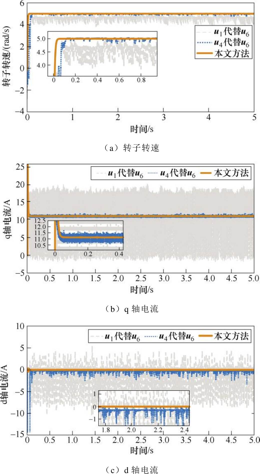
图6 不同基本电压矢量时的控制性能对比
Fig.6 Comparison of control performance with different basic voltage vectors
由图6可知,本文控制策略下各输出量控制性能均优于其他两种对比算法,并且,选择电压矢量u1代替电压矢量u6作为最优电压矢量时,相比选择电压矢量u4进行替代,控制稳定性更差,且控制误差更大。究其原因,当扇区选择为第一扇区时,参考电压矢量、电压矢量u4及电压矢量u6均在第一扇区内,而电压矢量u1不在第一扇区,且与第一扇区相差较远。可见,若不采用最优电压矢量,而是任意地选择某个电压矢量进行开关控制,转速及电流误差均会变大且控制效果明显变差,证明了本文稳定性单矢量控制策略的有效性。
5)第5组仿真:驱动恒转矩、变转速负载
为验证第4节控制策略的性能分析,本文将传统的反推控制也进行仿真分析。该仿真为PMSM额定参数条件下,驱动恒转矩负载仿真实验,参考转速在第2 s时由5 rad/s突变为7 rad/s,负载转矩=10 N·m,将反推控制、本文方法和MPCC三种控制策略进行对比,控制效果的对比如图7所示。
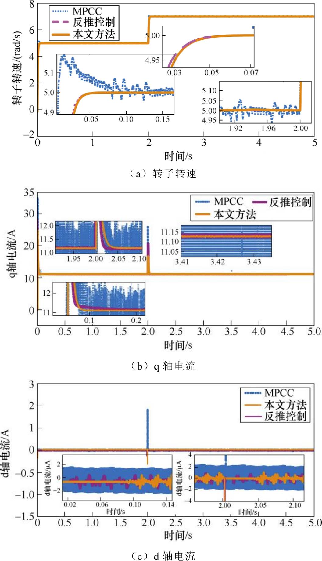
图7 恒转矩变转速下三种控制策略对比
Fig.7 Comparison of three control strategies under constant torque and variable speed
由图7a可知,MPCC下转子转速在发生电机起动和参考转速变化时仍会出现突变,并且稳态过程中波动最明显;与常规反推控制相比,本文控制策略在电机起动时转速响应略慢,但稳态运行时控制效果相差不大;图7b显示,相比于本文控制策略,当参考转速发生变化时,MPCC和传统反推控制下q轴电流的突变更大,但反推控制下q轴电流在发生扰动时响应最快;图7c表明,在参考转速发生变化时,MPCC的d轴电流突变方向与本文方法相反且突变最大,且在稳态运行过程中波动最大,本文方法和反推控制两种控制策略的控制效果差别不大,这表明本文方法能够实现对于转速和电流的准确追踪。
6)第6组仿真:控制方法鲁棒性分析
为了验证本文控制方法的鲁棒性,讨论在电阻和电感存在误差的情况下算法的控制性能,即分析当电感和电阻偏离各自额定值(见表3)时转子转速的追踪效果,R的取值范围是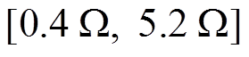 ,L的取值范围是
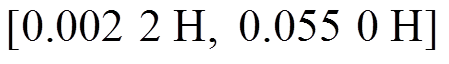 ,其中参考转速在第2 s时由5 rad/s突变为7 rad/s,负载转矩=10 N·m,具体结果如图8和图9所示。
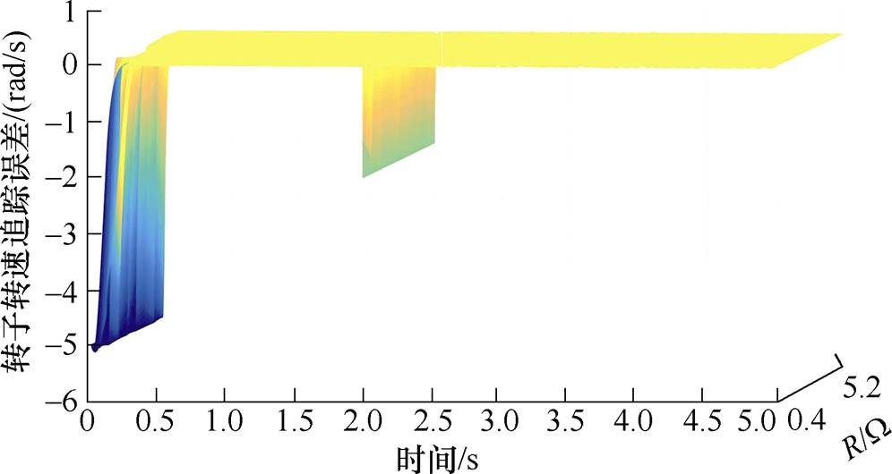
图8 R偏离额定值时转速追踪效果
Fig.8 Speed tracking when R parameters deviate from the rated value
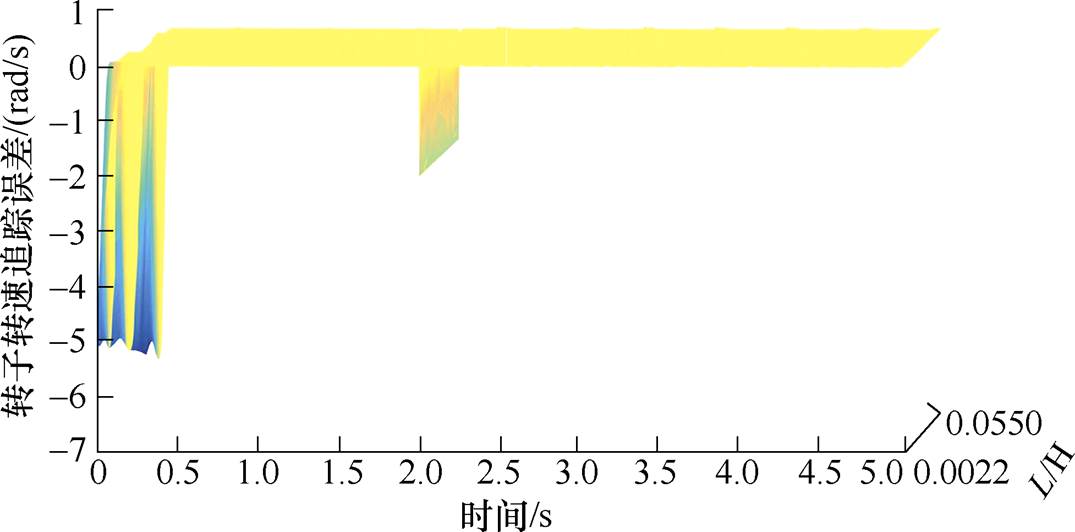
图9 L参数偏离额定值时的转速追踪
Fig.9 Speed tracking when L parameters deviate from the rated value
由图8和图9可以看到,当电阻和电感参数偏离额定值时,转子转速会产生一些小幅度的波动,但稳态运行时转子转速的追踪误差基本都能维持在0,可见本文提出的控制策略具有良好的鲁棒性。
为进一步验证本文算法优越性,设计了如图10所示的永磁同步电机驱动涡簧负载的实验平台,电机驱动由两个涡簧箱串接形成的联动式储能箱,还开发了数据采集与监控系统,采样频率为10 kHz,通过上位机操作下达各类控制指令,如图11所示,平台采用TMS320F28335作为控制芯片,系统参数与仿真部分保持一致。
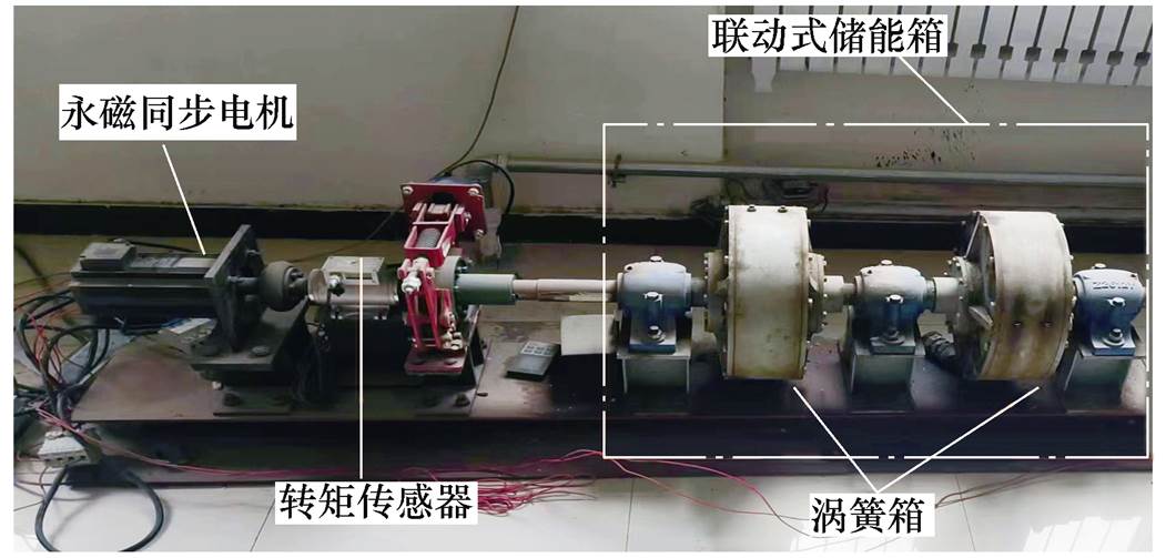
图10 PMSM驱动涡簧负载实验平台
Fig.10 Experiment setup of spiral spring load drived by PMSM

图11 控制系统、变频器和速度显示
Fig.11 Control system, inverters and speed display
1)第1组实验:驱动变转矩、变转速涡簧负载
进一步验证本文算法优越性,将其应用于PMSM驱动变转矩、变惯量涡簧负载实验,并将实验结果与MPCC策略进行对比。PMSM的参数与仿真用的参数保持一致,涡簧负载具体参数见表4。
表4 涡簧材料参数
Tab.4 Material parameters of spiral spring
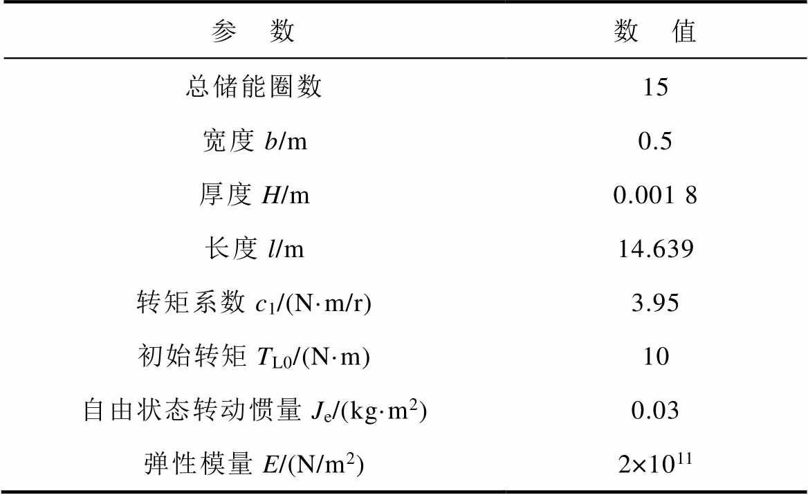
参 数数 值 总储能圈数15 宽度b/m0.5 厚度H/m0.001 8 长度l/m14.639 转矩系数c1/(N·m/r)3.95 初始转矩TL0/(N·m)10 自由状态转动惯量Je/(kg·m2)0.03 弹性模量E/(N/m2)2×1011
同时,参考转速在实验的第2 s时由5 rad/s变为7 rad/s,涡簧扭矩和惯量变化情况如式(21)所示,实验对比结果如图12所示。
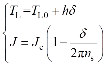 (21)
(21)
其中
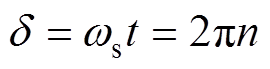 (22)
(22)
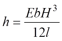 (23)
(23)
式中,h为涡簧系数; 为涡簧轴旋转额角速度;
 为时间;
为时间; 为外部扭矩作用下涡簧工作的圈数;ns为涡簧总储能圈数;Je为涡簧完全释放时的转动惯量;为涡簧扭矩;b为涡簧宽度;H为涡簧厚度;l为涡簧长度;E为弹性模量;TL0为初始转矩。
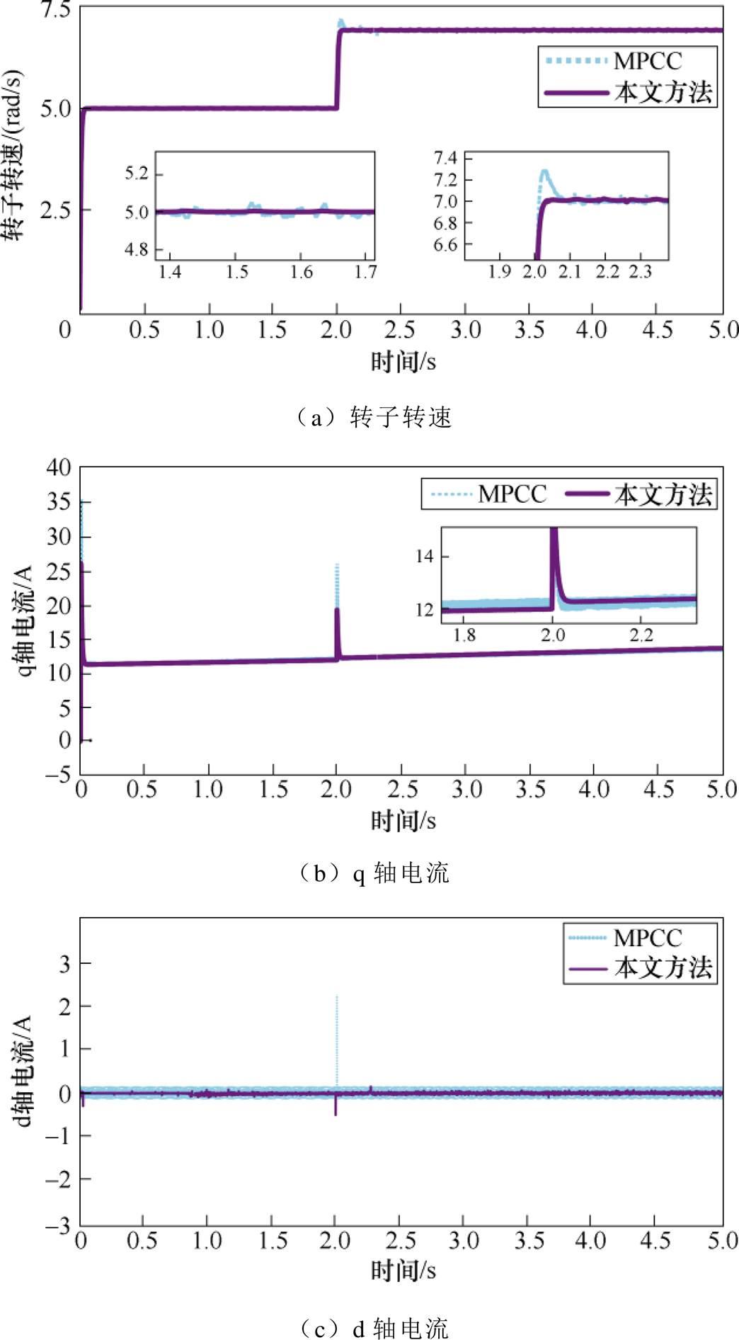
图12 驱动变转矩、变转速涡簧负载实验对比结果
Fig.12 Comparison results of drive variable torque and variable speed spiral spring load experiments
由图12a可知,在参考转速发生变化时,MPCC下的转子转速会发生一个较大突变,而本文方法在参考转速变化时几乎不发生突变,且控制效果更稳定。由图12b可再一次验证由图5b得出的结论,即q轴电流与负载转矩成比例变化,且当参考转速由5 rad/s变为7 rad/s时,q轴电流斜率变大,其变化速率与转子转速也表现出类似的变化关系。图12c显示,两种方法下的d轴电流在转速变化时突变方向相反,且本文方法下d轴电流突变以及抖动均更小。因此,由实验验证,当参考转速发生变化时,本文方法下PMSM驱动变转矩变惯量涡簧负载时电流突变和波动均更小。
2)第2组实验:恒转速突变转矩驱动涡簧负载
参考转速在实验过程中始终维持5 rad/s,在实验运行到第2 s时,切掉一个涡簧箱,模拟转矩突然变化情形,转矩和转动惯量的变化如图13所示,本文方法和MPCC下的转速和电流对比如图14所示。
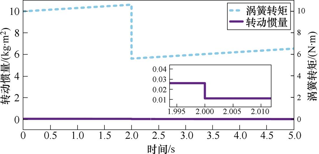
图13 涡簧负载的转矩和转动惯量变化曲线
Fig.13 Torque and moment of inertia change curves of spiral spring load
由图14a可知,在第2 s切掉一个涡簧箱之后,MPCC和本文方法下的转子转速均会发生突变,但本文方法下转速的突变更小,且稳定运行时MPCC下转速波动明显更大;由图14b可知,两种控制策略下,q轴电流均随着转矩增大而增大,在转矩突然降低时,q轴电流也下降,在整个实验过程中,本文控制方法下q轴电流波动更小;进一步由图14c可以看到,当转矩突然下降时,与MPCC相比,本文控制方法下d轴电流突变更为明显,但进入稳态后,d轴电流抖动更小。
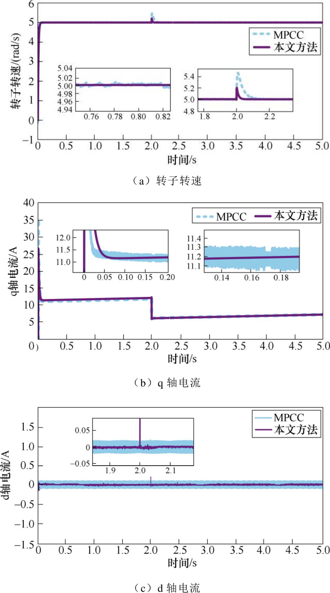
图14 电机驱动涡簧负载实验结果对比
Fig.14 Comparison chart of experimental results of motor driving spiral spring load
1)将各扇区三个基本电压矢量的Lyapunov导数进行比较,结合电流误差变量和转子位置角度,可较方便、快捷地选出让Lyapunov导数最小的基本电压矢量,该电压矢量即为稳定的最佳基本电压矢量。
2)相比传统MPCC策略,本文控制策略在设置仿真时长时的算力消耗更有优势,而且本文控制策略下转速和电流在稳态运行、外部扰动以及驱动变转矩变惯量涡簧负载时的波动均更小,具有更好的稳定性。
3)与反推控制相比,本文方法的控制效果相差不大,甚至部分情况下控制效果比反推控制更好,抖动更小。
附 录
1. dq0坐标系下开关矢量表达式推导
由于
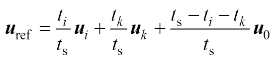 (A1)
(A1)
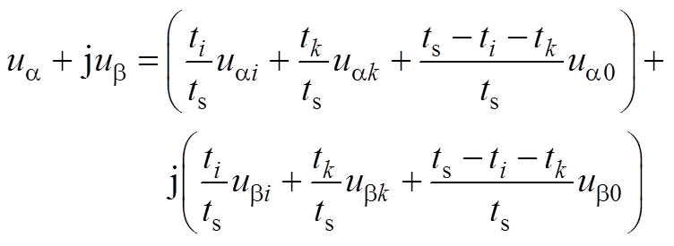 (A2)
(A2)
式中,uref为参考电压矢量;ua、ub 分别为定子电压的a、b 轴分量;uai、ubi分别为基本电压矢量ui的a、b 轴分量;uak、ubk分别为基本电压矢量uk的a、b 轴分量;ua0、ub0分别为基本电压矢量u0的a、b 轴分量。
根据式(A2),令等式两边的实部和虚部分别相等,由此得到ua、ub 表达式分别为
 (A3)
(A3)
 (A4)
(A4)
接下来,根据Park变换,可得定子电压的d、q轴分量分别为
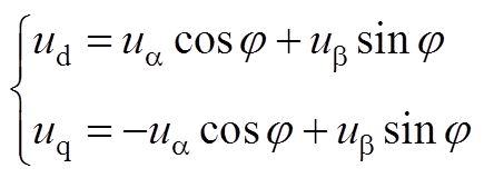 (A5)
(A5)
式中,j为a 轴与A轴的夹角。将式(A3)、式(A4)代入式(A5),可得
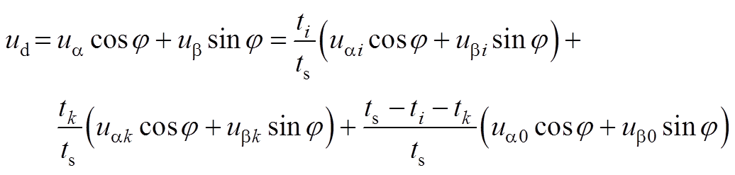
 (A6)
(A6)
 (A7)
(A7)
即有
 (A8)
(A8)
 (A9)
(A9)
证毕!
2.稳定电压矢量存在性证明
将式(8)代入式(6),并结合式(1),可得
 (A10)
(A10)
其中
 (A11)
(A11)
 (A12)
(A12)
 (A13)
(A13)
参考文献
[1] Li Longfei, Xiao Jie, Zhao Yun, et al. Robust position anti-interference control for PMSM servo system with uncertain disturbance[J]. CES Transactions on Elec- trical Machines and Systems, 2020, 4(2): 151-160.
[2] Chen Qiping, Xu Zhihui, Hu Yiming, et al. Research on torque ripple optimization of permanent magnet synchronous motor for electric vehicle based on modular poles[J]. IEEJ Transactions on Electrical and Electronic Engineering, 2023, 18(4): 613-622.
[3] 周荔丹, 李杏, 姚钢, 等. MP-MMC驱动六相永磁风力发电机建模及控制研究[J]. 电机与控制学报, 2019, 23(5): 84-92.
Zhou Lidan, Li Xing, Yao Gang, et al. Modeling and control for six phase permanent magnet wind turbine driven by MP-MMC[J]. Electric Machines and Control, 2019, 23(5): 84-92.
[4] 余洋, 田夏, 从乐瑶, 等. 基于反推控制和模态估计的永磁同步电机驱动柔性涡簧储能控制方法[J]. 电工技术学报, 2019, 34(24): 5084-5094.
Yu Yang, Tian Xia, Cong Leyao, et al. Energy storage control method of flexible spiral springs driven by permanent magnet synchronous motor based on backstepping control and modal estimation[J]. Transactions of China Electrotechnical Society, 2019, 34(24): 5084-5094.
[5] Xu Jinquan, Zhang Boyi, Fang Hao, et al. Guaranteeing the fault transient performance of aerospace multiphase permanent magnet motor system: an adaptive robust speed control approach[J]. CES Transactions on Electrical Machines and Systems, 2020, 4(2): 114-122.
[6] 吕从鑫, 汪波, 陈静波, 等. 永磁同步电机控制策略综述与展望[J]. 电气传动自动化, 2022, 44(4): 1-10.
Lü Congxin, Wang Bo, Chen Jingbo, et al. Review and prospect of control strategies for permanent magnet synchronous motors[J]. Electric Drive Auto- mation, 2022, 44(4): 1-10.
[7] 周长攀, 刘海峰, 景国秀, 等. 双三相永磁同步电机缺相容错运行虚拟矢量间接修正方法及其在直接转矩控制中应用[J]. 电工技术学报, 2023, 38(2): 451-464.
Zhou Changpan, Liu Haifeng, Jing Guoxiu, et al. The indirect correction method of virtual vectors for dual three-phase permanent magnet synchronous motors under the open-phase fault and its application in the direct torque control[J]. Transactions of China Electrotechnical Society, 2023, 38(2): 451-464.
[8] 于艳君, 崔明恺, 柴凤. 双绕组永磁同步电机滑模变结构控制[J]. 电工技术学报, 2022, 37(22): 5799- 5807.
Yu Yanjun, Cui Mingkai, Chai Feng.Sliding mode variable structure control of a dual-winding per- manent magnet synchronous motor[J]. Transactions of China Electrotechnical Society, 2022, 37(22): 5799- 5807.
[9] Sasaki S. Frequency-weighted angle compensator for position sensorless permanent magnet synchronous motor control[J]. IEEJ Transactions on Electrical and Electronic Engineering, 2023, 18(1): 81-90.
[10] 李争, 安金峰, 肖宇, 等. 基于自适应观测器的永磁同步直线电机模型预测控制系统设计[J]. 电工技术学报, 2021, 36(6): 1190-1200.
Li Zheng, An Jinfeng, Xiao Yu, et al. Design of model predictive control system for permanent magnet synchronous linear motor based on adaptive observer[J]. Transactions of China Electrotechnical Society, 2021, 36(6): 1190-1200.
[11] 张珍睿, 刘彦呈, 陈九霖, 等. 永磁同步电机幅值控制集模型预测控制策略[J]. 电工技术学报, 2022, 37(23): 6126-6134.
Zhang Zhenrui, Liu Yancheng, Chen Jiulin, et al. Amplitude control set model predictive control strategy for permanent magnet synchronous motor[J]. Transactions of China Electrotechnical Society, 2022, 37(23): 6126-6134.
[12] Farah N, Lei Gang, Zhu Jianguo, et al. Two-vector dimensionless model predictive control of PMSM drives based on fuzzy decision making[J]. CES Transactions on Electrical Machines and Systems, 2022, 6(4): 393-403.
[13] 苏晓杨, 兰志勇, 蔡兵兵. 永磁同步电机模型预测电流控制比较研究[J]. 电机与控制应用, 2021, 48(10): 7-13.
Su Xiaoyang, Lan Zhiyong, Cai Bingbing. A comparative research of model predictive current control for permanent magnet synchronous motor[J]. Electric Machines & Control Application, 2021, 48(10): 7-13.
[14] 李祥林, 薛志伟, 阎学雨, 等. 基于电压矢量快速筛选的永磁同步电机三矢量模型预测转矩控制[J]. 电工技术学报, 2022, 37(7): 1666-1678.
Li Xianglin, Xue Zhiwei, Yan Xueyu, et al. Voltage vector rapid screening-based three-vector model predictive torque control for permanent magnet synchronous motor[J]. Transactions of China Elec- trotechnical Society, 2022, 37(7): 1666-1678.
[15] 王从刚, 何凤有, 曹晓冬. 三相电压型PWM整流器有限开关序列模型预测电流控制[J]. 电工技术学报, 2013, 28(12): 182-190.
Wang Conggang, He Fengyou, Cao Xiaodong. Finite switching sequence model predictive current control of a three-phase voltage source PWM rectifier[J]. Transactions of China Electrotechnical Society, 2013, 28(12): 182-190.
[16] Sawma J, Khatounian F, Monmasson E, et al. Analysis of the impact of online identification on model predictive current control applied to permanent magnet synchronous motors[J]. IET Electric Power Applications, 2017, 11(5): 864-873.
[17] Wu Tao, Shi Shangyao, Zhang Dong, et al. On backstepping control for a class of multiple uncertain systems with reduced-order ESO[J]. International Journal of Control, 2023, 96(2): 309-320.
[18] 余洋, 冯路婧, 米增强, 等. 基于增量反推控制的机械弹性储能用永磁同步电机控制方法[J]. 电机与控制学报, 2021, 25(12): 1-10.
Yu Yang, Feng Lujing, Mi Zengqiang, et al. Control method of permanent magnet synchronous motors for mechanical elastic energy storage based on incre- mental backstepping control[J]. Electric Machines and Control, 2021, 25(12): 1-10.
[19] 付东学, 赵希梅. 永磁直线同步电机自适应反推全局快速终端滑模控制[J]. 电工技术学报, 2020, 35(8): 1634-1641.
Fu Dongxue, Zhao Ximei. Adaptive backstepping global fast terminal sliding mode control for permanent magnet linear synchronous motor[J]. Transactions of China Electrotechnical Society, 2020, 35(8): 1634-1641.
[20] Jin Hongyan, Zhao Ximei, Wang Tianhe. Adaptive backstepping complementary sliding mode control with parameter estimation and dead-zone modi- fication for PMLSM servo system[J]. IET Power Electronics, 2021, 14(4): 785-796.
[21] Prior G, Krstic M. Quantized-input control Lyapunov approach for permanent magnet synchronous motor drives[J]. IEEE Transactions on Control Systems Technology, 2013, 21(5): 1784-1794.
[22] Prior G, Krstic M. A control Lyapunov approach to finite control set model predictive control for permanent magnet synchronous motors[J]. Journal of Dynamic Systems, Measurement, and Control, 2015, 137(1): 011001.
[23] 齐昕, 徐德明, 苏涛, 等. 改进圆形边界限定的永磁同步电机预测控制[J]. 中国电机工程学报, 2023, 43(5): 2001-2011.
Qi Xin, Xu Deming, Su Tao, et al. Predictive control of PMSM based on improved circular boundary limitation[J]. Proceedings of the CSEE, 2023, 43(5): 2001-2011.
[24] 张古月, 吉培荣, 闫苏红, 等. 基于改进开关矢量表的三相电压型PWM整流器[J]. 电气传动, 2017, 47(4): 45-50.
Zhang Guyue, Ji Peirong, Yan Suhong, et al. Three-phase voltage source PWM rectifier based on improved switching-vector-table[J]. Electric Drive, 2017, 47(4): 45-50.
Abstract The traditional single-vector control of permanent magnet synchronous motors traverses all basic vectors and ignores the control stability. This paper proposes a stable single-vector control strategy based on backstepping control. Firstly, the mathematical model of permanent magnet synchronous motors under the dq0 coordinate system is established, and the conventional backstepping controller is derived. The switch vector expression under the dq0 coordinate system is obtained. A basic voltage vector in each control cycle is required for the six sectors to keep the control system stable. Then, according to the control voltage obtained by the conventional backstepping controller, the sector of the optimal voltage vector is determined. The selection method of the optimal basic voltage vector is proposed. That is, the derivatives corresponding to the Lyapunov function in the three basic voltage vectors are compared in pairs, the basic voltage vector corresponding to the minimum derivative value of the Lyapunov function is selected as the optimal basic voltage vector, and the basic voltage vector derivative difference strategy table of the six sectors is given. Thus, the switching state is determined. Finally, the control performance of different basic voltage vectors, including the optimal basic voltage vector, is compared.
Simulation verification is carried out. The results show that the proposed control strategy is cost-effective. When driving constant or variable torque load, the proposed control strategy effectively tracks the reference speed, which has strong stability and small output fluctuations. Suppose the optimal voltage vector is not used, but a voltage vector is arbitrarily selected for switching control. In this case, the speed and current errors become more extensive, and the control effect is significantly worse, further proving the effectiveness of the proposed control strategy. In addition, when the motor resistance and inductance parameters deviate from the rated value, the control strategy can maintain a small speed tracking error and has good robustness.
An experimental platform is constructed for permanent magnet synchronous motors to drive spiral spring load. The results show that the proposed control strategy still effectively tracks the reference speed when driving variable torque and variable inertia spiral spring loads. Compared with the traditional model of predictive current control, it has more robust stability and minor output fluctuations.
keywords:Permanent magnet synchronous motor (PMSM), backstepping control, single-vector control, basic voltage vector, power distribution
DOI: 10.19595/j.cnki.1000-6753.tces.230802
中图分类号:TM73
国家自然科学基金(52077078)和河北省自然科学基金(E2019502163)资助项目。
收稿日期 2023-05-31
改稿日期 2023-06-27
余 洋 男,1982年生,博士,教授,博士生导师,主要研究方向为电力储能技术、柔性负荷建模与调度。E-mail: ncepu_yy@163.com(通信作者)
张千慧 女,2000年生,硕士研究生,主要研究方向为电力储能技术。E-mail: 1249384229@qq.com
(编辑 崔文静)