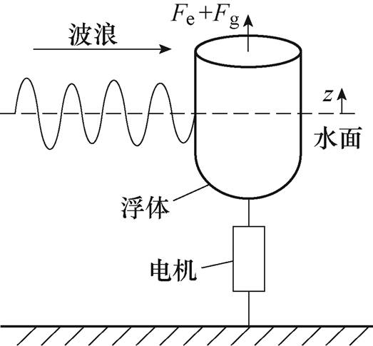
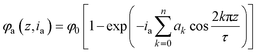
图1 波浪发电系统示意图
Fig.1 Diagram of wave energy conversion system
摘要 直线开关磁阻发电机(LSRG)由于其成本低、可靠性高,十分适合直驱式波浪发电的应用场合。为了提升波浪能的捕获效率,波浪发电装置需要采取优化控制策略来主动地改变浮体-波浪间的相互作用,此类策略要求电机在全部四个象限下具备推力指令跟踪的功能。然而,现有的波浪发电LSRG往往工作在固定开通-关断角的模式下,无法满足这一要求。为此,该文提出一种基于优化推力分配函数的LSRG控制方案,以使电机在四象限下以最小的推力波动实现推力指令跟踪。提出考虑直流电压受限这一约束条件的优化推力分配函数,并进一步讨论其在四象限下的实现方案。搭建LSRG-永磁同步电机对拖实验平台以模拟实际波浪发电工况,在恒定速度、阻尼控制和谐振控制的运行条件下,验证了所提出控制方案的有效性。
关键词:波浪发电 直线开关磁阻发电机 推力波动抑制
波浪能相比于风能与光伏能源,具有功率密度高、可预测性好和土地占用小等优点,是极具发展潜力的可再生能源[1]。波浪发电装置按照能量转换形式大致可分为气压传动、液压传动、机械传动和直驱四类。其中,直驱式装置采用浮体运动直接带动直线电机动子的方案,取消了中间能量转换环节,相比于前三者具有更高的能量转换效率[2]。目前大多数直驱波浪发电装置采用直线永磁同步发电机(Linear Permanent Magnet Synchronous Generator, LPMSG),其具有推力密度大、控制简单等优点。然而,LPMSG的制造成本较高,同时含有永磁体,在复杂且维护困难的波浪发电工况下,长期运行的可靠性较低[3]。直线开关磁阻发电机(Linear Switched Reluctance Generator, LSRG)的动子由铁磁材料制成,相比于永磁体降低了成本并提升了可靠性,近年来已经成为LPMSG较为理想的替代方案[4]。
目前,针对应用于波浪发电的LSRG本体,学者已经提出了各类设计方案,包括双面式[5]、圆筒式[6]和基于互感的结构[7]等。然而,波浪发电工况对LSRG的控制同样提出了新的要求。作为波浪发电学界的共识,通过电机对装置施加特定的优化控制能够大幅度提升装置的能量捕获效率[8]。该优化控制的目标往往是驱使系统达到某种谐振条件以取得最大化能量输出,如双自由度控制[9]、模型预测控制[10]和神经网络控制[11]等。在此类控制下,电机运行具有两个关键特点:①电机的控制目标是跟踪某个推力指令;②电机的运行范围覆盖所有四个象限——即电机需实现等效四象限推力源的功能。对于LPMSG而言,成熟的矢量控制技术可以方便地实现此功能[12];而LSRG由于其非线性磁路特性,实现推力控制较为复杂,且控制效果可能存在较大的推力波动。在现有研究中,一方面,LSRG在波浪发电中的应用往往基于简单的开通-关断角控制,这时电机总是产生阻尼推力[3, 5],远未达到波浪发电所要求的优化控制条件,能量捕获效率存在较大提升空间;另一方面,虽然对于LSRG的推力(转矩)波动抑制已有较多研究,如基于改进转矩分配函数的控制[13]、直接瞬时转矩控制[14]和分段式谐波注 入[15]等,但此类方法仍亟待引入波浪发电工况中并进行测试验证。为此,文献[16]提出了一种LSRG电流波形设计方法并实现了四象限运行。然而,该研究只考虑了不含磁路饱和的简化电机模型,而实际LSRG的运行范围往往包含饱和区;此外,该方法也只在仿真环境中得到验证,无法考虑实际装置的扰动、噪声等问题。
本研究针对波浪发电的上层优化控制对下层电机控制的基本需求,提出一种基于推力分配函数的LSRG控制方案,并对其进行实验验证。首先建立LSRG的数学模型并介绍其基本控制方式;其次提出推力分配函数设计的目标函数和约束条件并建立对应优化问题;然后基于实测得到的电机磁路参数值,求解最优推力分配函数;最后在搭建的LSRG-永磁同步电机(Permanent Magnet Synchronous Motor, PMSM)对拖平台上模拟了真实波浪发电工况并对所提出方法进行验证。实验结果显示,所提出的控制方案能够在四个象限下实现推力指令跟踪和推力波动抑制,以满足波浪发电优化控制的要求。
典型单浮体点吸式直驱波浪发电系统示意图如图1所示。图中,浮体与电机动子相连接,前者在波浪激励下做往复运动,从而带动后者进行发电。浮体受到外界波浪的激励力、电机推力以及水动力学-机械系统自身的辐射和阻尼作用。
图1 波浪发电系统示意图
Fig.1 Diagram of wave energy conversion system
系统频域数学模型为
 (1)
(1)
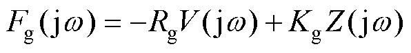
式中, 为虚数单位;
 为频率;
为频率; 、
、 和
和 分别为浮体速度、波浪激励力和电机推力;
 、
、 、
、 、
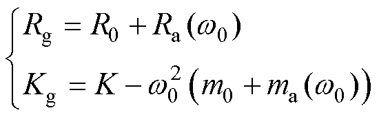
、 和
和 分别为浮体质量、附加质量、机械阻尼、辐射阻尼和静浮力系数(其中和是频率的函数)。
为了提升波浪能捕获效率,需要通过电机施加合适的控制来改变浮体与波浪的相互作用。典型的控制方法包括线性双/单自由度控制。双自由度控制(即谐振控制)有
 (2)
(2)
式中,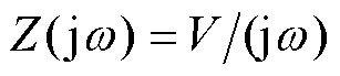 为浮体位置;
 和
和 分别为电机等效阻尼和弹性系数。考虑规则波的情况,即波浪只存在单一频率分量
 ,则最大功率提取应满足谐振条件为
 (3)
(3)
而单自由度控制(即阻尼控制)仅包含阻尼 项,有
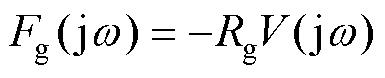 (4)
(4)
由阻抗匹配条件,其最优系数为
 (5)
(5)
在实际应用中,式(2)和式(4)中系数需要根据实际波浪条件和系统约束等因素进行调节。
对于LSRG而言,在单自由度控制下动子做往复直线运动,电机推力的方向总是与速度方向相反,即工作在一、三象限;而在双自由度控制下,电机推力除阻尼项外还包含关于动子位置的弹性项,这时其工作在全部四个象限。因此,波浪发电优化控制对LSRG的要求是在全部四个象限下均可实现推力指令跟踪。
本文研究三相6/4极LSRG,其驱动电路为不对称半桥拓扑,如图2所示。图中每相上下开关共有00、01、10、11四种导通状态,在电流连续时对应相绕组端电压分别为 、0、0、
、0、0、 。通过合适的脉冲宽度调制方法可以得到所需的相电压。
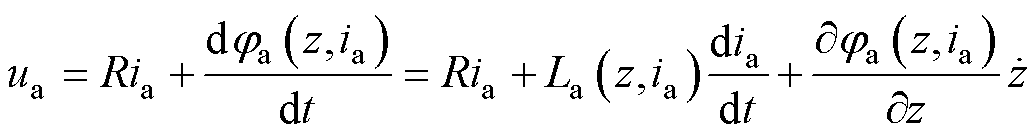
记LSRG动子位置为 ,以A相为例,绕组电压方程为
 (6)
(6)
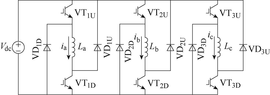
图2 基于不对称半桥拓扑的LSRG驱动电路
Fig.2 LSRG drive circuit based on the asymmetrical half bridge topology
式中, 和
和 分别为A相绕组端电压和电流;
 为电阻;
为电阻; 为磁链;
为磁链; 为电感。所产生的推力
 计算为
计算为
 (7)
(7)
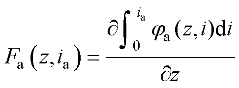
注意到,LSRG的磁链、电感和推力均为转子位置和电流的函数,且后两者均能从磁链导出。本文采用文献[17]中模型,使用指数函数和傅里叶级数对进行建模。记LSRG极距为 ,磁链模型为
 (8)
(8)
式中, 和
和 为模型参数;
 为正弦分量个数。B相和C相参数分别滞后A相
 和
和 位置。典型LSRG推力特性如图3所示。
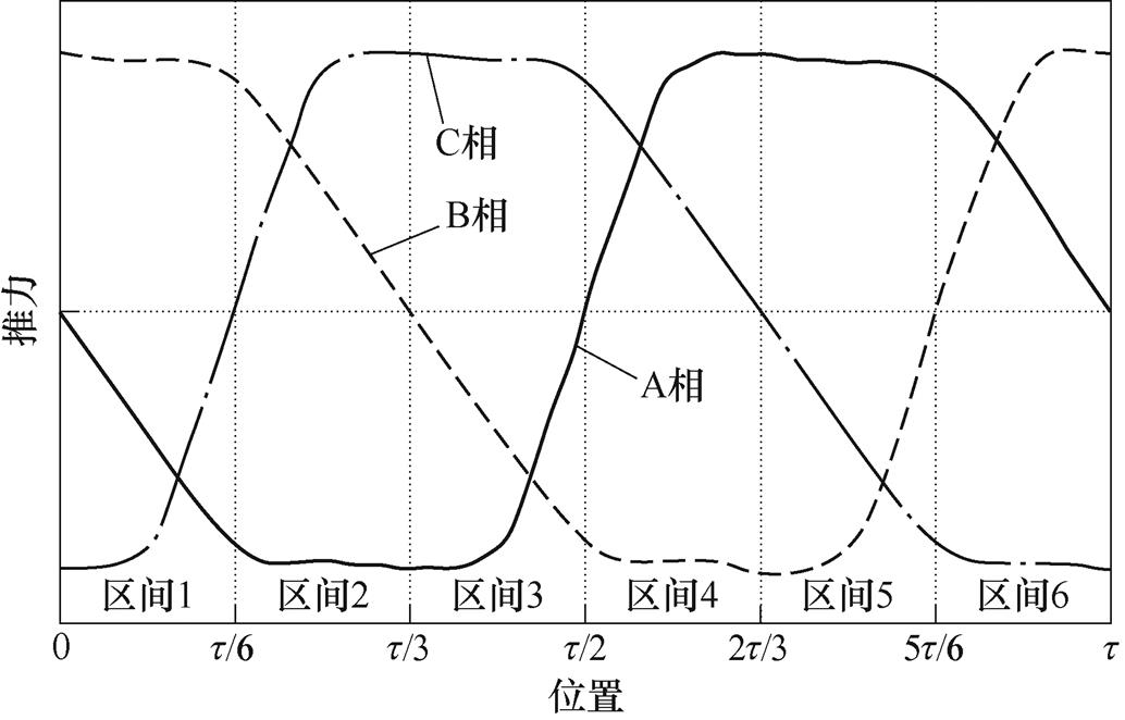
图3 6/4极LSRG推力特性示意图
Fig.3 Force characteristics of a 6/4 pole LSRG
LSRG的基本控制方式之一是令任何时刻有且只有一相导通且通以某恒定电流 ,即
,即
 (9)
(9)
式中, 为A相电流参考值;
 和
和 分别为恒电流控制的开通位置和关断位置,且
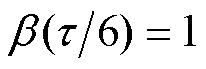
 。开通位置应选为电流产生推力能力较大的位置区间。该控制方法虽然简单,但由于LSRG复杂的推力(即)特性,令相电流为恒定值所产生的推力波动很大。
推力分配函数是实现推力控制的有效方法。与恒定电流指令不同,其直接给出各相的推力参考值,再通过Fa反求得所需的电流参考值。观察图3可见,电机极距可以分为1~6六个区间,每个区间长度为 。给定推力参考值Ft,在5、1、3区间内该推力应分别由A、B、C相单独提供,而在6、2、4区间内应分别由AB、BC、CA两相共同提供。在后一种情况下,总推力应根据电流产生推力的能力合理地分配给对应两相。定义推力分配函数为
 ,且
,且 ,
, ,以AB两相在
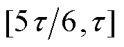 区间的切换过程为例,推力指令
 、
、 分别为
分别为
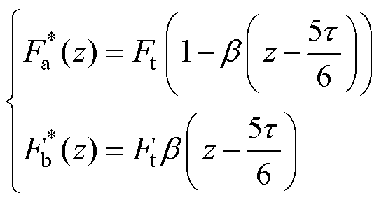 (10)
(10)
一般正弦型推力分配函数较为常见,其表达式为
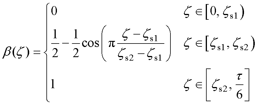 (11)
(11)
式中, 分别为正弦推力分配函数的开通和关断位置。
由于LSRG所具有的复杂推力特性,实现上述推力指令所需要的参考电流为不规则波形。正弦形式的推力分配函数仅能控制开通位置和关断位置,自由度有限,无法保证所得到的参考电流在有限的直流母线电压下能够被实时跟踪。为此,需要考虑完全自由度的推力分配函数设计。
此设计的目标是在波浪发电运行所可能出现的最大速度 和最大推力
和最大推力 下,产生对应的电流指令波形所需的驱动电压小于直流母线电压
 。只要在这一最坏情况下直流电压能够满足电流跟踪要求,则在全部运行区间内都能够满足。设计过程如下:首先,关断相和开通相的推力指令和由式(10)给出,通过模型可以反求得电流指令和
 ,其应满足
,其应满足
 (12)
(12)
通常将电流损耗作为目标函数,其正比于
 (13)
(13)
记 、
、 为速度下的磁链变化率,忽略电阻压降,有
 (14)
(14)
则驱动电压约束表示为
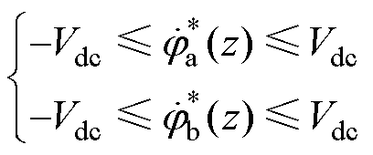 (15)
(15)
于是可以得到优化问题如下
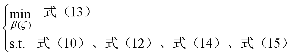 (16)
(16)
最终只需对上述方程进行离散化处理,使用数值微分,可将式(16)问题转化为非线性规划问题,进而求解非线性规划问题即可。最终得到一个离散推力分配向量(数组),存储在控制器中,在线运行中取插值即可。
将上述分析推广到ABC三相和四象限运行的情况。在确定 后,当
后,当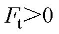 时,不同位置处各相推力分配系数见表1;相应地,
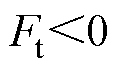 时,推力分配系数见表2。注意到,由于忽略了电阻压降,上述推力分配系数只取决于推力参考值的方向,与速度方向无关。同时,由于每相的推力特性是中心对称的,推力方向改变后,推力分配函数也应作相应的变换。
最终得到的控制系统框图如图4所示。首先,上级波浪发电优化控制器(即单自由度/双自由度控制)下发总推力指令;然后,所提出的四象限推力分配策略将其分配给各相;最后,通过反查表得到各相对应电流指令,由电流控制器实现电流跟踪。
表1 不同位置处三相推力分配系数(推力指令为正时)
Tab.1 Calculation of force sharing coefficients for three phases at different positions (positive force command)
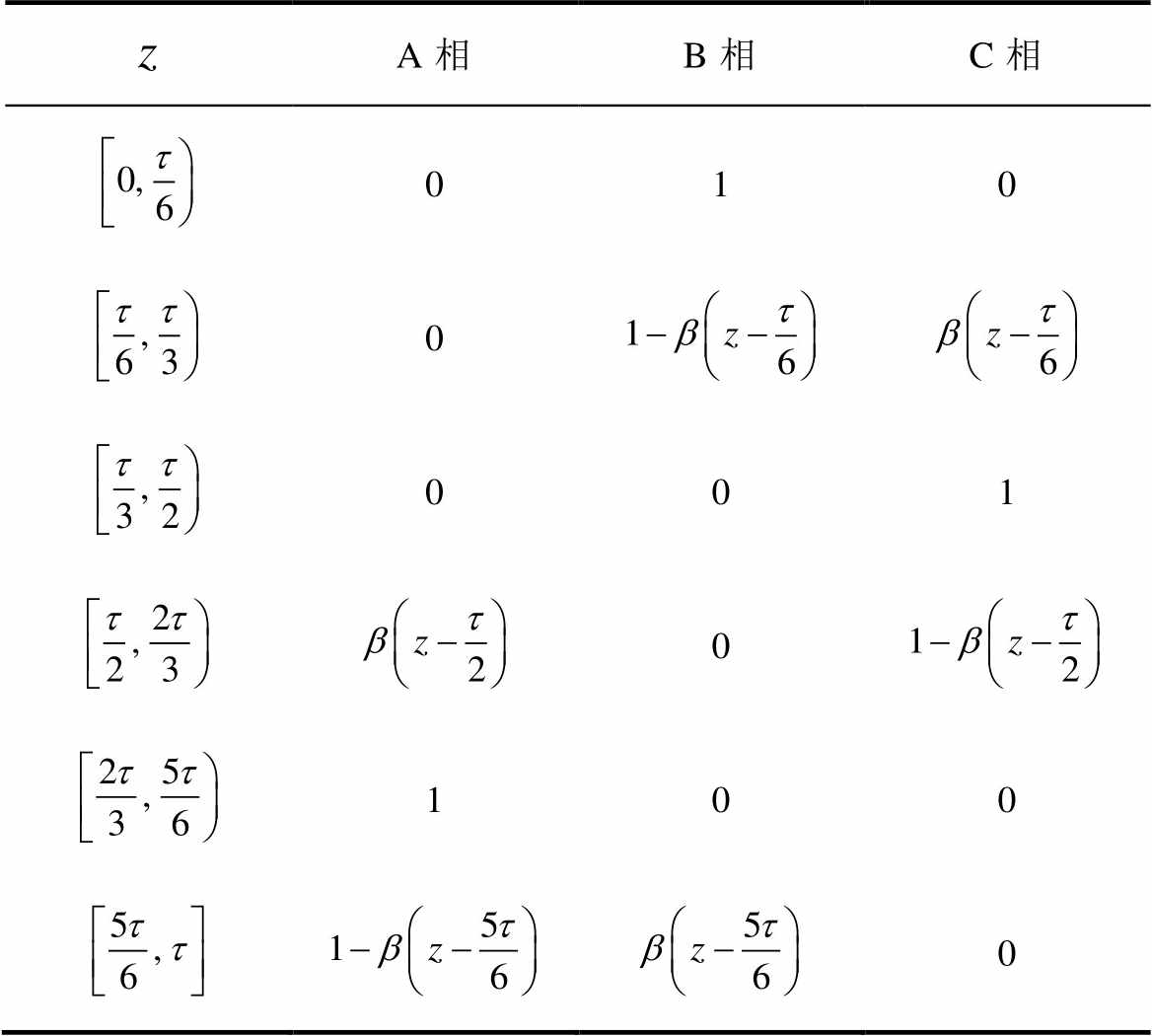
A相B相C相 010 0 001 0 100 0
表2 不同位置处三相推力分配系数(推力指令为负时)
Tab.2 Calculation of force sharing coefficients for three phases at different positions (negative force command)
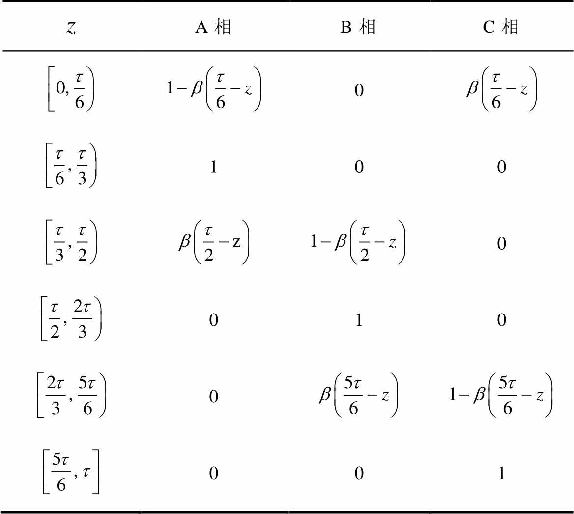
A相B相C相 0 100 0 010 0 001
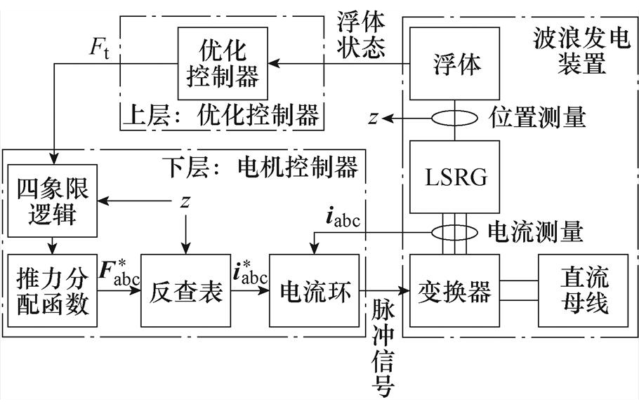
图4 四象限推力控制系统框图
Fig.4 Diagram of the four-quadrant force controller
下面搭建LSRG-PMSM对拖平台并对所提出的控制进行实验验证。所制造的LSRG为6/4极,采用基于文献[18]的磁路结构,并进一步使用基于熵值法的多目标灵敏度分层优化方法进行参数设计,以兼顾电机效率、推力密度等指标[18]。电机每相有两个绕组并联,极距0.044 7 m,直线导轨长0.8 m。LSRG驱动采用基于IGBT的不对称半桥回路,开关频率为10 kHz,直流母线电压为200 V,后端连接双向直流电源。使用双向电源的原因在于,电机工作在全部四个象限下,包括发电和电动模式,此时系统整体功率并非单向,而是存在无功功率交换。LSRG的动子经过滚珠丝杠与一台旋转PMSM的转子连接,后者工作在速度环或位置环模式下,用于模拟波浪发电工况(相当于原动机)。实验平台如图5所示。
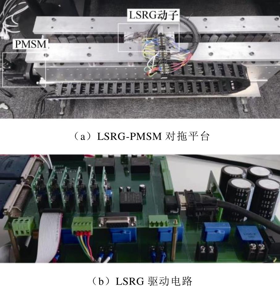
图5 LSRG-PMSM对拖平台示意图
Fig.5 Photos of the LSRG-PMSM drive platform
首先进行参数辨识。使用PMSM位置环控制LSRG动子固定于不同位置,随后给相绕组施加恒定电压激励并测量电流响应,从而计算出磁链-位置-电流的离散数值。对所得数据使用式(8)中模型进行拟合以消除噪声影响,得到 关系,进一步计算电感和推力参数。测试得到,其定子电阻约为1.5 W,磁链和推力参数如图6所示。
对比传统的正弦推力分配函数和所提出的优化推力分配函数。假定推力指令为200 N,电机速度最大值为1 m/s。正弦型推力分配函数由式(11)描述,开通和关断位置分别取 = 0和
= 0和 。优化推力分配函数是式(16)所描述的优化问题的解。在确定了推力分配函数后,开通相和关断相对应的推力指令由式(10)得到,电流指令由式(12)得到,产生这一电流所需的电压指令由式(14)得到。最终结果如图7所示。
图6 辨识得到的LSRG磁链和电感参数
Fig.6 Flux and force characteristics of LSRG obtained by parameter identification
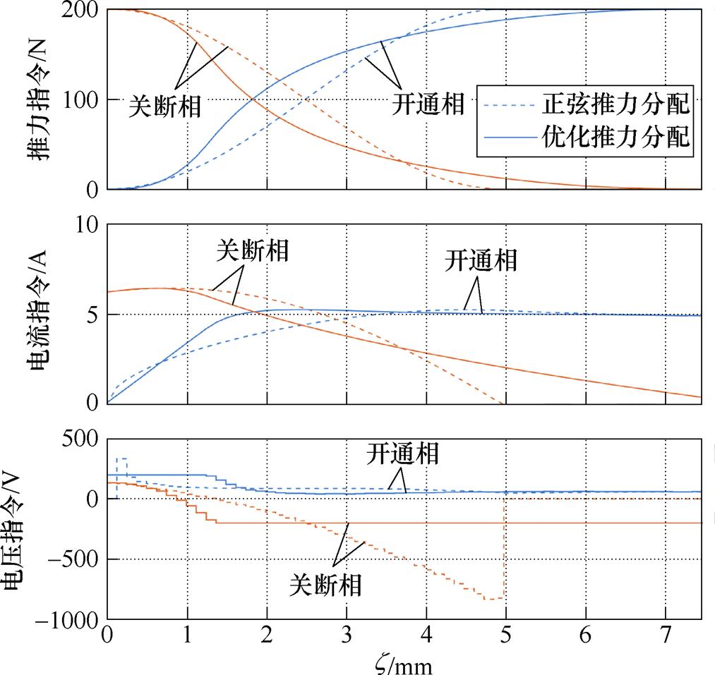
图7 正弦、优化推力分配函数及对应推力、电流、电压波形
Fig.7 Optimized force sharing function and the corresponding current and voltage waveforms
可见,正弦推力分配函数在电感最大位置附近处存在较大的电流变化率,所需的相电压远远超过直流电压;在后者有限的情况下,实际电流无法跟踪指令值。而所设计的优化推力分配函数由于考虑了直流电压约束,能够较好地克服这一缺陷。
控制PMSM进行恒定速度往复运动,考察各控制方法所产生的推力波动大小。其中,各相电流由驱动回路上的霍尔电流传感器测量得到,而实时推力则由测得的位置和电流根据辨识所得的电机推力参数计算得到。设置速度大小为0.8 m/s,恒定电流控制的电流参考值为6 A,两种推力分配控制中推力指令为200 N,实验结果如图8所示。
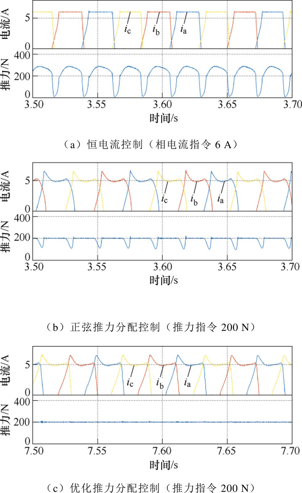
图8 恒定速度(0.8 m/s)下不同控制方式比较
Fig.8 Comparison of different control methods under constant velocity (0.8 m/s)
可以得到以下观测结果:
(1)令电流为恒定值所产生的推力波动很大,此现象一是由于电机自身的复杂推力特性使得恒定电流无法在不同位置产生恒定转矩;二是由于有限的直流电压使得电流上升过程需要时间,期间存在推力跌落。
(2)对于正弦推力分配控制,由于电流指令由恒定推力反求得到,能够在大部分区间内产生恒定推力,但仍存在电流无法跟踪参考值的部分区间。
(3)所求解的优化推力分配函数能够同时克服上述两个问题,从而实现最小的推力波动。
首先考虑单自由度(阻尼)控制的情况。令PMSM工作在位置环,位置指令为周期1.6 s、幅值0.3 m的正弦波。对于恒定电流控制,令电流指令与电机速度成正比,比例系数为6 A/(m/s),且推力方向总是与速度方向相反;对于推力分配控制,阻尼系数设置为160 N/(m/s),实验结果如图9所示。可见,在阻尼控制工况下,由于优化推力分配函数的计算考虑了直流有限的约束条件,基于优化推力分配的控制能够在一、三象限内实现推力跟踪和最小的推力波动,从而满足波浪发电阻尼控制的要求。
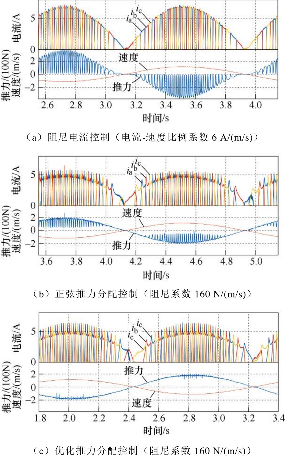
图9 用于波浪发电阻尼控制的不同控制方式比较(位置轨迹为幅值0.3 m,周期1.6 s的正弦波)
Fig.9 Comparison of different LSRG controls to realize the damping control of WECs (the position profile is sinusoidal with an amplitude of 0.3 m and a period of 1.6 s)
进一步考察双自由度(谐振)控制的情况,这时只考察推力分配控制,电机的阻尼和弹性系数分别设置为120 N/(m/s)和400 N/m,实验结果如图10所示。可见,四象限推力分配函数方法可以在四象限内均能实现推力跟踪,满足波浪发电优化控制对电机运行的要求;其中,由于基于优化推力分配函数的方法具有更好的电流跟踪性能,其推力波动显著小于正弦推力分配函数。
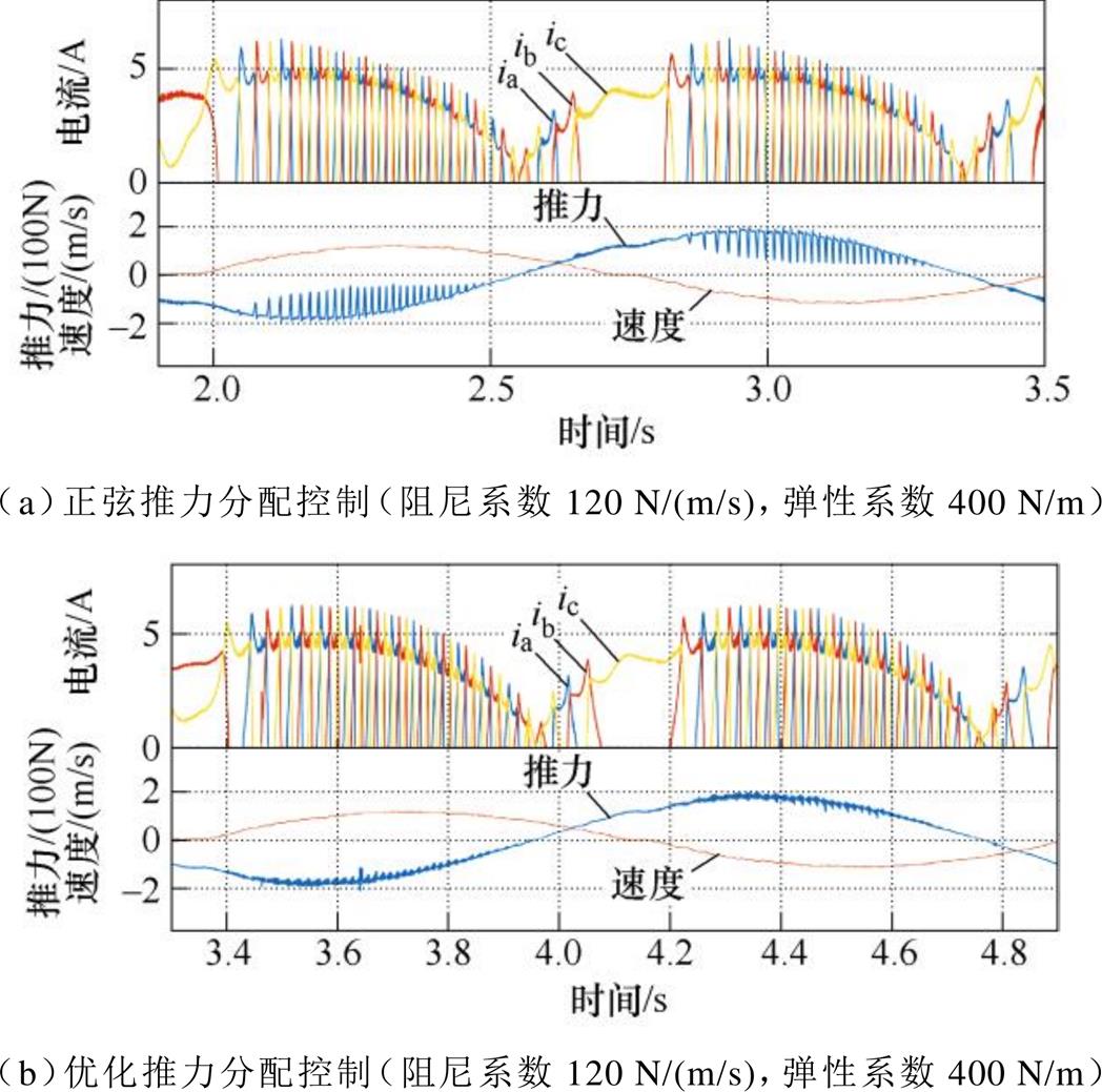
图10 用于波浪发电谐振控制的不同控制方式比较(位置轨迹为幅值0.3 m,周期1.6 s的正弦波)
Fig.10 Comparison of different LSRG controls to realize the reactive control of WECs (the position profile is sinusoidal with an amplitude of 0.3 m and a period of 1.6 s)
本文提出了一种将LSRG应用于波浪发电优化控制场合的四象限推力控制方法。设计了考虑直流电压有限这一约束条件的优化推力分配函数,能够有效地限制电流变化率,并给出了具体的四象限下推力分配策略。搭建了一个6/4极LSRG-PMSM对拖平台,通过PMSM模拟了匀速运行工况和波浪发电阻尼控制和谐振控制工况,对所提出的方法进行了实验验证。结果表明,所提出的控制策略能够实现四象限下推力跟踪的功能,并且与传统的恒电流控制和正弦推力分配控制相比,具有最小的推力波动。因此,所提出方法能够满足波浪发电优化控制对LSRG控制的要求。
参考文献
[1] 李飞宇, 顾延勋, 魏繁荣, 等. 波浪能液压发电系统灵活接入下的孤岛微电网细粒化调度[J]. 电工技术学报, 2023, 38(13): 3499-3511.
Li Feiyu, Gu Yanxun, Wei Fanrong, et al. Fine- grained dispatching of isolated microgrids under flexible access of wave energy hydraulic power generation system[J]. Transactions of China Elec- trotechnical Society, 2023, 38(13): 3499-3511.
[2] 黄宣睿, 林泽川, 肖曦. 双浮体直驱波浪发电装置建模分析与基于模型预测控制的能量提取算法研究[J]. 电工技术学报, 2024, 39(2): 445-454.
Huang Xuanrui, Lin Zechuan, Xiao Xi. Modelling and analysis of the two-body direct-drive wave energy converter and optimal energy extraction method based on model predictive control[J]. Transactions of China Electrotechnical Society, 2024, 39(2): 445-454.
[3] Pan Jianfei, Zou Yu, Cheung N, et al. On the voltage ripple reduction control of the linear switched reluctance generator for wave energy utilization[J]. IEEE Transactions on Power Electronics, 2014, 29(10): 5298-5307.
[4] 洪岳, 潘剑飞, 刘云, 等. 直驱波浪能发电系统综述[J]. 中国电机工程学报, 2019, 39(7): 1886-1900.
Hong Yue, Pan Jianfei, Liu Yun, et al. A review on linear generator based wave energy conversion systems[J]. Proceedings of the CSEE, 2019, 39(7): 1886-1900.
[5] Pan Jianfei, Zou Yu, Cao Guangzhong. Investigation of a low-power, double-sided switched reluctance generator for wave energy conversion[J]. IET Rene- wable Power Generation, 2013, 7(2): 98-109.
[6] Wang Daohan, Shao Chunlei, Wang Xiuhe. Design and performance evaluation of a tubular linear switched reluctance generator with low cost and high thrust density[J]. IEEE Transactions on Applied Super-conductivity, 2016, 26(7): 1-5.
[7] Du Jinhua, Liang Deliang, Liu Xinzheng. Per- formance analysis of a mutually coupled linear switched reluctance machine for direct-drive wave energy conversions[J]. IEEE Transactions on Mag- netics, 2017, 53(9): 1-10.
[8] Ringwood J V, Bacelli G, Fusco F. Energy- maximizing control of wave-energy converters: the development of control system technology to optimize their operation[J]. IEEE Control Systems Magazine, 2014, 34(5): 30-55.
[9] Xiao Xi, Huang Xuanrui, Kang Qing. A hill- climbing-method-based maximum-power-point-trackingstrategy for direct-drive wave energy converters[J]. IEEE Transactions on Industrial Electronics, 2016, 63(1): 257-267.
[10] Faedo N, Olaya S, Ringwood J V. Optimal control, MPC and MPC-like algorithms for wave energy systems: an overview[J]. IFAC Journal of Systems and Control, 2017, 1: 37-56.
[11] Huang Xuanrui, Sun Kai, Xiao Xi. A neural network-based power control method for direct-drive wave energy converters in irregular waves[J]. IEEE Transactions on Sustainable Energy, 2020, 11(4): 2962-2971.
[12] Cantarellas A M, Remon D, Rodriguez P. Adaptive vector control of wave energy converters[J]. IEEE Transactions on Industry Applications, 2017, 53(3): 2382-2391.
[13] 费晨, 颜建虎, 汪盼, 等. 基于改进的转矩分配函数法的开关磁阻电机转矩脉动抑制[J]. 电工技术学报, 2018, 33(增刊2): 394-400.
Fei Chen, Yan Jianhu, Wang Pan, et al. Torque ripple suppression of switched reluctance motor based on modified torque sharing function[J]. Transactions of China Electrotechnical Society, 2018, 33(S2): 394-400.
[14] 蔡燕, 居春雷, 王浩楠, 等. 开关磁阻电机的新型直接瞬时转矩控制方法及其高效率运行[J]. 电工技术学报, 2022, 37(18): 4625-4637.
Cai Yan, Ju Chunlei, Wang Haonan, et al. A new direct instantaneous torque control method of switched reluctance motor and its high efficiency operation[J]. Transactions of China Electrotechnical Society, 2022, 37(18): 4625-4637.
[15] 马铭遥, 余发, 杨晴晴, 等. 基于注入分段式谐波电流抑制开关磁阻电机转矩脉动的控制策略[J]. 中国电机工程学报, 2018, 38(1): 285-291, 366.
Ma Mingyao, Yu Fa, Yang Qingqing, et al. Control strategy of minimizing torque ripples of the switched reluctance motor by injecting piecewise harmonic currents[J]. Proceedings of the CSEE, 2018, 38(1): 285-291, 366.
[16] Huang Xuanrui, Lin Zechuan, Xiao Xi. Four-quadrant force control with minimal ripple for linear switched reluctance machines[J]. CES Transactions on Elec- trical Machines and Systems, 2020, 4(1): 27-34.
[17] Ilic'-Spong M, Marino R, Peresada S, et al. Feedback linearizing control of switched reluctance motors[J]. IEEE Transactions on Automatic Control, 1987, 32(5): 371-379.
[18] 熊冬勤. 海浪发电直线开关磁阻电机优化设计及其性能分析[D]. 沈阳: 沈阳工业大学, 2021.
Abstract Linear switched reluctance generators (LSRG) are promising candidates for direct-drive wave energy converters (WECs) due to their low cost and high reliability. The generator should be properly controlled to actively change the wave-body interactions to improve the wave energy capture efficiency. It requires a two-layer, cascaded control scheme: an upper layer is the energy-optimizing controller providing a force command, and a lower layer is the generator controller tracking this command. Because the WEC oscillates with waves, its velocity is bi-directional. Meanwhile, the optimal force is usually not strictly passive but contains reactive components. Consequently, the LSRG should be controlled to track the desired force in all four quadrants. However, existing LSRGs for WECs typically operate with a fixed on-off angle, limiting their ability for energy-optimizing control. Much research focuses on torque (force) tracking with ripple minimization with constant force and constant speed for switched reluctance motors. There is a gap in experimental testing under WEC-specific operation conditions.
This paper proposes a four-quadrant force-sharing strategy for LSRGs for WECs. First, two classic energy-optimizing control strategies, i.e., damping control and reactive control, are introduced, with output force commands linear to the body’s velocity and displacement. Next, the basic model of LSRG is derived, and an exponential-sinusoidal model describing the position-current-force characteristics is adopted. Two basic control methods of LSRG, the constant-current control and the sinusoidal force-sharing control, are introduced. The constant-current control maintains a fixed phase current, resulting in a fluctuating force due to the nonlinear force characteristics. The sinusoidal force-sharing control distributes the total force command into two phases according to a sinusoidal function. Ideally, this produces a constant total force. However, the DC voltage is limited, and an arbitrary current command cannot be tracked in time, so the total force also contains ripples. Therefore, an optimized force-sharing function is proposed to minimize current loss within the constraints of DC voltage and total force command. A discrete force-sharing function can be solved, stored in the controller, and implemented in real-time. Finally, a force distribution table for all four quadrants is derived for implementation.
An experimental platform simulating WEC operation is established, with an LSRG as the generator and a permanent-magnet synchronous motor (PMSM) as the prime mover. The parameters of the LSRG, especially the position-current-force characteristics, are identified through fixed-position excitation experiments. Then, three tests are conducted: (1) the classic, constant-velocity test, (2) the WEC’s damping control test, and (3) the WEC’s reactive control test. For each test, constant current control, sinusoidal force sharing, and optimized force sharing are compared in terms of total force. It is verified that under all the conditions, the optimized force-sharing strategy outperforms the constant-current control and sinusoidal force-sharing control, achieving the desired force with minimal ripples. The proposed method meets the energy-optimizing control requirements for WECs, as the changing rate of current profiles is constrained by considering DC voltage.
keywords:Wave energy conversion, linear switched reluctance generator, force ripple minimization
DOI: 10.19595/j.cnki.1000-6753.tces.230514
中图分类号:TM619
国家重点研发计划(2020YFE0205400)和国家自然科学基金(U1806224, 51977008)资助项目。
收稿日期 2023-04-22
改稿日期 2023-07-26
林泽川 男,1996年生,博士研究生,研究方向为波浪发电技术、开关磁阻电机控制等。E-mail: zechuanlin@126.com
肖 曦 男,1973年生,博士,教授,研究方向为永磁电机控制、电力电子技术、可再生能源技术等。E-mail: xiao_xi@tsinghua.edu.com(通信作者)
(编辑 陈 诚)