 为输入侧支撑电容,
 为输出侧滤波电容,
 为储能电感,n为高频隔离变压器电压比,
 为输入电压,
 为输出电压,u1为变压器一次侧H桥交流侧输入电压,
 为变压器二次侧H桥交流侧输出电压,
 为变压器一次侧电感电流,
 为变压器二次侧H桥直流侧输出电流,
 为负载电流。
摘要 该文以双有源全桥(DAB)DC-DC变换器为主要研究对象,针对传统比例积分控制动态响应慢及采用既有预测控制对量测噪声和参数敏感的缺陷,提出一种基于无电流传感器模型预测控制(CS-MPC)策略。首先构建双有源全桥DC-DC变换器的预测模型,分别针对变换器启动阶段与暂态过程提出基于模型预测控制(MPC)的动态优化策略;然后定量分析DAB变换器对模型参数和采样精度的敏感性,结合卡尔曼滤波算法构建其状态空间模型,在无电流传感器的情况下实现系统的鲁棒预测控制;最后在实验样机上通过实验验证所提方法的有效性。实验结果表明:与传统控制策略相比,所提方法能够实现低电流应力下的快速启动,且动态响应性能明显改善。此外,所提方法无需电流传感器数据,即对测量噪声脱敏;在参数变化下的鲁棒性能较传统预测控制显著提升。
关键词:双有源全桥DC-DC变换器 模型预测控制 动态响应提升 无电流传感器控制 鲁棒控制
随着新能源发电、电气化交通、储能系统等发展日渐成熟,电力系统正进入“源-网-荷-储”协调优化运行的新阶段。其中,基于电力电子器件的能源路由器能灵活接入和高效利用多种新能源,在“源-网-荷-储”协同系统中可以实现能量的多向传输和主动调配,已成为新型电力系统的核心装备[1-2]。而双有源全桥(Dual Active Bridge, DAB)DC-DC变换器因具备功率密度高、能量双向传输、天然的电气隔离及易于实现软开关等优势[3-6],已被广泛应用于电动汽车[7]、储能[8]、微电网[9]以及新能源发电[10]等能量变换系统,并逐渐成为能源路由器直流侧的重要拓扑之一[11-12]。
新型电力系统中,高比例新能源的接入导致电力系统工况复杂多变,各类储能设备投切频繁。以上特点要求能源路由器必须具备良好的动态性能。传统PI控制下,受控制器等效低通滤波特性限制,DAB变换器系统的动态性能十分缓慢,已成为DAB变换器在各领域内动态提升的重要瓶颈。近年来,针对其动态性能提升的研究倍受学界关注。现存各类控制算法为提升控制性能往往将电流信号引入控制回路以提升系统的动态性能[13-15]。电流信号的引入需要模数转换模块,而通常其采样率需要至少高于开关频率4倍。DAB变换器的开关频率可高达几百kHz,这就意味着在实际工程应用中,引入新的电流数据对模数转换模块的性能有极高的要 求[16-17]。针对此问题,文献[18]提出了一种考虑电感能量变化的能量前馈方案,无需电流传感器便可稳定控制,但其增设积分环节降低了系统的动态响应速度。文献[19]基于非线性扰动观测器提出了一种负载电流前馈的DAB变换器无电流传感器控制策略,降低了积分环节对系统动态响应速度的影响。文献[20]提出了一种无电流传感器均流控制策略,能够在无电流传感器的情况下,实现各功率模块的均流控制且拥有较好的动态性能。但该控制策略只针对于双重移相调制下的独立输入并联输出的DAB变换器系统,无法应用于单机DAB变换器系统,具有一定局限性。
此外,作为一种特殊的动态过程,DAB变换器系统在启动阶段的速度与电流应力大小呈正相关。而过高的电流应力则会导致开关器件以及变压器等磁性元件的热损坏,严重影响变换器性能与使用寿命。文献[21-23]提出了两阶段式的启动策略:第一阶段变压器一次电压脉宽开环缓慢增大至额定值;第二阶段切入闭环控制,参考电压缓慢上升至额定值。此方案虽然限制了电流应力,但参数整定复杂且并未充分利用载流能力,启动速度缓慢。
综上所述,现存各类控制策略无法在电流传感器的情况下兼顾理想的启动性能与动态性能。针对此问题,本文开展对模型预测控制(Model Predictive Control, MPC)在DAB变换器系统中应用的研究,以解决上述控制策略的缺陷。
作为一种先进控制方案,模型预测控制易于实现系统多目标优化问题,并具备优异的动态性能,适用于DAB变换器系统。针对模型预测控制在DAB变换器系统中的应用,文献[24]提出了一种基于离散时间模型的预测控制DAB转换器的查表方法,提高了系统的动态响应能力。但此方法需要在每个周期内进行大量计算,难以应用于实际工程。文献[25]提出了一种应用于插电式混合动力汽车的模型预测控制策略,使系统具有更快的动态响应能力与更低超调,但其只适用于特定充电电池模型,不具有可移植性。相较于传统PI控制,模型预测控制策略能有效提升DAB变换器系统的动态响应能力。但是,现有研究将模型预测控制应用于DAB变换器系统时,未考虑模型预测控制策略对模型参数精度以及采样精度的高要求。因此,其控制稳定性往往并不理想。本文将深度分析模型预测控制策略对模型参数与采样噪声的敏感性,并提出一种具有高动态性能的无电流传感器鲁棒预测控制策略。
基于上述问题,本文提出了基于模型预测控制的DAB变换器低电流应力快速启动策略。所提方法无需复杂调参过程,且在低电流应力限制下大大提高了DAB变换器的启动速度。
同时,本文提出了基于模型预测控制的DAB变换器暂态优化控制策略。所提方法基于单重移相调制,分别求得DAB变换器暂稳态过程的最优移相比解析解,实现简单,无需遍历计算,大大提升了系统的动态响应性能。
本文通过系统状态变量的重构与观测系数的改进,使系统实现了基于卡尔曼滤波算法的无输出电流传感器的鲁棒控制。所提方法克服了经典模型预测控制策略对模型参数与采样精度的强依赖性,使系统在采样噪声于模型参数失配工况下仍可稳定运行。
双有源全桥DC-DC变换器拓扑如图1所示。图中,S1~S4为变压器一次侧H桥功率开关器件,S5~S8为变压器二次侧H桥功率开关器件, 为输入侧支撑电容,
 为输出侧滤波电容,
 为储能电感,n为高频隔离变压器电压比,
 为输入电压,
 为输出电压,u1为变压器一次侧H桥交流侧输入电压,
 为变压器二次侧H桥交流侧输出电压,
 为变压器一次侧电感电流,
 为变压器二次侧H桥直流侧输出电流,
 为负载电流。
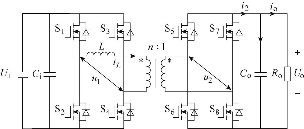
图1 双有源桥DC-DC变换器拓扑
Fig.1 Topology of dual active bridge DC-DC converters
单重移相(Single-Phase-Shift, SPS)调制策略通过改变一次、二次侧开关器件驱动信号的移相比,从而控制一次、二次电流与电压的工作波形,进而控制变换器传输功率的大小和方向。以功率正向传输、 情况为例进行分析,SPS调制下DAB变换器开关脉冲信号及电压电流波形如图2所示。Si为第i个开关管的开通信号,D为一次、二次侧变换器驱动信号的移相比(即开关管S1与S5驱动信号之间的相移量),
 为一个信号周期。
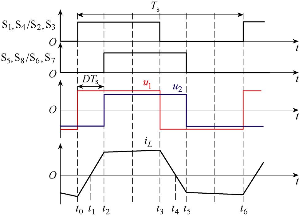
图2 单重移相调制下DAB变换器开关及电压电流波形
Fig.2 Pulse sequence and operating waveforms of DAB converters under SPS control
分析不同工作状态下的电流通路,可得各时段电感电流表达式为
 (1)
(1)
根据电感电流的对称性可得,变换器在t0~t3时刻和t3~t5时刻内的传输功率相同,由此可得传输功率表达式为
 (2)
(2)
相较于单重移相调制策略,扩展移相(Extended- Phase-Shift, EPS)调制策略在外移相比 (即开关管S1与S5驱动信号之间的相移量)的基础上增设了内移相比
 (即开关管S1与S3驱动信号之间的相移量)。以正向功率传输为例,依据内外移相比的大小关系,扩展移相调制策略下DAB变换器可分为两类工作模式。扩展移相调制下DAB变换器电压电流波形如图3所示。
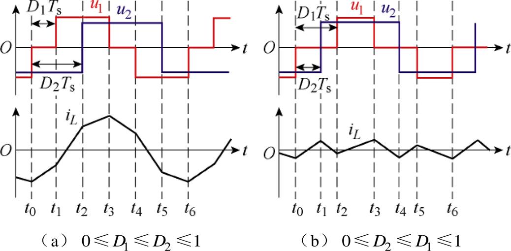
图3 扩展移相调制下DAB变换器电压电流波形
Fig.3 Voltage and current waveforms of DAB converters under EPS control
推导过程同单重移相调制,根据各模式下的电压电流特性,可以得出在不同的扩展移相调制模式下DAB变换器的传输功率方程为
 (3)
(3)
模型预测控制策略主要包含预测模型、滚动优化与反馈校正三个部分。将模型预测控制(MPC)策略应用于DAB变换器系统,首先需要构建双有源全桥DC-DC变换器的数学模型。
单重移相调制策略下DAB变换器的工作状态如第1节所述,其输出功率如式(2)所示。首先以功率正向传输为例,在理想的稳态运行情况下,负载功率即为变换器全部输出功率,且稳态时输出电压恒定,可得变压器二次侧H桥直流侧输出电流为
 (4)
(4)
由基尔霍夫电流定律可得,输出端节点的电流微分方程为
 (5)
(5)
式中,iC为输出电容电流。基于一阶前向欧拉法,可通过式(5)得到DAB变换器输出电压的离散化模型为
 (6)
(6)
将式(6)代入式(5),可得DAB变换器输出电压预测模型为
 (7)
(7)
其中

式中, 为下一时刻变换器输出电压预测值;
 、
、 、
、 、
、 分别为当前时刻变换器的负载电流、移相比、输入电压、输出电压。
其他移相调制策略下,本节所提的预测模型建立方法同样适用。以扩展移相调制策略为例,只需对式(7)中的第二项进行修改,即可得到其输出电压的预测模型为
 (8)
(8)
式中, 对应扩展移相调制的两种工作模式,
 ,具体为
,具体为
 (9)
(9)
在启动阶段,为解决电流应力与启动速度间的矛盾,实现DAB变换器低电流应力下的快速启动,需要多个控制量以便进行系统的多目标优化,因此选用扩展移相调制策略。
在得到DAB变换器的预测模型后,需要构建相应的代价函数。启动阶段,优化目标为将输出电压上升至给定参考值,使系统尽快进入稳态。根据输出电压预测模型,可建立代价函数为
 (10)
(10)
式中, 为输出电压的设定参考值。设DAB变换器的传输功率与电流应力的理论最大值为参考值,即
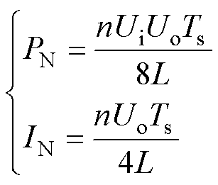 (11)
(11)
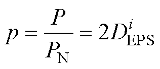
为便于计算,将传输功率进行标幺化处理得
 (12)
(12)
将式(12)代入式(8)得
 (13)
(13)
以 ,工作模式为a时为例,代价函数
 为闭区间[0, 1]内关于传输功率
 的函数,对其求导可得
 (14)
(14)
启动阶段,输出电压并未上升至稳态参考值,因此 恒大于
恒大于 ,因此代价函数值与
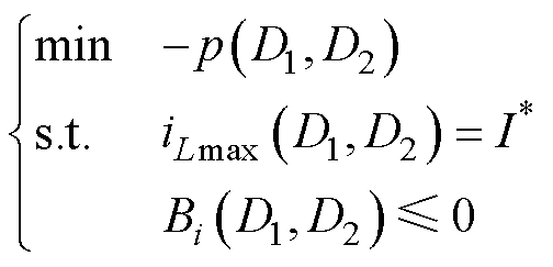
 呈负相关。为便于优化,代价函数最小值的求解可等价为传输功率最大值的求解。在电流应力限制下,传输功率最大值求解可改写为
 (15)
(15)
式中, 为电流应力给定值;
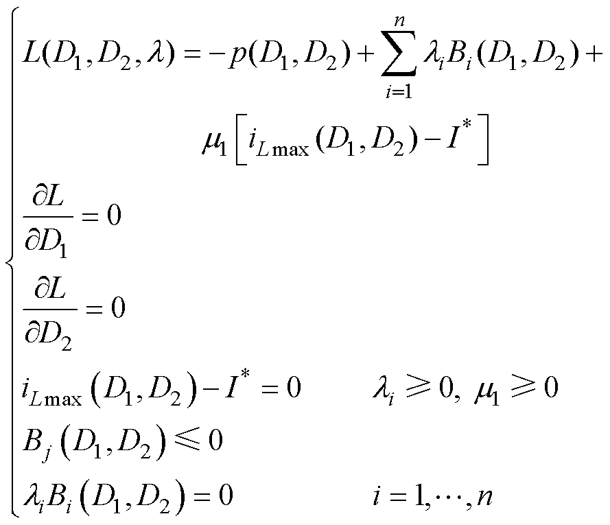
 为a模式下移相比约束范围。该等式约束优化问题可由卡罗需-库恩-塔克条件(Karush-Kuhn-Tucker, KKT)求解为
 (16)
(16)
式中, 为拉格朗日函数;
 为KKT乘子;
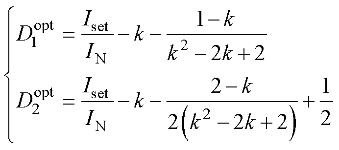
 为拉格朗日乘子。求解式(16)可得最优移相比为
 (17)
(17)
式中,Iset为给定电流限值。
暂态过程中,双有源全桥DC-DC变换器的首要控制目标是准确稳定地跟踪输出电压的参考值,电流应力与优化目标并不矛盾,为简化实现,采用单重移相调制策略,代价函数仍为式(10)。
根据式(7)可知,在DAB变换器的模型预测控制策略中,移相比 为控制系统的输入控制变量。一般认为,在实际工况下,
 。由此,代价函数式(10)的最小值的求解问题即为
求取最优移相比 ,即
,即
 (18)
(18)
结合式(7)可得,代价函数 为闭区间 [-0.5, 0.5]内关于移相比
 的连续函数,对其求导可得
当 时
时
 (19)
(19)
当 时
时
 (20)
(20)
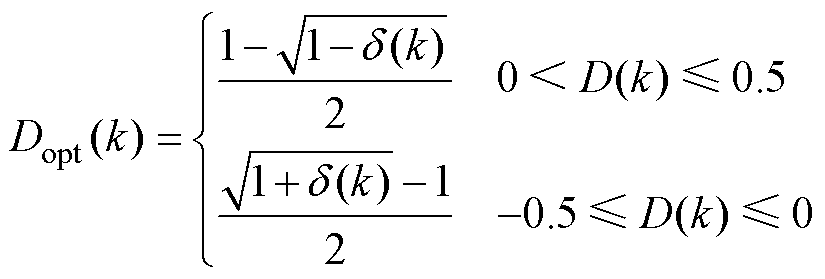
首先,由式(19)和式(20)可知,若代价函数在区间内存在极值点,必有 ,此时代价函数
 ,取最小值。将其代入式(7)可得最优移相比为
 (21)
(21)
其中
 (22)
(22)
其次,若代价函数在区间 内无极值点,则代价函数的最小值必在区间端点处取得。由式(7)可知,在区间
 内,输出电压
 与移相比
与移相比 呈正相关。若代价函数在区间
 内无极值点,则必为如下情况:①
 ,
, 恒成立,此时取
 ,代价函数取得最小值;②
 ,
, 恒成立,此时取
 ,代价函数取得最小值。
通过上述分析,可得单重移相调制策略下模型预测控制流程,如图4所示。首先,通过比较 输出电压
输出电压 与参考电压
与参考电压 的大小关系,可缩小求解范围,简化计算。若
 ,由于
,由于 为关于
为关于 的单调递增函数,则
 ,
, 恒成立,
恒成立, 恒成立。
恒成立。
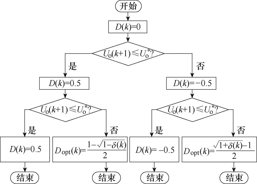
图4 基于单重移相调制策略的模型预测控制算法
Fig.4 Algorithm of model predictive control based on single-phase-shift modulation
因此,最优移相比在区间 [0, 0.5] 内取得。同理可得,若 ,则最优移相比在区间[-0.5, 0] 内取得。
DAB变换器的输出电压预测模型是基于预测模型实现的最优控制响应与实际系统一致的假设所建立的[26]。而在实际的DAB变换器电气系统中,存在模型参数误差和传感器采样误差,影响着模型预测控制系统的预测性能。由于双有源全桥DC-DC变换器模型预测控制的预测性能对模型参数与采样精度的高度依赖性,针对其鲁棒性提升的研究具有重大的实际工程意义。本节在第2节所提的模型预测控制策略的基础上,提出了一种基于卡尔曼滤波算法的无电流传感器的鲁棒预测控制策略,可有效改善经典模型预测控制策略应用于DAB变换器时抗噪声能力差的问题。
由式(7)可得,电路中储能电感、输出侧电容的模型参数误差直接影响预测模型的准确性。 为控制器中k+1时刻的输出电压,
 为输出电压的参考值,
 和
和 分别为控制器中储能电感与输出侧电容的模型值。定义
 为实际电路中k+1时刻的输出电压,
 、
、 分别为考虑误差在内的实际电路中储能电感参数和输出电容参数。假定k时刻控制器的输出电压值即为实际值,则控制器k+1时刻的输出电压如式(7)所示,而实际电路中k+1时刻输出电压为
 (23)
(23)
系统稳定运行时,可认为
 (24)
(24)
将式(7)、式(23)与式(24)联立可得
 (25)
(25)
由式(25)可以看出,储能电感参数误差是影响系统输出电压偏差值的主导因素。当储能电感参数准确( )时,输出电压无偏差,不受输出电容参数误差的影响;当储能电感参数存在误差(
 )时,输出电压存在偏差,电容模型误差会影响输出电压。
由式(7)可知,除模型参数外,系统输入电压 、输出电压
、输出电压 、输出电流
、输出电流 的采样噪声也直接影响DAB变换器的预测模型的预测性能。
分析采样噪声对系统预测性能的影响,如图5所示[27]。在表1工况下,仅1.4%的采样误差即可引起移相比从-0.5~0.5的突变。因此,双有源桥变换器系统的模型预测控制策略对模型参数以及采样精度有着极高的要求,提升模型预测控制的鲁棒性势在必行。
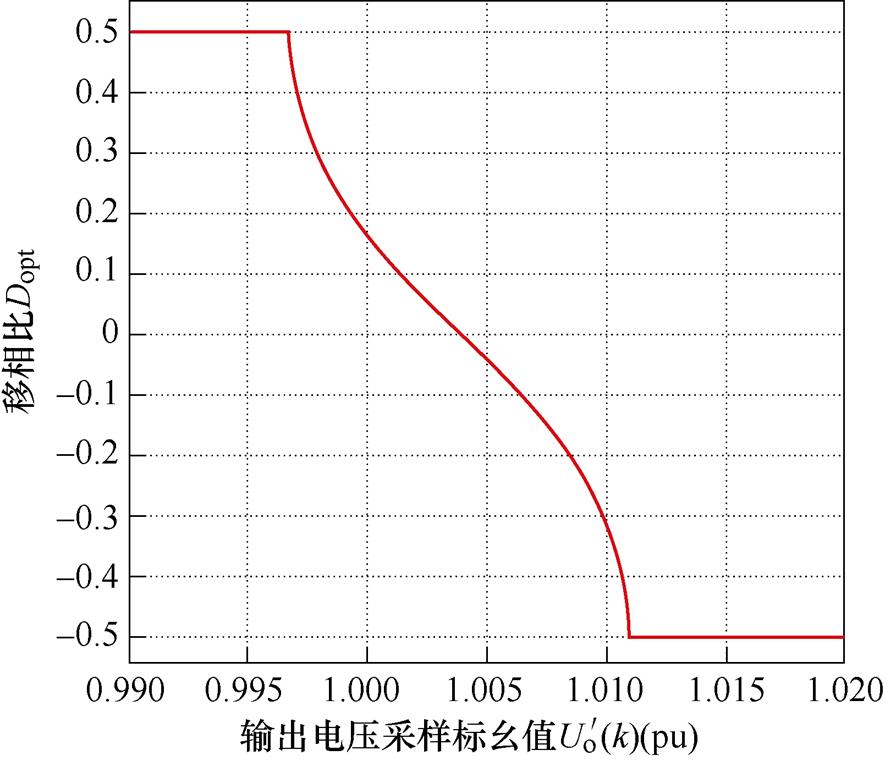
图5 移相比与输出电压采样标幺值的关系
Fig.5 Relationship between the phase-shift ratio and output voltage sampling per-unit value
鲁道夫·卡尔曼(Rudolf Emil Kalman)在1960年提出了一种离散数据线性滤波问题的递归算法,其利用线性系统状态方程,通过系统输入输出观测数据,对系统状态进行最优估计[28]。
将卡尔曼滤波算法应用于模型预测控制下的DAB变换器系统包含三个基本步骤。
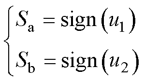
(1)建立DAB变换器系统离散状态空间模型。单重移相调制策略下双有源全桥DC-DC变换器的工作状态如第1节所述,定义切换函数为
 (26)
(26)
式中, 为符号函数,定义为
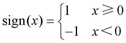 (27)
(27)
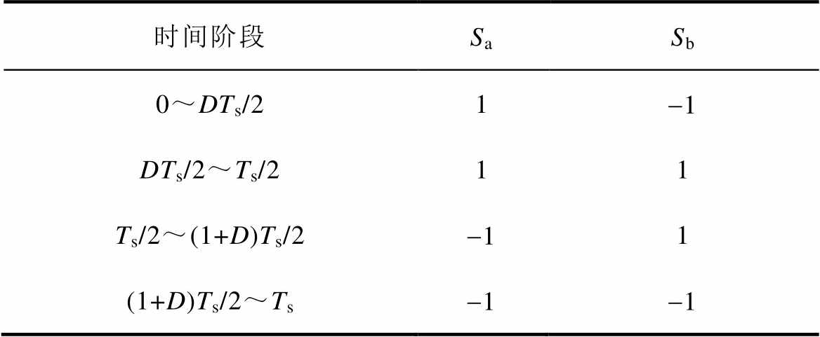
由此可得单重移相调制策略下双有源全桥DC-DC变换器工作状态与理想切换函数的关系,见表1。
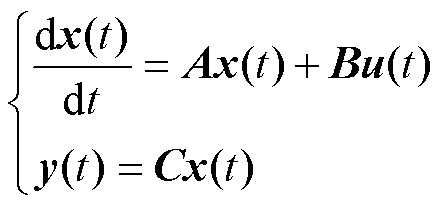
将DAB变换器的输出电流与输出电压作为状态变量,依据其工作特性建立状态空间方程为
表1 工作状态与切换函数之间的关系
Tab.1 Relationship between operating state and switching function
时间阶段SaSb 0~DTs/21-1 DTs/2~Ts/211 Ts/2~(1+D)Ts/2-11 (1+D)Ts/2~Ts-1-1
 (28)
(28)
其中, 为状态变量,表达式为
 (29)
(29)
式中, 为输出变量,代表变换器的输出电压
 。移相比为多元高阶形式,无法直接作为卡尔曼滤波的系统模型。因此,输入变量需要进行重构得
 (30)
(30)
经修正后,DAB变换器系统的线性离散随机状态方程为
 (31)
(31)
系统的测量方程为
 (32)
(32)
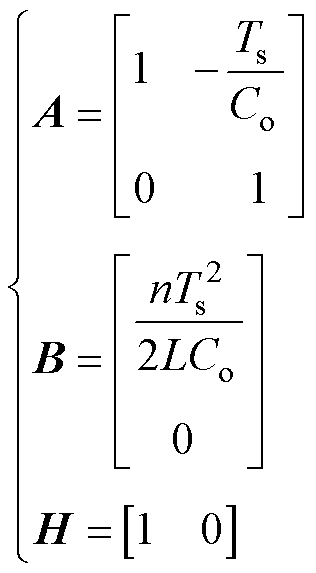
各系数矩阵为
 (33)
(33)
式中, 与
与 为随机变量矩阵,分别代表过程噪声与测量噪声。将输出电流的系数设置为1,即在模型中认为输出电流恒定不变,依靠卡尔曼滤波器矫正,实现无电流传感器闭环控制。
综上所述,可应用于卡尔曼滤波DAB变换器系统状态方程为
 (34)
(34)
(2)建立状态估计模型。不考虑噪声的影响时,DAB变换器系统的状态估计表达式为
 (35)
(35)
式中, 为预测模型所得的预测估计值;
 为测量方程所得的测量估计值,二者均包含噪声的影响。通过对两个估计值的加权平均,可得最终估计值
 ,其表达式为
 (36)
(36)
式中, 为权重系数矩阵。将卡尔曼增益
 代入式(36)可得最终状态估计表达式为
 (37)
(37)
(3)构建控制方案。输入重构后的控制量,卡尔曼滤波器输出状态变量的估计值为 和
和 ,使用估计值代替测量值
 和
和 ,同输入电压
 一并作为输出电压预测模型的输入控制量,完成移相比优化。整个控制方案框图如图6所示。
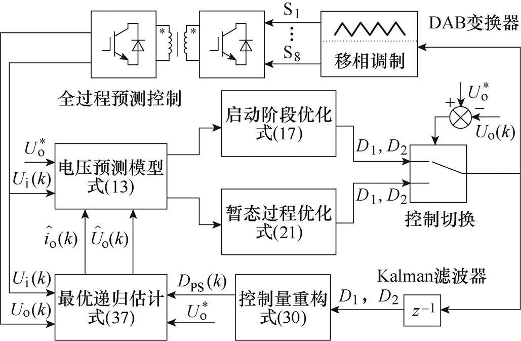
图6 基于卡尔曼滤波的无电流传感器鲁棒预测控制框图
Fig.6 Block diagram of current sensorless robust predictive control based on Kalman filter
为验证所提控制策略及算法的正确性和有效性,本文搭建小功率DAB变换器系统样机进行实验。首先,分别进行所提启动策略以及无传感器鲁棒预测控制策略与传统控制策略的动态性能对比实验。其次,验证所提无传感器鲁棒预测控制策略在采样噪声及储能电感适配50%情况下的鲁棒性。小功率DAB变换器实验平台如图7所示。实验样机以Plexim公司的RT-Box快速控制原型为控制系统;输入电源为恩智公司的N3300系列可编程直流电源;DAB变换器的两个对称H桥由Imperix公司的PEB-SiC-8024半桥功率模块构成;变压器为Payton公司的T6000系列平面变压器;电感为I1000系列平面电感。实验平台主要电气参数见表2。
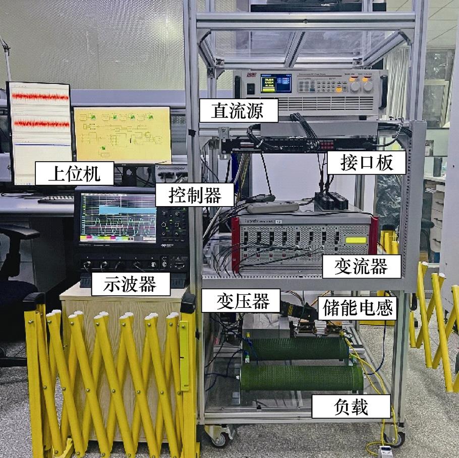
图7 DAB变换器实验平台
Fig.7 The DAB converter experimental platform
表2 DAB变换器实验平台参数
Tab.2 Parameters of the DAB converter experimental platform
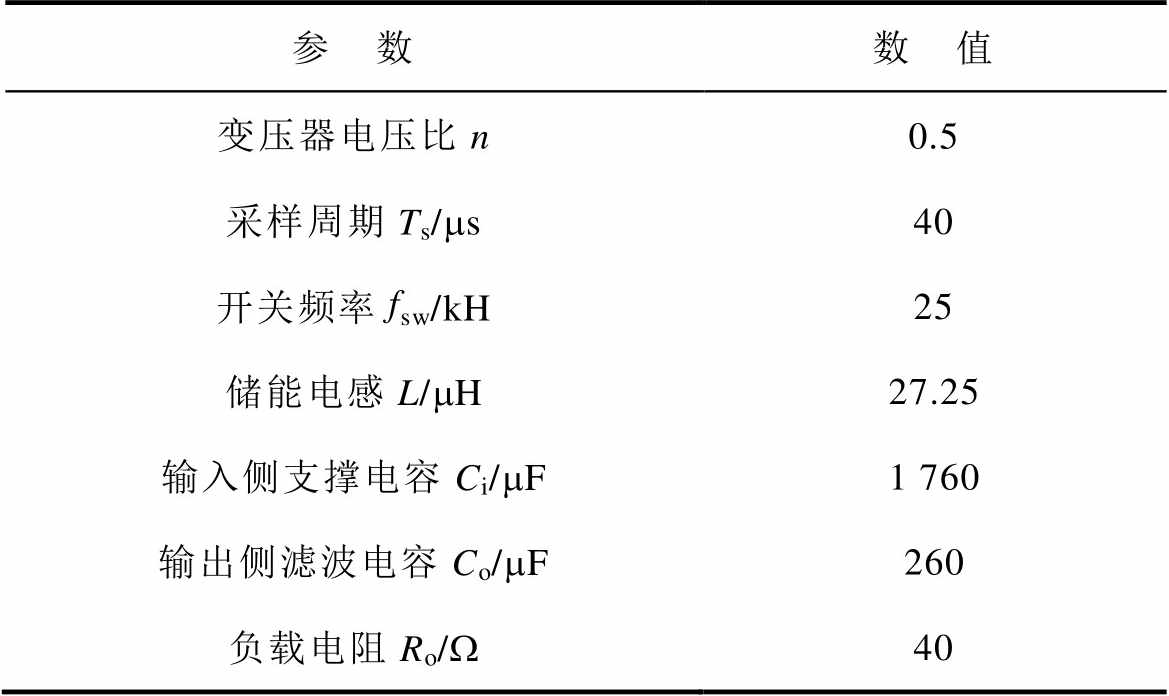
参 数数 值 变压器电压比n0.5 采样周期Ts/ms40 开关频率fsw/kH25 储能电感L/mH27.25 输入侧支撑电容Ci/mF1 760 输出侧滤波电容Co/mF260 负载电阻Ro/W40
实验中参考电压设为160 V,输入电压设为100 V。负载电阻为80 ,两种启动策略下变换器的电压电流波形如图8所示。传统两阶段启动策略启动时间为34 ms,电流应力为17 A;而在所提启动策略下,DAB变换器启动时间为16 ms,电流应力为17.1 A。所提策略在电流应力限制相同的情况下大幅提升了启动速度。
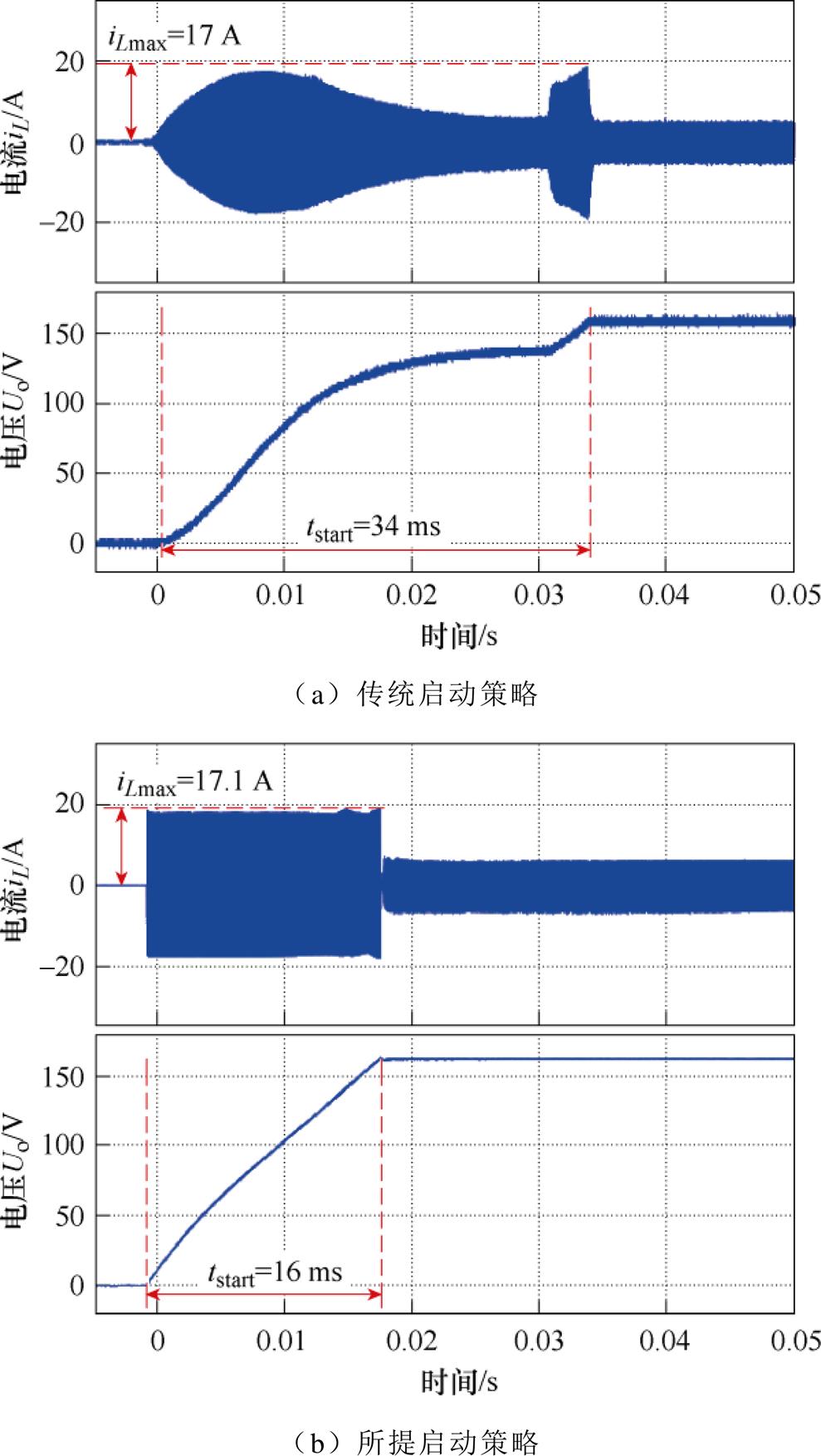
图8 两种方法启动性能对比
Fig.8 Strat-up performance comparison with two strategy
实验中参考电压设为160 V,输入电压设为100 V。当负载电阻从40 切换到80
切换到80 时,两种控制方法下变换器的电压电流波形如图9所示。实验结果显示,传统PI控制动态响应时间为17.6 ms;而在所提无电流传感器鲁棒预测控制策略下,系统动态响应时间为5 ms。
当负载电阻从80 切换到40
切换到40 时,两种控制方法下变换器的电压电流波形如图10所示。实验结果显示,传统PI控制策略下系统动态响应时间为11.7 ms;而在无电流传感器鲁棒预测控制下,系统动态响应时间为4.9 ms。
实验中参考电压设为160 V,负载电阻设为40 ,当输入电压由100 V切换为150 V时,两种控制方法下变换器的电压电流波形如图11所示。实验结果显示,传统PI控制策略下系统动态响应时间为12.5 ms;无电流传感器鲁棒预测控制下,系统动态响应时间为5.2 ms。
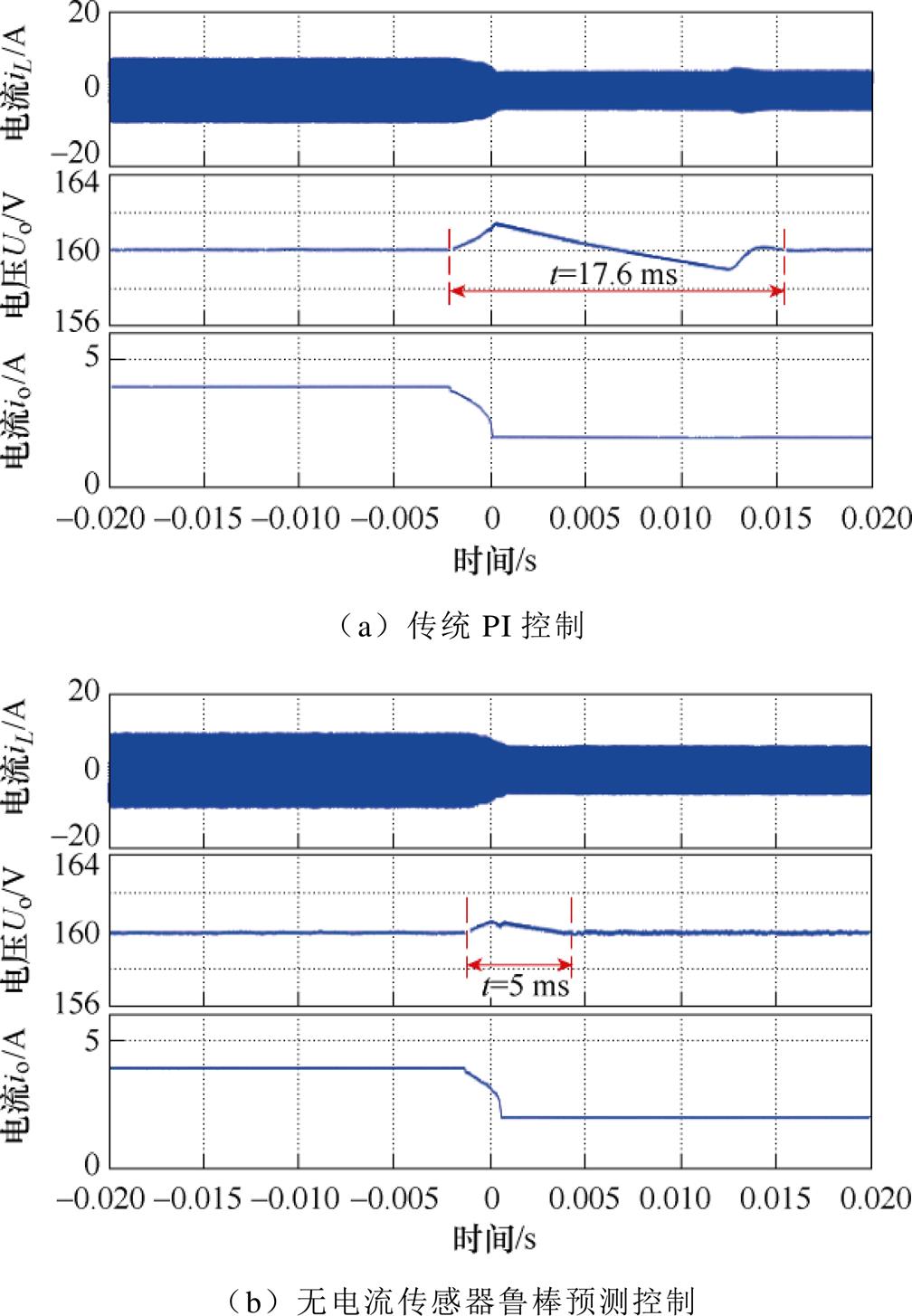
图9 负载电阻突增时两种方法暂态性能对比
Fig.9 Transient performance comparison when the load resistance increase
当输入电压由150 V切换为100 V时,两种控制方法下变换器的电压电流波形如图12所示。实验结果显示,传统PI控制策略下系统动态响应时间为17.2 ms;而在无电流传感器鲁棒预测控制下,系统动态响应时间为3.2 ms。
首先,验证所提方法对采样噪声的鲁棒性。本实验在输出电压的采样值上叠加一个均值为0、标准差为0.1的高斯白噪声,进行经典模型预测控制与所提控制方法的对比实验。因传统方法会在高压噪声工况下产生过电流,故实验中输入电压设为40 V,参考电压设为80 V,负载电阻设为40 。两种控制方法下变换器电压电流波形如图13所示,左侧为传统MPC结果,右侧为所提无电流传感器鲁棒预测控制结果。实验结果显示,此工况下经典模型预测控制方法移相比变化剧烈,电感电流应力最大值达26 A,无法实现稳定控制。所提方法电感电流应力最大值仅为5.1 A,明显提升了系统对采样噪声的鲁棒性,移相比变化稳定,电流电压纹波显著减小。
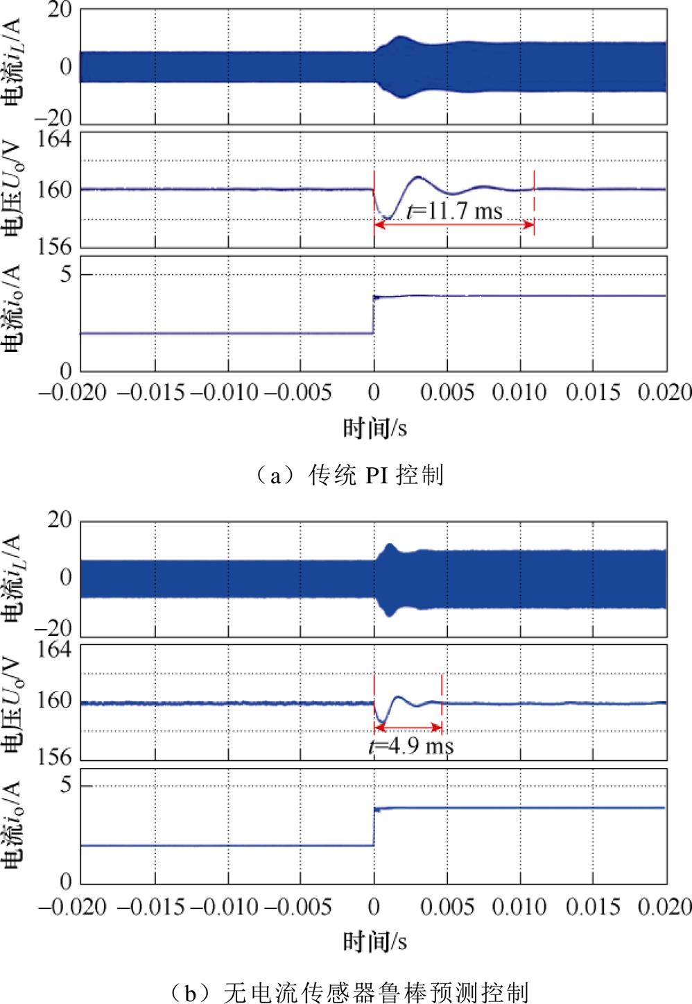
图10 负载电阻突减时两种方法暂态性能对比
Fig.10 Transient performance comparison when the load resistance reduction
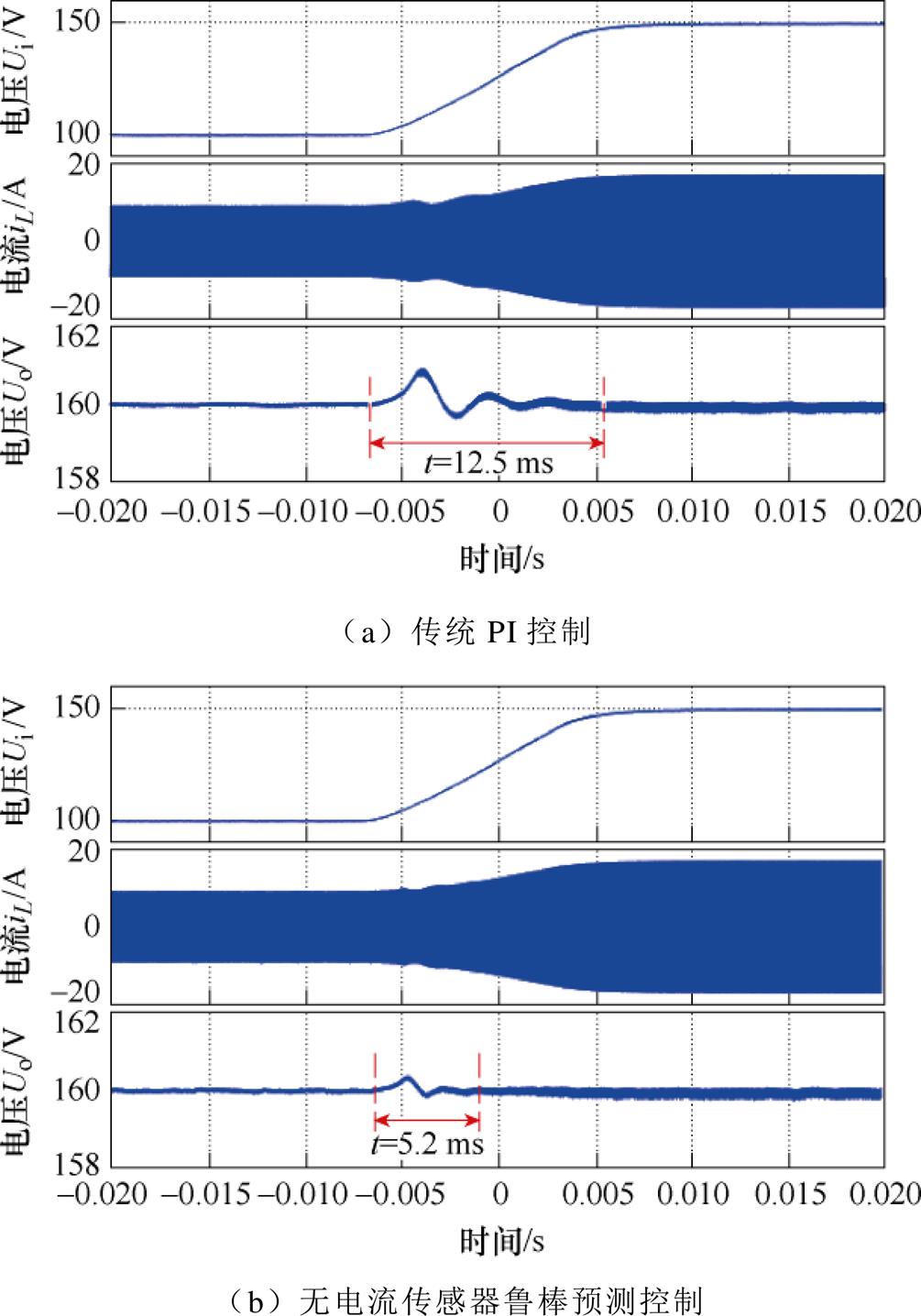
图11 输入电压突增时两种方法暂态性能对比
Fig.11 Transient performance comparison when the input voltage increase
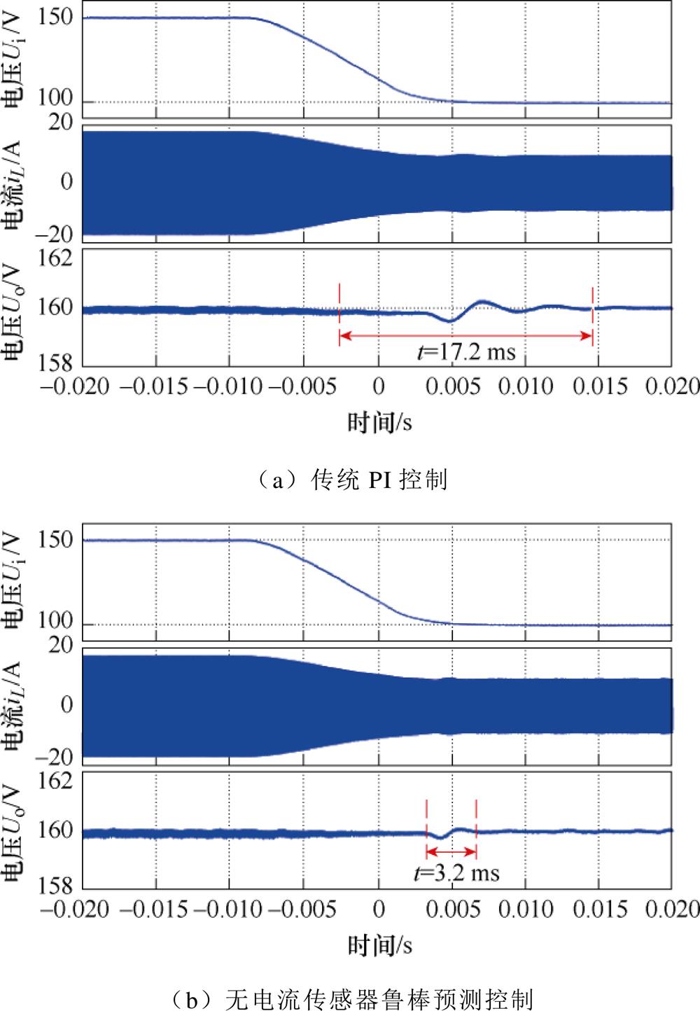
图12 输入电压突减时两种方法暂态性能对比
Fig.12 Transient performance comparison when the input voltage reduction
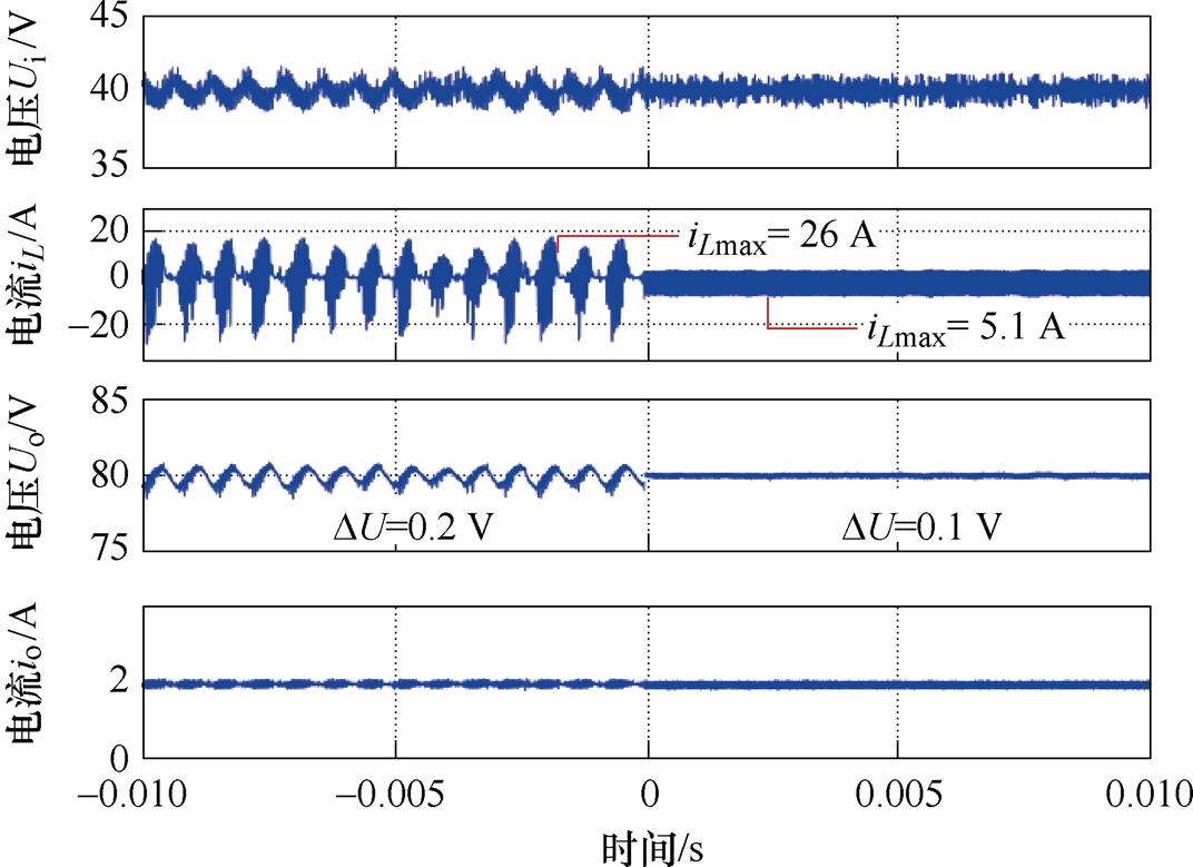
图13 模拟采样噪声干扰下两方法的性能对比
Fig.13 Performance comparison of two methods under simulated sampling noise
其次,在电感参数失配50%工况下进行经典模型预测控制与所提控制方法的对比实验。实验中输入电压设为40 V,参考电压设为80 V,负载电阻设为40 ,两种控制方法下变换器电压电流波形如图14所示,左侧为传统MPC结果,右侧为所提无电流传感器鲁棒预测控制结果。结果显示:经典模型预测控制策略下,电感参数的失配也将导致移相比的剧烈变化,无法实现稳定控制,电感电流应力最大值达27 A。而所提算法下电感电流应力最大值仅为5.4 A,能够保证系统的稳定运行,显著减小了输出电压与电感电流纹波。
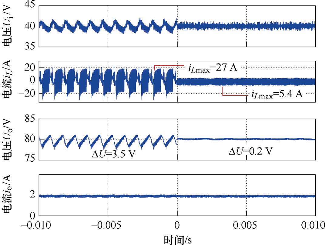
图14 电感失配50%时两方法的性能对比
Fig.14 Performance comparison of two methods when lnductor mismatch 50%
首先,本文分别提出了适用于启动阶段与暂态过程的全过程模型预测控制策略。其次,在上述全过程模型预测控制策略的基础上,本文通过对模型预测控制策略控制下的DAB变换器系统进行模型参数与采样精度的敏感性分析,提出了一种基于卡尔曼滤波的无电流传感器鲁棒预测控制策略。最后,经理论分析与实验验证,与传统控制方法对比,得到如下结论:
1)相较于传统两阶段启动策略与PI控制策略,所提全过程模型预测控制策略大幅提升了DAB变换器系统在启动速度与暂态过程的动态响应性能。
2)所提无电流传感器鲁棒预测控制策略无需电流传感器仍可保持良好动态性能,克服了模型预测控制策略参数依赖的缺陷,对模型参数误差及采样噪声鲁棒。
参考文献
[1] 安峰, 杨柯欣, 王嵩, 等. 基于模型前馈的双有源全桥DC-DC变换器电流应力优化方法[J]. 电工技术学报, 2019, 34(14): 2946-2956.
An Feng, Yang Kexin, Wang Song, et al. Current stress optimized scheme with model-based feed- forward for dual-active-bridge DC-DC converters[J]. Transactions of China Electrotechnical Society, 2019, 34(14): 2946-2956.
[2] 涂春鸣, 孟阳, 肖凡, 等. 一种交直流混合微网能量路由器及其运行模态分析[J]. 电工技术学报, 2017, 32(22): 176-188.
Tu Chunming, Meng Yang, Xiao Fan, et al. An AC- DC hybrid microgrid energy router and operational modal analysis[J]. Transactions of China Electro- technical Society, 2017, 32(22): 176-188.
[3] 王攀攀, 徐泽涵, 王莉, 等. 基于三重移相的双有源桥DC-DC变换器效率与动态性能混合优化控制策略[J]. 电工技术学报, 2022, 37(18): 4720-4731.
Wang Panpan, Xu Zehan, Wang Li, et al. A hybrid optimization control strategy of efficiency and dynamic performance of dual-active-bridge DC-DC converter based on triple-phase-shift[J]. Transactions of China Electrotechnical Society, 2022, 37(18): 4720-4731.
[4] 杨向真, 王锦秀, 孔令浩, 等. 电压不匹配运行条件下双有源桥变换器的效率优化方法[J]. 电工技术学报, 2022, 37(24): 6239-6251.
Yang Xiangzhen, Wang Jinxiu, Kong Linghao, et al. Efficiency optimization method of DAB converters under wide-voltage operating conditions[J]. Transa- ctions of China Electrotechnical Society, 2022, 37(24): 6239-6251.
[5] 高宇, 李若愚, 李林柘, 等. 三重移相调制模式下双有源变换器的直接功率控制[J]. 电工技术学报, 2022, 37(18): 4707-4719.
Gao Yu, Li Ruoyu, Li Linzhe, et al. Triple phase shift modulation-based direct power control strategy for a dual active bridge converter[J]. Transactions of China Electrotechnical Society, 2022, 37(18): 4707-4719.
[6] De Doncker R W A A, Divan D M, Kheraluwala M H. A three-phase soft-switched high-power-density DC/ DC converter for high-power applications[J]. IEEE Transactions on Industry Applications, 1991, 27(1): 63-73.
[7] Zhao Biao, Song Qiang, Liu Wenhua. Power characte- rization of isolated bidirectional dual-active-bridge DC-DC converter with dual-phase-shift control[J]. IEEE Transactions on Power Electronics, 2012, 27(9): 4172-4176.
[8] Tan N M L, Abe T, Akagi H. Design and performance of a bidirectional isolated DC-DC converter for a battery energy storage system[J]. IEEE Transactions on Power Electronics, 2012, 27(3): 1237-1248.
[9] Inoue S, Akagi H. A bidirectional DC-DC converter for an energy storage system with galvanic iso- lation[J]. IEEE Transactions on Power Electronics, 2007, 22(6): 2299-2306.
[10] Shi Yuxiang, Li Rui, Xue Yaosuo, et al. Optimized operation of current-fed dual active bridge DC-DC converter for PV applications[J]. IEEE Transactions on Industrial Electronics, 2015, 62(11): 6986-6995.
[11] 冯高辉, 赵争鸣, 袁立强. 基于能量平衡的电能路由器综合控制技术[J]. 电工技术学报, 2017, 32(14): 34-44.
Feng Gaohui, Zhao Zhengming, Yuan Liqiang. Synthetical control technology of electric energy router based on energy balance relationship[J]. Transactions of China Electrotechnical Society, 2017, 32(14): 34-44.
[12] 兰征, 涂春鸣, 肖凡, 等. 电力电子变压器对交直流混合微网功率控制的研究[J]. 电工技术学报, 2015, 30(23): 50-57.
Lan Zheng, Tu Chunming, Xiao Fan, et al. The power control of power electronic transformer in hybrid AC-DC microgrid[J]. Transactions of China Electro- technical Society, 2015, 30(23): 50-57.
[13] Segaran D, Holmes D G, McGrath B P. Enhanced load step response for a bidirectional DC-DC converter[J]. IEEE Transactions on Power Electronics, 2013, 28(1): 371-379.
[14] 侯聂, 宋文胜, 武明义. 双向全桥DC-DC变换器的负载电流前馈控制方法[J]. 中国电机工程学报, 2016, 36(9): 2478-2485.
Hou Nie, Song Wensheng, Wu Mingyi. A load current feedforward control scheme of dual active bridge DC/DC converters[J]. Proceedings of the CSEE, 2016, 36(9): 2478-2485.
[15] Demetriades G D, Nee H P. Dynamic modeling of the dual-active bridge topology for high-power appli- cations[C]//2008 IEEE Power Electronics Specialists Conference, Rhodes, Greece, 2008: 457-464.
[16] Dinh N D, Fujita G. Design of a reduced-order observer for sensorless control of dual-active-bridge converter[C]//2018 International Power Electronics Conference (IPEC-Niigata 2018-ECCE Asia), Niigata, Japan, 2018: 363-369.
[17] Zheng Changming, Dragičević T, Blaabjerg F. Current-sensorless finite-set model predictive control for LC-filtered voltage source inverters[J]. IEEE Transactions on Power Electronics, 2020, 35(1): 1086-1095.
[18] Ge Junjie, Zhao Zhengming, Yuan Liqiang, et al. Energy feed-forward and direct feed-forward control for solid-state transformer[J]. IEEE Transactions on Power Electronics, 2015, 30(8): 4042-4047.
[19] Xiong Fei, Wu Junyong, Liu Zicheng, et al. Current sensorless control for dual active bridge DC-DC converter with estimated load-current feedforward[J]. IEEE Transactions on Power Electronics, 2018, 33(4): 3552-3566.
[20] 曾进辉, 孙志峰, 雷敏, 等. 独立输入并联输出双有源全桥DC-DC变换器无电流传感器均流控制[J]. 中国电机工程学报, 2019, 39(7): 2144-2155.
Zeng Jinhui, Sun Zhifeng, Lei Min, et al. Sensorless current sharing control strategy of independent-input- parallel-output dual-active-bridge converters[J]. Pro- ceedings of the CSEE, 2019, 39(7): 2144-2155.
[21] Liu Xiaohu, Li Hui, Wang Zhan. A start-up scheme for a three-stage solid-state transformer with mini- mized transformer current response[J]. IEEE Transa- ctions on Power Electronics, 2012, 27(12): 4832-4836.
[22] Zhao Biao, Song Qiang, Li Jianguo, et al. Full- process operation, control, and experiments of modular high-frequency-link DC transformer based on dual active bridge for flexible MVDC distribution: a practical tutorial[J]. IEEE Transactions on Power Electronics, 2016, 32(9): 6751-6766.
[23] Pugliese S, Buticchi G, Mastromauro R A, et al. Soft-start procedure for a three-stage smart trans- former based on dual-active bridge and cascaded H-bridge converters[J]. IEEE Transactions on Power Electronics, 2020, 35(10): 11039-11052.
[24] Gao Guoqing, Lei Wanjun, Cui Yao, et al. Model predictive control of dual active bridge converter based on the lookup table method[C]//2019 IEEE 10th International Symposium on Power Electronics for Distributed Generation Systems (PEDG), Xi’an, China, 2019: 183-186.
[25] Qin Dehao, Sun Qiuye, Ma Dazhong, et al. Model predictive control of dual-active-bridge based fast battery charger for plug-in hybrid electric vehicle in the future grid[C]//2019 IEEE Innovative Smart Grid Technologies-Asia (ISGT Asia), Chengdu, China, 2019: 2162-2166.
[26] 安峰, 宋文胜, 杨柯欣. 基于扩展相移的双有源全桥DC-DC变换器多目标优化控制方法[J]. 中国电机工程学报, 2019, 39(3): 822-831, 961.
An Feng, Song Wensheng, Yang Kexin. Multi- objective optimization control scheme based on extended phase-shift of dual-active-bridge DC-DC converters[J]. Proceedings of the CSEE, 2019, 39(3): 822-831, 961.
[27] 韩明昊. 燃料电池车用双有源桥变换器高性能鲁棒预测控制[D]. 济南: 山东大学, 2022.
Han Minghao. High performance predictive control of dual active bridge converters for fuel cell vehicles[D]. Jinan: Shandong University, 2022.
[28] Kalman R E. A new approach to linear filtering and prediction problems[J]. Journal of Basic Engineering, 1960, 82(1): 35-45.
Abstract With the development of renewable energy power generation, electrified transportation, and energy storage systems, the power system is entering a new stage of coordinated and optimized operation of source-grid-load-storage. The energy router based on power electronic devices can flexibly access and efficiently use various renewable energy sources, which has become the core equipment of the new power grid. The dual active full-bridge (DAB) DC-DC converter has the advantages of high power density, bidirectional energy transmission, natural electrical isolation, and easy realization of soft switching. Therefore, it has gradually become one of the important topologies on the DC side of energy routers.
In the new power grid, the increased integration of renewable energy sources presents challenges of complex operating conditions in power systems and frequent switching of various energy storage equipment. Therefore, energy routers must have good dynamic performance. The traditional PI control employed in DAB converter systems tends to prolong dynamic performance due to the limitation of the equivalent low-pass filtering characteristics of the controller, which has become a bottleneck for the dynamic improvement of the DAB converter. This paper proposes a whole process model predictive control strategy. Firstly, the prediction model of the DAB converter is established. For the start-up process of the DAB converter, the dynamic performance optimization problem, formulated as an equality constraint optimization problem, is solved by KKT conditions. For the transient process of the DAB converter, the optimal phase shift ratio is determined based on the mathematical analysis of the cost function.
The above whole process model predictive control strategy can effectively improve the dynamic performance of the DAB converter system. However, when applying the MPC to the DAB converter system, the high requirements on model parameters and sampling accuracy need to be considered. Therefore, a current sensorless robust control strategy based on the Kalman filter algorithm is proposed. The DAB converter system’s discrete state space model and state estimation model are established. The system state variables are reconstructed, and the observation coefficients are improved to linearize the system. The optimal estimation value is obtained according to the Kalman filter principle, and the sensorless robust predictive control is realized.
In summary, this paper proposes a whole process model predictive control strategy for the DAB converter system, providing a detailed analysis of model parameter sensitivity and sampling accuracy under the MPC strategy. A current sensorless robust predictive control strategy based on the Kalman filter is proposed. The theoretical analysis and experimental verification of the proposed method reveal the following advantages.
(1) Compared with the classical two-stage start-up strategy and PI control strategy, the proposed full-process model predictive control strategy greatly improves the dynamic performance of the DAB converter system during start-up speed and transient processes.
(2) The proposed current-sensorless robust predictive control strategy can maintain good dynamic performance without a current sensor, overcoming the parameter dependence of the MPC strategy. The proposed control strategy is robust to model parameter error and sampling noise.
keywords:Dual active bridge DC-DC converter, model predictive control, dynamic response enhancement, current sensorless control, robust control
DOI: 10.19595/j.cnki.1000-6753.tces.230361
中图分类号:TM46
深圳市科技计划(JCYJ20210324132616040)、广东省基础与应用基础研究基金(2022A1515240028)和国家自然科学基金(51977124, 52277192, 52277191)资助项目。
收稿日期 2023-06-26
改稿日期 2023-09-14
孙孝哲 男,2000年生,硕士研究生,研究方向为电力变流系统先进预测控制。E-mail: xiaozhe.sun@mail.sdu.edu.cn
张祯滨 男,1984年生,教授,博士生导师,主要研究方向为预测控制在多能源系统与新能源电力变流器集群中的应用等。E-mail: zbz@sdu.edu.cn(通信作者)
(编辑 陈 诚)