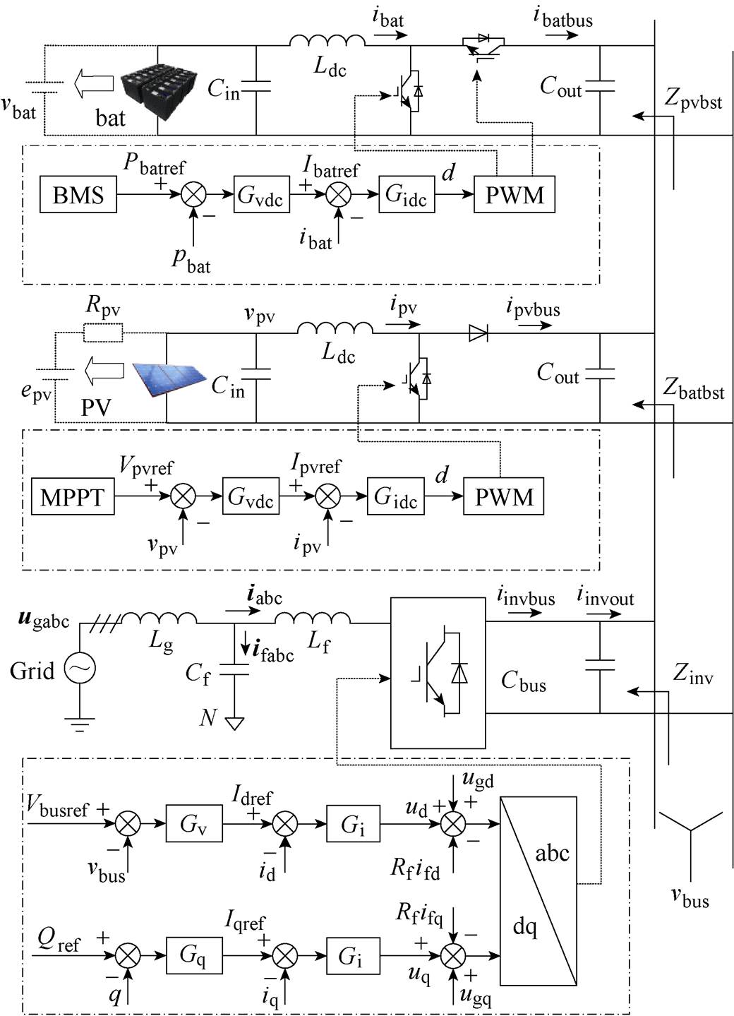
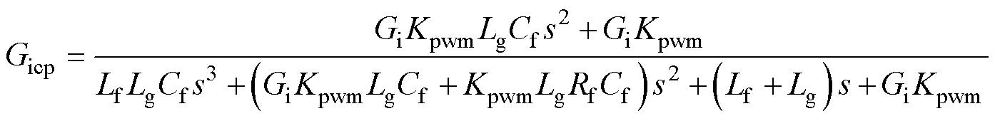
图1 共母线式光储系统拓扑结构及控制策略
Fig.1 Topology and control strategy of solar-storage inverter with common bus system
摘要 在共母线式光储逆变器中,交直流单元通过直流母线电容连接。传统的逆变器建模方法将母线电容视为无穷大,认为交直流侧运行相互解耦。然而,当直流母线电容较小时,光储逆变器的交直流侧将产生交互影响,引起电流谐振。该文以单个单元稳定运行为前提,推导出直流共母线系统稳定性的合阻抗比(CIR)判据。该判据的数学形式便于利用Bode图对并联系统的谐振源进行分析与定位。首先,对光储逆变器交直流各单元进行阻抗建模,利用合阻抗比判据分析直流侧储能单元相对于光伏单元更易与网侧发生谐振。然后,通过在电流环路加入陷波器改善储能单元的阻抗特性。最后,仿真及实验结果证实了所提合阻抗比稳定性判据的正确性。
关键词:光储系统 交直流耦合 合阻抗比 稳定性
2020年9月,中国在第75届联合国大会上正式提出“2030年实现碳达峰、2060年实现碳中和”的目标,对国内能源转型提出了迫切需求[1-2]。近两年,随着欧洲能源危机的到来以及电池技术的不断发展,光储逆变器市场行业竞争愈发激烈[3]。当前,光储逆变器普遍采用共母线拓扑[4-5],为了优化成本,逆变器企业降低直流母线电容,加剧了逆变器交直流之间的耦合程度,威胁逆变器的整体稳定性。
近年来,国内外学者已对逆变器的交直流耦合影响展开研究。在稳定性分析方面主要有特征值分析法及阻抗分析法。例如,文献[6]通过对直流微电网内各单元进行状态空间建模,研究不同电网架构下的直流交互稳定性,但状态空间维数随设备数量指数增长,出现维数灾难。文献[7-8]采用阻抗法分析直流共母线系统的稳定性,可以从根本上简化分析过程,但忽略了源间的阻抗特性差异带来的影响。文献[9]重点分析源特性差异对稳定性的影响,但是仅考虑了两单元并联,不具有普遍性。文献[10]所提阻抗比稳定判据在分析源间交互影响方面得到广泛应用[11-13]。文献[14-15]利用电压源型变流器(Voltage Source Converter, VSC)单元与负载的阻抗比来评估交直流混合系统中网侧特性对直流侧系统稳定性的影响,但仅考虑了单一形式负载特性。光储逆变器各单元的阻抗特性均不同,无法采用阻抗比方式进行判稳。文献[16]也指出了阻抗比判据在研究多源交互过程中的局限性。文献[17-18]所提广义阻抗比判据主要研究的是“同构”设备接入电网不同节点电网的强度问题,而非本文所述不同设备接入同一公共点的稳定性问题。文献[19-21]首先给出了直流系统不同类型源并联的阻抗稳定性判据,均是将系统源与负载进行分类聚合,需求出整体等效阻抗,然后利用单机阻抗比方法进行判稳。但是系统整体稳定性判据与单机阻抗的关系无法直观描述,难以定位系统中的谐振源。文献[22]提出了一种并联系统失稳责任评估和划分方法,但是该方式需要计算出谐振点和阻尼因子,难以进行可视化分析。
在阻抗特性优化方面,文献[23]通过调整控制带宽的方式使阻抗在谐振频率处呈正阻尼特性来提高系统的稳定性,但是会影响电流环的动态性能。陷波器因其具有频率选择及负谐振峰特性,不需要增加额外的采样电路,因此在具有特定谐振点的系统中得到广泛应用[24-25]。
本文首先对光储逆变器的共母线单元分别建立其阻抗模型,基于单元稳定性为前提推导出单元并联网络稳定性的合阻抗比(Combined Impedance Ratio, CIR)判据。利用该判据分析直流侧储能单元相对于光伏单元更易与网侧发生谐振。然后通过在电流环加入陷波器改善储能单元的阻抗特性。最后通过仿真及实验结果表明,所提合阻抗比稳定性判据判定结果的正确性。
共直流母线式光储逆变器由储能单元、光伏最大功率点追踪(Maximum Power Point Tracking, MPPT)单元以及逆变单元构成,它们通过变换器与公共直流母线相连接。一种典型的工作状态是网侧负责稳定直流母线电压,光伏单元执行MPPT,储能电池根据上层电池管理系统(Battery Management System, BMS)的指令进行充放电[26]。该模式下各单元的控制策略如图1所示。
图1 共母线式光储系统拓扑结构及控制策略
Fig.1 Topology and control strategy of solar-storage inverter with common bus system
图1中,光伏单元与储能单元电路模型基本相同,差异在于储能单元输入端等效为恒压源,端口电压为vbat,阻抗为0,光伏单元输入端含有等效电阻Rpv;epv为光伏板内电动势,vpv为光伏板端口电压。ibat与ipv为电感电流,ibatbus与ipvbus为储能单元和光伏单元流入母线周期平均电流;Cin与Cout分别为输入、输出滤波电容;Ldc为升压电感。
逆变单元Lf与Cf分别为滤波电感、电容,Lg为变压器及线路阻抗,Cbus为母线电容。ugabc为电网电压,iabc与ifabc分别为电感电流及电容电流周期平均值。iinvbus为逆变单元流入母线电容Cbus电流,iinvout为最终输出到直流母线的电流。逆变侧控制考虑经典的“PI+电网电压前馈[27]+有源阻尼”的基本控制方式,Gi、Gv、Gq分别为电流、电压、无功环路控制传递函数,Rfifd与Rfifq为有源阻尼控制项。在不考虑弱电网[28]影响的情况下,逆变单元的dq轴控制可以相互解耦,此时流入母线电流仅由d轴电流控制。
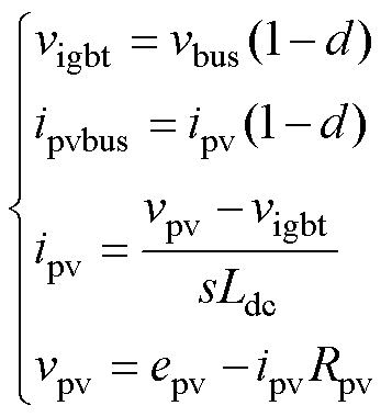
共母线式光储逆变器各单元通过母线相互连接,所述阻抗是指从母线角度,各单元流入母线电流与母线电压之间的关系。由于光伏单元与储能单元仅输入阻抗不同,本文将储能单元与光伏单元进行统一建模,以光伏单元为例,考察电流连续状态,则Boost电路稳态工作点满足
 (1)
(1)
式中,vigbt为绝缘栅双极型晶体管(Insulated Gate Bipolar Transistor, IGBT)两端电压周期平均值;d为IGBT占空比,对式(1)叠加小信号得到
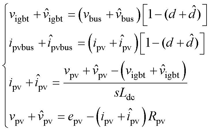 (2)
(2)
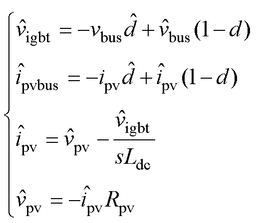
式中,上标“ ”表示小信号变量。联立方程组式(1)、式(2)并略去高阶小量可得Boost小信号模型为
 (3)
(3)
考虑光伏单元电流环控制方程为
 (4)
(4)
并小信号化得到控制环节小信号方程为
 (5)
(5)
式中,Gidc(s)为电流环控制器传递函数;Gdelay(s)为数字控制延时。上述方程组式(1)为参数方程,联立方程组式(3)、式(5)可求得 关于
关于 的关系为
的关系为
 (6)
(6)
式(6)即为光伏单元从母线角度观测的输入阻抗Zpvbst。储能单元与光伏单元的建模方法相同,忽略电池内阻,将Rpv取0即可表示储能单元的等效输入阻抗,即
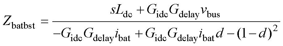 (7)
(7)
根据图1的控制策略得到逆变单元母线电压环等效控制框图2所示。
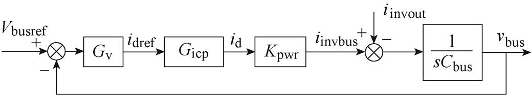
图2 网侧母线电压环等效控制框图
Fig.2 Equivalent control block diagram of the bus voltage loop on the grid side
图2中,Gv为电压环控制器传递函数,Gicp为电流环闭环传递函数,Kpwr为功率转换系数,表示流入母线电流与d轴电流之间的比值。在非弱电网情况下,根据瞬时功率理论可以得到Kpwr的值为
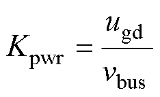 (8)
(8)
逆变侧对母线等效输出阻抗为vbus关于输出电流iinvout的传递函数,根据图2所示控制框图得到逆变侧等效阻抗为
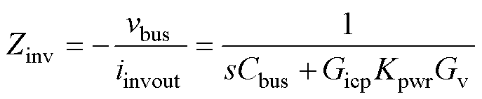 (9)
(9)
逆变单元基于旋转坐标系的电流环等效控制框图如图3所示,由静止坐标系转换到旋转坐标系时,LCL环节电压电流微分关系均会使dq轴产生耦合。图3所示的电流环精确闭环传递函数,文献[13]已有详细推导,本文不再赘述。考虑到通常Lf与Cf值较小,且电网非弱电网情况,产生的耦合效果可以忽略不计,得到d轴电流简化控制框图如图4所示。式(10)给出了电流环闭环传递函数表达式。Kpwm为逆变输出电压与调制波信号的比值。将式(10)代入式(9)即可得到逆变侧对母线电容完整的等效输入阻抗。
 (10)
(10)
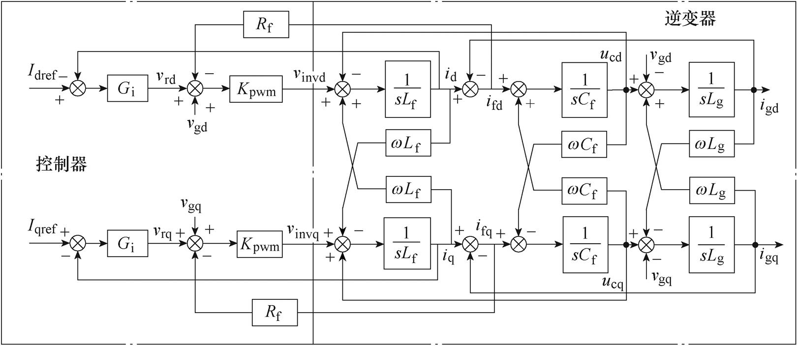
图3 网侧电流环等效控制框图
Fig.3 Current loop equivalent control block diagram on the grid side
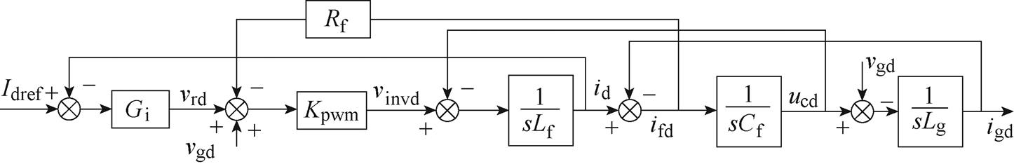
图4 网侧d轴电流环简化控制框图
Fig.4 Simplified control block diagram of the grid-side d-axis current loop
本节以单元稳定运行为前提,推导逆变器整体稳定性与单元阻抗之间的定量关系,方便对系统谐振源进行定位。
多单元并联阻抗模型如图5所示,其中单元1~n-1为电流节点,单元n为电压节点,Zn(s)为各单元输出阻抗。Gi(s)(i=1~n)为各受控源单元输出关于参考值的传递函数。通常假设每个单元独立工作时是稳定的,即Gi(s)、Zi(s)本身无右半平面极点。
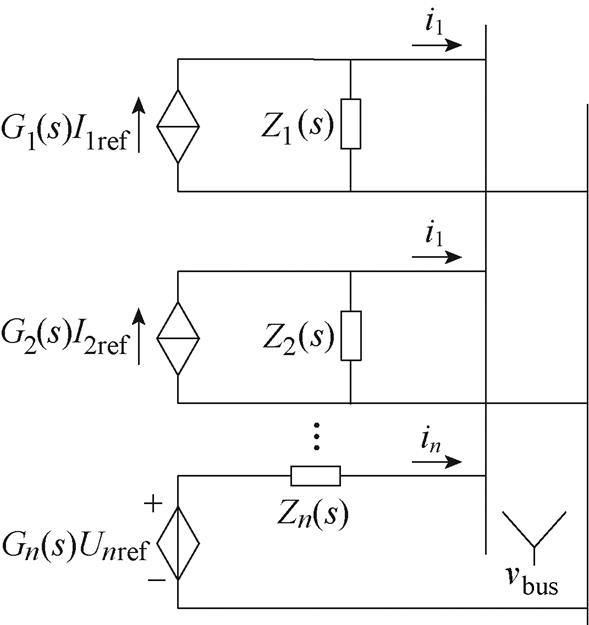
图5 多单元并联阻抗模型
Fig.5 Impedance model of a multi-module parallel system
根据叠加定理,公共母线电压vbus(s)的频域表达式为
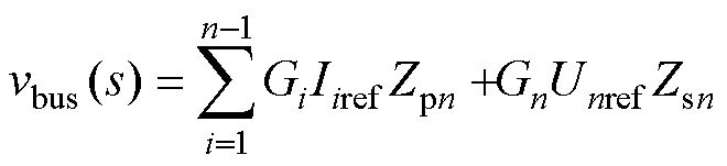 (11)
(11)
其中
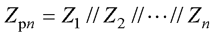 (12)
(12)
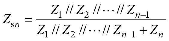 (13)
(13)
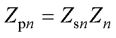
式中,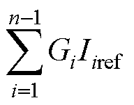 与
与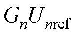 为系统总激励,由单个单元运行稳定假设条件知,激励部分无右半平面极点,因此系统稳定性取决于阻抗表达式Zpn与Zsn是否有右半平面极点。
由式(12)、式(13)不难得到
 (14)
(14)
由假设条件知, 本身不具有右半平面极点。因此Zpn与Zsn具有相同的稳定性判据。故得结论:在单元稳定运行的前提下,多单元并联稳定性的充要条件为所有单元并联阻抗不具有右半平面极点。
上述结论得到了系统整体稳定性判据,但是却无法得到单元阻抗对系统整体稳定性的影响程度,且无法利用传统的Bode图及Nyquist图进行直观的稳定性分析,因此还需要对上述稳定性判据进一步推导。
对式(13)变形可得
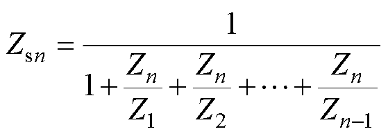 (15)
(15)
式(15)等价于单位负反馈系统的闭环传递函数,其等效开环传递函数为
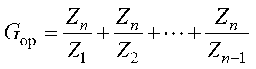 (16)
(16)
利用式(16)则可以使用传统的开环传递函数判稳方法对系统进行判稳。式(16)中,所选取稳定节点n与任一单元k的阻抗比为Zn/Zk(k n),下文均简称为单元k的阻抗比。并由此引出定义:
合阻抗比为多单元并联系统中,选取某个稳定节点阻抗作为分子,则该节点阻抗与其他各节点阻抗比值的和,称为“合阻抗比”。
合阻抗比揭示了系统中各节点阻抗比对系统整体稳定性的影响程度。其表达式利用Bode图进行分析。当系统某个单元存在谐振点时,其阻抗比在谐振点附近将远大于其他单元,对合阻抗比影响最为显著,由此定位该单元即为系统的谐振源。
本节将根据第3节的阻抗稳定性判据来分析光储系统的谐振源,并进行控制环路校正。
根据第2节推导出的输入阻抗表达式(6)、式(7)及式(9),绘制出光储逆变器各单元阻抗Bode图如图6所示。
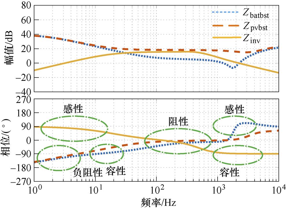
图6 光储逆变器各单元输入阻抗Bode图
Fig.6 Input impedance Bode diagram of each unit in solar-storage inverter
图6中,Zinv、Zbatbst与Zpvbst分别为网侧等效阻抗、储能单元等效阻抗以及光伏单元等效阻抗。由图6可知,网侧等效阻抗在低频段具有较低的感性阻抗,符合恒压源特性。在高频段呈容性阻抗,是由于随着频率增大,超出母线电压环控制带宽范围,母线电容本身容性特性逐渐显现。直流侧单元在低频段等效恒功率源,因此呈负阻性。中频段接近阻性,但是光伏单元阻抗曲线远大于储能单元阻抗曲线,是因为光伏输入电池板具有等效内阻,为系统提供了较大阻尼;在高频段又呈感性,导致与逆变单元容性阻抗存在谐振的可能。
为了更直观地判断系统中的谐振源,选取网侧输入阻抗Zinv作为式(16)中的Zn,绘制出储能单元及光伏单元的阻抗比Bode图如图7所示。
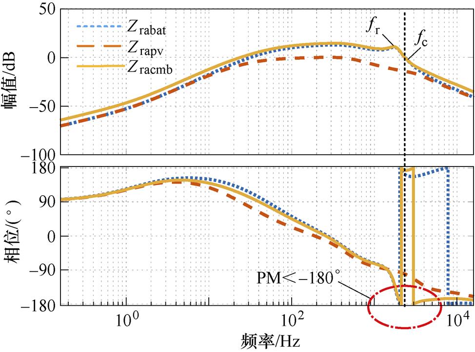
图7 光储逆变器各单元阻抗比
Fig.7 The impedance radio Bode diagram of each unit in solar-storage inverter
图7中,Zrabat、Zrapv、Zracmb分别为储能单元阻抗比、光伏单元阻抗比以及系统的合阻抗比。PM表示相位裕度。fr为系统谐振峰,fc为系统幅值穿越频率,约为2.2 kHz。在幅值穿越频率处,合阻抗比的相频曲线穿越-180°,导致系统不稳定。在谐振点附近,系统合阻抗比增益主要由储能单元提供,而光伏单元阻抗比在0 dB以下,这表明系统不稳定是由储能单元引起的。
图7中系统不稳定的直接原因是在谐振峰处系统相位裕度急剧下降,造成这种现象的原因是系统存在控制延时。图8给出了不同控制延时下的储能单元阻抗比Bode图。Td为延时时间,Ts为控制周期。可以看出,随着控制延时增大,阻抗比谐振峰增大,相位裕度急剧降低。控制延时通常是无法避免的,采用过采样方式可使控制延时降低至0.5Ts,但是这对芯片性能有较高的要求。
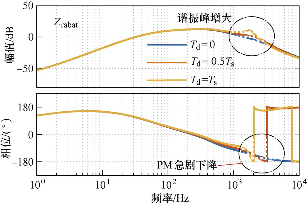
图8 不同控制延时下储能单元的阻抗比
Fig.8 Impedance ratio of energy storage unit under different control delays
光伏单元相对于储能单元,存在等效输入内阻,图9给出了不同等效内阻下光伏单元阻抗比。等效内阻为系统提供了一定阻尼,因此在中频段增益降低明显,稳定性相对增强。
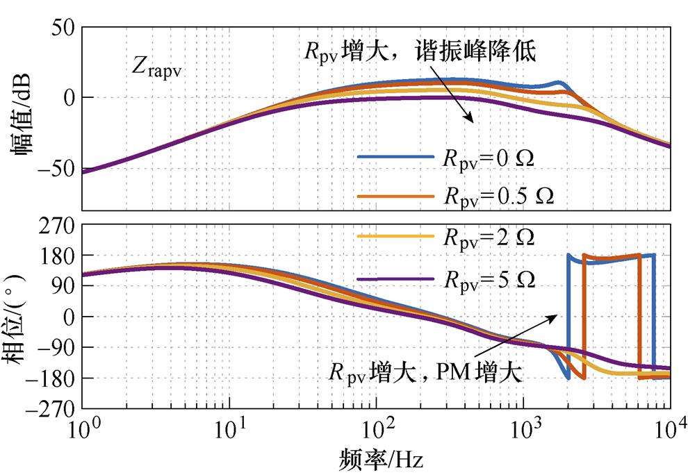
图9 不同等效内阻下光伏单元阻抗比
Fig.9 Impedance ratio of photovoltaic unit under different equivalent internal resistance
由于阻抗特性反映的是系统闭环特征,难以直观地进行控制器校正,需从系统的开环传递函数角度进行分析。光伏单元不运行时,储能单元电感电流 关于
关于 的小信号开环传递函数
 由式(17)给出,绘制其Bode图如图10曲线①所示。
 (17)
(17)
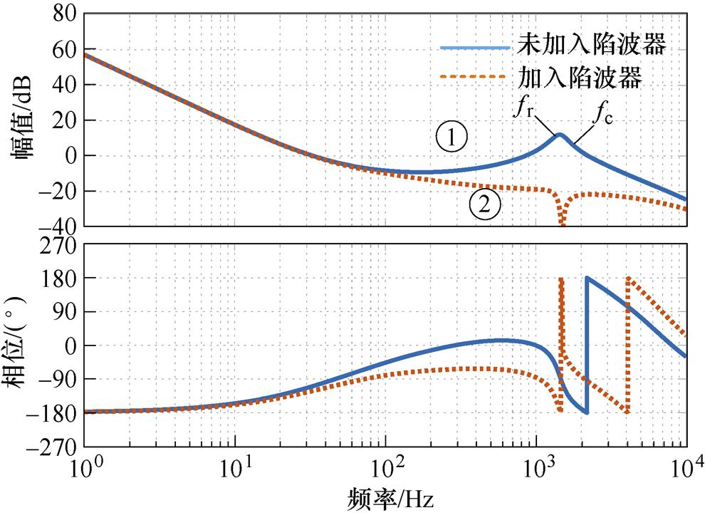
图10 加入陷波器前后电流环开环Bode图对比
Fig.10 Bode diagram comparison of current open loop before and after adding notch filter
由曲线1可知,储能单元电流环开环传递函数在高频段fr处存在谐振峰,重新穿越0 dB,导致系统不稳定。为此,本文在储能单元电流环中加入陷波器,抑制高频段的谐振峰,以提高系统稳定性。陷波器传递函数为
 (18)
(18)
式中,wT为陷波频率; 为阻尼比。加入陷波器后储能单元电流环开环传递函数Bode图如图10中曲线②所示。
通过对比曲线①、②可知,在储能单元加入陷波器后,在谐振点附近储能单元电流环增益得到抑制,幅频曲线在0 dB以下,系统稳定。此时还需重新校验系统整体稳定性,系统阻抗比如图11所示。
从图11中可以得出,储能单元加入陷波器后,系统合阻抗比幅值穿越频率处相位裕度约为20°,整体稳定性得到增强。值得注意的是,加入陷波器后,阻抗比表达式相较于未加入陷波器增加了2个右半平面极点,因此图11中fb和fc之间虽然存在一次相位穿越,但系统仍是稳定的。
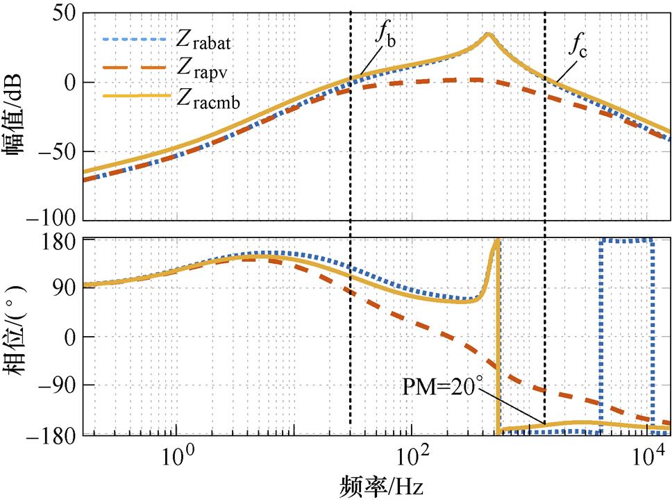
图11 加入陷波器后各单元阻抗比
Fig.11 The impedance ratio of each unit after adding notch filter
本节通过仿真和实验,对比不同情况下的电流阶跃响应波形,结果均与理论分析一致。仿真及实验所用参数见表1,逆变器额定功率为25 kW,额定线电压为400 V。
表1 控制及硬件参数
Tab.1 Control and hardware parameter table
单元参数数值 储能单元Cin, Cout/mF5 Ldc/mH68 电流环Kp1.4×10-3 Ki0.75 陷波器x4 陷波器wT3 000p 控制频率/kHz12 开关频率/kHz48 光伏单元光伏板内阻Rpv/W5 逆变单元Cbus/mF150 Cf/mF17 Lg/mH50 Lf/mH400 电流环Kp1.88 Ki88 有源阻尼系数Rf1 电压环Kp0.3 Ki11.4
图12为储能单元运行时,未加入陷波器,控制延时Td=Ts,各环节仿真波形。iA,B,C表示逆变侧输出A、B、C三相电流。输入电压为620 V,母线电压设定为650 V,直流侧工作在电流环模式,仿真时间t =0.9 s时电流环指令由半载阶跃至满载,此时直流侧电流振荡剧烈,并通过母线耦合至网侧,振荡频率约为2.1 kHz,与图7分析基本一致。
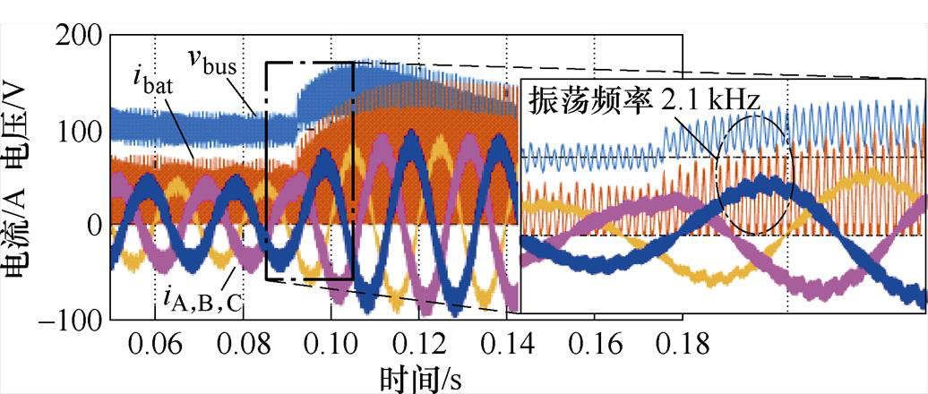
图12 控制延时Td=Ts储能单元电流仿真波形
Fig.12 The current simulation waveforms of energy storage unit when the control delay Td=Ts
图13与图12测试工况一致,控制延时Td= 0.5Ts。可见系统控制延时减小后,电流阶跃响应可以在2~3个振荡周期内快速收敛,系统稳定性显著提高。与图8分析结果基本一致。为了便于观察,图中输入电感电流加100 A偏置,母线电压-550 V偏置。
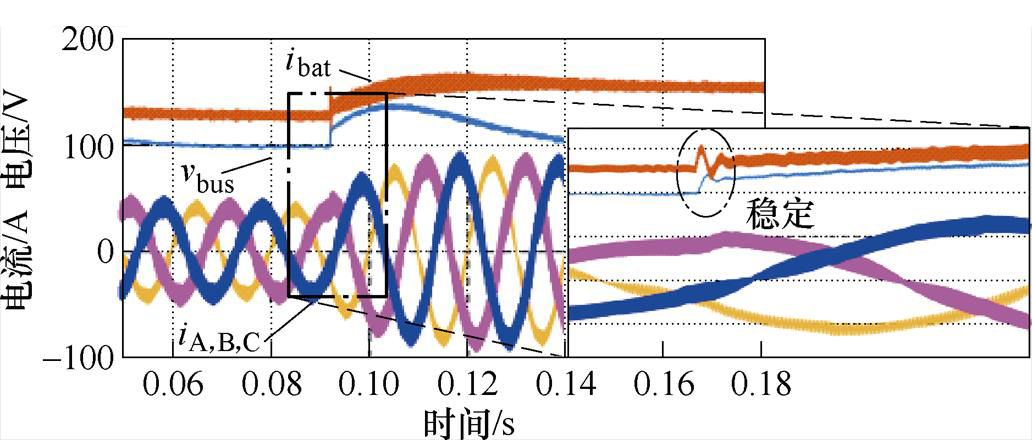
图13 控制延时Td=0.5Ts储能单元电流仿真波形
Fig.13 The current simulation waveforms of energy storage unit when the control delay Td=0.5Ts
图14、图15分别为光伏单元运行时,未加入陷波器,控制延时Td=Ts,光伏板等效输入电阻Rpv=0.5 W及Rpv=2 W,各环节仿真波形。仿真时间t=0.9 s时电流环指令由半载阶跃至满载。对比图12及图13、图14可以发现,在相同的控制延时下,光伏单元等效输入电阻对电流振荡起到明显抑制效果,这与图9分析结果相吻合。
图16为储能单元运行时,加入陷波器前后的电流仿真波形,仿真时间0.08 s加入陷波器,在加入陷波器之前,电流振荡频率约为2.13 kHz。加入陷波器之后,输入电感电流稳定,验证了图10、图11的分析结果及所提策略的有效性。
图17所示为加入陷波器后电感电流阶跃响应波形。仿真时间0.11 s电流指令由半载阶跃至满载。其响应分为两个阶段,低频段响应时间约为60 ms,与图11中第1次幅值穿越频率fb相对应。高频段振荡频率约为1.72 kHz,与图11中第2次幅值穿越频率fc相对应,表明系统建模及理论推导是正确的。
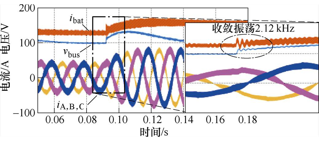
图14 Rpv=0.5 W 光伏单元电流仿真波形
Fig.14 The current simulation waveforms of photovoltaic unit when Rpv=0.5 W
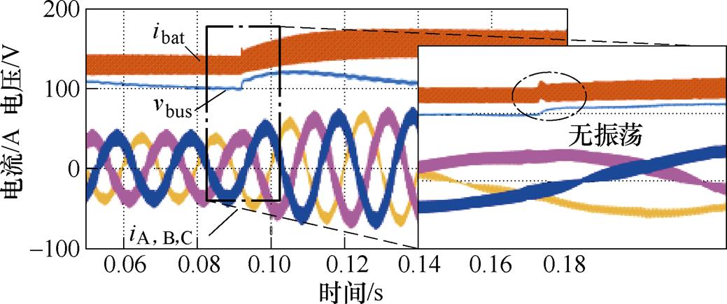
图15 Rpv=2 W 光伏单元电流仿真波形
Fig.15 The current simulation waveforms of photovoltaic unit when Rpv=2 W
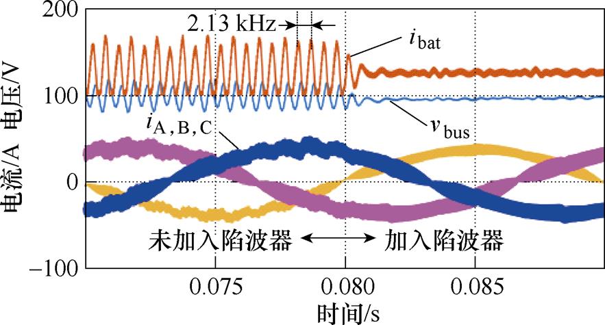
图16 加入陷波器前后储能单元电流仿真波形
Fig.16 The current simulation waveforms of energy storage unit before and after adding notch filter
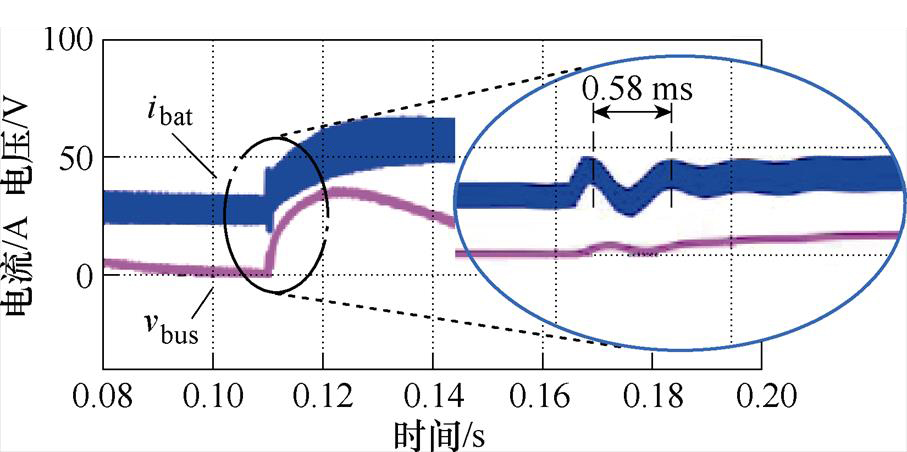
图17 加入陷波器后储能单元电感电流阶跃波形
Fig.17 Inductance current step waveforms of energy storage unit after adding notch filter
图18、图19分别为加入陷波器前、后储能单元输入电感电流及母线电压实验波形对比。输入电压为620 V,母线电压设定为650 V,工作在电流环模式。在加入陷波器之前,储能单元与网侧母线发生谐振,振荡频率为2.15 kHz,加入陷波器后系统稳定,与图16仿真现象基本一致。
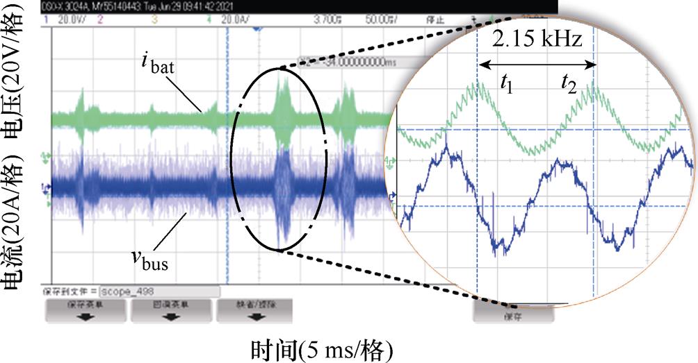
图18 加入陷波器前储能单元电流实验波形
Fig.18 The current experimental waveforms of energy storage unit without adding notch filter
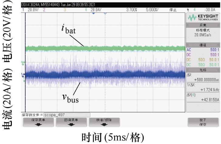
图19 加入陷波器后储能单元电流实验波形
Fig.19 The current experimental waveforms of energy storage unit with adding notch filter
图20为储能单元电感电流阶跃及母线电压波形,输入电压为620 V,母线电压设定为650 V,t1时刻电流指令由半载阶跃至满载。其低频响应时间及高频响应时间均与图17中的仿真波形吻合,这表明仿真模型及仿真结果是正确的。而且,为测量及观察方便,母线电压示波器通道倒置。
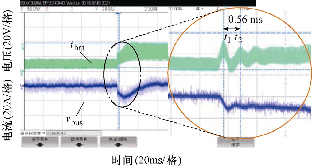
图20 加入陷波器后储能单元电流阶跃波形
Fig.20 The current step waveforms of energy storage unit with adding notch filter
以上仿真及实验结果表明,直流侧单元控制延时是导致高频段阻抗特性发生突变继而导致谐振的本质原因,而光伏单元相对于储能单元具备天然的输入等效内阻,可以极大程度地抑制阻抗特性的变化。所提陷波器校正策略对电流谐振起到了良好的抑制效果。
本文对光储逆变器直流侧单元与网侧单元交互影响进行了建模分析,通过阻抗法推导出多单元并联模型的合阻抗比稳定判据。该判据与传统开环传递函数判稳方法一致,借助Bode图易于定位系统中的谐振源。通过该方法首先定位光储逆变器中电流谐振原因是储能单元阻抗比在高频段存在谐振峰,最后通过在电流环加入陷波器解决了该问题。仿真和实验验证了所提判据的正确性及陷波器校正方法的有效性。
参考文献
[1] 黄雨涵, 丁涛, 李雨婷, 等. 碳中和背景下能源低碳化技术综述及对新型电力系统发展的启示[J]. 中国电机工程学报, 2021, 41(增刊1): 28-51.
Huang Yuhan, Ding Tao, Li Yuting, et al. Decar- bonization technologies and inspirations for the development of novel power systems in the context of carbon neutrality[J]. Proceedings of the CSEE, 2021, 41(S1): 28-51.
[2] 叶晨, 王蓓蓓, 薛必克, 等. 考虑超售的共享分布式光储混合运营模式协同策略研究[J]. 电工技术学报, 2022, 37(7): 1836-1846.
Ye Chen, Wang Beibei, Xue Bike, et al. Study on the coordination strategy of sharing distributed photo- voltaic energy storage hybrid operation mode con- sidering overselling[J]. Transactions of China Elec- trotechnical Society, 2022, 37(7): 1836-1846.
[3] 刘建国. 乌克兰危机背景下全球能源发展新特征分析[J]. 国际石油经济, 2022, 30(11): 57-63.
Liu Jianguo. New characteristics of global energy development under the Ukraine issue[J]. International petroleum economy, 2022, 30(11): 57-63.
[4] 张权宝, 唐芬, 陶庭欢, 等. 光储一体化变流器并联系统的功率协调控制[J]. 电力电子技术, 2022, 56(9): 70-73.
Zhang Quanbao, Tang Fen, Tao Tinghuan, et al. Power coordinated control of PV-storage integrated converter parallel system[J]. Power Electronics, 2022, 56(9): 70-73.
[5] Xu Zhongyan, Tao Shengyu, Fan Hongtao, et al. Power limit control strategy for household photo- voltaic and energy storage inverter[J]. Electronics, 2021, 10(14): 1704.
[6] 朱晓荣, 李铮, 孟凡奇. 基于不同网架结构的直流微电网稳定性分析[J]. 电工技术学报, 2021, 36(1): 166-178.
Zhu Xiaorong, Li Zheng, Meng Fanqi. Stability analysis of DC microgrid based on different grid structures[J]. Transactions of China Electrotechnical Society, 2021, 36(1): 166-178.
[7] 彭方成, 范学鑫, 王瑞田, 等. 大容量DC-DC 变流器输出阻抗特性分析及应用[J]. 电工技术学报, 2021, 36(16): 3422-3432.
Peng Fangcheng, Fan Xuexin, Wang Ruitian, et al. Analysis and application of output impedance characteristics of high-capacity DC-DC converter[J]. Transactions of China Electrotechnical Society, 2021, 36(16): 3422-3432.
[8] 姚雨迎, 张东来, 徐殿国. 级联式DC/DC变换器输出阻抗的优化设计与稳定性[J]. 电工技术学报, 2009, 24(3): 147-152.
Yao Yuying, Zhang Donglai, Xu Dianguo. Output impedance optimization and stability for cascade DC/DC converter[J]. Transactions of China Electro- technical Society, 2009, 24(3): 147-152.
[9] 王晴, 刘增, 韩鹏程, 等. 基于变流器输出阻抗的直流微电网下垂并联系统振荡机理与稳定边界分析[J]. 电工技术学报, 2023, 38(8): 2148-2161.
Wang Qing, Liu Zeng, Han Pengcheng, et al. Analysis of oscillation mechanism and stability boundary of droop-controlled parallel converters based on output impedances of individual converters in DC micro- grids[J]. Transactions of China Electrotechnical Society, 2023, 38(8): 2148-2161.
[10] Sun Jian. Impedance-based stability criterion for grid- connected inverters[J]. IEEE Transactions on Power Electronics, 2011, 26(11): 3075-3078.
[11] 汪春江, 孙建军, 宫金武, 等. 并网逆变器与电网阻抗交互失稳机理及阻尼策略[J]. 电工技术学报, 2020, 35(增刊2): 503-511.
Wang Chunjiang, Sun Jianjun, Gong Jinwu, et al. Mechanism and damping strategy of interactive instability between grid-connected inverter and grid impedance[J]. Transactions of China Electrotechnical Society, 2020, 35(S2): 503-511.
[12] 曾锋, 李崇涛, 舒进, 等. 基于阻抗法的稳定性判据论证及其适用性分析[J]. 电力系统自动化, 2021, 45(8): 146-154.
Zeng Feng, Li Chongtao, Shu Jin, et al. Demon- stration of stability criterion based on impedance method and analysis on its applicability[J]. Auto- mation of Electric Power Systems, 2021, 45(8): 146-154.
[13] 李杨, 帅智康, 方俊彬, 等. 基于阻抗测量的多逆变器系统稳定性校验方法[J]. 电力系统自动化, 2021, 45(11): 95-101.
Li Yang, Shuai Zhikang, Fang Junbin, et al. Stability check method for multi-inverter system based on impedance measurement[J]. Automation of Electric Power Systems, 2021, 45(11): 95-101.
[14] 年珩, 杨军, 陈亮, 等. 交直流混合供电系统直流侧阻抗建模及稳定性分析[J]. 高电压技术, 2020, 46(10): 3477-3490.
Nian Heng, Yang Jun, Chen Liang, et al. DC impedance modeling and stability analysis of AC/DC hybrid power supply system[J]. High Voltage Engineering, 2020, 46(10): 3477-3490.
[15] 黄旭程, 刘亚丽, 陈燕东, 等. 直流电网阻抗建模与振荡机理及稳定控制方法[J]. 电力系统保护与控制, 2020, 48(7): 108-117.
Huang Xucheng, Liu Yali, Chen Yandong, et al. Impedance-based modeling, stability analysis and virtual damping approach in DC grid[J]. Power System Protection and Control, 2020, 48(7): 108-117.
[16] 李霞林, 郭力, 黄迪, 等. 直流配电网运行控制关键技术研究综述[J]. 高电压技术, 2019, 45(10): 3039-3049.
Li Xialin, Guo Li, Huang Di, et al. Research review on operation and control of DC distribution net- works[J]. High Voltage Engineering, 2019, 45(10): 3039-3049.
[17] 辛焕海, 章枫, 于洋, 等. 多馈入直流系统广义短路比: 定义与理论分析[J]. 中国电机工程学报, 2016, 36(3): 633-647.
Xin Huanhai, Zhang Feng, Yu Yang, et al. Gen- eralized short circuit ratio for multi-infeed DC systems: definition and theoretical analysis[J]. Proceedings of the CSEE, 2016, 36(3): 633-647.
[18] 辛焕海, 甘德强, 鞠平. 多馈入电力系统广义短路比: 多样化新能源场景[J]. 中国电机工程学报, 2020, 40(17): 5516-5527.
Xin Huanhai, Gan Deqiang, Ju Ping. Generalized short circuit ratio of power systems with multiple power electronic devices: analysis for various renewable power generations[J]. Proceedings of the CSEE, 2020, 40(17): 5516-5527.
[19] 张学, 裴玮, 邓卫, 等. 含恒功率负载的交直流混联配电系统稳定性分析[J]. 中国电机工程学报, 2017, 37(19): 5572-5582, 5834.
Zhang Xue, Pei Wei, Deng Wei, et al. Stability analysis of AC/DC hybrid distribution system with constant power loads[J]. Proceedings of the CSEE, 2017, 37(19): 5572-5582, 5834.
[20] Wildrick C M, Lee F C, Cho B H, et al. A method of defining the load impedance specification for a stable distributed power system[J]. IEEE Transactions on Power Electronics, 1995, 10(3): 280-285.
[21] Feng Xiaogang, Liu Jinjun, Lee F C. Impedance specifications for stable DC distributed power systems[J]. IEEE Transactions on Power Electronics, 2002, 17(2): 157-162.
[22] 刘康礼. 弱电网条件下多逆变器并联控制关键技术研究[D]. 南京: 东南大学, 2017.
[23] 卢浩, 朱琳, 赵学深, 等. 基于负载变流器控制带宽的直流系统稳定性分析[J]. 电力系统自动化, 2023, 47(3): 153-160.
Lu Hao, Zhu Lin, Zhao Xueshen, et al. Stability analysis of dc system based on control bandwidth of load converter[J]. Automation of Electric Power Systems, 2023, 47(3): 153-160.
[24] 耿乙文, 田芳芳, 孙帅, 等. 一种基于虚拟同步发电机的电流谐波抑制方法[J]. 电工技术学报, 2018, 33(5): 1040-1050.
Geng Yiwen, Tian Fangfang, Sun Shuai, et al. A method of current harmonics suppression based on VSG[J]. Transactions of China Electrotechnical Society, 2018, 33(5): 1040-1050.
[25] 郑堃, 周林, 龙贵欣, 等. 一种针对数字控制下光伏并网逆变器的陷波器滞后补偿方法[J]. 中国电机工程学报, 2019, 39(6): 1749-1757, 1871.
Zheng Kun, Zhou Lin, Long Guixin, et al. A lag compensation method based on Notch filter for PV grid-connected inverter under digital control[J]. Pro- ceedings of the CSEE, 2019, 39(6): 1749-1757, 1871.
[26] 武龙星, 庞辉, 晋佳敏, 等. 基于电化学模型的锂离子电池荷电状态估计方法综述[J]. 电工技术学报, 2022, 37(7): 1703-1725.
Wu Longxing, Pang Hui, Jin Jiamin, et al. A review of soc estimation methods for lithium-ion batteries based on electrochemical model[J]. Transactions of China Electrotechnical Society, 2022, 37(7): 1703- 1725.
[27] 徐健, 曹鑫, 郝振洋, 等. 基于电网谐波电压前馈的虚拟同步整流器电流谐波抑制方法[J]. 电工技术学报, 2022, 37(8): 2018-2029.
Xu Jian, Cao Xin, Hao Zhenyang, et al. A harmonic- current suppression method for virtual synchronous rectifier based on feedforward of grid harmonic voltage[J]. Transactions of China Electrotechnical Society, 2022, 37(8): 2018-2029.
[28] 涂春鸣, 邹凯星, 高家元, 等. 基于不对称正负反馈效应的PQ功率控制并网逆变器稳定性分析[J]. 电工技术学报, 2023, 38(2): 496-509.
Tu Chunming, Zou Kaixing, Gao Jiayuan, et al. Stability analysis of grid-connected inverter under PQ power control based on asymmetric positive-negative- feedback effects[J]. Transactions of China Electro- technical Society, 2023, 38(2): 496-509.
Abstract In solar-storage inverters, the photovoltaic unit, the energy storage unit on the DC side, and the inverter unit on the AC side are interconnected through a DC bus. Typically, the DC bus serves to isolate the operation of each module. However, as the bus capacity reduces, the inter-module coupling effect emerges, leading to oscillations in the bus voltage and current. Assessing the stability of the multi-module interconnected coupling system, identifying the resonance source, and eliminating oscillations have become major concerns.
The DC bus stability issue in solar-storage inverters can be equated to the stability problem of a multi-module parallel model. In previous studies, the “impedance ratio” method was commonly used to assess the stability of multi-module interactive systems. However, the impedance ratio method can only assess the stability of interactions between two-port sources. When dealing with multi-module interactions, the system is usually divided into “source” and “load” components. This approach should be more conducive to identifying and attributing resonance causes within specific units. Therefore, this paper proposes a combined impedance ratio stability criterion based on the stable operation of single modules. It deduces that the number of poles in the right half-plane of the parallel impedance of each module impedance in the system determines the stability of the DC parallel system. Accordingly, the system stability criterion is transformed into the sum of the impedance ratios of each unit. This mathematical form is beneficial for assessing system stability using the traditional Bode diagram stability method. The source of system resonance is determined by comparing the contribution of the amplitude-frequency gain of each unit's impedance ratio Bode diagram to the system's combined impedance ratio at the resonance frequency.
By impedance modeling for each unit of the solar-storage inverter and analyzing the impedance ratio Bode diagram, it is concluded that the energy storage unit and its rapid change of the impedance characteristics in high frequency can cause system resonance. In contrast, the photovoltaic unit has an equivalent input internal resistance that suppresses the change in its impedance characteristics, remaining resistive and inductive at all times. Subsequently, a notch filter is incorporated into the energy storage unit's controller to reduce the resonance peak of the open-loop transfer function in high frequency and enhance the output impedance characteristics.
Finally, the developed model is validated through simulation and experimentation. The cause of system resonance can be accurately analyzed and identified through comparative analysis and applying the combined impedance ratio criterion. The control delay of the energy storage unit indeed causes the mutual resonance problem of the photovoltaic storage inverter. The photovoltaic unit has a natural equivalent internal resistance that contributes very little to the resonance peak and is not responsible for the system resonance. Simulation and experimental results demonstrate the correctness of the model and the effectiveness of the proposed strategy.
keywords:Solar-storage system, DC and grid side coupling, combined impedance ratio, stability
DOI: 10.19595/j.cnki.1000-6753.tces.230286
中图分类号:TM615
国网浙江省电力有限公司科技资助项目(5211JX1900CX)。
收稿日期 2023-05-24
改稿日期 2023-06-11
李 达 男,1995年生,硕士研究生,光伏控制软件高级工程师,研究方向为并网逆变器稳定性分析及控制。E-mail: l1d2moan@126.com(通信作者)
张 涛 男,1981年生,教授,博士生导师,研究方向为新能源发电与并网技术、电力系统优化运行、高电压绝缘及测试。E-mail: unifzhang@foxmail.com
(编辑 陈 诚)